EP2017100A1 - Vehicle roll control system - Google Patents
Vehicle roll control system Download PDFInfo
- Publication number
- EP2017100A1 EP2017100A1 EP08156550A EP08156550A EP2017100A1 EP 2017100 A1 EP2017100 A1 EP 2017100A1 EP 08156550 A EP08156550 A EP 08156550A EP 08156550 A EP08156550 A EP 08156550A EP 2017100 A1 EP2017100 A1 EP 2017100A1
- Authority
- EP
- European Patent Office
- Prior art keywords
- fluid
- pressure
- hydraulic actuators
- control system
- pressure relief
- Prior art date
- Legal status (The legal status is an assumption and is not a legal conclusion. Google has not performed a legal analysis and makes no representation as to the accuracy of the status listed.)
- Withdrawn
Links
Images


Classifications
-
- B—PERFORMING OPERATIONS; TRANSPORTING
- B60—VEHICLES IN GENERAL
- B60G—VEHICLE SUSPENSION ARRANGEMENTS
- B60G21/00—Interconnection systems for two or more resiliently-suspended wheels, e.g. for stabilising a vehicle body with respect to acceleration, deceleration or centrifugal forces
- B60G21/02—Interconnection systems for two or more resiliently-suspended wheels, e.g. for stabilising a vehicle body with respect to acceleration, deceleration or centrifugal forces permanently interconnected
- B60G21/04—Interconnection systems for two or more resiliently-suspended wheels, e.g. for stabilising a vehicle body with respect to acceleration, deceleration or centrifugal forces permanently interconnected mechanically
- B60G21/05—Interconnection systems for two or more resiliently-suspended wheels, e.g. for stabilising a vehicle body with respect to acceleration, deceleration or centrifugal forces permanently interconnected mechanically between wheels on the same axle but on different sides of the vehicle, i.e. the left and right wheel suspensions being interconnected
- B60G21/055—Stabiliser bars
- B60G21/0551—Mounting means therefor
- B60G21/0553—Mounting means therefor adjustable
- B60G21/0555—Mounting means therefor adjustable including an actuator inducing vehicle roll
-
- B—PERFORMING OPERATIONS; TRANSPORTING
- B60—VEHICLES IN GENERAL
- B60G—VEHICLE SUSPENSION ARRANGEMENTS
- B60G2202/00—Indexing codes relating to the type of spring, damper or actuator
- B60G2202/10—Type of spring
- B60G2202/13—Torsion spring
- B60G2202/135—Stabiliser bar and/or tube
-
- B—PERFORMING OPERATIONS; TRANSPORTING
- B60—VEHICLES IN GENERAL
- B60G—VEHICLE SUSPENSION ARRANGEMENTS
- B60G2202/00—Indexing codes relating to the type of spring, damper or actuator
- B60G2202/40—Type of actuator
- B60G2202/41—Fluid actuator
- B60G2202/413—Hydraulic actuator
-
- B—PERFORMING OPERATIONS; TRANSPORTING
- B60—VEHICLES IN GENERAL
- B60G—VEHICLE SUSPENSION ARRANGEMENTS
- B60G2202/00—Indexing codes relating to the type of spring, damper or actuator
- B60G2202/40—Type of actuator
- B60G2202/41—Fluid actuator
- B60G2202/414—Fluid actuator using electrohydraulic valves
-
- B—PERFORMING OPERATIONS; TRANSPORTING
- B60—VEHICLES IN GENERAL
- B60G—VEHICLE SUSPENSION ARRANGEMENTS
- B60G2204/00—Indexing codes related to suspensions per se or to auxiliary parts
- B60G2204/62—Adjustable continuously, e.g. during driving
-
- B—PERFORMING OPERATIONS; TRANSPORTING
- B60—VEHICLES IN GENERAL
- B60G—VEHICLE SUSPENSION ARRANGEMENTS
- B60G2204/00—Indexing codes related to suspensions per se or to auxiliary parts
- B60G2204/80—Interactive suspensions; arrangement affecting more than one suspension unit
- B60G2204/81—Interactive suspensions; arrangement affecting more than one suspension unit front and rear unit
-
- B—PERFORMING OPERATIONS; TRANSPORTING
- B60—VEHICLES IN GENERAL
- B60G—VEHICLE SUSPENSION ARRANGEMENTS
- B60G2206/00—Indexing codes related to the manufacturing of suspensions: constructional features, the materials used, procedures or tools
- B60G2206/01—Constructional features of suspension elements, e.g. arms, dampers, springs
- B60G2206/011—Modular constructions
- B60G2206/0116—Integrated distribution control units with valves, accumulators, PCB's or the like
-
- B—PERFORMING OPERATIONS; TRANSPORTING
- B60—VEHICLES IN GENERAL
- B60G—VEHICLE SUSPENSION ARRANGEMENTS
- B60G2400/00—Indexing codes relating to detected, measured or calculated conditions or factors
- B60G2400/50—Pressure
- B60G2400/51—Pressure in suspension unit
-
- B—PERFORMING OPERATIONS; TRANSPORTING
- B60—VEHICLES IN GENERAL
- B60G—VEHICLE SUSPENSION ARRANGEMENTS
- B60G2600/00—Indexing codes relating to particular elements, systems or processes used on suspension systems or suspension control systems
- B60G2600/22—Magnetic elements
- B60G2600/26—Electromagnets; Solenoids
-
- B—PERFORMING OPERATIONS; TRANSPORTING
- B60—VEHICLES IN GENERAL
- B60G—VEHICLE SUSPENSION ARRANGEMENTS
- B60G2800/00—Indexing codes relating to the type of movement or to the condition of the vehicle and to the end result to be achieved by the control action
- B60G2800/01—Attitude or posture control
- B60G2800/012—Rolling condition
-
- B—PERFORMING OPERATIONS; TRANSPORTING
- B60—VEHICLES IN GENERAL
- B60G—VEHICLE SUSPENSION ARRANGEMENTS
- B60G2800/00—Indexing codes relating to the type of movement or to the condition of the vehicle and to the end result to be achieved by the control action
- B60G2800/90—System Controller type
- B60G2800/91—Suspension Control
- B60G2800/912—Attitude Control; levelling control
- B60G2800/9122—ARS - Anti-Roll System Control
Definitions
- Each second actuator 14, 14' comprises the housing 30, 30'; a piston 48, 48' sealably slidably mounted inside the housing; a compression chamber 50, 50' and a rebound chamber 52, 52' defined by the piston inside the housing; the piston rod 26, 26' connected to the piston, extending through the rebound chamber, and out of the housing; a fluid line 54, 54' connected to the compression chamber; and a fluid line 56, 56' connected to the rebound chamber.
- the compression chambers 40, 40' of the first actuators 12, 12' and the rebound chambers 52, 52' of the second actuators 14, 14' are fluidly connected to the pump 66 in order to receive pressurised fluid. If the second pressure relief valve 74 remains at its first or rest position when the first pressure relief valve 72 and the directional valve 76 are actuated to their second position, the compression chambers 40, 40' of the first actuators 12, 12' and the rebound chambers 52, 52' of the second actuators 14, 14' are fluidly connected to the tank 68.
- the second actuator 14, 14' has been omitted and is replaced by a substantially rigid arm (not shown) such that a single hydraulic actuator is associated with each of the front and rear axles 34, 36.
- the rebound chambers 42, 42' of the first actuators 12, 12' are fluidly connected to the pump 66 in order to receive pressurised fluid.
- the compression chambers 44, 44' of the first actuators 12, 12' are fluidly connected to the pump 66 in order to receive pressurised fluid.
- Other aspects of the second embodiment, and the operation of the roll control system are substantially identical to that above with respect to the first embodiment.
- each hydraulic actuator may be reversed with the housing connected to one end of the torsion bar, and the piston rod attachable to the axle.
- drop-link hydraulic actuators are shown, it will be appreciated that other designs of hydraulic actuator may be used.
Landscapes
- Engineering & Computer Science (AREA)
- Mechanical Engineering (AREA)
- Vehicle Body Suspensions (AREA)
Abstract
Description
-
EP-A-0783986 describes a roll control system in which hydraulic actuators are powered to provide active roll control for the vehicle. The actuators generate torsion in the vehicle's torsion bars.WO-A-02/83439 EP-A-1103395 discloses a vehicle roll control system in which a pair of directional valves and a pressure control valve are used to control the movement of the piston of hydraulic actuators associated with the front and rear axles of a motor vehicle.WO-A-03/093041 WO-A-2005/108128 discloses a roll control system in which the control means for the hydraulic circuit is capable of providing fluid pressure to the first fluid chamber of the front hydraulic actuator which is different from the fluid pressure provided to the first fluid chamber of the rear hydraulic actuator; and/or is capable of providing fluid pressure to the second fluid chamber of the front hydraulic actuator which is different from the fluid pressure provided to second fluid chamber of the rear hydraulic actuator. - The aim of the present invention is to provide a roll control system which is an improvement to known arrangements.
- A roll control system in accordance with the present invention is defined by the features specified in
Claim 1. - The present invention provides a system which allows an aggressive roll control strategy and balance strategy which leads to improvements in motion, turning, and stability (braking in turn at high speed). The present invention also provides continuous control between right turn and left turn, and is a single channel system which allows adaptive front/rear handling balance with load, speed and other factors, improving vehicle stability and control.
- The present invention will now be described, by way of example, with reference to the accompanying drawings, in which:-
-
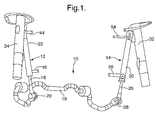
Figure 1 is a view of the hydraulic actuators and torsion bar of a roll control system in accordance with the present invention for one axle of a motor vehicle; -
Figure 2 is a schematic view of a roll control system in accordance with the present invention, with the hydraulic system and electrical control system omitted for clarity; -
Figure 3 is a schematic view of a roll control system in accordance with the present invention showing a first embodiment of the hydraulic system; and -
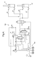
Figure 4 is a schematic view of a roll control system in accordance with the present invention showing a second embodiment of the hydraulic system. -
Figure 1 shows a portion of aroll control system 10 in accordance with the present invention for one axle of a motor vehicle. Theroll control system 10 includes a firsthydraulic actuator 12, a secondhydraulic actuator 14, and atorsion bar 16. Thefirst actuator 12 has apiston rod 18 which is fixed to oneend 20 of thetorsion bar 16; and ahousing 22 which is connected to one of the shock absorbers 24 associated with the vehicle axle. Thesecond actuator 14 has apiston rod 26 which is fixed to theother end 28 of thetorsion bar 16; and ahousing 30 which is connected to the other shock absorber 32 associated with the vehicle axle. The first andsecond actuators - In
Figure 2 , further details of theroll control system 10 ofFigure 1 are shown in connection with thefront axle 34 and therear axle 36 of the vehicle. The first andsecond actuators torsion bar 16 for thefront axle 34 are substantially identical, and substantially identical to the first and second actuators 12', 14' for therear axle 36. Eachfirst actuator 12, 12' comprises thehousing 22, 22'; apiston 38, 38' sealably slidably mounted inside the housing; acompression chamber 40, 40' and arebound chamber 42, 42' defined by the piston inside the housing; thepiston rod 18, 18' connected to the piston, extending through the rebound chamber, and out of the housing; afluid line 44, 44' connected to the compression chamber; and afluid line 46, 46' connected to the rebound chamber. Eachsecond actuator 14, 14' comprises thehousing 30, 30'; apiston 48, 48' sealably slidably mounted inside the housing; acompression chamber 50, 50' and arebound chamber 52, 52' defined by the piston inside the housing; thepiston rod 26, 26' connected to the piston, extending through the rebound chamber, and out of the housing; afluid line 54, 54' connected to the compression chamber; and afluid line 56, 56' connected to the rebound chamber. -
Figure 3 shows a first embodiment of thehydraulic system 62 andelectrical control system 64 for theroll control system 10 ofFigures 1 and2 . The hydraulic system includes afluid pump 66, a tank orreservoir 68, apressure control valve 70, a firstpressure relief valve 72, a secondpressure relief valve 74, and adirectional valve 76. Theelectrical control system 64 includes acontrol module 78 which is electrically connected to thepump 66, thepressure control valve 70, thepressure relief valves directional valve 76, to control the operation thereof. Themodule 78 is also connected topressure sensors pressure relief valve pressure sensor 85 which monitors the applied fluid pressure from thefluid pump 66 as control by thepressure control valve 70. Themodule 78 is also connected to other vehicle sensors such as a lateral g sensor 86 (which monitors the sideways acceleration of the vehicle), a steering sensor 88 (which monitors the steering angle of the front wheels), avehicle speed sensor 90, and/or any other relevant parameter. From the signals from the various sensors, thecontrol module 78 determines if roll control is required and actuates thepressure control valve 70, thepressure relief valves - In this first embodiment, each
pressure relief valve directional valve 76 are solenoid actuated and each has two positions. When thepressure relief valves directional valve 76 are in their first or rest position, as shown inFigure 3 , thecompression chamber actuator rebound chamber pressure relief valve 72 and thedirectional valve 76 are actuated to their second position, therebound chambers 42, 42' of thefirst actuators 12, 12' and thecompression chambers 50, 50' of thesecond actuators 14, 14' are fluidly connected to thepump 66 in order to receive pressurised fluid. When the secondpressure relief valve 74 and thedirectional valve 76 are actuated to their second position, thecompression chambers 40, 40' of thefirst actuators 12, 12' and therebound chambers 52, 52' of thesecond actuators 14, 14' are fluidly connected to thepump 66 in order to receive pressurised fluid. If the secondpressure relief valve 74 remains at its first or rest position when the firstpressure relief valve 72 and thedirectional valve 76 are actuated to their second position, thecompression chambers 40, 40' of thefirst actuators 12, 12' and therebound chambers 52, 52' of thesecond actuators 14, 14' are fluidly connected to thetank 68. If the firstpressure relief valve 72 remains at its first or rest position when the secondpressure relief valve 74 and thedirectional valve 76 are actuated to their second position, therebound chambers 42, 42' of thefirst actuators 12, 12' and thecompression chambers 50, 50' of thesecond actuators 14, 14' are fluidly connected to thetank 68. The pressure of the fluid, as generated by thepump 66, is controlled by thepressure control valve 70. Actuation of thedirectional valve 76 and one or bothpressure relief valves compression chamber rebound chamber actuators pressure relief valves -
Figure 4 shows a second embodiment of thehydraulic system 162 andelectrical control system 164 of the roll control system in accordance with the present invention. Thehydraulic system 162 is substantially identical to thehydraulic system 62 of the first embodiment, and like parts have been given the same reference numeral. Theelectrical control system 164 is substantially identical to theelectrical system 64 of the first embodiment, and like parts have been given the same reference numeral. - In this second embodiment, the
second actuator 14, 14' has been omitted and is replaced by a substantially rigid arm (not shown) such that a single hydraulic actuator is associated with each of the front andrear axles pressure relief valve 72 and thedirectional valve 76 are actuated to their second position, therebound chambers 42, 42' of thefirst actuators 12, 12' are fluidly connected to thepump 66 in order to receive pressurised fluid. Also, when the secondpressure relief valve 74 and thedirectional valve 76 are actuated to their second position, thecompression chambers 44, 44' of thefirst actuators 12, 12' are fluidly connected to thepump 66 in order to receive pressurised fluid. Other aspects of the second embodiment, and the operation of the roll control system, are substantially identical to that above with respect to the first embodiment. - In both embodiments, the
pressure relief valves directional valve 76 are preferably solenoid actuated as shown inFigures 3 and4 . Alternatively, the pressure relief valves and the directional valve may be hydraulically actuated by first and second pilot (on/off) valves (not shown). In both embodiments, thedirectional valve 76 and thepressure relief valves directional valve 76 and thepressure relief valves - The
pump 66 may be driven by the vehicle engine and hence continuously actuated. Alternatively, thepump 66 is driven by an electric motor or any other suitable means, either continuously, or variably. Thepressure control valve 70 is actuated to adjust the fluid pressure in the hydraulic system between a predetermined minimum pressure and a predetermined maximum pressure. Thepressure control valve 70 is also actuated to adjust the pressure differentials between the compression and rebound chambers of the hydraulic actuators (when the pressure relief valves and directional valve are also actuated as required). - In either of the above embodiments, the hydraulic actuator may include a check valve (not shown, but preferably mounted in the piston) which allows flow of hydraulic fluid from the first fluid chamber to the second fluid chamber only when the fluid pressure in the first fluid chamber is greater than the fluid pressure in the second fluid chamber. With such an arrangement, the second fluid chamber can be connected to a reservoir during servicing of the actuator to bleed air from the hydraulic fluid. Also, the presence of the check valve reduces the risk of air being sucked into the second fluid chamber should the fluid pressure in the second fluid chamber fall below the fluid pressure in the first fluid chamber, and provides further improvements in ride comfort.
- The above embodiments describe a roll control system for front and rear axles of a motor vehicle. The orientation of each hydraulic actuator may be reversed with the housing connected to one end of the torsion bar, and the piston rod attachable to the axle. Although drop-link hydraulic actuators are shown, it will be appreciated that other designs of hydraulic actuator may be used.
Claims (8)
- A roll control system (10) for a vehicle having a pair of front wheels (58, 60) each rotatable on a front axle (34) and a pair of rear wheels (58, 60) each rotatable on a rear axle (36), the system comprising a front torsion bar (16); a front first hydraulic actuator (12) attached to the front torsion bar; a rear torsion bar (16); a rear first hydraulic actuator (12') attached to the rear torsion bar; and control means (62, 64) connected to the hydraulic actuators and controlling the operation thereof on detection of a predetermined vehicle condition; wherein each hydraulic actuator (12, 12') comprises a housing (22, 22'), a piston (38, 38') making a sealing sliding fit inside the housing to define a first fluid chamber (40, 40') and a second fluid chamber (42, 42'), and a piston rod (18, 18') connected to the piston and extending through the second fluid chamber and out of the housing; wherein the control means comprises a source of fluid pressure (66), a fluid reservoir (68), a pressure control valve (70) fluidly connected between the pressure source and the reservoir, two pressure relief valves (72, 74) each having two positions to selectively fluidly connect the fluid chambers of the hydraulic actuators either to the pressure source (66) or to the fluid reservoir (68), and a directional valve (76) fluidly connected between the pressure relief valves (72, 74) and the fluid chambers of the hydraulic actuators; wherein the pressure relief valves (72, 74) and the directional valve (76) are positioned on detection of the predetermined vehicle condition to apply a fluid pressure to the first fluid chamber (40, 40') of the first front and rear hydraulic actuators (12, 12'), and/or to apply a fluid pressure to the second fluid chamber (42, 42') of the first front and rear hydraulic actuators (12, 12').
- A roll control system as claimed in claim 1, wherein the first front hydraulic actuator (12) is attached to one end of the front torsion bar (16) and is connectable to the front axle (34); and wherein the first rear hydraulic actuator (12') is attached to one end of the rear torsion bar (16) and is connectable to the rear axle (36).
- A roll control system as claimed in claim 2, further comprising a front second hydraulic actuator (14) attached to the other end of the front torsion bar (16) and connectable to the front axle (34); and a rear second hydraulic actuator (14') attached to the other end of the rear torsion bar (16) and connectable to the rear axle (36); wherein the pressure relief valves (72, 74) and the directional valve (76) are positioned on detection of the predetermined vehicle condition to apply a fluid pressure to the first fluid chamber (40, 40') of the first front and rear hydraulic actuators (12, 12') and to the second fluid chamber (52, 52') of the second front and rear hydraulic actuators (14, 14'), and/or to apply a fluid pressure to the second fluid chamber (42, 42') of the first front and rear hydraulic actuators (12, 12') and to the first fluid chamber (50, 50') of the second front and rear hydraulic actuators (14, 14').
- A roll control system as claimed in any one of Claims 1 to 3, wherein the directional valve (76) has a rest position in which the fluid chambers (40, 40', 42, 42', 50, 50', 52, 52') of the hydraulic actuators (12, 12', 14, 14') are fluidly isolated from the pressure relief valves (72, 74), and an actuated position in which the fluid chambers (40, 40', 42, 42', 50, 50', 52, 52') of the hydraulic actuators (12, 12', 14, 14') are fluidly connected with the pressure relief valves (72, 74).
- A roll control system as claimed in Claim 4, wherein each pressure relief valve (72, 74) has a rest position to fluidly connect the fluid chambers (40, 42, 50, 52, 40', 42', 50', 52') of the hydraulic actuators (12, 12', 14, 14') to the fluid reservoir (68), and an actuated position to fluidly connect the fluid chambers of the hydraulic actuators to the pressure source (66), when the directional valve (76) is in its actuated position.
- A roll control system as claimed in any one of Claims 1 to 5, wherein the pressure relief valves (72, 74) and the directional valve (76) are solenoid actuated.
- A roll control system as claimed in any one of Claims 1 to 6, wherein the control means comprises an electrical control module (78) electrically connected to, and controlling the operation of, the source of fluid pressure (66), the pressure control valve (70), the pressure relief valves (72, 74) and the directional valve (76).
- A roll control system as claimed in Claim 7, further comprising a pressure sensor (80, 82) associated with each pressure relief valve (72, 74), and a pressure sensor (85) associated with the pressure control valve (70), the pressure sensors being connected to the electrical control module (78).
Applications Claiming Priority (1)
| Application Number | Priority Date | Filing Date | Title |
|---|---|---|---|
| GBGB0714102.1A GB0714102D0 (en) | 2007-07-19 | 2007-07-19 | Vehicle roll control |
Publications (1)
| Publication Number | Publication Date |
|---|---|
| EP2017100A1 true EP2017100A1 (en) | 2009-01-21 |
Family
ID=38476625
Family Applications (1)
| Application Number | Title | Priority Date | Filing Date |
|---|---|---|---|
| EP08156550A Withdrawn EP2017100A1 (en) | 2007-07-19 | 2008-05-20 | Vehicle roll control system |
Country Status (4)
| Country | Link |
|---|---|
| US (1) | US7862052B2 (en) |
| EP (1) | EP2017100A1 (en) |
| JP (1) | JP2009023650A (en) |
| GB (1) | GB0714102D0 (en) |
Families Citing this family (36)
| Publication number | Priority date | Publication date | Assignee | Title |
|---|---|---|---|---|
| GB0410355D0 (en) * | 2004-05-10 | 2004-06-09 | Delphi Tech Inc | Vehicle roll control system |
| CA2801334C (en) | 2010-06-03 | 2020-03-10 | Polaris Industries Inc. | Electronic throttle control |
| US9205717B2 (en) | 2012-11-07 | 2015-12-08 | Polaris Industries Inc. | Vehicle having suspension with continuous damping control |
| JP5572236B1 (en) * | 2013-02-18 | 2014-08-13 | カヤバ工業株式会社 | Actuator |
| US10648554B2 (en) | 2014-09-02 | 2020-05-12 | Polaris Industries Inc. | Continuously variable transmission |
| CN107406094B (en) | 2014-10-31 | 2020-04-14 | 北极星工业有限公司 | System and method for controlling a vehicle |
| JP6194902B2 (en) | 2015-01-13 | 2017-09-13 | トヨタ自動車株式会社 | Stabilizer device |
| CA3043481C (en) | 2016-11-18 | 2022-07-26 | Polaris Industries Inc. | Vehicle having adjustable suspension |
| US10406884B2 (en) | 2017-06-09 | 2019-09-10 | Polaris Industries Inc. | Adjustable vehicle suspension system |
| MX2020009417A (en) | 2018-03-19 | 2020-10-05 | Polaris Inc | CONTINUOUSLY VARIABLE TRANSMISSION. |
| US10987987B2 (en) * | 2018-11-21 | 2021-04-27 | Polaris Industries Inc. | Vehicle having adjustable compression and rebound damping |
| JP7147528B2 (en) * | 2018-12-11 | 2022-10-05 | トヨタ自動車株式会社 | Stabilizer device and stabilizer system including the same |
| US11529836B1 (en) | 2018-12-21 | 2022-12-20 | Oshkosh Corporation | Pitch and roll control system for a vehicle |
| US12397878B2 (en) | 2020-05-20 | 2025-08-26 | Polaris Industries Inc. | Systems and methods of adjustable suspensions for off-road recreational vehicles |
| JP7354936B2 (en) | 2020-06-09 | 2023-10-03 | トヨタ自動車株式会社 | Vehicle stabilizer system |
| JP7327300B2 (en) | 2020-07-02 | 2023-08-16 | トヨタ自動車株式会社 | stabilizer controller |
| MX2022015902A (en) | 2020-07-17 | 2023-01-24 | Polaris Inc | Adjustable suspensions and vehicle operation for off-road recreational vehicles. |
| GB2597454B (en) * | 2020-07-21 | 2023-01-25 | Jaguar Land Rover Ltd | Active suspension system |
| US11623493B2 (en) * | 2020-11-04 | 2023-04-11 | Terex South Dakota, Inc. | Vehicle suspension system |
| US11623492B2 (en) * | 2020-11-04 | 2023-04-11 | Terex South Dakota, Inc. | Vehicle suspension system |
| US12504070B2 (en) | 2021-01-29 | 2025-12-23 | Polaris Industries Inc. | Electronically-controlled continuously variable transmission for a utility vehicle |
| CN113003501B (en) * | 2021-03-19 | 2022-06-24 | 湖南星邦智能装备股份有限公司 | Floating device of aerial work platform |
| US12168378B2 (en) | 2021-10-12 | 2024-12-17 | DRiV Automotive Inc. | Accumulator check systems and methods |
| US11865887B2 (en) | 2021-10-12 | 2024-01-09 | DRiV Automotive Inc. | Suspension system with incremental roll and pitch stiffness control |
| US11938772B2 (en) | 2021-10-12 | 2024-03-26 | DRiV Automotive Inc. | System for grading filling of a hydraulic suspension system |
| US11919355B2 (en) | 2021-10-12 | 2024-03-05 | DRiV Automotive Inc. | Valve diagnostic systems and methods |
| US11865889B2 (en) * | 2021-10-12 | 2024-01-09 | DRiV Automotive Inc. | Suspension system with comfort valves between cross-over hydraulic circuits |
| US11691474B2 (en) | 2021-10-12 | 2023-07-04 | DRiV Automotive Inc. | Suspension system tank filling systems and methods |
| US11904841B2 (en) | 2021-10-12 | 2024-02-20 | DRiV Automotive Inc. | Suspension system integration with advanced driver assistance system |
| US11697319B2 (en) | 2021-10-12 | 2023-07-11 | DRiV Automotive Inc. | Suspension system with comfort valve integration |
| US11685220B2 (en) | 2021-10-12 | 2023-06-27 | DRiV Automotive Inc. | Control systems and methods for suspension systems |
| US12059937B2 (en) | 2021-10-12 | 2024-08-13 | DRiV Automotive Inc. | Suspension system with roll and pitch stiffness deactivation based on road profile information |
| US11912092B2 (en) | 2021-10-12 | 2024-02-27 | DRiV Automotive Inc. | Suspension leak check systems and methods |
| US12097739B2 (en) | 2021-10-12 | 2024-09-24 | DRiV Automotive Inc. | Pump rinsing systems and methods |
| US12070984B1 (en) | 2023-07-14 | 2024-08-27 | Schaeffler Technologies AG & Co. KG | Stabilizer bar disconnect |
| US12583280B2 (en) * | 2024-05-15 | 2026-03-24 | Fox Factory, Inc. | Damper with integrated roll control system |
Citations (11)
| Publication number | Priority date | Publication date | Assignee | Title |
|---|---|---|---|---|
| GB2235168A (en) * | 1989-08-24 | 1991-02-27 | Gkn Technology Ltd | A vehicle suspension system having an adjustable anti-roll bar |
| JPH0789324A (en) * | 1993-09-27 | 1995-04-04 | Nissan Diesel Motor Co Ltd | Stabilizer device for vehicle |
| EP0783986A2 (en) | 1995-08-24 | 1997-07-16 | Delphi France Automotive Systems | Vehicle roll control system |
| WO1998026948A1 (en) * | 1996-12-14 | 1998-06-25 | Rover Group Limited | A vehicle roll stabilising system |
| EP0963868A1 (en) * | 1998-06-09 | 1999-12-15 | Rover Group Limited | Hydraulic control systems |
| US6039326A (en) * | 1996-07-16 | 2000-03-21 | Luk Fahrzeug-Hydraulik Gmbh & Co. Kg | Device for roll stabilization of a motor vehicle |
| EP1103397A2 (en) * | 1999-11-26 | 2001-05-30 | Delphi Technologies, Inc. | Hydraulic actuator for a vehicle roll control system |
| WO2002083439A1 (en) | 2001-04-10 | 2002-10-24 | Delphi Technologies, Inc. | Vehicle roll control system |
| WO2003093041A1 (en) | 2002-05-02 | 2003-11-13 | Delphi Technologies, Inc. | Vehicle roll control system |
| WO2005108128A2 (en) | 2004-05-10 | 2005-11-17 | Delphi Technologies, Inc. | Vehicle roll control system |
| EP1900555A2 (en) * | 2006-09-14 | 2008-03-19 | Delphi Technologies, Inc. | Vehicle roll control system |
Family Cites Families (3)
| Publication number | Priority date | Publication date | Assignee | Title |
|---|---|---|---|---|
| US7475895B2 (en) * | 2004-06-15 | 2009-01-13 | Delphi Technologies, Inc. | Hydraulic circuit for a stabilizer bar |
| GB0618333D0 (en) * | 2006-09-19 | 2006-10-25 | Delphi Tech Inc | Hydraulic control circuit |
| GB0714103D0 (en) * | 2007-07-19 | 2007-08-29 | Delphi Tech Inc | Vehicle roll control system |
-
2007
- 2007-07-19 GB GBGB0714102.1A patent/GB0714102D0/en not_active Ceased
-
2008
- 2008-05-20 EP EP08156550A patent/EP2017100A1/en not_active Withdrawn
- 2008-07-09 US US12/217,802 patent/US7862052B2/en active Active
- 2008-07-22 JP JP2008188307A patent/JP2009023650A/en active Pending
Patent Citations (13)
| Publication number | Priority date | Publication date | Assignee | Title |
|---|---|---|---|---|
| GB2235168A (en) * | 1989-08-24 | 1991-02-27 | Gkn Technology Ltd | A vehicle suspension system having an adjustable anti-roll bar |
| JPH0789324A (en) * | 1993-09-27 | 1995-04-04 | Nissan Diesel Motor Co Ltd | Stabilizer device for vehicle |
| EP0783986A2 (en) | 1995-08-24 | 1997-07-16 | Delphi France Automotive Systems | Vehicle roll control system |
| US6039326A (en) * | 1996-07-16 | 2000-03-21 | Luk Fahrzeug-Hydraulik Gmbh & Co. Kg | Device for roll stabilization of a motor vehicle |
| WO1998026948A1 (en) * | 1996-12-14 | 1998-06-25 | Rover Group Limited | A vehicle roll stabilising system |
| EP0963868A1 (en) * | 1998-06-09 | 1999-12-15 | Rover Group Limited | Hydraulic control systems |
| EP1103397A2 (en) * | 1999-11-26 | 2001-05-30 | Delphi Technologies, Inc. | Hydraulic actuator for a vehicle roll control system |
| EP1103395A2 (en) | 1999-11-26 | 2001-05-30 | Delphi Technologies, Inc. | Vehicle roll control system |
| WO2002083439A1 (en) | 2001-04-10 | 2002-10-24 | Delphi Technologies, Inc. | Vehicle roll control system |
| US20040090019A1 (en) * | 2001-04-10 | 2004-05-13 | Philippe Germain | Vehicle roll control system |
| WO2003093041A1 (en) | 2002-05-02 | 2003-11-13 | Delphi Technologies, Inc. | Vehicle roll control system |
| WO2005108128A2 (en) | 2004-05-10 | 2005-11-17 | Delphi Technologies, Inc. | Vehicle roll control system |
| EP1900555A2 (en) * | 2006-09-14 | 2008-03-19 | Delphi Technologies, Inc. | Vehicle roll control system |
Also Published As
| Publication number | Publication date |
|---|---|
| GB0714102D0 (en) | 2007-08-29 |
| US20090020966A1 (en) | 2009-01-22 |
| JP2009023650A (en) | 2009-02-05 |
| US7862052B2 (en) | 2011-01-04 |
Similar Documents
| Publication | Publication Date | Title |
|---|---|---|
| US7862052B2 (en) | Vehicle roll control system | |
| EP1103397B1 (en) | Hydraulic actuator for a vehicle roll control system | |
| EP1379399B1 (en) | Vehicle roll control system | |
| EP1503913B1 (en) | Vehicle roll control system | |
| EP1900555B1 (en) | Vehicle roll control system | |
| EP2017101B1 (en) | Vehicle roll control system | |
| US7954826B2 (en) | Damper actuated active roll control | |
| EP2070742B1 (en) | Integrated crossover valve | |
| US7475895B2 (en) | Hydraulic circuit for a stabilizer bar | |
| US8065056B2 (en) | Vehicle roll control system | |
| EP1902875A2 (en) | Hydraulic control circuit | |
| EP1747106A1 (en) | Vehicle roll control system | |
| GB2356606A (en) | Vehicle roll control system having an adjustable torsion bar |
Legal Events
| Date | Code | Title | Description |
|---|---|---|---|
| PUAI | Public reference made under article 153(3) epc to a published international application that has entered the european phase |
Free format text: ORIGINAL CODE: 0009012 |
|
| AK | Designated contracting states |
Kind code of ref document: A1 Designated state(s): AT BE BG CH CY CZ DE DK EE ES FI FR GB GR HR HU IE IS IT LI LT LU LV MC MT NL NO PL PT RO SE SI SK TR |
|
| AX | Request for extension of the european patent |
Extension state: AL BA MK RS |
|
| 17P | Request for examination filed |
Effective date: 20090721 |
|
| 17Q | First examination report despatched |
Effective date: 20090814 |
|
| AKX | Designation fees paid |
Designated state(s): AT BE BG CH CY CZ DE DK EE ES FI FR GB GR HR HU IE IS IT LI LT LU LV MC MT NL NO PL PT RO SE SI SK TR |
|
| RAP1 | Party data changed (applicant data changed or rights of an application transferred) |
Owner name: BWI COMPANY LIMITED S.A. |
|
| STAA | Information on the status of an ep patent application or granted ep patent |
Free format text: STATUS: THE APPLICATION IS DEEMED TO BE WITHDRAWN |
|
| 18D | Application deemed to be withdrawn |
Effective date: 20130117 |