EP2017098A2 - Schraubendruckfederverbindung - Google Patents
Schraubendruckfederverbindung Download PDFInfo
- Publication number
- EP2017098A2 EP2017098A2 EP08012845A EP08012845A EP2017098A2 EP 2017098 A2 EP2017098 A2 EP 2017098A2 EP 08012845 A EP08012845 A EP 08012845A EP 08012845 A EP08012845 A EP 08012845A EP 2017098 A2 EP2017098 A2 EP 2017098A2
- Authority
- EP
- European Patent Office
- Prior art keywords
- spring
- cup
- support
- wire
- supports
- Prior art date
- Legal status (The legal status is an assumption and is not a legal conclusion. Google has not performed a legal analysis and makes no representation as to the accuracy of the status listed.)
- Withdrawn
Links
- 230000006835 compression Effects 0.000 title claims abstract description 31
- 238000007906 compression Methods 0.000 title claims abstract description 31
- 230000005012 migration Effects 0.000 claims description 2
- 238000013508 migration Methods 0.000 claims description 2
- 239000000725 suspension Substances 0.000 description 12
- 230000035939 shock Effects 0.000 description 9
- 230000009471 action Effects 0.000 description 7
- 238000005452 bending Methods 0.000 description 7
- 230000008901 benefit Effects 0.000 description 4
- 238000009825 accumulation Methods 0.000 description 3
- 230000007423 decrease Effects 0.000 description 3
- 230000000694 effects Effects 0.000 description 3
- 229920001971 elastomer Polymers 0.000 description 3
- 229910000831 Steel Inorganic materials 0.000 description 2
- 230000007797 corrosion Effects 0.000 description 2
- 238000005260 corrosion Methods 0.000 description 2
- 239000000806 elastomer Substances 0.000 description 2
- 239000011229 interlayer Substances 0.000 description 2
- 239000000463 material Substances 0.000 description 2
- 229910052751 metal Inorganic materials 0.000 description 2
- 239000002184 metal Substances 0.000 description 2
- 239000004033 plastic Substances 0.000 description 2
- 229920003023 plastic Polymers 0.000 description 2
- 230000000750 progressive effect Effects 0.000 description 2
- 239000010959 steel Substances 0.000 description 2
- 229920001169 thermoplastic Polymers 0.000 description 2
- 239000004416 thermosoftening plastic Substances 0.000 description 2
- 239000006096 absorbing agent Substances 0.000 description 1
- 229910052782 aluminium Inorganic materials 0.000 description 1
- XAGFODPZIPBFFR-UHFFFAOYSA-N aluminium Chemical compound [Al] XAGFODPZIPBFFR-UHFFFAOYSA-N 0.000 description 1
- 230000008859 change Effects 0.000 description 1
- 238000012669 compression test Methods 0.000 description 1
- 230000003247 decreasing effect Effects 0.000 description 1
- 230000001934 delay Effects 0.000 description 1
- 230000001627 detrimental effect Effects 0.000 description 1
- 230000005484 gravity Effects 0.000 description 1
- 229920002635 polyurethane Polymers 0.000 description 1
- 239000004814 polyurethane Substances 0.000 description 1
- 230000002250 progressing effect Effects 0.000 description 1
- 230000007704 transition Effects 0.000 description 1
- XLYOFNOQVPJJNP-UHFFFAOYSA-N water Substances O XLYOFNOQVPJJNP-UHFFFAOYSA-N 0.000 description 1
Images


Classifications
-
- F—MECHANICAL ENGINEERING; LIGHTING; HEATING; WEAPONS; BLASTING
- F16—ENGINEERING ELEMENTS AND UNITS; GENERAL MEASURES FOR PRODUCING AND MAINTAINING EFFECTIVE FUNCTIONING OF MACHINES OR INSTALLATIONS; THERMAL INSULATION IN GENERAL
- F16F—SPRINGS; SHOCK-ABSORBERS; MEANS FOR DAMPING VIBRATION
- F16F1/00—Springs
- F16F1/02—Springs made of steel or other material having low internal friction; Wound, torsion, leaf, cup, ring or the like springs, the material of the spring not being relevant
- F16F1/04—Wound springs
- F16F1/12—Attachments or mountings
-
- B—PERFORMING OPERATIONS; TRANSPORTING
- B60—VEHICLES IN GENERAL
- B60G—VEHICLE SUSPENSION ARRANGEMENTS
- B60G11/00—Resilient suspensions characterised by arrangement, location or kind of springs
- B60G11/14—Resilient suspensions characterised by arrangement, location or kind of springs having helical, spiral or coil springs only
- B60G11/16—Resilient suspensions characterised by arrangement, location or kind of springs having helical, spiral or coil springs only characterised by means specially adapted for attaching the spring to axle or sprung part of the vehicle
-
- B—PERFORMING OPERATIONS; TRANSPORTING
- B60—VEHICLES IN GENERAL
- B60G—VEHICLE SUSPENSION ARRANGEMENTS
- B60G15/00—Resilient suspensions characterised by arrangement, location or type of combined spring and vibration damper, e.g. telescopic type
- B60G15/02—Resilient suspensions characterised by arrangement, location or type of combined spring and vibration damper, e.g. telescopic type having mechanical spring
- B60G15/06—Resilient suspensions characterised by arrangement, location or type of combined spring and vibration damper, e.g. telescopic type having mechanical spring and fluid damper
- B60G15/062—Resilient suspensions characterised by arrangement, location or type of combined spring and vibration damper, e.g. telescopic type having mechanical spring and fluid damper the spring being arranged around the damper
- B60G15/063—Resilient suspensions characterised by arrangement, location or type of combined spring and vibration damper, e.g. telescopic type having mechanical spring and fluid damper the spring being arranged around the damper characterised by the mounting of the spring on the damper
-
- F—MECHANICAL ENGINEERING; LIGHTING; HEATING; WEAPONS; BLASTING
- F16—ENGINEERING ELEMENTS AND UNITS; GENERAL MEASURES FOR PRODUCING AND MAINTAINING EFFECTIVE FUNCTIONING OF MACHINES OR INSTALLATIONS; THERMAL INSULATION IN GENERAL
- F16F—SPRINGS; SHOCK-ABSORBERS; MEANS FOR DAMPING VIBRATION
- F16F1/00—Springs
- F16F1/02—Springs made of steel or other material having low internal friction; Wound, torsion, leaf, cup, ring or the like springs, the material of the spring not being relevant
- F16F1/04—Wound springs
- F16F1/12—Attachments or mountings
- F16F1/126—Attachments or mountings comprising an element between the end coil of the spring and the support proper, e.g. an elastomeric annulus
-
- B—PERFORMING OPERATIONS; TRANSPORTING
- B60—VEHICLES IN GENERAL
- B60G—VEHICLE SUSPENSION ARRANGEMENTS
- B60G2204/00—Indexing codes related to suspensions per se or to auxiliary parts
- B60G2204/10—Mounting of suspension elements
- B60G2204/12—Mounting of springs or dampers
- B60G2204/124—Mounting of coil springs
-
- B—PERFORMING OPERATIONS; TRANSPORTING
- B60—VEHICLES IN GENERAL
- B60G—VEHICLE SUSPENSION ARRANGEMENTS
- B60G2204/00—Indexing codes related to suspensions per se or to auxiliary parts
- B60G2204/10—Mounting of suspension elements
- B60G2204/12—Mounting of springs or dampers
- B60G2204/124—Mounting of coil springs
- B60G2204/1242—Mounting of coil springs on a damper, e.g. MacPerson strut
Definitions
- the present invention relates to the compression springs and more particularly to the design of the lower and / or upper supports of the suspension springs, both on the support cups and the end turns of the springs concerned. It aims to improve the fatigue resistance of this type of spring by designing a spring-cup interface such that the transition between the so-called “dead” turns and so-called “active” turns is done with a discontinuity of stress and pressure. accumulated energy as low as possible in flexion. Beyond the suspension springs it is also applicable to all types of compression springs working in fatigue between two support cups.
- the steel helical suspension springs of an automobile are arranged between two support cups; one lower fixed on the body of the shock absorber or on the suspension arm, the other upper connected to the body or to the upper suspension arm.
- These cups have very variable shapes and inclinations from one manufacturer to another. They are most often made of stamped sheet metal or aluminum, and they are sometimes lined with a rubber or polyurethane interlayer to damp and filter vibrations.
- the ends of the spring are either bare or lined with a thermoplastic tubular sheath intended to avoid potential corrosion problems in certain applications.
- shock to define the maximum compression position of the spring
- rebound to define the minimum compression position of the spring
- race to define the path in compression or expansion of the spring between shock and rebound positions.
- the support zones of the suspension springs on their cups roughly define the zones of turns called “dead”, as opposed to other turns called “useful”.
- the steel bar helically wound to form the spring is called “wire” in what follows.
- Suspension springs never rest continuously with a constant pressure density on their cups; the contacts of a helical spring on its cup are made punctually and not continuously.
- the contact is made by the two ends of the wire; then as the load increases a second contact area of the spring wire with the cup vis-à-vis appears, usually between 140 and 180 ° of the first end support zone. Between these two areas the wire takes off very slightly from the cup, from a few tenths of mm to 2.5 mm in the worst case.
- This phenomenon is due to the helical curvature of the spring wire and the fact that the force exerted on the spring does not pass in the axis of the wire.
- the twisting of the wire on itself during the compression of the spring and the tilting moment due to the eccentricity of the force exerted on the spring causes this phenomenon of lifting the wire between two consecutive bearing zones. In what follows we will call this uprising "pontet"
- bridges are sometimes used to define the action line of the spring.
- the barycentre of these points of support weighted by the pressure exerted in each of these points on a given cup allows to define one of the points of the action line of the spring, the other point of the action line being given by the center of gravity of the supports on the other cup.
- these bridges are troublesome in two ways: A) they change in amplitude depending on the loading of the spring, it is said that they "breathe”, which sometimes causes loudness due to the slamming of the wire on the cups. This disadvantage is most often solved by the interposition between the wire of the spring and metal cup of a sheath or a thermoplastic interlayer.
- the sigma max and sigma min being respectively the maximum and minimum constraints in a given area. This formula shows that the amplitude of the stress variation between sigma max and sigma min is as important in terms of criticality as the maximum stress sigma max taken alone.
- the present invention consists in designing and arranging on the lower and / or upper support cups suspension springs, front and / or rear, at least 3 elastic compressible supports arranged at the places where the spring naturally rests when the cup does not have not of the present invention, such that the effects of bridges are minimized and that the bending stress continues to progress in the zone usually described as "dead" while the last point contact of the spring with its cup has taken place
- Another advantage is also that the use of the material being optimized this results in a percentage of so-called dead turns, which makes it possible to save the necessary bulk of the spring for the same amount of energy to be stored.
- the successive supports have a stiffness in increasing compression, the first support which is the least stiff corresponding to the end of the wire or the start of the positive pitch if it is a spring having a negative step first.
- the fatigue resistance of spring-cup systems benefiting from the present invention is at least 20% greater than that of the same systems which would not benefit from the present invention, all other dimensions and test conditions. remaining equal
- the patent JP2004162901 proposes a sheath having studs for raising the support of the spring relative to its cup. The purpose here is to avoid stagnation of the water on the cup and to choose the points of support of the spring on its cup according to the desired line of action. With this patent JP2004162901 there is no concern at all to improve the fatigue resistance of the springs or to limit the volume required by reducing the number of dead turns
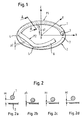
- This game is zero at the ends respectively bearing 3 and 4.
- this game is variable with the compression load of the spring and is generally between a few tenths of a millimeter and about two millimeters.
- the second bridge P2 which has a central game noted p2.
- the second support noted 4 is generally between 150 and 190 ° counted in the counterclockwise direction from the X axis. This angle may vary slightly during compression and this should be taken into account for if you want to build a specific support zone.
- the third support marked 5 is generally between 220 and 300 ° from the X axis
- the figure 2 shows the evolution of the following elevation Z of the clearance between the wire 1 and the cup 2 at the level of the section AA of the figure 1 .
- the step represented in figure 2a corresponds to the establishment of the spring on its cup 2, the spring is then almost not compressed.
- the only point of support of the spring on its cup is the point 3 which represents the beginning of the thread.
- the indicated clearance za measured along the Z axis, depends on the spring pitch in the free state. As the compression of the spring along its Z axis increases this initial game za decreases to reach a value zb in figure 2b : zb can sometimes temporarily take a null value.
- the spring wire is curved and the force exerted on the spring is not vertical to the wire but along the Z axis the spring needs to find a second fulcrum, which will be the reference 5 of the figure 1 .
- the game zb re-increases in general to take the zc value of the provision 2c.
- the game becomes zd. If we continue the compression of the spring until contiguous turns this game zd can cancel under the influence of the compression of the turns on each other.
- the figure 3 shows the creation of the bridges during the deformation of the wire, the spring being here represented in developed.
- the z axis is a parallel to Z but passing through the end 3 of the yarn and on the abscissa we have the angle corresponding to the developed curvilinear length of the yarn.
- the pressures exerted by the wire on the cup are indicated by hatched areas whose amplitude along an axis opposite to z is proportional to said pressure.
- the bearing pressures at the supports 3, 4 and 5 respectively are not identical.
- the figure 4 is similar to the figure 3 but concerns the case of a spring said to "start with negative pitch".
- the wire 1 instead of applying without play on the cup, only supports in very specific areas and thus between two supports a bridge P1
- the figure 5 shows this phenomenon of jumper in the case of a spring-cup system according to the present invention that is to say with elastic supports in compression where the spring is supported on the cup.
- the wire 1 of the spring is represented in the form of its developed as in the Figures 3 or 4 . In solid lines, the wire 1 takes the form that it would have if the supports S1, S2 and S3 were rigid. In discontinuous lines is the shape that takes the wire after crushing of these 3 supports under the effect of the axial compression of the spring.
- the support S1 is compressed by a value C1 and is deformed to take the shape S'1.
- the support S2 is compressed by a value C2 and is deformed to take the shape S'2.
- the support S3 compresses a value C3 and deforms to take the pace S'3.
- the values C1, C2 and C3 are functions of the elastomer used and its shape. These parameters are chosen so that the compression strokes C1, C2 and C3 are gradually decreasing and so that the radius of curvature of the wire 1 in the plane of the drawing is as large as possible in the vicinity of the last support, here in the vicinity of the point d 3b support.
- the decrease of the compression strokes C1, C2 and C3 makes it possible to reduce the arrows p1 and p2 which characterize the importance of the bridges respectively P1 and P2.
- the compressed spring is balanced at 1b, 2b and 3b on its supports S'1, S'2 and S'3 respectively. In this state of equilibrium it always has bridges but having smaller arrows respectively p'1 and p'2.
- Part of the work of bending the wire can accumulate an energy in the wire zone located between the supports 1b and 3b.
- the discontinuity of energy accumulation in the vicinity and on either side of the support 3b is reduced compared to a solution not benefiting from the present invention.
- the pseudo-embedding effect of the so-called dead coil is minimized, so that most of the springs break just after the last support. If we number the supports from 1 to N, the support 1 being the first at the end of the wire, it is by allowing the support N-1 to compress and relax more easily than N that it is possible to increase the radius of curvature of the wire in the vicinity of N and to reduce the variation of energy stored between a position just before and just after the support N.
- the figure 6 shows a top view in perspective of a cup 2 on which are arranged 3 supports S1, S2 and S3. These supports can be glued, overmoulded or clipped to the cup 2. They can also be an integral part of the cup 2 if it is elastomeric or in a plastic material. As can be seen in this figure the shape of the supports as well as their height and length can be variable.
- the top of these supports can be horizontal or inclined plane, or provided with a centering groove. The choice of these forms depends on the development of the springs and their centering mode on the cup. The centering device and any cup edges have not been shown here as independent of the present invention.
- the reference S11 corresponds to the end of the first support S1, where the end of the spring wire rests from the beginning of the compression.
- the curvilinear length of the 3 supports S1, S2 and S3 is represented angularly by the angles ⁇ 1, ⁇ 2 and ⁇ 3. This length is such that during the compression of the spring can be made in contact a small angular migration of the spring support zones and thus prevent a spring support is directly on the cup.
- the figure 7 represents another embodiment of the present invention applied to the case of an inclined cup.
- the Z axis is here the axis of the damper in the case of an application to the front suspensions, or the axis in which is made the compression movement of the spring for any other application.
- the support S2 has a V-shaped upper face for better centering the wire.
- Support S3 has an upper surface with two slopes.
Landscapes
- Engineering & Computer Science (AREA)
- Mechanical Engineering (AREA)
- General Engineering & Computer Science (AREA)
- Springs (AREA)
- Table Devices Or Equipment (AREA)
Applications Claiming Priority (1)
| Application Number | Priority Date | Filing Date | Title |
|---|---|---|---|
| FR0705283A FR2919034B1 (fr) | 2007-07-20 | 2007-07-20 | Systeme ressort-coupelle de suspension |
Publications (2)
| Publication Number | Publication Date |
|---|---|
| EP2017098A2 true EP2017098A2 (de) | 2009-01-21 |
| EP2017098A3 EP2017098A3 (de) | 2010-02-24 |
Family
ID=39952310
Family Applications (1)
| Application Number | Title | Priority Date | Filing Date |
|---|---|---|---|
| EP08012845A Withdrawn EP2017098A3 (de) | 2007-07-20 | 2008-07-16 | Schraubendruckfederverbindung |
Country Status (2)
| Country | Link |
|---|---|
| EP (1) | EP2017098A3 (de) |
| FR (1) | FR2919034B1 (de) |
Citations (3)
| Publication number | Priority date | Publication date | Assignee | Title |
|---|---|---|---|---|
| US6149171A (en) | 1999-03-31 | 2000-11-21 | Daimlerchrysler Corporation | Spring isolator for a motor vehicle suspension |
| JP2004162901A (ja) | 2002-06-13 | 2004-06-10 | Allevard Rejna Autosuspensions | サスペンションスプリング用シース |
| US20050051937A1 (en) | 2001-11-27 | 2005-03-10 | Masahiro Umezawa | Compression coil spring device having discontinuous support structure |
Family Cites Families (2)
| Publication number | Priority date | Publication date | Assignee | Title |
|---|---|---|---|---|
| DE4104859C1 (de) * | 1991-02-16 | 1992-07-09 | Dr.Ing.H.C. F. Porsche Ag, 7000 Stuttgart, De | |
| US20040169323A1 (en) * | 2003-02-28 | 2004-09-02 | Bottene Marlon V. | MacPherson strut spring coil mounts |
-
2007
- 2007-07-20 FR FR0705283A patent/FR2919034B1/fr not_active Expired - Fee Related
-
2008
- 2008-07-16 EP EP08012845A patent/EP2017098A3/de not_active Withdrawn
Patent Citations (3)
| Publication number | Priority date | Publication date | Assignee | Title |
|---|---|---|---|---|
| US6149171A (en) | 1999-03-31 | 2000-11-21 | Daimlerchrysler Corporation | Spring isolator for a motor vehicle suspension |
| US20050051937A1 (en) | 2001-11-27 | 2005-03-10 | Masahiro Umezawa | Compression coil spring device having discontinuous support structure |
| JP2004162901A (ja) | 2002-06-13 | 2004-06-10 | Allevard Rejna Autosuspensions | サスペンションスプリング用シース |
Also Published As
| Publication number | Publication date |
|---|---|
| EP2017098A3 (de) | 2010-02-24 |
| FR2919034B1 (fr) | 2012-05-04 |
| FR2919034A1 (fr) | 2009-01-23 |
Similar Documents
| Publication | Publication Date | Title |
|---|---|---|
| EP2280660B1 (de) | Vorrichtung zur dynamischen nachträglichen stabilisierung zur anpassung der anatomischen lordose | |
| CA2274020C (fr) | Suspensions de roue de vehicule utilisant un ressort combine a une armature souple destinee a modifier sa courbe de raideur | |
| EP1577205A1 (de) | Lenker für Fahrräder und Motorräder | |
| WO2014096735A1 (fr) | Amortisseur de torsion pour un dispositif de transmission de couple d'un vehicule automobile | |
| FR2526152A1 (fr) | Projectile a effet cinetique destine a combattre des engins blindes | |
| EP0682961A1 (de) | Abfahrtsski mit doppel wirkender Versteifungs- und/oder Dämpfungsvorrichtung | |
| FR2900869A1 (fr) | Roue a rayons | |
| FR3003803A1 (fr) | Dispositif de butee de suspension et jambe de suspension equipee d'une telle butee | |
| EP0647787A1 (de) | Drehmomentanlaufschwingarm für Motoren von Kraftfahrzeugen | |
| EP0359655A1 (de) | Hydraulisch gedämpfte Lagerbuchsen | |
| FR2487424A1 (fr) | Etai de mine | |
| EP1603778B1 (de) | Stossdämpferanschlag für ein kraftfahrzeug | |
| EP2017098A2 (de) | Schraubendruckfederverbindung | |
| FR2903750A1 (fr) | Palier a coussinet-douille hydraulique avec decouplage acoustique | |
| FR2710021A1 (fr) | Selle perfectionnée. | |
| WO2013057408A1 (fr) | Dispositif support de groupe motopropulseur dans un véhicule | |
| FR2942983A1 (fr) | Presse plieuse pour le pliage de feuilles | |
| EP0265004B1 (de) | Arm zur Aufhängung des Laugenbehälters einer Waschmaschine und derart ausgerüstete Waschmaschine | |
| FR2765933A1 (fr) | Amortisseur d'oscillations de torsion | |
| EP0092470A1 (de) | Dämpfungsvorrichtung für Trommelbremse, Bremsankerplatte mit solcher Vorrichtung und Trommelbremse mit Bremsankerplatte versehen mit einer solchen Vorrichtung | |
| EP1059466B1 (de) | Schwingungsdämpfer mit unausdehnbarem Kabelbegrenzer | |
| EP2020528A1 (de) | Vorrichtung, die als Begrenzungsanschlag einer Fahrzeugfederung dient, insbesondere in einem Stoßdämpfer, und eine solche Vorrichtung umfassendes Federungssystem | |
| EP3050776A1 (de) | Servolenkstange, die eine rückholfeder umfasst, die mit einer dämpfenden elastomerbeschichtung ausgestattet ist | |
| FR2938618A1 (fr) | Ressort de torsion a raideur multiple | |
| EP0533586B1 (de) | Elastische Aufhängungsvorrichtung mit verschiedenen Steifheiten zur Lagerung eines Geräts |
Legal Events
| Date | Code | Title | Description |
|---|---|---|---|
| PUAI | Public reference made under article 153(3) epc to a published international application that has entered the european phase |
Free format text: ORIGINAL CODE: 0009012 |
|
| AK | Designated contracting states |
Kind code of ref document: A2 Designated state(s): AT BE BG CH CY CZ DE DK EE ES FI FR GB GR HR HU IE IS IT LI LT LU LV MC MT NL NO PL PT RO SE SI SK TR |
|
| AX | Request for extension of the european patent |
Extension state: AL BA MK RS |
|
| PUAL | Search report despatched |
Free format text: ORIGINAL CODE: 0009013 |
|
| AK | Designated contracting states |
Kind code of ref document: A3 Designated state(s): AT BE BG CH CY CZ DE DK EE ES FI FR GB GR HR HU IE IS IT LI LT LU LV MC MT NL NO PL PT RO SE SI SK TR |
|
| AX | Request for extension of the european patent |
Extension state: AL BA MK RS |
|
| 17P | Request for examination filed |
Effective date: 20100427 |
|
| 17Q | First examination report despatched |
Effective date: 20100527 |
|
| AKX | Designation fees paid |
Designated state(s): DE ES FR |
|
| STAA | Information on the status of an ep patent application or granted ep patent |
Free format text: STATUS: THE APPLICATION IS DEEMED TO BE WITHDRAWN |
|
| 18D | Application deemed to be withdrawn |
Effective date: 20110629 |