EP2017017B1 - Rolling roll, rolling mill and rolling method - Google Patents
Rolling roll, rolling mill and rolling method Download PDFInfo
- Publication number
- EP2017017B1 EP2017017B1 EP07742772.2A EP07742772A EP2017017B1 EP 2017017 B1 EP2017017 B1 EP 2017017B1 EP 07742772 A EP07742772 A EP 07742772A EP 2017017 B1 EP2017017 B1 EP 2017017B1
- Authority
- EP
- European Patent Office
- Prior art keywords
- roll
- rolls
- curve
- crown
- function
- Prior art date
- Legal status (The legal status is an assumption and is not a legal conclusion. Google has not performed a legal analysis and makes no representation as to the accuracy of the status listed.)
- Active
Links
Images


Classifications
-
- B—PERFORMING OPERATIONS; TRANSPORTING
- B21—MECHANICAL METAL-WORKING WITHOUT ESSENTIALLY REMOVING MATERIAL; PUNCHING METAL
- B21B—ROLLING OF METAL
- B21B27/00—Rolls, roll alloys or roll fabrication; Lubricating, cooling or heating rolls while in use
- B21B27/02—Shape or construction of rolls
-
- B—PERFORMING OPERATIONS; TRANSPORTING
- B21—MECHANICAL METAL-WORKING WITHOUT ESSENTIALLY REMOVING MATERIAL; PUNCHING METAL
- B21B—ROLLING OF METAL
- B21B13/00—Metal-rolling stands, i.e. an assembly composed of a stand frame, rolls, and accessories
- B21B13/14—Metal-rolling stands, i.e. an assembly composed of a stand frame, rolls, and accessories having counter-pressure devices acting on rolls to inhibit deflection of same under load; Back-up rolls
- B21B13/142—Metal-rolling stands, i.e. an assembly composed of a stand frame, rolls, and accessories having counter-pressure devices acting on rolls to inhibit deflection of same under load; Back-up rolls by axially shifting the rolls, e.g. rolls with tapered ends or with a curved contour for continuously-variable crown CVC
-
- B—PERFORMING OPERATIONS; TRANSPORTING
- B21—MECHANICAL METAL-WORKING WITHOUT ESSENTIALLY REMOVING MATERIAL; PUNCHING METAL
- B21B—ROLLING OF METAL
- B21B13/00—Metal-rolling stands, i.e. an assembly composed of a stand frame, rolls, and accessories
- B21B13/14—Metal-rolling stands, i.e. an assembly composed of a stand frame, rolls, and accessories having counter-pressure devices acting on rolls to inhibit deflection of same under load; Back-up rolls
-
- B—PERFORMING OPERATIONS; TRANSPORTING
- B21—MECHANICAL METAL-WORKING WITHOUT ESSENTIALLY REMOVING MATERIAL; PUNCHING METAL
- B21B—ROLLING OF METAL
- B21B27/00—Rolls, roll alloys or roll fabrication; Lubricating, cooling or heating rolls while in use
- B21B27/02—Shape or construction of rolls
- B21B27/021—Rolls for sheets or strips
-
- B—PERFORMING OPERATIONS; TRANSPORTING
- B21—MECHANICAL METAL-WORKING WITHOUT ESSENTIALLY REMOVING MATERIAL; PUNCHING METAL
- B21B—ROLLING OF METAL
- B21B37/00—Control devices or methods specially adapted for metal-rolling mills or the work produced thereby
- B21B37/28—Control of flatness or profile during rolling of strip, sheets or plates
- B21B37/42—Control of flatness or profile during rolling of strip, sheets or plates using a combination of roll bending and axial shifting of the rolls
-
- B—PERFORMING OPERATIONS; TRANSPORTING
- B21—MECHANICAL METAL-WORKING WITHOUT ESSENTIALLY REMOVING MATERIAL; PUNCHING METAL
- B21B—ROLLING OF METAL
- B21B27/00—Rolls, roll alloys or roll fabrication; Lubricating, cooling or heating rolls while in use
- B21B27/02—Shape or construction of rolls
- B21B27/021—Rolls for sheets or strips
- B21B2027/022—Rolls having tapered ends
Definitions
- the present invention relates to a roll, a rolling mill and a rolling method, in rolling a metal plate as material, either in hot or cold processes, correcting the plate crown etc.
- the deflection of the roll caused by the rolling load may often generate the so-called plate crown: a phenomenon that the thickness of the part near the center (in the width direction) of the plate becomes greater than that of the part near the end (in the width direction) of the plate.
- the rolling mill has the upper and lower work-rolls (or intermediate rolls or backup rolls) which are provided with an S-shaped roll crown, which may be called CVC or others, on the periphery, as shown in FIG. 8 , and the pair of rolls relatively move (or shift against each other) in the axial direction.
- the relative movement of the pair of rolls corresponding to the plate width, profile and others can varies a roll gap properly, as shown in FIGS. 8(a) - 8(c) , thereby correcting the plate crown.
- Another art of correcting the plate crown by means of the rolls in the similar roll-crown periphery is disclosed in the patent bibliography 2.
- the rolls used in the rolling mills as described in the patent bibliography 1 and 2 have roll-crown curves or roll profiles, such as an example shown in Fig. 6 .
- the whole curve of the roll-crown periphery in such rolls can be drawn as a simple curve of those functions as cubic function or sine function of the axial length of the roll (or the position in the barrel length).
- the gaps between the rolls at the surface are distributed as shown in Fig. 7 . If the width of the metal plate as material is the narrower, the rolls near the center will receive the heavier load and the more deflection, hence the shift length for the rolls should be increased in the direction as shown in Fig.
- patent bibliography 5 describes other method of rolling, using the work-rolls shaped convergent or taper-ground at one end of the flat rolls without roll-crown, positioning this convergent part to one side of the plate material to be rolled.
- This bibliography states that this method reduces the contact pressure between such convergent part and the plate material so that the edge-drops, which will be explained below, at the edge of the plate are reduced.
- the arts in the patent bibliographies 1 and 2 may correct the plate crown through the action by the roll crown, but will not correct the plate edge state such as the edge-drop (a phenomenon in the plate that the edge hangs down to lose the corner and the plate thickness becomes thinner.)
- the plate crown is corrected over the whole range of the plate in the lateral direction, as shown in Fig. 8 .
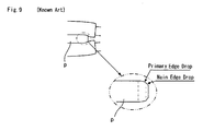
- the edge drop at the edges of the plate width is inevitable because of the local constraint by the work-rolls, as shown in Fig. 9 .
- the invention according to the claims provides a roll, a rolling mill and a rolling method capable of not only effectively correcting the plate crown of a material to be rolled but also reducing the edge drop and preventing a roll from damage caused by the increase of the local line pressure between the rolls.
- a continuously varying roll gap is formed between the central regions between the local minimum point and the local maximum point (the curving part representing one function mentioned above), which functions for the control of the crown. That is, as well as the rolling mill illustrated in Fig. 8 , proper determination of the axial, relative position of the pair of rolls can determine the proper roll gap and correct the plate crown.
- a curving part with a radius more sharply decreasing toward the end of the roll is formed by the function having an inclination of steeper gradient than that in the central region.
- the roll gap is even over almost the entire range of the plate width of 1200 mm) and a minus crown having a roll gap smaller toward the end of the plate in the width direction, contrary to the general.
- the roll can correct the plate crown properly under variety of rolling conditions in a wide range.
- the end region from the local minimum point to the nearer roll end has a curving part with a gently increasing radius toward the roll end, which is formed by a function having an inclination of gentler gradient than that of the function in the central region. Because of the gently increasing radius, the line contacting pressure against the other rolls around this region hardly increases excessively. Therefore, the inconvenient events such as occurring of spalling and other local damage of the roll and the exchange of rolls in a short term are avoidable. It should be noted that also this action applies to every case that the roll of the invention is used as the work-roll, intermediate roll or backup roll of a rolling mill.
- a rolling mill of the invention according to the claim is capable of correcting the crown of a material to be rolled by relatively moving a pair of upper and lower rolls in the axial direction which are respectively provided with a roll crown and point-symmetrical regarding the cross-sectional center of the material to be rolled, and characterized in that any of the rolls described above is disposed as the pair of rolls (a pair of work-rolls, intermediate rolls or backup rolls).
- the rolling mill can properly correct the plate crown and reduce the edge drop. Further the roll bending can be effectively executed; therefore the rolling mill has a considerably high capability of correcting the plate crown. Since the inconvenient increase of the line contacting pressure with other rolls is avoidable, damage to the roll due to spalling etc. hardly occurs.
- the roll is disposed as a pair of work-rolls. Because by forming the roll crown on the work-roll which contacts with a material to be rolled, the work-roll can directly exert the function of correcting the plate crown and of reducing the edge drop on the material to be rolled and bring about the remarkable effects. Even when the rolling load is small, the function acts easily too.
- the roll is disposed as a pair of intermediate rolls.
- the rolling mill has the proper roll gap formed between the work-rolls according to the roll crown of the roll and further has the part of the enlarged gap where the constraining force is loosened, thereby exerting the function of correcting the plate crown and reducing the edge drop.
- the roll is disposed as the intermediate roll like this, further advantageously the roll bending can be effectively exerted on the work-roll.
- the roll can be disposed also as a pair of backup rolls.
- This case also has the same merits as described above and in particular further has the following effect: since a flat and plane roll can be used as the work-roll, the surface properties of a material to be rolled is easily heightened; therefore it is easy to answer the required quality as a four-high mill for aluminum plate and raw tinplate and other mills. Moreover, since the roll is generally applied to the backup roll of a four-high mill, advantageously the number of rolls is less than that of a six-high mill.
- the work-roll or the intermediate roll is preferably provided with a bending mechanism. Whether the roll (work-roll or intermediate roll) to be provided with the bending mechanism has the roll crown described above is not a problem. Bending the work-roll or intermediate roll by the bending mechanism can compensate the capability of the roll crown to correct the plate crown. In detail, even when the roll gap is set by determining the axial, relative position of the pair of rolls having the roll crown, occasionally the plate is not sufficiently corrected according to the properties of a material to be rolled and the amount of rolling load corresponding to it: in these cases, exerting roll bending on the work-roll or intermediate roll by the bending mechanism can correct the plate crown more properly.
- the function in the central region and the function from the local maximum point to the nearer roll end are determined so that: when the axial, relative position of the pair of rolls is determined so as to form a roll gap corresponding to the plate width of the material to be rolled (that is, a roll gap suitable to correct the plate crown regarding the material to be rolled with the plate width) by using the pair of rolls, the end region from the local maximum point to the nearer roll end of the roll crown is positioned to one of the upper and lower positions holding the end of the width direction of the material to be rolled.
- the pair of rolls can be the work-rolls, the intermediate rolls of a six-high mill and the backup rolls of a four-high mill or six-high mill.
- this rolling mill when the relative position of the pair of rolls in the axial direction is determined so as to be able to correct the plate crown corresponding to the plate width of the material to be rolled, the end region from the local maximum point to the nearer roll end is placed at the position holding the end of the width direction of the material to be rolled. As the end region has the enlarged gap as described above where the constraining force is loosened, the above positional relationship causes to reduce the edge drop at the end of the width direction of the material to be rolled and effectively bend the work-roll or intermediate roll.
- the rolling mill can effectively reduce the edge drop at the same time when the relative position of the rolls is determined for correcting the plate crown.
- the relative position of the rolls in the axial direction is determined so as to form a roll gap suitable for correcting the plate crown corresponding to the plate width of the material to be rolled.
- either of the upper or lower position holding the end of the width direction of the material to be rolled is preferably placed in the part having a proper amount (measurement) of the enlarged gap and the properly loosened constraining force.
- a rolling method of the claim is characterized by using the rolling mill described above to roll after relatively move the rolls each other in the axial direction so that the end region from the local maximum point to the nearer roll end of the roll crown (in particular preferably the part having a proper amount of gap enlargement) is placed to one of the upper and lower positions holding the end of the width direction of a material to be rolled.
- the proper rolling can be executed by simply determining the axial position of the roll in relation to the position of the end of the width direction of a material to be rolled as described above.
- a rolling mill using the roll of the invention as a pair of work-rolls in a four-high mill is shown in Fig. 1 - Fig. 5 .
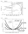
- Fig.1 shows a roll curve of the roll 1 and 2 (See Fig. 3 , for example) which is formed according to the invention.
- Fig. 1 shows a roll curve of the roll 1 and 2 (See Fig. 3 , for example) which is formed according to the invention.
- Fig. 2 is a chart showing a roll gap distribution between the rolls 1 and 2 when the rolls 1 and 2 with the curve of Fig. 1 are disposed in point
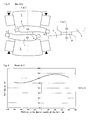
- FIG. 3 is an illustration showing the relative position of the rolls 1 and 2 and the roll gap distribution when the rolls 1 and 2 are shifted toward the minus direction in order to roll a material to be rolled (a steel plate) p with a comparatively wide width ( Fig. 3(b) ) and is an illustration showing the plate crown etc, while loaded by the rolling mill ( Fig. 3(a)).
- Figs. 4(a) and 4(b) are illustrations showing the same when the rolls 1 and 2 are shifted slightly toward the plus direction in order to roll a material to be rolled p with a medium width; and Figs.
- 5(a) and 5(b) are illustrations showing the same when the rolls 1 and 2 are shifted largely toward the plus direction in order to roll a material to be rolled p with a considerably narrow width. While the illustrated rolling mill is a four-high mill where the backup rolls 3 and 4 with a large diameter are arranged in the back of the work-rolls adapting the rolls 1 and 2, it is obvious that the invention is not to be considered limited to it.
- a roll crown comprising a continuous curve having a local maximum point and a local minimum point is formed as shown in Fig. 1 .
- the relation between the roll radius and the barrel length of the roll at each point of the roll crown is determined by not one function over the entire barrel length but three functions each of them being adapted to the different region of the barrel divided into three regions as follows: a) the central region from the local minimum point and the local maximum point adapting a cosine function including the local minimum point and the local maximum point; b) the end region from the local maximum point to the nearer roll end illustrated in the right side of Fig.
- Fig. 1 adapting a quadratic function with an inclination of steeper gradient than that according to the cosine function (or the inclination illustrated by the broken line); and c) the end region from the local minimum point to the nearer roll end illustrated in the left side of Fig. 1 adapting a quadratic function with an inclination of gentler (almost zero) gradient than that according to the cosine function (or the inclination illustrated by the broken line).
- the local maximum point, the local minimum point, the central region, the end region (from the local maximum point) and the end region (from the local minimum point) of Fig.1 are indicated respectively by reference letters 11, 12, 13, 14 and 15 in the roll 1 of Fig. 3(b) .
- a proper roll gap is formed between the rolls 1 and 2 by the central region 13 of the roll crown, and thus it becomes possible to properly correct and flatten the plate crown of a material to be rolled p.
- the roll gap distribution viewed from the width direction of the material to be rolled p when the relative position of the rolls 1 and 2 is determined corresponding to each plate width is shown in Fig. 2 ; and the rough form (or the exaggerated illustration) of the roll gap in that case is shown in Fig. 3(b) - FIG. 5(b) .
- the narrower the width of the metal to be rolled p is, the more concentrically the rolls 1 and 2 are loaded and more easily deflected; therefore the roll gap is formed so that the part near the center is smaller than the end in the width direction.
- the rolls 1 and 2 have, in the end region 14 from the local maximum point 11 to the nearer roll end, the inclined part where the roll radius decreases sharply, a part where the roll gap, illustrated in Fig. 2 , Fig. 3 , etc., is enlarged or a loose-constraining part in other words is formed from the local maximum point 11 to the roll end.
- the loose-constraining part exists between the rolls 1 and 2 and the material to be rolled p and also between the rolls 1 and 2 and the backup rolls 3 and 4, where the contacting pressure with each other gradually decreases toward the roll end.
- the constraint of the material to be rolled p is loosened, when placing the end (edge) of the width direction of the material to be rolled p, it is possible to effectively reduce the edge drop. Further in this part, the constraint of the work-roll (or the intermediate roll when the rolling mill is a six-high mill) is loosened; therefore, it is possible to exert sufficient roll bending on the roll to correct the plate crown more properly.
- the constraint in the loose-constraining part dose not sharply decreases to zero at the roll end, the line pressure between rolls in other part is prevented from excessively increasing to cause spalling and other damage of the roll.
- the mill modulus and lateral rigidity of the mill are prevented from decreasing with shifting of the roll.
- the rolls 1 and 2 also have the part with an inclination of gentle gradient in the end region 15 from the local minimum point 12 to the nearer roll end. Accordingly, even when rolling is done as shown in FIGS. 3(a) and 3(b) for example, the line contacting pressure between the rolls 1 and 2 and the backup rolls 3 and 4 is prevented from increasing excessively near the end region 15 and the inconvenience that the roll is easily damaged due to spalling etc. is avoidable.
- the roll crown in the central region 13 is properly formed by a preferable function, it is possible to correct the plate crown of the material to be rolled p by shifting the rolls 1 and 2 in the axial direction a) to increase the horizontal distance between each local maximum point 1 of the rolls 1 and 2 when the plate width is large (See Fig. 3 ), or b) to decrease the horizontal distance so as to bring the outwardly convex part of the roll curve close to each other when the plate width is narrow.
- the function is set so that the edge part of the material to be rolled p is preferably positioned to just outside of the local maximum point 11 (or the end region), the rolls 1 and 2 are able to be used to correct the plate crown and also reduce the edge drop.
- L be a barrel length
- a the distance of the local maximum point from the center of the barrel length of the roll
- b the distance of the local minimum point from the end of the barrel length of the roll
- A the difference of the radius of the local maximum point and the local minimum point.
- c is a constant to determine the gentleness of the curve.
- d is a constant to determine the steepness of the curve.
- This roll is used for the upper work-roll and a curve of point-symmetric with the roll regarding the cross-sectional center of the plate is disposed to the lower work-roll.
- the curve shown in Fig. 2 is obtained by relatively shifting the rolls by ⁇ 100 mm in the axial direction.
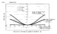
- the roll curve where the barrel length of the roll is uniformly represented by a cosine function which is one of the conventional arts, is shown in Fig. 6 and the roll gap formed with it is shown in Fig. 7 .
- the same maximum value and minimum value is used as in the present invention for comparison to the present invention.
- Fig.2 and Fig. 7 in this invention, when the upper and lower rolls are relatively moved in the axial direction to the roll position for obtaining a roll crown according to the plate width, a loose-constraining part of the roll is automatically generated in the roll gap near the end of the plate width. Consequently, the end of the plate width is constrained in a better condition that makes it possible to correct the plate crown and has potential at the same time for improving the bending effect and for the edge drop reducing effect.
- the roll, rolling mill and rolling method of the invention is effectively applicable in the industrial field executing hot or cold rolling of a metal plate as a material to be rolled.
Landscapes
- Engineering & Computer Science (AREA)
- Mechanical Engineering (AREA)
- Physics & Mathematics (AREA)
- Geometry (AREA)
- Reduction Rolling/Reduction Stand/Operation Of Reduction Machine (AREA)
- Casting Or Compression Moulding Of Plastics Or The Like (AREA)
- Control Of Metal Rolling (AREA)
- Rolls And Other Rotary Bodies (AREA)
Description
- The present invention relates to a roll, a rolling mill and a rolling method, in rolling a metal plate as material, either in hot or cold processes, correcting the plate crown etc.
- When rolling metal plate by means of a rolling mill, the deflection of the roll caused by the rolling load may often generate the so-called plate crown: a phenomenon that the thickness of the part near the center (in the width direction) of the plate becomes greater than that of the part near the end (in the width direction) of the plate.
- One of rolling mills capable of correcting the plate crown is disclosed in the
patent document 1. The rolling mill has the upper and lower work-rolls (or intermediate rolls or backup rolls) which are provided with an S-shaped roll crown, which may be called CVC or others, on the periphery, as shown inFIG. 8 , and the pair of rolls relatively move (or shift against each other) in the axial direction. The relative movement of the pair of rolls corresponding to the plate width, profile and others can varies a roll gap properly, as shown inFIGS. 8(a) - 8(c) , thereby correcting the plate crown.
Another art of correcting the plate crown by means of the rolls in the similar roll-crown periphery is disclosed in thepatent bibliography 2. - The rolls used in the rolling mills as described in the
patent bibliography Fig. 6 . In other words, the whole curve of the roll-crown periphery in such rolls can be drawn as a simple curve of those functions as cubic function or sine function of the axial length of the roll (or the position in the barrel length). For the rolling mill which uses work-rolls with such roll-crown curve, the gaps between the rolls at the surface are distributed as shown inFig. 7 . If the width of the metal plate as material is the narrower, the rolls near the center will receive the heavier load and the more deflection, hence the shift length for the rolls should be increased in the direction as shown inFig. 8 (c) (a plus shifting (S > 0)). On the other hand, if the width of the metal plate material is the wider, the rolls will receive widely distributed load and the deflection will be the less, hence the shift length for the rolls should be increased in the reverse direction as shown inFig. 8 (b) (a minus shifting (S < 0)). Thus the proper shift amount of the rolls varies according to the plate material widths, and the settings of the roll-gaps should be adjusted according to the plate product widths as shown inFig. 7 . - The other example of correcting method of the plate-crown is the art shown in the
patent bibliography 3. This bibliography describes (particularly as shown inFig. 2 ) a six-high mill, or so-called an HC mill or others, which has a pair of flat (without roll-crowns) rolls, as the upper and lower intermediate rolls, and they are mobile in their axial directions. By moving these intermediate rolls in their axial directions, the edges of the flat rolls will be positioned at the end of the plate product to enhance the bending effectiveness in the work-rolls, thereby correcting the plate-crown.
Another example of such mill, applying rolls with an S-shaped roll-crown in place of the flat rolls above-mentioned, is shown in thebibliography 4. - In addition, the patent bibliography 5 describes other method of rolling, using the work-rolls shaped convergent or taper-ground at one end of the flat rolls without roll-crown, positioning this convergent part to one side of the plate material to be rolled. This bibliography states that this method reduces the contact pressure between such convergent part and the plate material so that the edge-drops, which will be explained below, at the edge of the plate are reduced.
- Patent Bibliography 1:
JP A S57-91807 - Patent Bibliography 2:
JP A 2001-252705 - Patent Bibliography 3:
JP B S62-1 0722 - Patent Bibliography 4:
JP A S63-30104 - Patent Bibliography 5:
JP A S55-77903 - The arts in the
patent bibliographies Fig. 8 . However, the edge drop at the edges of the plate width is inevitable because of the local constraint by the work-rolls, as shown inFig. 9 . In addition, when backup rolls are used, the end part of the work-rolls are in contact with, and constrained by, the backup rolls, therefore, it is impossible to correct the plate crown by exerting a strong roll bending. Moreover, since one end of the S-shaped roll crown has a part of increasing roll diameter (the part shown as # ofFig. 8 ), the line contacting pressure against the backup rolls in a four-high mill or a six-high mill may increase excessively to cause a local spalling etc. which may damage the roll and shorten the roll life. - The art of the
patent bibliography - The art of the patent bibliography 5 is effective to decrease the edge drop but has a lower capability of correcting the crown over the entire plate width; therefore, in order to sufficiently correct the plate crown it is necessary to prepare other means such as an intermediate roll having an S-shaped roll crown, or a high-capacity bender, etc.
- The invention according to the claims provides a roll, a rolling mill and a rolling method capable of not only effectively correcting the plate crown of a material to be rolled but also reducing the edge drop and preventing a roll from damage caused by the increase of the local line pressure between the rolls.
- The objects of the invention are solved by the subject matter of the independent claim. Further improvements are given by the subject matter of the dependent claims.
Rolls of the invention according to the claims are characterized in that: - Roll crown periphery is formed by a continuous curve (a curve continuously smooth overall) with a local maximum point and a local minimum point;
- The central region of the curve between the local maximum point and the local minimum point represents one function; and
- The end region of the curve from the local maximum point to the nearer roll end represents another function having an inclination of steeper gradient (or having a radius decreasing more sharply toward the roll end) than that of the extension of the function in the central region.
- Regarding this roll, when a pair of such rolls is disposed to the upper and lower positions point-symmetric in the same plane as shown in
Fig. 3(b) , a continuously varying roll gap is formed between the central regions between the local minimum point and the local maximum point (the curving part representing one function mentioned above), which functions for the control of the crown. That is, as well as the rolling mill illustrated inFig. 8 , proper determination of the axial, relative position of the pair of rolls can determine the proper roll gap and correct the plate crown.
On the other hand, in the end region from the local maximum point to the nearer roll end, a curving part with a radius more sharply decreasing toward the end of the roll is formed by the function having an inclination of steeper gradient than that in the central region. Consequently an enlarged gap is generated in this region, which continues to the roll gap formed in the central region described above. In this end region, the constraining force (or contact strength) between the roll and the material to be rolled or other roll (any of the work-roll, intermediate roll and backup roll) is loosened; therefore, positioning the end in the width direction of the material to be rolled in this end region can reduce the edge drop regarding the material to be rolled and also exert a sufficient roll bending on the material to be rolled. It should be noted that the roll according to the claims, which is used as the work-roll inFigs. 3(a), 3(b) , etc., can loosen the constraining force in the same region and exert the same effect also when used as the intermediate roll of a six-high mill and the backup roll of a four-high mill or six-high mill.
As described above, the use of the roll can not only correct the plate crown properly but also reduce the edge drop at the same time, and exert a roll bending effectively according to need.
It should be noted that as the roll adapts the curve having a local maximum point and local minimum point, it is possible, when a material to be rolled has a wide width, to realize a zero crown having an even roll gap over the entire range in the width direction (indicated by "Crown for Wide Width, S = - 100 mm" inFig. 2 , for example: the roll gap is even over almost the entire range of the plate width of 1200 mm) and a minus crown having a roll gap smaller toward the end of the plate in the width direction, contrary to the general. As a result, the roll can correct the plate crown properly under variety of rolling conditions in a wide range. - Further, in the roll of the invention, it is preferable that:
- in the end region from the local minimum of gentler gradient than that of the extension of the function in the central region (that is, a function having a radius increasing more gently toward the roll end or having a constant radius).
- Regarding this roll, the end region from the local minimum point to the nearer roll end has a curving part with a gently increasing radius toward the roll end, which is formed by a function having an inclination of gentler gradient than that of the function in the central region. Because of the gently increasing radius, the line contacting pressure against the other rolls around this region hardly increases excessively. Therefore, the inconvenient events such as occurring of spalling and other local damage of the roll and the exchange of rolls in a short term are avoidable. It should be noted that also this action applies to every case that the roll of the invention is used as the work-roll, intermediate roll or backup roll of a rolling mill.
- With regard to the roll of the invention, it is preferable that:
- the central region represents (a curve of) a cosine function and the end region from the local maximum point or the end region from the local minimum point also represents (a curve of) a quadratic function, for example.
- A rolling mill of the invention according to the claim is capable of correcting the crown of a material to be rolled by relatively moving a pair of upper and lower rolls in the axial direction which are respectively provided with a roll crown and point-symmetrical regarding the cross-sectional center of the material to be rolled, and characterized in that any of the rolls described above is disposed as the pair of rolls (a pair of work-rolls, intermediate rolls or backup rolls).
By the action of the rolls mentioned above, the rolling mill can properly correct the plate crown and reduce the edge drop. Further the roll bending can be effectively executed; therefore the rolling mill has a considerably high capability of correcting the plate crown. Since the inconvenient increase of the line contacting pressure with other rolls is avoidable, damage to the roll due to spalling etc. hardly occurs. - Regarding such a rolling mill, particularly it is preferable that the roll is disposed as a pair of work-rolls. Because by forming the roll crown on the work-roll which contacts with a material to be rolled, the work-roll can directly exert the function of correcting the plate crown and of reducing the edge drop on the material to be rolled and bring about the remarkable effects. Even when the rolling load is small, the function acts easily too.
- Otherwise, it is also preferable that the roll is disposed as a pair of intermediate rolls. In this case also, the rolling mill has the proper roll gap formed between the work-rolls according to the roll crown of the roll and further has the part of the enlarged gap where the constraining force is loosened, thereby exerting the function of correcting the plate crown and reducing the edge drop. In the case where the roll is disposed as the intermediate roll like this, further advantageously the roll bending can be effectively exerted on the work-roll.
It should be noted that the roll can be disposed also as a pair of backup rolls. This case also has the same merits as described above and in particular further has the following effect: since a flat and plane roll can be used as the work-roll, the surface properties of a material to be rolled is easily heightened; therefore it is easy to answer the required quality as a four-high mill for aluminum plate and raw tinplate and other mills. Moreover, since the roll is generally applied to the backup roll of a four-high mill, advantageously the number of rolls is less than that of a six-high mill. - Regarding the rolling mill of the invention mentioned above, the work-roll or the intermediate roll is preferably provided with a bending mechanism. Whether the roll (work-roll or intermediate roll) to be provided with the bending mechanism has the roll crown described above is not a problem.
Bending the work-roll or intermediate roll by the bending mechanism can compensate the capability of the roll crown to correct the plate crown. In detail, even when the roll gap is set by determining the axial, relative position of the pair of rolls having the roll crown, occasionally the plate is not sufficiently corrected according to the properties of a material to be rolled and the amount of rolling load corresponding to it: in these cases, exerting roll bending on the work-roll or intermediate roll by the bending mechanism can correct the plate crown more properly. - Regarding the rolling mill of the invention, particularly it is preferable that the function in the central region and the function from the local maximum point to the nearer roll end are determined so that: when the axial, relative position of the pair of rolls is determined so as to form a roll gap corresponding to the plate width of the material to be rolled (that is, a roll gap suitable to correct the plate crown regarding the material to be rolled with the plate width) by using the pair of rolls, the end region from the local maximum point to the nearer roll end of the roll crown is positioned to one of the upper and lower positions holding the end of the width direction of the material to be rolled. It should be noted that the pair of rolls can be the work-rolls, the intermediate rolls of a six-high mill and the backup rolls of a four-high mill or six-high mill.
According to this rolling mill, when the relative position of the pair of rolls in the axial direction is determined so as to be able to correct the plate crown corresponding to the plate width of the material to be rolled, the end region from the local maximum point to the nearer roll end is placed at the position holding the end of the width direction of the material to be rolled. As the end region has the enlarged gap as described above where the constraining force is loosened, the above positional relationship causes to reduce the edge drop at the end of the width direction of the material to be rolled and effectively bend the work-roll or intermediate roll. That is, the rolling mill can effectively reduce the edge drop at the same time when the relative position of the rolls is determined for correcting the plate crown. On the other hand, by simply placing the end region of the roll to one of the position holding the end of the width direction of the material to be rolled so as to reduce the edge drop, the relative position of the rolls in the axial direction is determined so as to form a roll gap suitable for correcting the plate crown corresponding to the plate width of the material to be rolled.
It should be noted that, when the axial, relative position of the rolls is determined, either of the upper or lower position holding the end of the width direction of the material to be rolled is preferably placed in the part having a proper amount (measurement) of the enlarged gap and the properly loosened constraining force. For this purpose, it is desirable to properly determine also the function with the inclination of steep gradient provided to the end region. In addition, it is further preferable to determine the function of the end region considering that the part where the constraining force is loosened is formed so that a necessary roll bending can be exerted corresponding to the amount of the rolling load. - A rolling method of the claim is characterized by using the rolling mill described above to roll after relatively move the rolls each other in the axial direction so that the end region from the local maximum point to the nearer roll end of the roll crown (in particular preferably the part having a proper amount of gap enlargement) is placed to one of the upper and lower positions holding the end of the width direction of a material to be rolled.
According to this rolling method, the proper rolling can be executed by simply determining the axial position of the roll in relation to the position of the end of the width direction of a material to be rolled as described above. Because when the axial position of the roll is determined in such a way, a proper roll gap capable of correcting the plate crown is formed between a pair of rolls; consequently both the correction of the plate crown and the reduction of the edge drop are executed at the same time. Unless the plate crown is sufficiently corrected when determining the axial position of the roll in this way, it is desirable to compensate the correction by bending the work-roll or intermediate roll. -
-
Fig. 1 shows a roll curve of the roll which is formed according to the invention; -
Fig. 2 shows a roll gap distribution when the rolls with the curve ofFig. 1 are disposed in point-symmetric to the upper and lower positions and respectively shifted in the axial direction corresponding to the plate width; -
Fig. 3(b) is an illustration showing the relative position of therolls rolls Fig. 3(a) is an illustration showing the plate crown etc, while rolling; -
Fig. 4(b) is an illustration showing the relative position of therolls rolls Fig. 4(a) is an illustration showing the plate crown etc, while rolling; -
Fig. 5(b) is an illustration showing the relative position of therolls rolls Fig. 5(a) is an illustration showing the plate crown etc, while rolling; -
Fig. 6 shows a roll curve of a conventional roll; -
Fig. 7 shows a roll gap when using the roll ofFig. 6 ; -
Fig. 8 is an illustration showing a conventional rolling mill:Fig. 8(a) shows the zero-shifting state when a roll is not shifted in the axial direction,Fig. 8(b) shows the minus-shifting state, andFig. 8(c) shows the plus-shifting state; and -
Fig. 9 is a conceptual view showing the edge drop of a material to be rolled p easily occurring in a conventional rolling mill. -
- 1 and 2: Roll
- 3 and 4: Backup Roll
- 11: Local Maximum Point
- 12: Local Minimum Point
- 13: Central Region
- 14: End Region (from the Local Maximum Point)
- 15: End Region (from the Local Minimum Point)
- P: Material to Be Rolled
- As one embodiment of the invention, a rolling mill using the roll of the invention as a pair of work-rolls in a four-high mill is shown in
Fig. 1 - Fig. 5 .Fig.1 shows a roll curve of theroll 1 and 2 (SeeFig. 3 , for example) which is formed according to the invention.Fig. 2 is a chart showing a roll gap distribution between therolls rolls Fig. 1 are disposed in point-symmetric to the upper and lower positions and eachroll Fig. 3 is an illustration showing the relative position of therolls rolls Fig. 3(b) ) and is an illustration showing the plate crown etc, while loaded by the rolling mill (Fig. 3(a)). Figs. 4(a) and 4(b) are illustrations showing the same when therolls Figs. 5(a) and 5(b) are illustrations showing the same when therolls
While the illustrated rolling mill is a four-high mill where the backup rolls 3 and 4 with a large diameter are arranged in the back of the work-rolls adapting therolls - In the barrel of the
roll Fig. 1 . However, the relation between the roll radius and the barrel length of the roll at each point of the roll crown is determined by not one function over the entire barrel length but three functions each of them being adapted to the different region of the barrel divided into three regions as follows: a) the central region from the local minimum point and the local maximum point adapting a cosine function including the local minimum point and the local maximum point; b) the end region from the local maximum point to the nearer roll end illustrated in the right side ofFig. 1 adapting a quadratic function with an inclination of steeper gradient than that according to the cosine function (or the inclination illustrated by the broken line); and c) the end region from the local minimum point to the nearer roll end illustrated in the left side ofFig. 1 adapting a quadratic function with an inclination of gentler (almost zero) gradient than that according to the cosine function (or the inclination illustrated by the broken line).
The local maximum point, the local minimum point, the central region, the end region (from the local maximum point) and the end region (from the local minimum point) ofFig.1 are indicated respectively byreference letters roll 1 ofFig. 3(b) . - When a pair of
rolls Fig. 3 , and determined each relative position in the axial direction properly, a proper roll gap is formed between therolls central region 13 of the roll crown, and thus it becomes possible to properly correct and flatten the plate crown of a material to be rolled p. The roll gap distribution viewed from the width direction of the material to be rolled p when the relative position of therolls Fig. 2 ; and the rough form (or the exaggerated illustration) of the roll gap in that case is shown inFig. 3(b) - FIG. 5(b) . The narrower the width of the metal to be rolled p is, the more concentrically therolls - As the
rolls end region 14 from the localmaximum point 11 to the nearer roll end, the inclined part where the roll radius decreases sharply, a part where the roll gap, illustrated inFig. 2 ,Fig. 3 , etc., is enlarged or a loose-constraining part in other words is formed from the localmaximum point 11 to the roll end. In the upper and lower positions of theend region 14, the loose-constraining part exists between therolls rolls
However, as the constraint in the loose-constraining part dose not sharply decreases to zero at the roll end, the line pressure between rolls in other part is prevented from excessively increasing to cause spalling and other damage of the roll. Moreover, because of the same reason, the mill modulus and lateral rigidity of the mill are prevented from decreasing with shifting of the roll. - The
rolls end region 15 from the localminimum point 12 to the nearer roll end. Accordingly, even when rolling is done as shown inFIGS. 3(a) and 3(b) for example, the line contacting pressure between therolls end region 15 and the inconvenience that the roll is easily damaged due to spalling etc. is avoidable. - In order to properly correct the plate crown and reduce the edge drop of the material to be rolled p, it is necessary to hold almost entire width of the material to be rolled p with the
central region 13 in the barrel of therolls maximum point 11. However, proper selection of the function which determines the curve of thecentral region 13 makes the edge part naturally held with the loose-constraining part when the axial, relative position of therolls central region 13 is properly formed by a preferable function, it is possible to correct the plate crown of the material to be rolled p by shifting therolls maximum point 1 of therolls Fig. 3 ), or b) to decrease the horizontal distance so as to bring the outwardly convex part of the roll curve close to each other when the plate width is narrow. In each case, if the function is set so that the edge part of the material to be rolled p is preferably positioned to just outside of the local maximum point 11 (or the end region), therolls - The following description is an example of the roll curve shown in
Fig. 1 .
Let L be a barrel length, a the distance of the local maximum point from the center of the barrel length of the roll, b the distance of the local minimum point from the end of the barrel length of the roll, and A the difference of the radius of the local maximum point and the local minimum point. - When the roll radius f (X') on each point of the surface is composed of a cosine function with amplitude A between the local minimum point and the local maximum point, the roll curve between them is represented by the equations (a) and (2) such as:


- R0: Standard roll radius
- X represents the arbitrary axial position from the end of the roll barrel, but in
Fig. 1 the center is regarded as 0 for convenience of illustrating. - The region from the end of the roll barrel to the local minimum point represents the following quadratic equation with an inclination of gentler gradient than that of the curve represented by the equations (1) and (2):


Here, c is a constant to determine the gentleness of the curve. - While, the region from the local maximum point to the nearer end of the roll barrel represents the following quadratic equation with an inclination of steeper gradient than that of the curve represented by the equations (1) and (2):


Here, d is a constant to determine the steepness of the curve. - The roll curve described above is applied to the work-roll of a four-high mill for rolling the plate of 4 feet width.
Fig. 1 shows the roll curve obtained when the barrel length of the backup roll is 1420 mm, the barrel length of the work-roll L = 1620 mm, the standard roll radius R0 = 200 mm, a = 400 mm, b = 200 mm, c = 1.33E-7 and d = 2.00E-6. This roll is used for the upper work-roll and a curve of point-symmetric with the roll regarding the cross-sectional center of the plate is disposed to the lower work-roll. Regarding the roll gap equivalent to the distance between the upper work-roll and the lower work-roll, the curve shown inFig. 2 is obtained by relatively shifting the rolls by ± 100 mm in the axial direction. - As shown in
Fig. 2 , at the roll shifting position making a crown for wide width (S = - 100 mm), a loose-constraining part of the roll is found near the end of the plate of about 1200 mm width. Also at the roll shifting position making a crown for medium width (S = 0 mm), a loose-constraining part of the roll is found near the end of the plate of about 1000 mm width; and at the roll shifting position making a crown for small width (S = + 100 mm), near the end of the plate of about 900 mm width. - On the other hand, the roll curve where the barrel length of the roll is uniformly represented by a cosine function, which is one of the conventional arts, is shown in
Fig. 6 and the roll gap formed with it is shown inFig. 7 . Here, the same maximum value and minimum value is used as in the present invention for comparison to the present invention.
As will be noted fromFig.2 andFig. 7 , in this invention, when the upper and lower rolls are relatively moved in the axial direction to the roll position for obtaining a roll crown according to the plate width, a loose-constraining part of the roll is automatically generated in the roll gap near the end of the plate width. Consequently, the end of the plate width is constrained in a better condition that makes it possible to correct the plate crown and has potential at the same time for improving the bending effect and for the edge drop reducing effect. - As described above, the roll, rolling mill and rolling method of the invention is effectively applicable in the industrial field executing hot or cold rolling of a metal plate as a material to be rolled.
Claims (9)
- A roll (1, 2), for use in a metal plate rolling mill, comprising a roll-crown periphery of a continuous curve, with a local maximum point (11) and a local minimum point (12), a central region (13) of the curve between these points formed by a function curve, an end region (14) of the curve between the local maximum point (11) and the nearer end of the roll (1, 2) formed by another function curve that has a steeper gradient than that of the extension of the function of the central region curve, characterized in that the other end region (15) of the curve between the local minimum point (12) and the nearer end of the roll (1, 2) formed by a function curve that has a gentler gradient than that of the extension of the function of the central region curve.
- A roll in accordance with claim 1, characterized in that the central region (13) of the curve is formed by a cosine function, and the end region (14) of the curve between the local maximum point (11) and the nearer end of the roll (1, 2) is formed by a quadratic function, and the other end region (15) of the curve between the local minimum point (12) and the nearer end of the roll (1, 2) is formed by a quadratic function.
- A rolling mill comprising rolls wherein the plate crown is corrected by shifting a pair of upper and lower rolls against each other, which have roll-crown periphery in point-symmetry regarding the cross-sectional center of the material (P) to be rolled, characterized in that rolls (1, 2) in accordance with claim I or 2 are provided as the upper and lower rolls.
- A rolling mill in accordance with claim 3, characterized in that the rolls are a pair of work-rolls (1, 2).
- A rolling mill in accordance with claim 3, characterized in that the rolls are a pair of intermediate rolls.
- A rolling mill in accordance with claim 3, characterized in that the rolls are a pair of back-up rolls (3, 4).
- A rolling mill in accordance with any of claims 3-6, further comprising a bending mechanism in work-rolls or in intermediate rolls.
- A rolling mill in accordance with any of claims 3-7, wherein the function of the roll-crown periphery in the central region (13) and the function of the roll-crown periphery from the local maximum point (11) to the nearer roll end are determined so that: when the axial, relative position of the rolls (1, 2) is determined so as to adjust a roll gap corresponding to the plate width of the material (P) to be rolled by using the pair of said rolls (1, 2), the end region (14) from the local maximum point (11) to the nearer roll end of said roll-crown is positioned to one of the upper and lower positions holding the end of the width direction of the material (P) to be rolled.
- A rolling method characterized by using the rolling mill in accordance with any of claims 3-8 to roll after relatively shifting the rolls (1,2) in the axial direction so that the end region (14) from the local maximum point (11) to the nearer roll end of the roll crown is positioned to one of the upper and lower positions holding the end of the width direction of a material (P) to be rolled.
Applications Claiming Priority (2)
| Application Number | Priority Date | Filing Date | Title |
|---|---|---|---|
| JP2006130560A JP4960009B2 (en) | 2006-05-09 | 2006-05-09 | Rolling roll, rolling mill and rolling method |
| PCT/JP2007/059337 WO2007129650A1 (en) | 2006-05-09 | 2007-05-01 | Rolling roll, rolling mill and rolling method |
Publications (3)
| Publication Number | Publication Date |
|---|---|
| EP2017017A1 EP2017017A1 (en) | 2009-01-21 |
| EP2017017A4 EP2017017A4 (en) | 2012-07-11 |
| EP2017017B1 true EP2017017B1 (en) | 2013-06-19 |
Family
ID=38667759
Family Applications (1)
| Application Number | Title | Priority Date | Filing Date |
|---|---|---|---|
| EP07742772.2A Active EP2017017B1 (en) | 2006-05-09 | 2007-05-01 | Rolling roll, rolling mill and rolling method |
Country Status (8)
| Country | Link |
|---|---|
| US (1) | US8191392B2 (en) |
| EP (1) | EP2017017B1 (en) |
| JP (1) | JP4960009B2 (en) |
| KR (1) | KR101371066B1 (en) |
| CN (2) | CN102189110B (en) |
| CA (1) | CA2657650C (en) |
| ES (1) | ES2424654T3 (en) |
| WO (1) | WO2007129650A1 (en) |
Families Citing this family (12)
| Publication number | Priority date | Publication date | Assignee | Title |
|---|---|---|---|---|
| JP5365020B2 (en) * | 2008-02-08 | 2013-12-11 | 株式会社Ihi | Rolling mill |
| DE102009021414A1 (en) * | 2008-12-17 | 2010-07-01 | Sms Siemag Aktiengesellschaft | Roll stand for rolling a particular metallic Guts |
| DE102010014867A1 (en) * | 2009-04-17 | 2010-11-18 | Sms Siemag Ag | Method for providing at least one work roll for rolling a rolling stock |
| JP5625749B2 (en) * | 2010-10-28 | 2014-11-19 | Jfeスチール株式会社 | Rolling mill and rolling method |
| CN102641892B (en) * | 2012-04-28 | 2014-07-02 | 北京科技大学 | Method for designing working roll form meeting requirements of both quadratic wave and high-order wave in hot rolling of stainless steel |
| KR20170037100A (en) * | 2015-09-25 | 2017-04-04 | 주식회사 엘지화학 | Roll for rolling electrode and rolling apparatus comprising the same |
| CN106077098B (en) * | 2016-06-13 | 2018-04-03 | 北京科技大学 | A kind of double tapered working roll and its roll contour design method |
| CN112736027B (en) * | 2019-10-14 | 2024-11-08 | 台湾积体电路制造股份有限公司 | Integrated circuit with constrained metal line layout |
| CN112296098B (en) * | 2020-09-18 | 2022-08-02 | 江苏沙钢集团有限公司 | Method for improving surface quality of hot-rolled thin strip steel |
| CN116713316B (en) * | 2023-05-30 | 2025-11-28 | 本钢板材股份有限公司 | Method for reducing transverse same-plate difference of hot-rolled strip steel |
| CN117139375B (en) * | 2023-08-07 | 2026-01-02 | 北京科技大学 | A variable crown work roll for improving the difference between strip and sheet and its roll shape design method |
| CN117102247A (en) * | 2023-08-22 | 2023-11-24 | 北京首钢股份有限公司 | A method for determining roll shape |
Family Cites Families (13)
| Publication number | Priority date | Publication date | Assignee | Title |
|---|---|---|---|---|
| JPS5413442A (en) | 1977-07-01 | 1979-01-31 | Hitachi Ltd | Rolling mill series for controlling sheet crown and shape |
| JPS6051921B2 (en) | 1978-12-08 | 1985-11-16 | 川崎製鉄株式会社 | Shape control rolling method |
| DE3038865C1 (en) | 1980-10-15 | 1982-12-23 | SMS Schloemann-Siemag AG, 4000 Düsseldorf | Roll stand with axially movable rolls |
| DE3602698A1 (en) | 1985-04-16 | 1986-10-16 | SMS Schloemann-Siemag AG, 4000 Düsseldorf | ROLLING MILLS WITH AXIAL SLIDING ROLLS |
| DE3620197A1 (en) | 1986-06-16 | 1987-12-17 | Schloemann Siemag Ag | ROLLING MILL FOR PRODUCING A ROLLING GOOD, ESPECIALLY A ROLLING STRIP |
| DE3624241C2 (en) * | 1986-07-18 | 1996-07-11 | Schloemann Siemag Ag | Method for operating a rolling mill for producing a rolled strip |
| CN1082851C (en) * | 1994-07-08 | 2002-04-17 | 石川岛播磨重工业株式会社 | Rolling method using both displacement and bending of roller, rolling machine and roller used for same |
| JP3185628B2 (en) * | 1995-02-09 | 2001-07-11 | 日本鋼管株式会社 | Rolling mill and rolling method |
| JPH08216005A (en) * | 1995-02-16 | 1996-08-27 | Nikon Corp | Optical element surface finishing method and apparatus |
| CN1062495C (en) * | 1995-11-10 | 2001-02-28 | 东北重型机械学院南校 | Roller shape of axial movement capable of changing roll pass concavity and shape |
| JP3501323B2 (en) * | 1996-02-09 | 2004-03-02 | Jfeスチール株式会社 | Rolling mill and rolling method |
| JP2001252705A (en) | 2000-03-10 | 2001-09-18 | Kobe Steel Ltd | Rolling mill and rolling method |
| DE10039035A1 (en) * | 2000-08-10 | 2002-02-21 | Sms Demag Ag | Roll stand with a pair of CVC rolls |
-
2006
- 2006-05-09 JP JP2006130560A patent/JP4960009B2/en not_active Expired - Lifetime
-
2007
- 2007-05-01 US US12/227,119 patent/US8191392B2/en active Active
- 2007-05-01 KR KR1020087029063A patent/KR101371066B1/en active Active
- 2007-05-01 ES ES07742772T patent/ES2424654T3/en active Active
- 2007-05-01 EP EP07742772.2A patent/EP2017017B1/en active Active
- 2007-05-01 CN CN2011100692460A patent/CN102189110B/en active Active
- 2007-05-01 CN CN2007800169164A patent/CN101443134B/en not_active Expired - Fee Related
- 2007-05-01 WO PCT/JP2007/059337 patent/WO2007129650A1/en not_active Ceased
- 2007-05-01 CA CA2657650A patent/CA2657650C/en active Active
Also Published As
| Publication number | Publication date |
|---|---|
| CN102189110B (en) | 2013-03-20 |
| JP4960009B2 (en) | 2012-06-27 |
| WO2007129650A1 (en) | 2007-11-15 |
| US20090217728A1 (en) | 2009-09-03 |
| CN102189110A (en) | 2011-09-21 |
| CN101443134B (en) | 2012-05-23 |
| JP2007301585A (en) | 2007-11-22 |
| CA2657650A1 (en) | 2007-11-15 |
| KR20090033176A (en) | 2009-04-01 |
| US8191392B2 (en) | 2012-06-05 |
| EP2017017A1 (en) | 2009-01-21 |
| KR101371066B1 (en) | 2014-03-10 |
| CA2657650C (en) | 2014-10-07 |
| CN101443134A (en) | 2009-05-27 |
| ES2424654T3 (en) | 2013-10-07 |
| EP2017017A4 (en) | 2012-07-11 |
Similar Documents
| Publication | Publication Date | Title |
|---|---|---|
| EP2017017A1 (en) | Rolling roll, rolling mill and rolling method | |
| US8881569B2 (en) | Rolling mill stand for the production of rolled strip or sheet metal | |
| JP3348503B2 (en) | Work rolls and roll shift mills for rolling mills | |
| US9180503B2 (en) | Roll stand for rolling a product, in particular made of metal | |
| US7757531B2 (en) | Convex roll used for influencing the profile and flatness of a milled strip | |
| US5964116A (en) | Roll stand for rolling strip | |
| CN102395434B (en) | Method for providing at least one work roll for rolling rolling stock | |
| JP6105328B2 (en) | Profile design method of intermediate roll in multi-high mill | |
| JPH0810816A (en) | Rolling method and rolling mill | |
| JP4379647B2 (en) | Rolling mill | |
| JPS6363501A (en) | Rolling method | |
| JP2867578B2 (en) | Roll for rolling and method for rolling thin sheet using the same | |
| JP3327212B2 (en) | Cold rolling method with reduced edge drop | |
| JP3230320B2 (en) | Thickness control method using work roll shift mill | |
| JP2002066619A (en) | Cold rolling of steel strip | |
| JP3068980B2 (en) | Rolling mill | |
| EP0194322B1 (en) | A rolling mill | |
| JPH11244916A (en) | Multi-high rolling mill, rolling control method and roll crown determining method | |
| JPH01284410A (en) | Multistage rolling mill where work roll and intermediate roll contacting with work roll are assembled | |
| JPS61103609A (en) | Rolling mill control method | |
| JP2002102905A (en) | Cold rolling method of high gloss metal strip in cluster type rolling mill | |
| JP2002239615A (en) | Rolling roll for hot rolling and hot finishing rolling mill |
Legal Events
| Date | Code | Title | Description |
|---|---|---|---|
| PUAI | Public reference made under article 153(3) epc to a published international application that has entered the european phase |
Free format text: ORIGINAL CODE: 0009012 |
|
| 17P | Request for examination filed |
Effective date: 20081126 |
|
| AK | Designated contracting states |
Kind code of ref document: A1 Designated state(s): AT BE BG CH CY CZ DE DK EE ES FI FR GB GR HU IE IS IT LI LT LU LV MC MT NL PL PT RO SE SI SK TR |
|
| AX | Request for extension of the european patent |
Extension state: AL BA HR MK RS |
|
| A4 | Supplementary search report drawn up and despatched |
Effective date: 20120611 |
|
| RIC1 | Information provided on ipc code assigned before grant |
Ipc: B21B 13/14 20060101ALI20120604BHEP Ipc: B21B 27/02 20060101AFI20120604BHEP Ipc: B21B 37/42 20060101ALI20120604BHEP |
|
| DAX | Request for extension of the european patent (deleted) | ||
| GRAP | Despatch of communication of intention to grant a patent |
Free format text: ORIGINAL CODE: EPIDOSNIGR1 |
|
| GRAS | Grant fee paid |
Free format text: ORIGINAL CODE: EPIDOSNIGR3 |
|
| GRAA | (expected) grant |
Free format text: ORIGINAL CODE: 0009210 |
|
| AK | Designated contracting states |
Kind code of ref document: B1 Designated state(s): AT BE BG CH CY CZ DE DK EE ES FI FR GB GR HU IE IS IT LI LT LU LV MC MT NL PL PT RO SE SI SK TR |
|
| REG | Reference to a national code |
Ref country code: GB Ref legal event code: FG4D |
|
| REG | Reference to a national code |
Ref country code: CH Ref legal event code: EP |
|
| REG | Reference to a national code |
Ref country code: AT Ref legal event code: REF Ref document number: 617342 Country of ref document: AT Kind code of ref document: T Effective date: 20130715 |
|
| REG | Reference to a national code |
Ref country code: IE Ref legal event code: FG4D |
|
| REG | Reference to a national code |
Ref country code: DE Ref legal event code: R096 Ref document number: 602007031132 Country of ref document: DE Effective date: 20130814 |
|
| REG | Reference to a national code |
Ref country code: ES Ref legal event code: FG2A Ref document number: 2424654 Country of ref document: ES Kind code of ref document: T3 Effective date: 20131007 |
|
| PG25 | Lapsed in a contracting state [announced via postgrant information from national office to epo] |
Ref country code: LT Free format text: LAPSE BECAUSE OF FAILURE TO SUBMIT A TRANSLATION OF THE DESCRIPTION OR TO PAY THE FEE WITHIN THE PRESCRIBED TIME-LIMIT Effective date: 20130619 Ref country code: FI Free format text: LAPSE BECAUSE OF FAILURE TO SUBMIT A TRANSLATION OF THE DESCRIPTION OR TO PAY THE FEE WITHIN THE PRESCRIBED TIME-LIMIT Effective date: 20130619 Ref country code: SE Free format text: LAPSE BECAUSE OF FAILURE TO SUBMIT A TRANSLATION OF THE DESCRIPTION OR TO PAY THE FEE WITHIN THE PRESCRIBED TIME-LIMIT Effective date: 20130619 Ref country code: GR Free format text: LAPSE BECAUSE OF FAILURE TO SUBMIT A TRANSLATION OF THE DESCRIPTION OR TO PAY THE FEE WITHIN THE PRESCRIBED TIME-LIMIT Effective date: 20130920 Ref country code: SI Free format text: LAPSE BECAUSE OF FAILURE TO SUBMIT A TRANSLATION OF THE DESCRIPTION OR TO PAY THE FEE WITHIN THE PRESCRIBED TIME-LIMIT Effective date: 20130619 |
|
| REG | Reference to a national code |
Ref country code: AT Ref legal event code: MK05 Ref document number: 617342 Country of ref document: AT Kind code of ref document: T Effective date: 20130619 |
|
| REG | Reference to a national code |
Ref country code: LT Ref legal event code: MG4D |
|
| PG25 | Lapsed in a contracting state [announced via postgrant information from national office to epo] |
Ref country code: BG Free format text: LAPSE BECAUSE OF FAILURE TO SUBMIT A TRANSLATION OF THE DESCRIPTION OR TO PAY THE FEE WITHIN THE PRESCRIBED TIME-LIMIT Effective date: 20130919 |
|
| REG | Reference to a national code |
Ref country code: NL Ref legal event code: VDEP Effective date: 20130619 |
|
| PG25 | Lapsed in a contracting state [announced via postgrant information from national office to epo] |
Ref country code: LV Free format text: LAPSE BECAUSE OF FAILURE TO SUBMIT A TRANSLATION OF THE DESCRIPTION OR TO PAY THE FEE WITHIN THE PRESCRIBED TIME-LIMIT Effective date: 20130619 |
|
| PG25 | Lapsed in a contracting state [announced via postgrant information from national office to epo] |
Ref country code: CZ Free format text: LAPSE BECAUSE OF FAILURE TO SUBMIT A TRANSLATION OF THE DESCRIPTION OR TO PAY THE FEE WITHIN THE PRESCRIBED TIME-LIMIT Effective date: 20130619 Ref country code: CY Free format text: LAPSE BECAUSE OF FAILURE TO SUBMIT A TRANSLATION OF THE DESCRIPTION OR TO PAY THE FEE WITHIN THE PRESCRIBED TIME-LIMIT Effective date: 20130724 Ref country code: EE Free format text: LAPSE BECAUSE OF FAILURE TO SUBMIT A TRANSLATION OF THE DESCRIPTION OR TO PAY THE FEE WITHIN THE PRESCRIBED TIME-LIMIT Effective date: 20130619 Ref country code: BE Free format text: LAPSE BECAUSE OF FAILURE TO SUBMIT A TRANSLATION OF THE DESCRIPTION OR TO PAY THE FEE WITHIN THE PRESCRIBED TIME-LIMIT Effective date: 20130619 Ref country code: SK Free format text: LAPSE BECAUSE OF FAILURE TO SUBMIT A TRANSLATION OF THE DESCRIPTION OR TO PAY THE FEE WITHIN THE PRESCRIBED TIME-LIMIT Effective date: 20130619 Ref country code: IS Free format text: LAPSE BECAUSE OF FAILURE TO SUBMIT A TRANSLATION OF THE DESCRIPTION OR TO PAY THE FEE WITHIN THE PRESCRIBED TIME-LIMIT Effective date: 20131019 Ref country code: PT Free format text: LAPSE BECAUSE OF FAILURE TO SUBMIT A TRANSLATION OF THE DESCRIPTION OR TO PAY THE FEE WITHIN THE PRESCRIBED TIME-LIMIT Effective date: 20131021 Ref country code: AT Free format text: LAPSE BECAUSE OF FAILURE TO SUBMIT A TRANSLATION OF THE DESCRIPTION OR TO PAY THE FEE WITHIN THE PRESCRIBED TIME-LIMIT Effective date: 20130619 |
|
| PG25 | Lapsed in a contracting state [announced via postgrant information from national office to epo] |
Ref country code: RO Free format text: LAPSE BECAUSE OF FAILURE TO SUBMIT A TRANSLATION OF THE DESCRIPTION OR TO PAY THE FEE WITHIN THE PRESCRIBED TIME-LIMIT Effective date: 20130619 Ref country code: NL Free format text: LAPSE BECAUSE OF FAILURE TO SUBMIT A TRANSLATION OF THE DESCRIPTION OR TO PAY THE FEE WITHIN THE PRESCRIBED TIME-LIMIT Effective date: 20130619 Ref country code: PL Free format text: LAPSE BECAUSE OF FAILURE TO SUBMIT A TRANSLATION OF THE DESCRIPTION OR TO PAY THE FEE WITHIN THE PRESCRIBED TIME-LIMIT Effective date: 20130619 |
|
| PG25 | Lapsed in a contracting state [announced via postgrant information from national office to epo] |
Ref country code: CY Free format text: LAPSE BECAUSE OF FAILURE TO SUBMIT A TRANSLATION OF THE DESCRIPTION OR TO PAY THE FEE WITHIN THE PRESCRIBED TIME-LIMIT Effective date: 20130619 |
|
| PLBE | No opposition filed within time limit |
Free format text: ORIGINAL CODE: 0009261 |
|
| STAA | Information on the status of an ep patent application or granted ep patent |
Free format text: STATUS: NO OPPOSITION FILED WITHIN TIME LIMIT |
|
| PG25 | Lapsed in a contracting state [announced via postgrant information from national office to epo] |
Ref country code: DK Free format text: LAPSE BECAUSE OF FAILURE TO SUBMIT A TRANSLATION OF THE DESCRIPTION OR TO PAY THE FEE WITHIN THE PRESCRIBED TIME-LIMIT Effective date: 20130619 |
|
| 26N | No opposition filed |
Effective date: 20140320 |
|
| REG | Reference to a national code |
Ref country code: DE Ref legal event code: R097 Ref document number: 602007031132 Country of ref document: DE Effective date: 20140320 |
|
| PG25 | Lapsed in a contracting state [announced via postgrant information from national office to epo] |
Ref country code: LU Free format text: LAPSE BECAUSE OF FAILURE TO SUBMIT A TRANSLATION OF THE DESCRIPTION OR TO PAY THE FEE WITHIN THE PRESCRIBED TIME-LIMIT Effective date: 20140501 |
|
| REG | Reference to a national code |
Ref country code: CH Ref legal event code: PL |
|
| PG25 | Lapsed in a contracting state [announced via postgrant information from national office to epo] |
Ref country code: CH Free format text: LAPSE BECAUSE OF NON-PAYMENT OF DUE FEES Effective date: 20140531 Ref country code: MC Free format text: LAPSE BECAUSE OF FAILURE TO SUBMIT A TRANSLATION OF THE DESCRIPTION OR TO PAY THE FEE WITHIN THE PRESCRIBED TIME-LIMIT Effective date: 20130619 Ref country code: LI Free format text: LAPSE BECAUSE OF NON-PAYMENT OF DUE FEES Effective date: 20140531 |
|
| REG | Reference to a national code |
Ref country code: IE Ref legal event code: MM4A |
|
| PG25 | Lapsed in a contracting state [announced via postgrant information from national office to epo] |
Ref country code: IE Free format text: LAPSE BECAUSE OF NON-PAYMENT OF DUE FEES Effective date: 20140501 |
|
| PG25 | Lapsed in a contracting state [announced via postgrant information from national office to epo] |
Ref country code: MT Free format text: LAPSE BECAUSE OF FAILURE TO SUBMIT A TRANSLATION OF THE DESCRIPTION OR TO PAY THE FEE WITHIN THE PRESCRIBED TIME-LIMIT Effective date: 20130619 |
|
| REG | Reference to a national code |
Ref country code: FR Ref legal event code: PLFP Year of fee payment: 10 |
|
| PG25 | Lapsed in a contracting state [announced via postgrant information from national office to epo] |
Ref country code: HU Free format text: LAPSE BECAUSE OF FAILURE TO SUBMIT A TRANSLATION OF THE DESCRIPTION OR TO PAY THE FEE WITHIN THE PRESCRIBED TIME-LIMIT; INVALID AB INITIO Effective date: 20070501 |
|
| REG | Reference to a national code |
Ref country code: FR Ref legal event code: PLFP Year of fee payment: 11 |
|
| REG | Reference to a national code |
Ref country code: FR Ref legal event code: PLFP Year of fee payment: 12 |
|
| REG | Reference to a national code |
Ref country code: DE Ref legal event code: R082 Ref document number: 602007031132 Country of ref document: DE Representative=s name: SCHWEIGER, MARTIN, DIPL.-ING. UNIV., DE |
|
| REG | Reference to a national code |
Ref country code: FR Ref legal event code: PLFP Year of fee payment: 17 |
|
| PGFP | Annual fee paid to national office [announced via postgrant information from national office to epo] |
Ref country code: GB Payment date: 20230330 Year of fee payment: 17 |
|
| PGFP | Annual fee paid to national office [announced via postgrant information from national office to epo] |
Ref country code: IT Payment date: 20230412 Year of fee payment: 17 Ref country code: FR Payment date: 20230411 Year of fee payment: 17 Ref country code: ES Payment date: 20230601 Year of fee payment: 17 Ref country code: DE Payment date: 20230331 Year of fee payment: 17 |
|
| REG | Reference to a national code |
Ref country code: DE Ref legal event code: R119 Ref document number: 602007031132 Country of ref document: DE |
|
| GBPC | Gb: european patent ceased through non-payment of renewal fee |
Effective date: 20240501 |
|
| PG25 | Lapsed in a contracting state [announced via postgrant information from national office to epo] |
Ref country code: DE Free format text: LAPSE BECAUSE OF NON-PAYMENT OF DUE FEES Effective date: 20241203 |
|
| PG25 | Lapsed in a contracting state [announced via postgrant information from national office to epo] |
Ref country code: FR Free format text: LAPSE BECAUSE OF NON-PAYMENT OF DUE FEES Effective date: 20240531 |
|
| PG25 | Lapsed in a contracting state [announced via postgrant information from national office to epo] |
Ref country code: IT Free format text: LAPSE BECAUSE OF NON-PAYMENT OF DUE FEES Effective date: 20240501 Ref country code: GB Free format text: LAPSE BECAUSE OF NON-PAYMENT OF DUE FEES Effective date: 20240501 |
|
| REG | Reference to a national code |
Ref country code: ES Ref legal event code: FD2A Effective date: 20250626 |
|
| PG25 | Lapsed in a contracting state [announced via postgrant information from national office to epo] |
Ref country code: ES Free format text: LAPSE BECAUSE OF NON-PAYMENT OF DUE FEES Effective date: 20240502 |
|
| PGFP | Annual fee paid to national office [announced via postgrant information from national office to epo] |
Ref country code: TR Payment date: 20250424 Year of fee payment: 19 |