EP2016964B1 - Safety needle assembly - Google Patents
Safety needle assembly Download PDFInfo
- Publication number
- EP2016964B1 EP2016964B1 EP07742694.8A EP07742694A EP2016964B1 EP 2016964 B1 EP2016964 B1 EP 2016964B1 EP 07742694 A EP07742694 A EP 07742694A EP 2016964 B1 EP2016964 B1 EP 2016964B1
- Authority
- EP
- European Patent Office
- Prior art keywords
- needle
- distal end
- needle assembly
- guarding
- hub
- Prior art date
- Legal status (The legal status is an assumption and is not a legal conclusion. Google has not performed a legal analysis and makes no representation as to the accuracy of the status listed.)
- Active
Links
- 230000000452 restraining effect Effects 0.000 claims description 34
- 238000003780 insertion Methods 0.000 claims description 11
- 230000037431 insertion Effects 0.000 claims description 11
- 230000007246 mechanism Effects 0.000 claims description 9
- 230000008878 coupling Effects 0.000 claims description 7
- 238000010168 coupling process Methods 0.000 claims description 7
- 238000005859 coupling reaction Methods 0.000 claims description 7
- 238000006243 chemical reaction Methods 0.000 claims description 2
- 230000001419 dependent effect Effects 0.000 claims 1
- 208000012266 Needlestick injury Diseases 0.000 description 6
- 210000001124 body fluid Anatomy 0.000 description 3
- 239000000463 material Substances 0.000 description 3
- 238000000034 method Methods 0.000 description 3
- 238000003825 pressing Methods 0.000 description 3
- 230000002265 prevention Effects 0.000 description 3
- 238000007920 subcutaneous administration Methods 0.000 description 3
- 208000035473 Communicable disease Diseases 0.000 description 2
- 230000000712 assembly Effects 0.000 description 2
- 238000000429 assembly Methods 0.000 description 2
- 238000004891 communication Methods 0.000 description 2
- 230000006378 damage Effects 0.000 description 2
- 239000008155 medical solution Substances 0.000 description 2
- 206010069803 Injury associated with device Diseases 0.000 description 1
- 208000027418 Wounds and injury Diseases 0.000 description 1
- 230000005540 biological transmission Effects 0.000 description 1
- 210000004369 blood Anatomy 0.000 description 1
- 239000008280 blood Substances 0.000 description 1
- 230000008859 change Effects 0.000 description 1
- 239000000470 constituent Substances 0.000 description 1
- 238000010586 diagram Methods 0.000 description 1
- 230000000694 effects Effects 0.000 description 1
- 230000005484 gravity Effects 0.000 description 1
- 208000006454 hepatitis Diseases 0.000 description 1
- 231100000283 hepatitis Toxicity 0.000 description 1
- 208000015181 infectious disease Diseases 0.000 description 1
- 238000001802 infusion Methods 0.000 description 1
- 238000002347 injection Methods 0.000 description 1
- 239000007924 injection Substances 0.000 description 1
- 208000014674 injury Diseases 0.000 description 1
- 238000006748 scratching Methods 0.000 description 1
- 230000002393 scratching effect Effects 0.000 description 1
- 238000000926 separation method Methods 0.000 description 1
- 230000009466 transformation Effects 0.000 description 1
Images


Classifications
-
- A—HUMAN NECESSITIES
- A61—MEDICAL OR VETERINARY SCIENCE; HYGIENE
- A61M—DEVICES FOR INTRODUCING MEDIA INTO, OR ONTO, THE BODY; DEVICES FOR TRANSDUCING BODY MEDIA OR FOR TAKING MEDIA FROM THE BODY; DEVICES FOR PRODUCING OR ENDING SLEEP OR STUPOR
- A61M5/00—Devices for bringing media into the body in a subcutaneous, intra-vascular or intramuscular way; Accessories therefor, e.g. filling or cleaning devices, arm-rests
- A61M5/14—Infusion devices, e.g. infusing by gravity; Blood infusion; Accessories therefor
- A61M5/158—Needles for infusions; Accessories therefor, e.g. for inserting infusion needles, or for holding them on the body
- A61M2005/1581—Right-angle needle-type devices
-
- A—HUMAN NECESSITIES
- A61—MEDICAL OR VETERINARY SCIENCE; HYGIENE
- A61M—DEVICES FOR INTRODUCING MEDIA INTO, OR ONTO, THE BODY; DEVICES FOR TRANSDUCING BODY MEDIA OR FOR TAKING MEDIA FROM THE BODY; DEVICES FOR PRODUCING OR ENDING SLEEP OR STUPOR
- A61M5/00—Devices for bringing media into the body in a subcutaneous, intra-vascular or intramuscular way; Accessories therefor, e.g. filling or cleaning devices, arm-rests
- A61M5/178—Syringes
- A61M5/31—Details
- A61M5/32—Needles; Details of needles pertaining to their connection with syringe or hub; Accessories for bringing the needle into, or holding the needle on, the body; Devices for protection of needles
- A61M5/3205—Apparatus for removing or disposing of used needles or syringes, e.g. containers; Means for protection against accidental injuries from used needles
- A61M5/321—Means for protection against accidental injuries by used needles
- A61M5/3243—Means for protection against accidental injuries by used needles being axially-extensible, e.g. protective sleeves coaxially slidable on the syringe barrel
- A61M5/3245—Constructional features thereof, e.g. to improve manipulation or functioning
- A61M2005/3247—Means to impede repositioning of protection sleeve from needle covering to needle uncovering position
- A61M2005/3249—Means to disalign the needle tip and the distal needle passage of a needle protection sleeve
-
- A—HUMAN NECESSITIES
- A61—MEDICAL OR VETERINARY SCIENCE; HYGIENE
- A61M—DEVICES FOR INTRODUCING MEDIA INTO, OR ONTO, THE BODY; DEVICES FOR TRANSDUCING BODY MEDIA OR FOR TAKING MEDIA FROM THE BODY; DEVICES FOR PRODUCING OR ENDING SLEEP OR STUPOR
- A61M5/00—Devices for bringing media into the body in a subcutaneous, intra-vascular or intramuscular way; Accessories therefor, e.g. filling or cleaning devices, arm-rests
- A61M5/178—Syringes
- A61M5/31—Details
- A61M5/32—Needles; Details of needles pertaining to their connection with syringe or hub; Accessories for bringing the needle into, or holding the needle on, the body; Devices for protection of needles
- A61M5/3205—Apparatus for removing or disposing of used needles or syringes, e.g. containers; Means for protection against accidental injuries from used needles
- A61M5/321—Means for protection against accidental injuries by used needles
- A61M5/3243—Means for protection against accidental injuries by used needles being axially-extensible, e.g. protective sleeves coaxially slidable on the syringe barrel
- A61M5/3275—Means for protection against accidental injuries by used needles being axially-extensible, e.g. protective sleeves coaxially slidable on the syringe barrel being connected to the needle hub or syringe by radially deflectable members, e.g. longitudinal slats, cords or bands
Definitions
- the present invention relates to a safety needle assembly for guarding a needle tip, and particularly to a safety needle assembly in which a needle having a bend portion is employed, and more particularly to a Huber needle assembly serving as an insertion needle for use in a subcutaneous implant-type catheter access port.
- the present invention relates even more particularly to a Huber needle assembly including a safety mechanism for preventing accidental needlestick designed in such a way as to ensure the distal end of the needle of a Huber needle assembly inserted in a catheter access port is covered when it is withdrawn therefrom.
- a surgical needle normally employed as the needle for, for example, insertion in a subcutaneous implant-type catheter access port is not a common injection needle, but rather a Huber needle of a shape in which the cutting surface is perpendicular to the direction of insertion in such a way as to prevent coring when the septum of the port is punctured.
- Huber needles that have a bend portion of 90° and to which wings parallel in the horizontal direction are fixed thereto are employed for uses including continuous infusion.
- a folding wing-type needle assembly including an approximately 90° bend portion and in which flat wings are able to be moved to a guarded position, where contact with the distal end of the needle is prevented, has been disclosed (see Patent Document 1).
- Patent Document 1 Published Japanese Patent Application No. 2004-510555
- the wings in order for the wings to guard the needle tip simultaneously with the needle being withdrawn from the living body, the wings must be of a sufficient weight to ensure falling under their own weight and, accordingly, when the needle assembly is deployed, the wings press against the patient and cause increased patient discomfort.
- the wings when the aforementioned needle assembly is deployed in the arm or chest regions of a patient, expansion of the wings to lie perpendicular to the direction of gravity is prevented, which in turn renders it difficult for the wings to guard the needle tip simultaneously with the needle being withdrawn from the living body.
- the aforementioned needle assembly does not constitute a structure in which the area of the distal end of the needle in the section thereof that comes into contact with the living body is covered. For this reason, there is potential for the bodily fluids adhered to the needle to splash or come into contact with the body and, in turn, there is potential for infectious diseases such as HIV or hepatitis to be transmitted by the contact or splash of these bodily fluids.
- the present invention constitutes a needle assembly as defined in claim 1.
- a Huber needle may be employed as the aforementioned needle.
- a needle tip guarding mechanism may include: a needle in which a cutting blade is formed in a distal end; a hub for holding a proximal end portion of the needle; and a distal end guarding portion, in which the needle tip guarding mechanism includes a restraining portion for restricting a distance between the needle and the hub, the distal end guarding portion includes a mechanism for flexing the needle tip, and the distal end of the needle is guarded by, when the distal end guarding portion is moved to a position to guard the distal end of the needle, flexure of the needle tip by the aforementioned mechanism to house the needle tip in an interior of the distal end guarding portion
- the present invention of the needle assembly as described above can be effectively used as a safety needle assembly irrespective of whether the needle has a bend portion or not and, more particularly, it can be effectively used as a subcutaneous implant-type catheter access port insertion needle that has a bend portion and, furthermore, it is ideal for employment in medical treatment methods that involve the use of a catheter.
- the safety needle assembly of the present invention offers a high degree of safety and, as it can be employed in such a way that the cutting blade is guarded simultaneously with the needle being removed from a living body, the present invention offers an improved degree of safety.
- the needle assembly of the present invention describes a structure in which blood and bodily fluids adhering to the needle tip can be prevented from coming into contact with the body, it constitutes an ideal needle assembly for preventing secondary medical injuries.
- a needle assembly includes a needle having a bend portion of an approximately 90° bend, and a hub for holding the proximal end portion of the needle.
- the needle assembly includes a distal end guarding portion for guarding the distal end of the needle, a restraining portion provided between the distal end guarding portion and the hub, and a fixing portion that fixes to the skin or the like of a living body.
- the aforementioned fixing portion links with the distal end guarding portion.
- the aforementioned needle is mounted in the hub provided essentially horizontal to the plane of deployment of the living body, and the needle tip bends downward. While a Huber needle of a shape in which the cutting face is perpendicular to the direction of insertion of the needle is employed as the needle of the embodiment, other surgical needles may also be employed. While the aforementioned bend of the bend portion is approximately 90°, there are no particular restrictions to the bend being approximately 90°.
- the needle is able to be inserted in the living body by an operation involving merely a grip portion being held between the fingers and pressed from above and, moreover, the needle tube is provided to extend in a direction horizontal to the deployment plane, whereby the arrangement of the tube is also simple, the bend of the bend portion is preferably approximately 90°.
- a needle distal end portion of the needle of the embodiment is housed in the interior of the distal end guarding portion.
- the distal end guarding portion is designed so that, when the needle distal end portion is housed in the interior of the distal end guarding portion, the distance thereof to the hub is restricted by the restraining portion so that, accordingly, movement toward the distal end from the state in which the needle tip is housed is prevented.
- the distal end guarding portion describes a needle tip surrounding structure and encloses the needle distal end portion of the needle with play and, because the positional relationship between the distal end guarding portion and the needle distal end portion is restricted by the restraining portion, projection of the needle beyond the needle tip surrounding structure to the exterior of the distal end guarding portion can be prevented. Furthermore, when a state in which the needle distal end portion is enclosed within the interior of the distal end guarding portion with play is established, the exterior of the distal end guarding portion and the needle distal end portion are in contact as described later, and the needle distal end portion is housed in the interior of the distal end guarding portion due to the flexibility of the needle and/or the needle-contacting section of the distal end guarding portion. Moreover, a tube connects to a tube-connecting hole of the hub to impart communication between the cavity of the needle and the tube cavity.
- the pre-use state to the post-use state in which the needle distal end portion of the needle is guarded of the embodiment is shown in the diagrams.
- the restraining portion is folded, and the hub and the fixing portion are provided in a state in which an engaging portion of the hub and a connecting portion of the fixing portion are connected.
- An engagement-receiving portion configured as an opening is provided in the connecting portion and, as a result of the engagement thereof with an engaging protrusion of the engaging portion, the hub and the fixing portion are connected.
- the needle is provided in a state in which it passes through a first aperture portion of the distal end guarding portion to pass along the distal end guarding portion and, passing out of a second aperture portion, it passes further along a needle passage of the fixing portion to project from the fixing portion.
- wing portions may be held to insert the needle into living body, instead of wing portions, a grip portion may be provided, and this grip portion held as the needle is inserted into the living body.
- the needle assembly lies in an intermediate state in which the hub and the fixing portion are separated.
- the distal end guarding portion and the fixing portion are moved relatively in the needle distal end direction.
- Hinge portions are provided in the restraining portion of the needle assembly and, in addition, a hinge portion is provided between the distal end guarding portion and the fixing portion.
- the restraining portion can be converted from the folded state to the extended state, there are no particular restrictions to the provision of the hinge portions or to the number thereof, and a restraining portion having a slidable extending member, or hinge portions of a wedge-shaped structure or hinge portions rotationally movable about a hinge including a rotary pin may be employed, or bendable members including linear members such as a strap member may also be employed.
- the hinge portions of the restraining portion allow it to be compactly, foldably-housed and, moreover, because the restraining portion can be formed from a material that does not elongate in the length direction, the restraining portion can satisfactorily demonstrate the function of restricting the distance between the distal end guarding portion and the hub with little change in the length direction.
- the needle assembly includes two restraining portions between a hub front face and the distal end guarding portion.
- restraining portions While there are no particular restrictions to the number of restraining portions, where a structure for stably connecting the hub and the fixing portion including two engaging portions interposed at both sides of the connecting portion is to be adopted, as they can be arranged in a space-saving state in both sides of the connecting portion, it is preferable for two restraining portions to be provided.
- the distal end guarding portion and fixing portion are relatively moved in the needle tip direction from the state of the needle assembly, the fixing portion moves beyond the needle distal end to separate from the needle, and the needle tip is housed in the interior of the distal end guarding portion.
- the needle is housed in the distal end guarding portion at this time due to the elasticity of the needle.
- the mechanism described below for housing a needle tip in a distal end guarding portion has been considered. As the positional relationship between the distal end guarding portion and the needle tip is being restricted by the restraining portion, a state in which the needle is in contact with the interior of a fulcrum portion of the distal end guarding portion and the exterior of a needle tip retraction preventing portion is established.
- the needle tip is subject to a force N in the relative rotational direction about the fulcrum portion. Due to the elasticity thereof, the portion of the needle in proximity of the needle tip is flexed to the interior of the distal end guarding portion. As a result of this flexure, a length component L of the needle contracts in the distal end direction, the distal end guarding portion moves relatively beyond the needle tip to the distal end-side, and the needle tip is housed in the interior of the distal end guarding portion.
- the needle tip retraction preventing portion extends in the length direction of the needle and, as a result, it holds the needle tip in the interior of the distal end guarding portion and, because the distal end guarding portion does not include a structure in its interior for flexing the needle, the needle tip does not protrude to the exterior.
- An end portion of the restraining portion links with the distal end guarding portion and, while there are no particular restrictions to this linking section, the section where the restraining portion links with the distal end guarding portion in a vertical direction V to the length direction of the needle is preferably one of the same position as the fulcrum portion or the distal end guarding position on the opposing side of the needle with respect to the fulcrum portion.
- the needle tip when the needle tip is to be guarded by the aforementioned distal end guarding portion, while the distal end guarding portion can be held by the hand and caused to move in the needle distal end direction, when a fixing portion connected to the distal end guarding portion is provided, the needle distal end can be easily guarded, while pressing the fixing portion in the ground plane direction, by lifting the needle hub upward.
- the distal end guarding portion of a needle assembly may constitute a structure in which the fulcrum portion and the needle tip retraction preventing member constitute the same member, and may constitute a structure in which the interior member including the fulcrum portion and the needle tip retraction preventing member are inlaid into the interior of an exterior member from which the exterior of the distal end guarding portion is constituted.
- a structure in which an interior member including a fulcrum portion and a needle tip retraction preventing member is provided in the interior of an exterior member including a slit from which the exterior of the distal end guarding portion is constituted may also be adopted.
- an interior member can be inserted from the lateral direction into an exterior member to establish a state in which the distal end of the needle can be guarded by the distal end guarding portion.
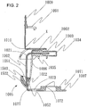
- FIG. 1 is a perspective view of a needle assembly of the present invention showing the post-use state of a needle assembly 1001 when the distal tip end is housed.
- FIG. 2 is a vertical cross-sectional view of the needle assembly of the present invention in the state of FIG. 1 .
- the needle assembly 1001 includes a needle 1002 having a bend portion 1021 of approximately 90° bend, and a hub 1003 for holding a proximal end portion of the needle 1002.
- the needle assembly 1001 includes a distal end guarding portion 1005 for guarding the distal end of the needle 1002, a restraining portion 1006 constituted as a leg portion provided between the distal end guarding portion 1005 and the hub 1003, and a fixing portion 1007 that fixes to the skin and the like of a living body.
- a cover member 1008 is provided in such a way as to cover the hub 1003 in which the needle 1002 is provided.
- a handle portion 1009 is provided in the upper portion of the cover member 1008 by way of a joining portion 1010 which functions as a joint. While in FIG.
- the handle portion 1009 is provided in the needle assembly in such a way as to link with the hub 1003 of the needle 1002 having a bend portion 1021 of approximately 90° bend, a handle portion can be provided in a hub for a common needle in which there is no bend portion.
- the provision of the aforementioned handle portion in the hub allows the hub to be lifted up by the handle portion when the aforementioned needle assembly is converted from the insertion state to the withdrawn state.
- the needle can be easily withdrawn from the living body or the like as a result of the hub being lifted upward.
- the aforementioned fixing portion 1007 is linked with the distal end guarding portion 1005 by way of a hinge portion 1077.
- the aforementioned needle 1002 is mounted in the hub 1003 in such a way as to lie substantially horizontally to the plane in which the living body is deployed, and the needle tip bends downward. While a Huber needle of a shape in which the cutting face is perpendicular to the direction of insertion of the needle is employed as the needle 1002 of the embodiment of FIG. 2 , other surgical needles may also be employed. While the aforementioned bend of the bend portion in FIG. 2 is approximately 90°, there are no particular restrictions to the bend being approximately 90°.
- the needle is able to be inserted into the living body by an operation involving merely a grip portion 1081 at both side faces of the hub 1003 being held between the fingers and pressed from above and, moreover, the needle tube is provided to extend in a direction horizontal to the deployment plane and, as a result, the arrangement of the needle tube is also simple, the bend of the bend portion is preferably approximately 90°.
- a needle distal end portion 1022 of the needle 1002 is housed in the post-use state in the interior of the distal end guarding portion 1005 as shown in FIG. 2 .
- the restraining portion 1006 prevents movement of the distal end guarding portion 5 toward the distal end from the state in which the needle tip is housed.
- the distal end guarding portion 1005 has a needle tip surrounding structure as shown in FIG. 2 constituted from an interior member 1503 and an exterior member 1502.
- the distal end guarding portion 5 encloses the needle distal end portion 1022 and because the positional relationship between the distal end guarding portion 1005 and the needle distal end portion 1022 is restricted by the restraining portion 1006, projection of the needle distal end portion 1022 beyond the needle tip surrounding structure to the exterior of the distal end guarding portion 1005 can be prevented.
- the needle distal end portion 1022 of the needle 1002 is housed in the interior of the distal end guarding portion 1005 due to the flexibility of the needle and/or the needle-contacting section of the distal end guarding portion.
- a tube (not shown in the figure) is connected to be inserted with a tube-connecting hole 1034 of the hub 1003 to afford communication between the cavity of the needle 1002 and the tube cavity.
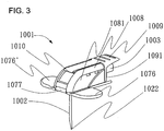
- FIG. 3 is a perspective view of the embodiment of FIG. 1 showing a pre-use state of the needle assembly 1001 of the present invention
- FIG. 4 is a vertical cross-sectional view of the needle assembly 1001 of the present invention of the state of FIG. 3 .
- the pre-use state of the needle assembly 1001 in which, as shown in FIG. 3 , the restraining portion 1006 is provided in a folded state, a state in which the hub 1003 and the fixing portion 1007 are connected by an engaging portion 1032 of the hub 1003 and a connecting portion 1071 of the fixing portion 1007 is established.
- FIG. 3 is a perspective view of the embodiment of FIG. 1 showing a pre-use state of the needle assembly 1001 of the present invention
- FIG. 4 is a vertical cross-sectional view of the needle assembly 1001 of the present invention of the state of FIG. 3 .
- the fixing portion 1007 includes a latching portion 1072 that latches to a connecting portion 1071, and the hub 1003 and the fixing portion 1007 are connected by the engagement of an engaging protrusion 1035 of the engaging portion 1032 with the latching portion 1072.
- the needle 1002 in FIG. 3 is shown in a state in which it passes through a first aperture portion 1051 of the distal end guarding portion 1005 along the distal end guarding portion 1005 and, passing out of a second aperture portion 1052, it further passes through a needle passage 1073 of the fixing portion 1007 to project from the fixing portion 1007.
- a hook portion 1092 of a clasp 1091 provided in the handle portion 1009 is engaged to be inserted in a hole 1075 of a clasp-accepting portion 1074 provided in a fixing portion 1007.
- a state in which the handle portion 1009 is mounted in the cover member as shown in FIG. 3 is established.
- the front-end portion of the handle portion 1009 is lifted up to release the engagement thereof and establish the lifted-up state as shown in FIG. 1 .
- the base end of the handle portion 1009 is attached to the cover member 1008 by way of the coupling portion 1010 to link with the hub 1003.
- the hub 1003 and needle 1002 are lifted up and the needle 1002 is withdrawn from the living body or the like into which it is inserted.
- the base end X of the handle portion preferably lies approximately directly above the vertical portion of the needle 1002.
- the provision of the base end of the handle portion approximately directly above the vertical portion of the needle 1002 ensures that a pull-up force can be applied to the main body portion, which fixes the needle while covering the needle distal end portion with the base end of the handle portion serving as the origin, and ensures the needle 1002 can be lifted up without being caused to oscillate in either the distal end or proximal end directions.
- the provision thereof slightly above and to the distal end side in the horizontal direction from the vertical portion of the needle 1002 is more preferable from the standpoint of ease of housing the needle distal end portion in the distal end guarding portion.
- the handle portion may be directly provided in the main body portion or needle portion in such a way as to link with the needle hub.
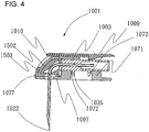
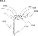
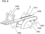
- the needle hub includes a pair of engaging protrusions in its lower side as shown in FIG. 5 , and pairs of convex portions 1036 and 1036' are respectively provided in both side faces thereof. Pairs of holes 1082 and 1082' are provided respectively in both side faces of the cover member attached in such a way as to cover the needle hub as shown in FIG. 6 and, when the cover member is attached to the needle hub, the aforementioned convex portions fit into the aforementioned holes.
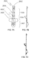
- connection body 2001 in which the fixing portion, the distal end guarding portion and restraining portion are connected is formed as shown in FIG. 7 , and a planar attachment portion 2002, in which a pair of protrusions 2021 is provided, is provided in the other end of the end portion of the restraining portion in which the distal end guarding portion is provided.
- the protrusions 2021 provided in the aforementioned attachment portion 2002 are provided at a width the same as the width between the convex portions 1036 and 1036' provided in one side face of the hub and, accordingly, in a state in which the aforementioned needle has passed along the first aperture portion and the second aperture portion of the distal end guarding portion, the aforementioned attachment portion is fitted to the upper side of the needle hub in such a way that the pair of aforementioned protrusions fit between the respective aforementioned convex portions. Furthermore, the attachment of the cover member to the needle hub from above the aforementioned attachment portion ensures ease of assembly of the needle assembly of the present invention. Furthermore, in the embodiment of FIG.
- connection body 2001 in which a fixing portion, distal end guarding portion and restraining portion are connectively and integrally provided is employed, the employment of a connection body in which these elements are integrated is not a requisite constituent element of the present invention for needle tip guarding.
- FIG. 7 for example for a connection body in which hinge portions are respectively provided between each of the fixing portions, the distal end guarding portion, the restraining portion and the attachment portion in that sequence, arbitrary angles can be adopted between mutually adjacent sections thereof and, accordingly, the assembly of the needle assembly is simple and, moreover, this is further desirable in that transformation from the pre-use state to the post-use state thereof can be smoothly implemented, thereby simplifying the needle tip guarding.
- the coupling may be accomplished by adhesion instead of fitting.
- the distal end guarding portion of the embodiment of FIG. 1 is constituted from two members and includes an exterior member 1502 and interior member 1503.
- the interior member 1503 includes a side-aperture portion 1531 in one side face.
- an interior member having a needle tip surrounding structure may be employed.
- the side-aperture portion 1531 includes a second aperture end 1533 at the boundary between a right-side face 1534 and base face, and a first aperture end 1532 at the boundary between the right-side face 1534 and rear face 1535. As shown in FIG.
- the shape of the side-aperture portion 1531 corresponds to the bend portion of the needle 1002, which defines a shape in which the section of the needle 1002 extending in the vertical direction passes through the second aperture end 1533 and the section of the needle 1002 extending in the horizontal direction passes through the first aperture end 1532 so that the bend portion, passing through the side-aperture portion, is housed in the interior of the interior member.
- needle and needle hub is established by attachment of an attachment portion to the upper portion of the aforementioned needle hub and the engaging protrusions of the needle hub being caused to engage with the engagement-receiving portions and, as a result of the aforementioned interior member being fitted through the side face of the aforementioned exterior member and being covered from above by a cover member, damage to the needle tip can be prevented and, moreover, the needle assembly can be easily assembled.
- the restraining portion of the embodiment of FIG. 1 is identical to the restraining portion of the first embodiment and, provided the restraining portion is satisfactorily able to demonstrate a function of restricting the distance between the distal end guarding portion and the hub and is able to inhibit re-protrusion of the needle tip from the distal end guarding portion to the exterior, there are no particular limitations thereto. Furthermore, while the restraining portion able to demonstrate this function of the present invention described above is shown as a pair of leg portions, the restraining portion may describe a ladder-like shape or a plate shape.
Landscapes
- Health & Medical Sciences (AREA)
- Vascular Medicine (AREA)
- Engineering & Computer Science (AREA)
- Anesthesiology (AREA)
- Biomedical Technology (AREA)
- Heart & Thoracic Surgery (AREA)
- Hematology (AREA)
- Life Sciences & Earth Sciences (AREA)
- Animal Behavior & Ethology (AREA)
- General Health & Medical Sciences (AREA)
- Public Health (AREA)
- Veterinary Medicine (AREA)
- Infusion, Injection, And Reservoir Apparatuses (AREA)
Description
- The present invention relates to a safety needle assembly for guarding a needle tip, and particularly to a safety needle assembly in which a needle having a bend portion is employed, and more particularly to a Huber needle assembly serving as an insertion needle for use in a subcutaneous implant-type catheter access port. The present invention relates even more particularly to a Huber needle assembly including a safety mechanism for preventing accidental needlestick designed in such a way as to ensure the distal end of the needle of a Huber needle assembly inserted in a catheter access port is covered when it is withdrawn therefrom.
- A surgical needle normally employed as the needle for, for example, insertion in a subcutaneous implant-type catheter access port is not a common injection needle, but rather a Huber needle of a shape in which the cutting surface is perpendicular to the direction of insertion in such a way as to prevent coring when the septum of the port is punctured. Huber needles that have a bend portion of 90° and to which wings parallel in the horizontal direction are fixed thereto are employed for uses including continuous infusion.
- Inadvertent needle stick of the medical staff or the patient following use is a problem commonly associated with needle assemblies including Huber needle assemblies that have wings provided in parallel in the horizontal direction such as this. In addition, it is recognized that merely scratching the skin with an unprotected sharp tip of a used needle may be sufficient to cause transmission of an infectious disease. In the USA, where the "Needlestick Safety and Prevention Act" has been enacted, the use of a safety-type needle assembly and more particularly a safety Huber needle assembly is needed.
- As an example of a safety-type needle assembly having a bend portion for resolving the problem described above, a folding wing-type needle assembly including an approximately 90° bend portion and in which flat wings are able to be moved to a guarded position, where contact with the distal end of the needle is prevented, has been disclosed (see Patent Document 1).
- Patent Document 1: Published
Japanese Patent Application No. 2004-510555 - In the aforementioned safety-type needle assembly, contact of the needle with the fingertips is rendered unlikely as a result of the wings being simply folded down around the needle and, as a result, inadvertent needle stick can be prevented. Accordingly, inadvertent needle stick can be prevented by a simple operation using the aforementioned needle assembly.
- However, in the aforementioned needle assembly, in order for the wings to guard the needle tip simultaneously with the needle being withdrawn from the living body, the wings must be of a sufficient weight to ensure falling under their own weight and, accordingly, when the needle assembly is deployed, the wings press against the patient and cause increased patient discomfort. Moreover, when the aforementioned needle assembly is deployed in the arm or chest regions of a patient, expansion of the wings to lie perpendicular to the direction of gravity is prevented, which in turn renders it difficult for the wings to guard the needle tip simultaneously with the needle being withdrawn from the living body. In addition, since the return of the wings in the aforementioned needle assembly is prevented by the provision of a shallow stepped stopper portion and, accordingly, contact between the needle and the body is prevented so long as only a light force is applied thereto, prevention of needle exposure becomes difficult with a strong external force on the wings.
Furthermore, the aforementioned needle assembly does not constitute a structure in which the area of the distal end of the needle in the section thereof that comes into contact with the living body is covered. For this reason, there is potential for the bodily fluids adhered to the needle to splash or come into contact with the body and, in turn, there is potential for infectious diseases such as HIV or hepatitis to be transmitted by the contact or splash of these bodily fluids. - Document
US 2005/0049553 discloses a needle assembly according to the preamble of claim 1. - It is an object of the present invention to prevent needlestick injuries by providing a safety needle assembly for guarding a needle tip, by further providing a safety-type needle assembly having a bend portion and to which an inadvertent needlestick prevention mechanism is fitted, and more particularly by providing a safety-type Huber needle assembly.
- That is, the present invention constitutes a needle assembly as defined in claim 1.
- In addition, as the aforementioned needle, a Huber needle may be employed.
- Furthermore, a needle tip guarding mechanism may include: a needle in which a cutting blade is formed in a distal end; a hub for holding a proximal end portion of the needle; and a distal end guarding portion, in which the needle tip guarding mechanism includes a restraining portion for restricting a distance between the needle and the hub, the distal end guarding portion includes a mechanism for flexing the needle tip, and the distal end of the needle is guarded by, when the distal end guarding portion is moved to a position to guard the distal end of the needle, flexure of the needle tip by the aforementioned mechanism to house the needle tip in an interior of the distal end guarding portion
- The present invention of the needle assembly as described above can be effectively used as a safety needle assembly irrespective of whether the needle has a bend portion or not and, more particularly, it can be effectively used as a subcutaneous implant-type catheter access port insertion needle that has a bend portion and, furthermore, it is ideal for employment in medical treatment methods that involve the use of a catheter. In addition, as the cutting blade is not caused to reprotrude when an external force is applied to the needle tip in the guarded state, the safety needle assembly of the present invention offers a high degree of safety and, as it can be employed in such a way that the cutting blade is guarded simultaneously with the needle being removed from a living body, the present invention offers an improved degree of safety. In addition, as the needle assembly of the present invention describes a structure in which blood and bodily fluids adhering to the needle tip can be prevented from coming into contact with the body, it constitutes an ideal needle assembly for preventing secondary medical injuries.
-
-
FIG. 1 is a perspective view of the post-use state of an embodiment of the needle assembly of the present invention; -
FIG. 2 is a cross-sectional view of the post-use state of an embodiment of the needle assembly of the present invention; -
FIG. 3 is a perspective view of the pre-use state of the needle assembly ofFIG. 1 ; -
FIG. 4 is a cross-sectional view of the pre-use state of the needle assembly ofFIG. 1 ; -
FIG. 5 is a perspective view of the needle and hub of the needle assembly ofFIG. 1 ; -
FIG. 6 is a perspective view of the cover member of the needle assembly ofFIG. 1 ; -
FIG. 7 A is a front view of the connection body of the needle assembly ofFIG. 1 , B is a left-side view of the connection body of A, and C is a vertical cross-sectional view of the connection body of A; -
FIG. 8 A is a perspective view from the rear of the distal end guarding member of the needle assembly ofFIG. 1 , B is a right-side view of the distal end guarding member of A, C is a vertical cross-sectional view of the distal end guarding member of A, and D is a base view of the distal end guarding member of A. - The needle assembly of the present invention shall be hereinafter described in detail with reference to the figures. The following passages not referring to the figures do not describe embodiments of the present invention.
- According to a first embodiment, a needle assembly includes a needle having a bend portion of an approximately 90° bend, and a hub for holding the proximal end portion of the needle.
- The needle assembly includes a distal end guarding portion for guarding the distal end of the needle, a restraining portion provided between the distal end guarding portion and the hub, and a fixing portion that fixes to the skin or the like of a living body. The aforementioned fixing portion links with the distal end guarding portion. The aforementioned needle is mounted in the hub provided essentially horizontal to the plane of deployment of the living body, and the needle tip bends downward. While a Huber needle of a shape in which the cutting face is perpendicular to the direction of insertion of the needle is employed as the needle of the embodiment, other surgical needles may also be employed. While the aforementioned bend of the bend portion is approximately 90°, there are no particular restrictions to the bend being approximately 90°. However, as the needle is able to be inserted in the living body by an operation involving merely a grip portion being held between the fingers and pressed from above and, moreover, the needle tube is provided to extend in a direction horizontal to the deployment plane, whereby the arrangement of the tube is also simple, the bend of the bend portion is preferably approximately 90°.
- Following usage, a needle distal end portion of the needle of the embodiment is housed in the interior of the distal end guarding portion. The distal end guarding portion is designed so that, when the needle distal end portion is housed in the interior of the distal end guarding portion, the distance thereof to the hub is restricted by the restraining portion so that, accordingly, movement toward the distal end from the state in which the needle tip is housed is prevented. In addition, the distal end guarding portion describes a needle tip surrounding structure and encloses the needle distal end portion of the needle with play and, because the positional relationship between the distal end guarding portion and the needle distal end portion is restricted by the restraining portion, projection of the needle beyond the needle tip surrounding structure to the exterior of the distal end guarding portion can be prevented. Furthermore, when a state in which the needle distal end portion is enclosed within the interior of the distal end guarding portion with play is established, the exterior of the distal end guarding portion and the needle distal end portion are in contact as described later, and the needle distal end portion is housed in the interior of the distal end guarding portion due to the flexibility of the needle and/or the needle-contacting section of the distal end guarding portion. Moreover, a tube connects to a tube-connecting hole of the hub to impart communication between the cavity of the needle and the tube cavity.
- The pre-use state to the post-use state in which the needle distal end portion of the needle is guarded of the embodiment is shown in the diagrams. In the pre-use state of the needle assembly, the restraining portion is folded, and the hub and the fixing portion are provided in a state in which an engaging portion of the hub and a connecting portion of the fixing portion are connected. An engagement-receiving portion configured as an opening is provided in the connecting portion and, as a result of the engagement thereof with an engaging protrusion of the engaging portion, the hub and the fixing portion are connected. The needle is provided in a state in which it passes through a first aperture portion of the distal end guarding portion to pass along the distal end guarding portion and, passing out of a second aperture portion, it passes further along a needle passage of the fixing portion to project from the fixing portion. While in the pre-use state of the needle assembly, wing portions may be held to insert the needle into living body, instead of wing portions, a grip portion may be provided, and this grip portion held as the needle is inserted into the living body.
- In the post-use state, the needle assembly lies in an intermediate state in which the hub and the fixing portion are separated. In a state in which the needle has penetrated the first aperture portion located in the needle proximal end-side and the second aperture portion located in the needle distal end-side and furthermore, in which it has penetrated the needle portion , the distal end guarding portion and the fixing portion are moved relatively in the needle distal end direction. Hinge portions are provided in the restraining portion of the needle assembly and, in addition, a hinge portion is provided between the distal end guarding portion and the fixing portion. Provided the restraining portion can be converted from the folded state to the extended state, there are no particular restrictions to the provision of the hinge portions or to the number thereof, and a restraining portion having a slidable extending member, or hinge portions of a wedge-shaped structure or hinge portions rotationally movable about a hinge including a rotary pin may be employed, or bendable members including linear members such as a strap member may also be employed. The hinge portions of the restraining portion allow it to be compactly, foldably-housed and, moreover, because the restraining portion can be formed from a material that does not elongate in the length direction, the restraining portion can satisfactorily demonstrate the function of restricting the distance between the distal end guarding portion and the hub with little change in the length direction. In addition, the needle assembly includes two restraining portions between a hub front face and the distal end guarding portion. While there are no particular restrictions to the number of restraining portions, where a structure for stably connecting the hub and the fixing portion including two engaging portions interposed at both sides of the connecting portion is to be adopted, as they can be arranged in a space-saving state in both sides of the connecting portion, it is preferable for two restraining portions to be provided.
- The distal end guarding portion and fixing portion are relatively moved in the needle tip direction from the state of the needle assembly, the fixing portion moves beyond the needle distal end to separate from the needle, and the needle tip is housed in the interior of the distal end guarding portion. The needle is housed in the distal end guarding portion at this time due to the elasticity of the needle. The mechanism described below for housing a needle tip in a distal end guarding portion has been considered. As the positional relationship between the distal end guarding portion and the needle tip is being restricted by the restraining portion, a state in which the needle is in contact with the interior of a fulcrum portion of the distal end guarding portion and the exterior of a needle tip retraction preventing portion is established. Furthermore, when the distal end guarding portion is caused to move relatively due to the application of a force M in the distal end direction of the needle, the needle tip is subject to a force N in the relative rotational direction about the fulcrum portion. Due to the elasticity thereof, the portion of the needle in proximity of the needle tip is flexed to the interior of the distal end guarding portion. As a result of this flexure, a length component L of the needle contracts in the distal end direction, the distal end guarding portion moves relatively beyond the needle tip to the distal end-side, and the needle tip is housed in the interior of the distal end guarding portion. The needle tip retraction preventing portion extends in the length direction of the needle and, as a result, it holds the needle tip in the interior of the distal end guarding portion and, because the distal end guarding portion does not include a structure in its interior for flexing the needle, the needle tip does not protrude to the exterior.
- An end portion of the restraining portion links with the distal end guarding portion and, while there are no particular restrictions to this linking section, the section where the restraining portion links with the distal end guarding portion in a vertical direction V to the length direction of the needle is preferably one of the same position as the fulcrum portion or the distal end guarding position on the opposing side of the needle with respect to the fulcrum portion. Furthermore, when the needle tip is to be guarded by the aforementioned distal end guarding portion, while the distal end guarding portion can be held by the hand and caused to move in the needle distal end direction, when a fixing portion connected to the distal end guarding portion is provided, the needle distal end can be easily guarded, while pressing the fixing portion in the ground plane direction, by lifting the needle hub upward.
- The distal end guarding portion of a needle assembly may constitute a structure in which the fulcrum portion and the needle tip retraction preventing member constitute the same member, and may constitute a structure in which the interior member including the fulcrum portion and the needle tip retraction preventing member are inlaid into the interior of an exterior member from which the exterior of the distal end guarding portion is constituted. In addition, a structure in which an interior member including a fulcrum portion and a needle tip retraction preventing member is provided in the interior of an exterior member including a slit from which the exterior of the distal end guarding portion is constituted may also be adopted. If a structure such as this is adopted, subsequent to a needle shaft being arranged through the slit into the interior of the distal end guarding portion as shown in the state of, for example, an interior member can be inserted from the lateral direction into an exterior member to establish a state in which the distal end of the needle can be guarded by the distal end guarding portion. By the adoption of a structure such as this in which a slit is provided in the distal end guarding portion and in which, with the distal end guarding portion constituted from two members, an interior member including the fulcrum portion and needle tip retraction preventing portion is inlaid into an exterior member in a state in which the shaft of the needle is arranged in a position to penetrate the distal end tip guarding portion material, there is no need in the needle assembly for the distal end guarding portion material to be penetrated once the needle and hub have been joined and, accordingly, the operation for joining the needle and the hub is simplified, and the manufacturability thereof is superior.
- In the following a needle assembly according to the invention is explained with reference to the drawings.
FIG. 1 is a perspective view of a needle assembly of the present invention showing the post-use state of aneedle assembly 1001 when the distal tip end is housed.FIG. 2 is a vertical cross-sectional view of the needle assembly of the present invention in the state ofFIG. 1 . As shown inFIG. 2 , theneedle assembly 1001 includes aneedle 1002 having abend portion 1021 of approximately 90° bend, and ahub 1003 for holding a proximal end portion of theneedle 1002. Theneedle assembly 1001 includes a distalend guarding portion 1005 for guarding the distal end of theneedle 1002, a restrainingportion 1006 constituted as a leg portion provided between the distalend guarding portion 1005 and thehub 1003, and a fixingportion 1007 that fixes to the skin and the like of a living body. In theneedle assembly 1001, acover member 1008 is provided in such a way as to cover thehub 1003 in which theneedle 1002 is provided. Ahandle portion 1009 is provided in the upper portion of thecover member 1008 by way of a joiningportion 1010 which functions as a joint. While inFIG. 1 thehandle portion 1009 is provided in the needle assembly in such a way as to link with thehub 1003 of theneedle 1002 having abend portion 1021 of approximately 90° bend, a handle portion can be provided in a hub for a common needle in which there is no bend portion. The provision of the aforementioned handle portion in the hub allows the hub to be lifted up by the handle portion when the aforementioned needle assembly is converted from the insertion state to the withdrawn state. The needle can be easily withdrawn from the living body or the like as a result of the hub being lifted upward. - The
aforementioned fixing portion 1007 is linked with the distalend guarding portion 1005 by way of ahinge portion 1077. Theaforementioned needle 1002 is mounted in thehub 1003 in such a way as to lie substantially horizontally to the plane in which the living body is deployed, and the needle tip bends downward. While a Huber needle of a shape in which the cutting face is perpendicular to the direction of insertion of the needle is employed as theneedle 1002 of the embodiment ofFIG. 2 , other surgical needles may also be employed. While the aforementioned bend of the bend portion inFIG. 2 is approximately 90°, there are no particular restrictions to the bend being approximately 90°. However, since the needle is able to be inserted into the living body by an operation involving merely agrip portion 1081 at both side faces of thehub 1003 being held between the fingers and pressed from above and, moreover, the needle tube is provided to extend in a direction horizontal to the deployment plane and, as a result, the arrangement of the needle tube is also simple, the bend of the bend portion is preferably approximately 90°. - In the embodiment of
FIG. 1 , a needledistal end portion 1022 of theneedle 1002 is housed in the post-use state in the interior of the distalend guarding portion 1005 as shown inFIG. 2 . Similarly to the first embodiment, the restrainingportion 1006 prevents movement of the distal end guarding portion 5 toward the distal end from the state in which the needle tip is housed. In addition, the distalend guarding portion 1005 has a needle tip surrounding structure as shown inFIG. 2 constituted from aninterior member 1503 and anexterior member 1502. Since the distal end guarding portion 5 encloses the needledistal end portion 1022 and because the positional relationship between the distalend guarding portion 1005 and the needledistal end portion 1022 is restricted by the restrainingportion 1006, projection of the needledistal end portion 1022 beyond the needle tip surrounding structure to the exterior of the distalend guarding portion 1005 can be prevented. Furthermore, similarly to the first embodiment, the needledistal end portion 1022 of theneedle 1002 is housed in the interior of the distalend guarding portion 1005 due to the flexibility of the needle and/or the needle-contacting section of the distal end guarding portion. Moreover, a tube (not shown in the figure) is connected to be inserted with a tube-connectinghole 1034 of thehub 1003 to afford communication between the cavity of theneedle 1002 and the tube cavity. -
FIG. 3 is a perspective view of the embodiment ofFIG. 1 showing a pre-use state of theneedle assembly 1001 of the present invention, andFIG. 4 is a vertical cross-sectional view of theneedle assembly 1001 of the present invention of the state ofFIG. 3 . In the pre-use state of theneedle assembly 1001 in which, as shown inFIG. 3 , the restrainingportion 1006 is provided in a folded state, a state in which thehub 1003 and the fixingportion 1007 are connected by an engaging portion 1032 of thehub 1003 and a connectingportion 1071 of the fixingportion 1007 is established. As shown inFIG. 1 , the fixingportion 1007 includes a latchingportion 1072 that latches to a connectingportion 1071, and thehub 1003 and the fixingportion 1007 are connected by the engagement of an engagingprotrusion 1035 of the engaging portion 1032 with the latchingportion 1072. - In addition, the
needle 1002 inFIG. 3 is shown in a state in which it passes through afirst aperture portion 1051 of the distalend guarding portion 1005 along the distalend guarding portion 1005 and, passing out of asecond aperture portion 1052, it further passes through aneedle passage 1073 of the fixingportion 1007 to project from the fixingportion 1007. In this pre-use state and when, for example, a medical solution is to be injected employing theneedle assembly 1001, thegrip portion 1081 in both sides of thecover member 1008 of theneedle assembly 1001 is held between the fingers to insert theneedle 1002 into the living body whereupon, by way of a tube (not shown in the figure) connected to thetube connecting hole 1034 and the cavity of theneedle 1002, the medical solution can be injected into the living body or the like. Furthermore, conversion from the pre-use state of theneedle assembly 1001 ofFIG. 3 andFIG. 4 to the post-use state ofFIG. 1 andFIG. 2 when the needle distal end is guarded can be implemented as follows. For theneedle assembly 1001 in the state ofFIG. 3 in which theneedle 1002 is inserted into a living body or a port, by pressingwing portions 1076 and 1076' of the fixingportion 1007 deployed on the surface of the living body downward using the fingers of one hand while holding thegrip portion 1081 in the fingers of the other hand and lifting up, the engagement between the fixingportion 1007 and thehub 1003 is released to afford the separation thereof and the establishment of the post-use state ofFIG. 1 andFIG. 2 (state in which the needle tip is guarded). Furthermore, a protrusion to facilitate fixing using the fingers or for use as a slip guard may be provided in thegrip portion 1081. In addition, as a different method of insertion, a method based on the wing portions being bent and the insertion being performed while holding a grip portion by way of these wing portions is also possible. - In the usage state of
FIG. 3 andFIG. 4 of theneedle assembly 1001, ahook portion 1092 of aclasp 1091 provided in thehandle portion 1009 is engaged to be inserted in ahole 1075 of a clasp-acceptingportion 1074 provided in a fixingportion 1007. As a result of this engagement, a state in which thehandle portion 1009 is mounted in the cover member as shown inFIG. 3 is established. In the post-use state when the insertedneedle assembly 1001 is withdrawn from the living body or the like, the front-end portion of thehandle portion 1009 is lifted up to release the engagement thereof and establish the lifted-up state as shown inFIG. 1 . The base end of thehandle portion 1009 is attached to thecover member 1008 by way of thecoupling portion 1010 to link with thehub 1003. By pressingwing portions 1076 and 1076' downward by the fingers of one hand and lifting up thehandle portion 1009 held with the other hand in the vertical direction as shown inFIG. 1 andFIG. 2 , thehub 1003 andneedle 1002 are lifted up and theneedle 1002 is withdrawn from the living body or the like into which it is inserted. When theneedle 1002 is withdrawn, the base end X of the handle portion preferably lies approximately directly above the vertical portion of theneedle 1002. The provision of the base end of the handle portion approximately directly above the vertical portion of theneedle 1002 ensures that a pull-up force can be applied to the main body portion, which fixes the needle while covering the needle distal end portion with the base end of the handle portion serving as the origin, and ensures theneedle 1002 can be lifted up without being caused to oscillate in either the distal end or proximal end directions. The provision thereof slightly above and to the distal end side in the horizontal direction from the vertical portion of theneedle 1002 is more preferable from the standpoint of ease of housing the needle distal end portion in the distal end guarding portion. Furthermore, while in this embodiment the main body portion for supporting the needle is constituted from the needle hub and the cover member and the handle portion is coupled to the upper portion of the cover member, the handle portion may be directly provided in the main body portion or needle portion in such a way as to link with the needle hub. - While there are no particular limitations to the configuration of the embodiment of
FIG. 1 , as an example thereof, the following configuration may be adopted. The needle hub includes a pair of engaging protrusions in its lower side as shown inFIG. 5 , and pairs ofconvex portions 1036 and 1036' are respectively provided in both side faces thereof. Pairs ofholes 1082 and 1082' are provided respectively in both side faces of the cover member attached in such a way as to cover the needle hub as shown inFIG. 6 and, when the cover member is attached to the needle hub, the aforementioned convex portions fit into the aforementioned holes. In addition, for the fixing portion, distal end guarding portion and restraining portion, aconnection body 2001 in which the fixing portion, the distal end guarding portion and restraining portion are connected is formed as shown inFIG. 7 , and aplanar attachment portion 2002, in which a pair ofprotrusions 2021 is provided, is provided in the other end of the end portion of the restraining portion in which the distal end guarding portion is provided. Theprotrusions 2021 provided in theaforementioned attachment portion 2002 are provided at a width the same as the width between theconvex portions 1036 and 1036' provided in one side face of the hub and, accordingly, in a state in which the aforementioned needle has passed along the first aperture portion and the second aperture portion of the distal end guarding portion, the aforementioned attachment portion is fitted to the upper side of the needle hub in such a way that the pair of aforementioned protrusions fit between the respective aforementioned convex portions. Furthermore, the attachment of the cover member to the needle hub from above the aforementioned attachment portion ensures ease of assembly of the needle assembly of the present invention. Furthermore, in the embodiment ofFIG. 1 , while aconnection body 2001 in which a fixing portion, distal end guarding portion and restraining portion are connectively and integrally provided is employed, the employment of a connection body in which these elements are integrated is not a requisite constituent element of the present invention for needle tip guarding. However, as shown inFIG. 7 for example, for a connection body in which hinge portions are respectively provided between each of the fixing portions, the distal end guarding portion, the restraining portion and the attachment portion in that sequence, arbitrary angles can be adopted between mutually adjacent sections thereof and, accordingly, the assembly of the needle assembly is simple and, moreover, this is further desirable in that transformation from the pre-use state to the post-use state thereof can be smoothly implemented, thereby simplifying the needle tip guarding. Furthermore, the coupling may be accomplished by adhesion instead of fitting. - The distal end guarding portion of the embodiment of
FIG. 1 is constituted from two members and includes anexterior member 1502 andinterior member 1503. Theinterior member 1503 includes a side-aperture portion 1531 in one side face. Similarly to the first embodiment, an interior member having a needle tip surrounding structure may be employed. The side-aperture portion 1531 includes asecond aperture end 1533 at the boundary between a right-side face 1534 and base face, and afirst aperture end 1532 at the boundary between the right-side face 1534 andrear face 1535. As shown inFIG. 8 , the shape of the side-aperture portion 1531 corresponds to the bend portion of theneedle 1002, which defines a shape in which the section of theneedle 1002 extending in the vertical direction passes through thesecond aperture end 1533 and the section of theneedle 1002 extending in the horizontal direction passes through thefirst aperture end 1532 so that the bend portion, passing through the side-aperture portion, is housed in the interior of the interior member. By the adoption of a distal end guarding portion of an interior member of a shape such as this as the aforementioned distal end guarding portion, a pre-use state as shown inFIG. 3 of a connection body, needle and needle hub is established by attachment of an attachment portion to the upper portion of the aforementioned needle hub and the engaging protrusions of the needle hub being caused to engage with the engagement-receiving portions and, as a result of the aforementioned interior member being fitted through the side face of the aforementioned exterior member and being covered from above by a cover member, damage to the needle tip can be prevented and, moreover, the needle assembly can be easily assembled. - The restraining portion of the embodiment of
FIG. 1 is identical to the restraining portion of the first embodiment and, provided the restraining portion is satisfactorily able to demonstrate a function of restricting the distance between the distal end guarding portion and the hub and is able to inhibit re-protrusion of the needle tip from the distal end guarding portion to the exterior, there are no particular limitations thereto. Furthermore, while the restraining portion able to demonstrate this function of the present invention described above is shown as a pair of leg portions, the restraining portion may describe a ladder-like shape or a plate shape.
Claims (12)
- A needle assembly (1001) comprising a needle (1002) having a cutting blade formed in a distal end (1022), a hub (1003) for holding a proximal end portion of the needle (1002), and a distal end guarding portion (1005), the distal end guarding portion (1005) having a mechanism for flexing the needle tip, wherein the distal end of the needle is guarded, when the distal end guarding portion (1005) is moved to a position to guard the distal end of the needle, by the needle tip being flexed by the mechanism to house the needle tip in the interior of the distal end guarding portion, the needle assembly (1001) comprising:a restraining portion (1006) for restricting a distance between the distal end guarding portion (1005) and the hub (1003); and,a fixing portion (1007) connected to the distal end guarding portion (1005),wherein the distal end guarding portion (1005) has a first aperture portion (1051) arranged at a proximal end of the needle (1002), a second aperture portion (1052) arranged at a distal end of the needle (1002), and a needle tip retraction preventing portion arranged at the second aperture portion (1052); and,wherein the needle (1002), in a pre-usage stage, is inserted into the distal end guarding portion (1005) from the first aperture portion (1051) of the distal end guarding portion (1005) to project from the second aperture portion (1052), andafter usage, moves from the second aperture portion (1052) by the needle (1002), which is in contact with the needle tip retraction preventing portion, flexing,and the distal end of the needle (1002) is guarded by the needle tip being housed inside the distal end guarding portion (1005) in a state of being engaged with the distal end guarding portion (1005),the needle assembly being characterized in that an opening of the first aperture portion (1051) and an opening of the second aperture portion (1052) form an approximate right angle with respect to each other, and in that the distal end guarding portion (1005) is connected to the fixing portion (1007) via a hinge portion, the distal end guarding portion (1005) rotating via the hinge portion (1077) with respect to the fixing portion (1007).
- The needle assembly (1001) according to claim 1, wherein the needle (1002), which is in contact with the needle tip retraction preventing portion, flexes with the first aperture portion (1051) as a support point.
- The needle assembly (1001) according to any of claims 1 or 2, wherein the needle (1002) has a bend portion (1021).
- The needle assembly (1001) according to any of claims 1 to 3, wherein the fixing portion has a needle passage (1073) through which the needle (1002) is able to move in an axial direction.
- The needle assembly (1001) according to any of claims 1 to 4, wherein the restraining portion (1006) forms a folded structure in the pre-use state.
- The needle assembly (1001) according to any of claims 1 to 5, wherein the needle (1002) is a Huber needle.
- The needle assembly (1001) according to claim 3, wherein a bend of the bend portion (1021) is a substantially 90° bend.
- The needle assembly (1001) according to any of claims 1 to 7, wherein the needle assembly (1001) further comprises a handle portion (1009) that links with the needle hub (1003),
the handle portion (1009) being provided in the needle assembly (1001) in such a way that, as a result of being pulled upward during conversion from an insertion state of the needle assembly (1001) to a withdrawn state of the needle (1002), the hub (1003) is lifted up by way of a coupling portion (1010). - The needle assembly (1001) according to claim 8, wherein the handle portion (1009) has a clasp (1091) by which the handle portion engages with the fixing portion (1007),the handle portion (1009) being provided to be turnable so that a front-end portion thereof describes an arc a center thereof is the coupling portion (1010),and the engagement between the handle portion (1009) and the fixing portion (1007) being released by lifting up an end portion of the handle portion (1009).
- The needle assembly (1001) according to claim 8 or 9 when dependent from claim 3,wherein the handle portion (1009) is linked with the needle hub (1003) by way of the coupling portion (1010),the coupling portion (1010) being provided in a horizontal direction of the needle (1002) in a position substantially directly above a vertical portion from which the distal end-side from the bend portion (1021) of the needle (1002) is constituted.
- The needle assembly (1001) according to claim 10, the needle assembly (1001) comprising a cover member (1008) that in the insertion state covers the distal end guarding portion (1005) and connects with the hub (1003), wherein the handle portion (1009) is provided in the cover member (1008) by way of the coupling portion (1010).
- The needle assembly (1001) according to claim 11, the needle assembly (1001) including a connection body comprising the fixing portion (1007), the distal end guarding portion (1005) and the restraining portion (1006), wherein the connection body further comprises an attachment portion, the attachment portion being fixed to the hub (1003) between the hub (1003) and the cover member (1008).
Applications Claiming Priority (2)
| Application Number | Priority Date | Filing Date | Title |
|---|---|---|---|
| JP2006126889 | 2006-04-28 | ||
| PCT/JP2007/059259 WO2007126085A1 (en) | 2006-04-28 | 2007-04-27 | Safety needle assembly |
Publications (3)
| Publication Number | Publication Date |
|---|---|
| EP2016964A1 EP2016964A1 (en) | 2009-01-21 |
| EP2016964A4 EP2016964A4 (en) | 2014-06-11 |
| EP2016964B1 true EP2016964B1 (en) | 2021-10-06 |
Family
ID=38655605
Family Applications (1)
| Application Number | Title | Priority Date | Filing Date |
|---|---|---|---|
| EP07742694.8A Active EP2016964B1 (en) | 2006-04-28 | 2007-04-27 | Safety needle assembly |
Country Status (8)
| Country | Link |
|---|---|
| US (1) | US8496626B2 (en) |
| EP (1) | EP2016964B1 (en) |
| JP (3) | JP4853516B2 (en) |
| CN (1) | CN101432035B (en) |
| BR (1) | BRPI0710395B8 (en) |
| ES (1) | ES2899444T3 (en) |
| MX (1) | MX2008013742A (en) |
| WO (1) | WO2007126085A1 (en) |
Families Citing this family (35)
| Publication number | Priority date | Publication date | Assignee | Title |
|---|---|---|---|---|
| WO2006096635A1 (en) | 2005-03-07 | 2006-09-14 | Erskine Medical Llc | Catheter introducer with needle shield |
| BRPI0710395B8 (en) * | 2006-04-28 | 2021-06-22 | Nipro Corp | safety needle assembly and needle mechanism |
| EP2355944A1 (en) * | 2008-11-11 | 2011-08-17 | Novo Nordisk A/S | A bended injection needle |
| EP2403559A4 (en) * | 2009-03-05 | 2013-04-03 | Erskine Medical Llc | Needle-based medical device and related method |
| CA2769510C (en) * | 2009-07-31 | 2017-11-21 | Medical Components, Inc. | Huber needle with safety tube |
| JP5538913B2 (en) * | 2010-01-13 | 2014-07-02 | 川澄化学工業株式会社 | Medical needle |
| WO2011123685A2 (en) * | 2010-03-31 | 2011-10-06 | Autosafe Reflex , Inc. | Needle protective device |
| WO2012075421A1 (en) | 2010-12-02 | 2012-06-07 | Erskine Medical Llc | Release mechanism for use with needle shielding devices |
| WO2012075402A1 (en) | 2010-12-02 | 2012-06-07 | Erskine Medical Llc | Needle shield assembly with hub engagement member for needle device |
| MX349414B (en) | 2011-04-07 | 2017-07-20 | Erskine Medical Llc | Needle shielding device. |
| EP2572742A1 (en) * | 2011-09-23 | 2013-03-27 | Sanofi-Aventis Deutschland GmbH | Needle safety device |
| WO2013098986A1 (en) * | 2011-12-28 | 2013-07-04 | 川澄化学工業株式会社 | Medical needle safety device |
| JP2013138853A (en) * | 2011-12-28 | 2013-07-18 | Kawasumi Lab Inc | Medical needle safety device |
| US20130237928A1 (en) * | 2012-03-07 | 2013-09-12 | Medical Components, Inc. | Huber Needle Assembly |
| DE102012102519A1 (en) * | 2012-03-23 | 2013-09-26 | Pfm Medical Ag | Safety pin device, in particular for puncturing a subcutaneously implanted port in a human or animal body |
| CN104619365B (en) * | 2012-09-28 | 2017-04-19 | 泰尔茂株式会社 | Puncture device and medical fluid application device |
| US9119939B2 (en) * | 2013-09-12 | 2015-09-01 | Michael J. Botich | Rotatable hypodermic needle and method of use |
| US20150080856A1 (en) * | 2013-09-18 | 2015-03-19 | David Stroup | Medical infusion device and methods of use |
| US10549028B2 (en) | 2013-09-18 | 2020-02-04 | Alliance Vascular Devices, Llc | Medical infusion device and methods of use |
| US9999723B2 (en) | 2013-10-10 | 2018-06-19 | Medical Components, Inc. | Huber needle assembly with safety capture device |
| USD787665S1 (en) * | 2013-11-28 | 2017-05-23 | Pengfei Wu | Curved hypodermic needle |
| NZ762033A (en) * | 2014-03-28 | 2022-07-01 | Takeda Pharmaceuticals Co | A subcutaneous infusion device for injecting medicinal substances |
| US10058651B1 (en) * | 2014-04-22 | 2018-08-28 | Suntori Medical, LLC | Safety needle device for accessing a medical port |
| JP6730255B2 (en) | 2014-08-29 | 2020-07-29 | メデイカル コンポーネンツ,インコーポレーテツド | Huba safety needle |
| USD804022S1 (en) | 2015-02-27 | 2017-11-28 | Medical Components, Inc. | Huber safety needle |
| USD804021S1 (en) | 2015-02-27 | 2017-11-28 | Medical Components, Inc. | Huber safety needle |
| CN108472438B (en) * | 2015-10-09 | 2022-01-28 | 西医药服务以色列分公司 | Tortuous fluid path attachment to pre-filled fluid reservoirs |
| JP6896753B2 (en) * | 2016-03-18 | 2021-06-30 | メデイカル コンポーネンツ,インコーポレーテツド | Hoover needle assembly |
| JP6941292B2 (en) * | 2017-07-24 | 2021-09-29 | ニプロ株式会社 | Needle assembly |
| CN108066846B (en) * | 2017-12-28 | 2021-02-12 | 罗亚琴 | Needle head protection device and needle head protection equipment |
| WO2019213097A1 (en) | 2018-05-01 | 2019-11-07 | Becton, Dickinson And Company | Squeeze activated blood collection set |
| CN108888828A (en) * | 2018-07-13 | 2018-11-27 | 苏州林华医疗器械股份有限公司 | A kind of not damaged safty pin |
| US20220062539A1 (en) * | 2018-12-27 | 2022-03-03 | Poly Medicure Limited | Needle having a safety mechanism |
| USD884160S1 (en) * | 2019-02-25 | 2020-05-12 | iMed Technology, Inc. | Huber safety needle |
| CN117504049A (en) * | 2022-07-29 | 2024-02-06 | 普昂(杭州)医疗科技股份有限公司 | Safety needle assembly |
Family Cites Families (13)
| Publication number | Priority date | Publication date | Assignee | Title |
|---|---|---|---|---|
| US5562637A (en) * | 1994-07-15 | 1996-10-08 | Utterberg; David S. | Needle protector sheath |
| US5681295A (en) * | 1996-07-03 | 1997-10-28 | Becton, Dickinson And Company | Needle shield assembly having a single-use cannula lock |
| US7198618B2 (en) * | 1999-11-04 | 2007-04-03 | Tyco Healthcare Group Lp | Safety shield for medical needles |
| US6537255B1 (en) | 2000-10-09 | 2003-03-25 | B Braun Medical, Inc. | Huber needle with folding safety wings |
| JP3740994B2 (en) * | 2001-03-30 | 2006-02-01 | 富士ゼロックス株式会社 | Color toner for electrophotography, color image forming method and color image forming apparatus |
| US6613015B2 (en) * | 2001-10-04 | 2003-09-02 | Deltec, Inc. | Right angle safety needle |
| US6755805B1 (en) * | 2002-09-13 | 2004-06-29 | Alan Reid | Needle device having enhanced safety |
| US7497845B2 (en) * | 2002-09-13 | 2009-03-03 | Alan Reid | Needle device having slideable member providing enhanced safety |
| US6969372B1 (en) * | 2003-01-07 | 2005-11-29 | Halseth Thor R | Automatic retraction Huber needle safety enclosure |
| US7097637B2 (en) * | 2003-08-27 | 2006-08-29 | C. R. Bard, Inc. | Safety needle with positive flush |
| US6997902B2 (en) * | 2003-11-13 | 2006-02-14 | David L. Thorne | Safety shield for medical needles |
| BRPI0416359B8 (en) * | 2003-11-13 | 2021-06-22 | Specialized Health Products Inc | medical needle safety device |
| BRPI0710395B8 (en) * | 2006-04-28 | 2021-06-22 | Nipro Corp | safety needle assembly and needle mechanism |
-
2007
- 2007-04-27 BR BRPI0710395A patent/BRPI0710395B8/en active IP Right Grant
- 2007-04-27 US US12/225,830 patent/US8496626B2/en active Active
- 2007-04-27 CN CN2007800148505A patent/CN101432035B/en active Active
- 2007-04-27 WO PCT/JP2007/059259 patent/WO2007126085A1/en active Application Filing
- 2007-04-27 MX MX2008013742A patent/MX2008013742A/en active IP Right Grant
- 2007-04-27 JP JP2008513312A patent/JP4853516B2/en active Active
- 2007-04-27 ES ES07742694T patent/ES2899444T3/en active Active
- 2007-04-27 EP EP07742694.8A patent/EP2016964B1/en active Active
-
2011
- 2011-03-10 JP JP2011053640A patent/JP5099240B2/en not_active Expired - Fee Related
- 2011-10-27 JP JP2011235616A patent/JP5365680B2/en active Active
Non-Patent Citations (1)
| Title |
|---|
| None * |
Also Published As
| Publication number | Publication date |
|---|---|
| JP2011115615A (en) | 2011-06-16 |
| ES2899444T3 (en) | 2022-03-11 |
| JP5365680B2 (en) | 2013-12-11 |
| JP2012016629A (en) | 2012-01-26 |
| US20090163875A1 (en) | 2009-06-25 |
| JPWO2007126085A1 (en) | 2009-09-10 |
| CN101432035B (en) | 2013-01-30 |
| EP2016964A1 (en) | 2009-01-21 |
| EP2016964A4 (en) | 2014-06-11 |
| WO2007126085A1 (en) | 2007-11-08 |
| US8496626B2 (en) | 2013-07-30 |
| JP4853516B2 (en) | 2012-01-11 |
| BRPI0710395B8 (en) | 2021-06-22 |
| BRPI0710395A2 (en) | 2015-05-05 |
| MX2008013742A (en) | 2008-11-14 |
| CN101432035A (en) | 2009-05-13 |
| JP5099240B2 (en) | 2012-12-19 |
| BRPI0710395B1 (en) | 2018-11-13 |
Similar Documents
| Publication | Publication Date | Title |
|---|---|---|
| EP2016964B1 (en) | Safety needle assembly | |
| EP2729204B1 (en) | Needle guard with an active state and a passive state | |
| US7833198B2 (en) | Blood collection device | |
| JP5272178B2 (en) | Safety shield device and mounting structure for use with a medical needle device | |
| JP4480338B2 (en) | Needle assembly | |
| ES2527576T3 (en) | Passive protection needle assembly with skin sensor | |
| CA2621634A1 (en) | Insertion head with needle protection integrated into the handle | |
| EP2919832B1 (en) | Passive double drive member activated safety blood collection device | |
| US6926700B2 (en) | Needle assembly | |
| WO2011157638A1 (en) | Infusion site interfaces and insertion devices for infusion site interfaces | |
| EP1855745B1 (en) | Safety needle device with snap feature | |
| CN107823751B (en) | Needle assembly | |
| US9028447B2 (en) | Needle protector assembly | |
| WO1998057689A1 (en) | Shield for catheter introducer needles | |
| JP4872362B2 (en) | Safety needle assembly having a curved portion |
Legal Events
| Date | Code | Title | Description |
|---|---|---|---|
| PUAI | Public reference made under article 153(3) epc to a published international application that has entered the european phase |
Free format text: ORIGINAL CODE: 0009012 |
|
| 17P | Request for examination filed |
Effective date: 20081125 |
|
| AK | Designated contracting states |
Kind code of ref document: A1 Designated state(s): AT BE BG CH CY CZ DE DK EE ES FI FR GB GR HU IE IS IT LI LT LU LV MC MT NL PL PT RO SE SI SK TR |
|
| AX | Request for extension of the european patent |
Extension state: AL BA HR MK RS |
|
| A4 | Supplementary search report drawn up and despatched |
Effective date: 20140513 |
|
| RIC1 | Information provided on ipc code assigned before grant |
Ipc: A61M 5/158 20060101ALI20140507BHEP Ipc: A61M 5/32 20060101AFI20140507BHEP |
|
| STAA | Information on the status of an ep patent application or granted ep patent |
Free format text: STATUS: EXAMINATION IS IN PROGRESS |
|
| 17Q | First examination report despatched |
Effective date: 20170920 |
|
| STAA | Information on the status of an ep patent application or granted ep patent |
Free format text: STATUS: EXAMINATION IS IN PROGRESS |
|
| GRAP | Despatch of communication of intention to grant a patent |
Free format text: ORIGINAL CODE: EPIDOSNIGR1 |
|
| STAA | Information on the status of an ep patent application or granted ep patent |
Free format text: STATUS: GRANT OF PATENT IS INTENDED |
|
| INTG | Intention to grant announced |
Effective date: 20210504 |
|
| GRAS | Grant fee paid |
Free format text: ORIGINAL CODE: EPIDOSNIGR3 |
|
| GRAA | (expected) grant |
Free format text: ORIGINAL CODE: 0009210 |
|
| STAA | Information on the status of an ep patent application or granted ep patent |
Free format text: STATUS: THE PATENT HAS BEEN GRANTED |
|
| AK | Designated contracting states |
Kind code of ref document: B1 Designated state(s): AT BE BG CH CY CZ DE DK EE ES FI FR GB GR HU IE IS IT LI LT LU LV MC MT NL PL PT RO SE SI SK TR |
|
| REG | Reference to a national code |
Ref country code: GB Ref legal event code: FG4D |
|
| REG | Reference to a national code |
Ref country code: CH Ref legal event code: EP Ref country code: AT Ref legal event code: REF Ref document number: 1435689 Country of ref document: AT Kind code of ref document: T Effective date: 20211015 |
|
| REG | Reference to a national code |
Ref country code: DE Ref legal event code: R096 Ref document number: 602007061326 Country of ref document: DE |
|
| REG | Reference to a national code |
Ref country code: IE Ref legal event code: FG4D |
|
| REG | Reference to a national code |
Ref country code: LT Ref legal event code: MG9D |
|
| REG | Reference to a national code |
Ref country code: NL Ref legal event code: MP Effective date: 20211006 |
|
| REG | Reference to a national code |
Ref country code: ES Ref legal event code: FG2A Ref document number: 2899444 Country of ref document: ES Kind code of ref document: T3 Effective date: 20220311 |
|
| REG | Reference to a national code |
Ref country code: AT Ref legal event code: MK05 Ref document number: 1435689 Country of ref document: AT Kind code of ref document: T Effective date: 20211006 |
|
| PG25 | Lapsed in a contracting state [announced via postgrant information from national office to epo] |
Ref country code: LT Free format text: LAPSE BECAUSE OF FAILURE TO SUBMIT A TRANSLATION OF THE DESCRIPTION OR TO PAY THE FEE WITHIN THE PRESCRIBED TIME-LIMIT Effective date: 20211006 Ref country code: FI Free format text: LAPSE BECAUSE OF FAILURE TO SUBMIT A TRANSLATION OF THE DESCRIPTION OR TO PAY THE FEE WITHIN THE PRESCRIBED TIME-LIMIT Effective date: 20211006 Ref country code: BG Free format text: LAPSE BECAUSE OF FAILURE TO SUBMIT A TRANSLATION OF THE DESCRIPTION OR TO PAY THE FEE WITHIN THE PRESCRIBED TIME-LIMIT Effective date: 20220106 Ref country code: AT Free format text: LAPSE BECAUSE OF FAILURE TO SUBMIT A TRANSLATION OF THE DESCRIPTION OR TO PAY THE FEE WITHIN THE PRESCRIBED TIME-LIMIT Effective date: 20211006 |
|
| PG25 | Lapsed in a contracting state [announced via postgrant information from national office to epo] |
Ref country code: IS Free format text: LAPSE BECAUSE OF FAILURE TO SUBMIT A TRANSLATION OF THE DESCRIPTION OR TO PAY THE FEE WITHIN THE PRESCRIBED TIME-LIMIT Effective date: 20220206 Ref country code: SE Free format text: LAPSE BECAUSE OF FAILURE TO SUBMIT A TRANSLATION OF THE DESCRIPTION OR TO PAY THE FEE WITHIN THE PRESCRIBED TIME-LIMIT Effective date: 20211006 Ref country code: PT Free format text: LAPSE BECAUSE OF FAILURE TO SUBMIT A TRANSLATION OF THE DESCRIPTION OR TO PAY THE FEE WITHIN THE PRESCRIBED TIME-LIMIT Effective date: 20220207 Ref country code: PL Free format text: LAPSE BECAUSE OF FAILURE TO SUBMIT A TRANSLATION OF THE DESCRIPTION OR TO PAY THE FEE WITHIN THE PRESCRIBED TIME-LIMIT Effective date: 20211006 Ref country code: NL Free format text: LAPSE BECAUSE OF FAILURE TO SUBMIT A TRANSLATION OF THE DESCRIPTION OR TO PAY THE FEE WITHIN THE PRESCRIBED TIME-LIMIT Effective date: 20211006 Ref country code: LV Free format text: LAPSE BECAUSE OF FAILURE TO SUBMIT A TRANSLATION OF THE DESCRIPTION OR TO PAY THE FEE WITHIN THE PRESCRIBED TIME-LIMIT Effective date: 20211006 Ref country code: GR Free format text: LAPSE BECAUSE OF FAILURE TO SUBMIT A TRANSLATION OF THE DESCRIPTION OR TO PAY THE FEE WITHIN THE PRESCRIBED TIME-LIMIT Effective date: 20220107 |
|
| REG | Reference to a national code |
Ref country code: DE Ref legal event code: R097 Ref document number: 602007061326 Country of ref document: DE |
|
| PG25 | Lapsed in a contracting state [announced via postgrant information from national office to epo] |
Ref country code: SK Free format text: LAPSE BECAUSE OF FAILURE TO SUBMIT A TRANSLATION OF THE DESCRIPTION OR TO PAY THE FEE WITHIN THE PRESCRIBED TIME-LIMIT Effective date: 20211006 Ref country code: RO Free format text: LAPSE BECAUSE OF FAILURE TO SUBMIT A TRANSLATION OF THE DESCRIPTION OR TO PAY THE FEE WITHIN THE PRESCRIBED TIME-LIMIT Effective date: 20211006 Ref country code: EE Free format text: LAPSE BECAUSE OF FAILURE TO SUBMIT A TRANSLATION OF THE DESCRIPTION OR TO PAY THE FEE WITHIN THE PRESCRIBED TIME-LIMIT Effective date: 20211006 Ref country code: DK Free format text: LAPSE BECAUSE OF FAILURE TO SUBMIT A TRANSLATION OF THE DESCRIPTION OR TO PAY THE FEE WITHIN THE PRESCRIBED TIME-LIMIT Effective date: 20211006 Ref country code: CZ Free format text: LAPSE BECAUSE OF FAILURE TO SUBMIT A TRANSLATION OF THE DESCRIPTION OR TO PAY THE FEE WITHIN THE PRESCRIBED TIME-LIMIT Effective date: 20211006 |
|
| PLBE | No opposition filed within time limit |
Free format text: ORIGINAL CODE: 0009261 |
|
| STAA | Information on the status of an ep patent application or granted ep patent |
Free format text: STATUS: NO OPPOSITION FILED WITHIN TIME LIMIT |
|
| 26N | No opposition filed |
Effective date: 20220707 |
|
| PG25 | Lapsed in a contracting state [announced via postgrant information from national office to epo] |
Ref country code: SI Free format text: LAPSE BECAUSE OF FAILURE TO SUBMIT A TRANSLATION OF THE DESCRIPTION OR TO PAY THE FEE WITHIN THE PRESCRIBED TIME-LIMIT Effective date: 20211006 |
|
| REG | Reference to a national code |
Ref country code: CH Ref legal event code: PL |
|
| GBPC | Gb: european patent ceased through non-payment of renewal fee |
Effective date: 20220427 |
|
| REG | Reference to a national code |
Ref country code: BE Ref legal event code: MM Effective date: 20220430 |
|
| PG25 | Lapsed in a contracting state [announced via postgrant information from national office to epo] |
Ref country code: MC Free format text: LAPSE BECAUSE OF FAILURE TO SUBMIT A TRANSLATION OF THE DESCRIPTION OR TO PAY THE FEE WITHIN THE PRESCRIBED TIME-LIMIT Effective date: 20211006 Ref country code: LU Free format text: LAPSE BECAUSE OF NON-PAYMENT OF DUE FEES Effective date: 20220427 Ref country code: LI Free format text: LAPSE BECAUSE OF NON-PAYMENT OF DUE FEES Effective date: 20220430 Ref country code: GB Free format text: LAPSE BECAUSE OF NON-PAYMENT OF DUE FEES Effective date: 20220427 Ref country code: CH Free format text: LAPSE BECAUSE OF NON-PAYMENT OF DUE FEES Effective date: 20220430 |
|
| PG25 | Lapsed in a contracting state [announced via postgrant information from national office to epo] |
Ref country code: BE Free format text: LAPSE BECAUSE OF NON-PAYMENT OF DUE FEES Effective date: 20220430 |
|
| PG25 | Lapsed in a contracting state [announced via postgrant information from national office to epo] |
Ref country code: IE Free format text: LAPSE BECAUSE OF NON-PAYMENT OF DUE FEES Effective date: 20220427 |
|
| PG25 | Lapsed in a contracting state [announced via postgrant information from national office to epo] |
Ref country code: IT Free format text: LAPSE BECAUSE OF FAILURE TO SUBMIT A TRANSLATION OF THE DESCRIPTION OR TO PAY THE FEE WITHIN THE PRESCRIBED TIME-LIMIT Effective date: 20211006 |
|
| P01 | Opt-out of the competence of the unified patent court (upc) registered |
Effective date: 20230511 |
|
| PG25 | Lapsed in a contracting state [announced via postgrant information from national office to epo] |
Ref country code: HU Free format text: LAPSE BECAUSE OF FAILURE TO SUBMIT A TRANSLATION OF THE DESCRIPTION OR TO PAY THE FEE WITHIN THE PRESCRIBED TIME-LIMIT; INVALID AB INITIO Effective date: 20070427 |
|
| PG25 | Lapsed in a contracting state [announced via postgrant information from national office to epo] |
Ref country code: CY Free format text: LAPSE BECAUSE OF FAILURE TO SUBMIT A TRANSLATION OF THE DESCRIPTION OR TO PAY THE FEE WITHIN THE PRESCRIBED TIME-LIMIT Effective date: 20211006 |
|
| PG25 | Lapsed in a contracting state [announced via postgrant information from national office to epo] |
Ref country code: TR Free format text: LAPSE BECAUSE OF FAILURE TO SUBMIT A TRANSLATION OF THE DESCRIPTION OR TO PAY THE FEE WITHIN THE PRESCRIBED TIME-LIMIT Effective date: 20211006 |
|
| PGFP | Annual fee paid to national office [announced via postgrant information from national office to epo] |
Ref country code: DE Payment date: 20240418 Year of fee payment: 18 |
|
| PGFP | Annual fee paid to national office [announced via postgrant information from national office to epo] |
Ref country code: ES Payment date: 20240524 Year of fee payment: 18 |
|
| PGFP | Annual fee paid to national office [announced via postgrant information from national office to epo] |
Ref country code: FR Payment date: 20240426 Year of fee payment: 18 |
|
| PG25 | Lapsed in a contracting state [announced via postgrant information from national office to epo] |
Ref country code: MT Free format text: LAPSE BECAUSE OF FAILURE TO SUBMIT A TRANSLATION OF THE DESCRIPTION OR TO PAY THE FEE WITHIN THE PRESCRIBED TIME-LIMIT Effective date: 20211006 |