EP2016583B1 - Verfahren und vorrichtung zur verlustlosen codierung eines quellensignals unter verwendung eines verlustbehaftet codierten datenstroms und eines verlustlosen erweiterungsdatenstroms - Google Patents
Verfahren und vorrichtung zur verlustlosen codierung eines quellensignals unter verwendung eines verlustbehaftet codierten datenstroms und eines verlustlosen erweiterungsdatenstroms Download PDFInfo
- Publication number
- EP2016583B1 EP2016583B1 EP07728246A EP07728246A EP2016583B1 EP 2016583 B1 EP2016583 B1 EP 2016583B1 EP 07728246 A EP07728246 A EP 07728246A EP 07728246 A EP07728246 A EP 07728246A EP 2016583 B1 EP2016583 B1 EP 2016583B1
- Authority
- EP
- European Patent Office
- Prior art keywords
- lossy
- data stream
- lossless
- signal
- difference signal
- Prior art date
- Legal status (The legal status is an assumption and is not a legal conclusion. Google has not performed a legal analysis and makes no representation as to the accuracy of the status listed.)
- Not-in-force
Links
- 238000000034 method Methods 0.000 title claims description 33
- 230000002087 whitening effect Effects 0.000 claims abstract description 69
- 230000003595 spectral effect Effects 0.000 claims abstract description 61
- UNFWWIHTNXNPBV-WXKVUWSESA-N spectinomycin Chemical compound O([C@@H]1[C@@H](NC)[C@@H](O)[C@H]([C@@H]([C@H]1O1)O)NC)[C@]2(O)[C@H]1O[C@H](C)CC2=O UNFWWIHTNXNPBV-WXKVUWSESA-N 0.000 claims description 25
- 230000003111 delayed effect Effects 0.000 claims description 8
- 238000001914 filtration Methods 0.000 claims description 8
- 230000003287 optical effect Effects 0.000 claims 1
- 230000005236 sound signal Effects 0.000 abstract description 7
- 230000002708 enhancing effect Effects 0.000 abstract 1
- 238000010586 diagram Methods 0.000 description 8
- 230000006978 adaptation Effects 0.000 description 6
- 230000006835 compression Effects 0.000 description 6
- 238000007906 compression Methods 0.000 description 6
- 238000001228 spectrum Methods 0.000 description 6
- 230000003044 adaptive effect Effects 0.000 description 2
- 238000012856 packing Methods 0.000 description 2
- 230000011218 segmentation Effects 0.000 description 2
- 238000003786 synthesis reaction Methods 0.000 description 2
- 230000005540 biological transmission Effects 0.000 description 1
- 230000015572 biosynthetic process Effects 0.000 description 1
- 230000001419 dependent effect Effects 0.000 description 1
- 230000007774 longterm Effects 0.000 description 1
- 230000000873 masking effect Effects 0.000 description 1
- 230000002441 reversible effect Effects 0.000 description 1
- 238000007493 shaping process Methods 0.000 description 1
- 239000011885 synergistic combination Substances 0.000 description 1
Images

Classifications
-
- G—PHYSICS
- G10—MUSICAL INSTRUMENTS; ACOUSTICS
- G10L—SPEECH ANALYSIS TECHNIQUES OR SPEECH SYNTHESIS; SPEECH RECOGNITION; SPEECH OR VOICE PROCESSING TECHNIQUES; SPEECH OR AUDIO CODING OR DECODING
- G10L19/00—Speech or audio signals analysis-synthesis techniques for redundancy reduction, e.g. in vocoders; Coding or decoding of speech or audio signals, using source filter models or psychoacoustic analysis
- G10L19/0017—Lossless audio signal coding; Perfect reconstruction of coded audio signal by transmission of coding error
-
- H—ELECTRICITY
- H03—ELECTRONIC CIRCUITRY
- H03M—CODING; DECODING; CODE CONVERSION IN GENERAL
- H03M7/00—Conversion of a code where information is represented by a given sequence or number of digits to a code where the same, similar or subset of information is represented by a different sequence or number of digits
- H03M7/30—Compression; Expansion; Suppression of unnecessary data, e.g. redundancy reduction
-
- G—PHYSICS
- G10—MUSICAL INSTRUMENTS; ACOUSTICS
- G10L—SPEECH ANALYSIS TECHNIQUES OR SPEECH SYNTHESIS; SPEECH RECOGNITION; SPEECH OR VOICE PROCESSING TECHNIQUES; SPEECH OR AUDIO CODING OR DECODING
- G10L19/00—Speech or audio signals analysis-synthesis techniques for redundancy reduction, e.g. in vocoders; Coding or decoding of speech or audio signals, using source filter models or psychoacoustic analysis
- G10L19/02—Speech or audio signals analysis-synthesis techniques for redundancy reduction, e.g. in vocoders; Coding or decoding of speech or audio signals, using source filter models or psychoacoustic analysis using spectral analysis, e.g. transform vocoders or subband vocoders
-
- G—PHYSICS
- G10—MUSICAL INSTRUMENTS; ACOUSTICS
- G10L—SPEECH ANALYSIS TECHNIQUES OR SPEECH SYNTHESIS; SPEECH RECOGNITION; SPEECH OR VOICE PROCESSING TECHNIQUES; SPEECH OR AUDIO CODING OR DECODING
- G10L19/00—Speech or audio signals analysis-synthesis techniques for redundancy reduction, e.g. in vocoders; Coding or decoding of speech or audio signals, using source filter models or psychoacoustic analysis
- G10L19/04—Speech or audio signals analysis-synthesis techniques for redundancy reduction, e.g. in vocoders; Coding or decoding of speech or audio signals, using source filter models or psychoacoustic analysis using predictive techniques
- G10L19/16—Vocoder architecture
- G10L19/18—Vocoders using multiple modes
- G10L19/24—Variable rate codecs, e.g. for generating different qualities using a scalable representation such as hierarchical encoding or layered encoding
Definitions
- the invention relates to a method and to an apparatus for lossless encoding of a source signal, using a lossy encoded data stream and a lossless extension data stream which together form a lossless encoded data stream for said source signal.
- lossless compression algorithms can only exploit redundancies of the original audio signal to reduce the data rate. It is not possible to rely on irrelevancies, as identified by psycho-acoustical models in state-of-the-art lossy audio codecs. Accordingly, the common technical principle of all lossless audio coding schemes is to apply a filter or transform for de-correlation (e.g. a prediction filter or a frequency transform), and then to encode the transformed signal in a lossless manner.
- the encoded bit stream comprises the parameters of the transform or filter, and the lossless representation of the transformed signal.
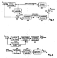
- a PCM audio input signal SPCM passes through a lossy encoder 81 to a lossy decoder 82 and as a lossy bit stream to a lossy decoder 85 of the decoding part (right side).
- Lossy encoding and decoding is used to de-correlate the signal.
- the output signal of decoder 82 is removed from the input signal SPCM in a subtractor 83, and the resulting difference signal passes through a lossless encoder 84 as an extension bit! stream to a lossless decoder 87.
- the output signals of decoders 85 and 87 are combined 86 so as to regain the original signal SPCM.
- the PCM audio input signal SPCM passes through an analysis filter bank 91 and a quantisation 92 of sub-band samples to a coding and bit stream packing 93.
- the quantisation is controlled by a perceptual model calculator 94 that receives signal SPCM and corresponding information from the analysis filter bank 91.
- the encoded lossy bit stream enters a means 95 for de-packing the bit stream, followed by means 96 for decoding the subband samples and by a synthesis filter bank 97 that outputs the decoded lossy PCM signal SDec.
- a problem to be solved by the invention is to provide hierarchical lossless audio encoding and decoding, which is build on top of an embedded lossy audio codec and which provides a better efficiency (i.e. compression ratio) as compared to state-of-the-art lossy based lossless audio coding schemes.
- This problem is solved by the methods disclosed in claims 1, 2, 5 and 6. Apparatuses that utilise these methods are disclosed in claims 3, 4, 7 and 8, respectively.
- This invention uses a mathematically lossless encoding and decoding on top of a lossy coding.
- Mathematically lossless audio compression means audio coding with bit-exact reproduction of the original PCM samples at decoder output.
- the lossy encoding operates in a transform domain, using e.g. frequency transforms like MDCT or similar filter banks.
- the mp3 standard ISO/IEC 11172-3 Layer 3 will be used for the lossy base layer throughout this description, but the invention can be applied together with other lossy coding schemes (e.g. AAC, MPEG-4 Audio) in a similar manner.
- the transmitted or recorded encoded bit stream comprises two parts: the embedded bit stream of the lossy audio codec, and extension data for one or several additional layers to obtain either the lossless (i.e. bit-exact) original PCM samples or intermediate qualities.
- the invention basically follows version c) of the above-listed concepts.
- inventive embodiments utilise features from concepts a) and b) as well, i.e. a synergistic combination of techniques from several ones of the state-of-the-art lossless audio coding schemes.
- the invention uses frequency domain de-correlation to prepare the residual signal (error signal) of the base-layer lossy audio codec for efficient lossless encoding.
- the proposed decorrelation techniques make use of side information that is extracted from the lossy decoder. Thereby, transmission of redundant information in the bit stream is prevented, and the overall compression ratio is improved.
- some embodiments of the invention provide the audio signal in one or several intermediate qualities (in the range limited by the lossy codec and mathematically lossless quality). Furthermore, the invention allows for stripping of the embedded lossy bit stream using a simple bit dropping technique.
- Two basic embodiments of the invention differ in the domain, in which the de-correlation of the residual signal of the lossy base layer codec takes place: in frequency domain, or in both time and frequency domains in a coordinated manner.
- all embodiments utilise information taken from the decoder of the lossy base-layer codec to control the de-correlation and lossless coding process.
- Some of the embodiments additionally use information from the encoder of the lossy base-layer codec.
- the exploitation of side information from the lossy base-layer codec allows for reduction of redundancies in the gross bit stream, thus improving the coding efficiency of the lossy based lossless codec.
- At least two different variants of the audio signal with different quality levels can be extracted from the bit stream. These variants include the signal represented by the embedded lossy coding scheme and the lossless decoding of the original PCM samples. In some embodiments (see section Decorrelation in frequency and time domain ) it is possible to decode one or several further variants of the audio signal with intermediate qualities.
- the inventive encoding method is suited for lossless encoding of a source signal, using a lossy encoded data stream and a lossless extension data stream which together form a lossless encoded data stream for said source signal, said method including the steps:
- the inventive decoding method is suited for decoding a lossless encoded source signal data stream, which data stream was derived from a lossy encoded data stream and a lossless extension data stream which together form a lossless encoded data stream for said source signal, wherein:
- inventive apparatuses carry out the functions of the corresponding inventive methods.
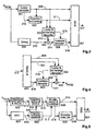
- a lossy encoder 301 uses some transform of the original signal S PCM (or a sub-band signal thereof) before quantising the transform coefficients using adaptive or fixed bit allocation. Without loss of generality, it is assumed in the following that the lossy encoder is based on a frequency transform.
- a 'spectral whitening' block 302 is applied the purpose of which is to determine the error signal of lossy coder 301 in the transform domain, and to perform additional quantisation of these error coefficients in order to achieve a spectrally flat (i.e.
- the spectral whitening block requires at least the original transform coefficients 310 and the quantised transform coefficients 309 contained in the bit stream as input signals. Such whithening can be achieved by quantising the error within the frequency domain.
- the difference signal between the original transform coefficients 310 and the quantised transform coefficients 309 in the frequency domain is a mirror or image of the difference signal 314 in the time domain.
- the output bit stream 309 of the lossy encoder and the additional information 311 from the spectral whitening block 302 are fed into an extended lossy and whitening decoder block 303 and to a multiplexer 307.
- the resulting time domain signal 312 is subtracted 305 from the properly delayed version 313 (compensating any delay of the lossy codec) of the original signal S PCM , producing a residual signal 314. Owing to the spectral whitening process, this residual signal has a flat spectrum, i.e. there is negligible correlation between successive samples.
- the residual signal can be directly fed into a lossless encoder 306 which outputs a lossless extension stream 316.
- side information (see the examples given above; in particular advantageous is the average power of the error signal) 315 from the lossy & whitening decoder 303 can be utilised to control the lossless encoder 306.
- the lossy & whitening decoder 303, subtractor 305 and any interpolation functionalities that may optionally be implemented inside the lossy decoder block are implemented in a platform-independent manner. That is, for all targeted platforms a fixed-point implementation with integer precision is required that produces bit-exactly reproducible results.
- Multiplexer 307 combines the partial bit streams 309, 311 and 316 to form output bit stream signal 317, and may produce different file formats or bit stream formats.
- the received bit stream 317 is de-multiplexed 401 and split into the individual signal layers 406, 407 and 408.
- Both the embedded lossy bit stream 406 and the spectral whitening bit stream 407 are fed into a lossy and whitening decoder 402.
- the resulting time domain signal 409 is a bit-exact replica of the intermediate-quality signal 312 in the encoding.
- a lossless decoder 403 gets inputs from bit stream 408 and optionally from the lossy and whitening decoder (side information 410) to produce the residual signal 411.
- the final output signal S PCM is obtained by adding the intermediate-quality signal 409 to the lossless decoded residual signal 411.
- elements 402, 403 and 404 are identical to that of the respective elements 303, 306 and 305.
- a tailored decoder may produce an output signal with an intermediate quality that is between the quality of the embedded lossy codec and the mathematically lossless decoding of the original PCM samples. This intermediate quality depends on the power of the residual signal, controlled in one of the manners described in the previous paragraph.
- Such decoder may not include the lossless decoder 403 and adder 404 and would not process bitstream 316/408.
- a layered organisation of the spectral whitening information 311 is possible.
- a codec can be specified which has an arbitrary number of intermediate quality levels in the range defined by the lossy codec (lowest quality) and the original PCM samples (highest quality).
- the different quality levels can be organised such as to provide a scalable bit stream.
- FIG. 5 A block diagram of an mp3 compliant encoder is shown in Fig. 5 .
- the mp3 encoder of Fig. 5 (possibly except MUX 507, depending on the bit stream or file format) is part of the lossy encoder block 301.
- the original input signal S PCM passes through a polyphase filter bank & decimator 503, a segmentation & MDCT 504 and a bit allocation and quantiser 505 to multiplexer 507.
- Input signal S PCM also passes through an FFT stage or step 501 to a psycho-acoustic analysis 502 which controls the segmentation (or windowing) in step/stage 504 and the quantisation 505.
- the bit allocation and quantiser 505 also provides side information 515 that passes through a side info encoder 506 to multiplexer 507 which outputs signal 517.
- x denote an individual but arbitrary original transform coefficient from the output vector 513 of block 504, i.e. in the MDCT domain for mp3, and let x ⁇ denote the quantised version of the same coefficient, represented and encoded by the bit stream 514, which is part of output signal 517 or 309, respectively.
- the original vector of MDCT coefficients 513 is passed on to the spectral whitening block 302.
- signal 310 comprises signal 513 and optionally additional useful side information from the mp3 encoder.
- spectral whitening quantiser known quantisation techniques can be used, e.g. scalar or lattice quantisation followed by entropy coding, or optimised (trained) fixed-entropy scalar or vector quantisation.
- scalar or lattice quantisation followed by entropy coding or optimised (trained) fixed-entropy scalar or vector quantisation.
- optimised (trained) fixed-entropy scalar or vector quantisation optimised (trained) fixed-entropy scalar or vector quantisation.
- This embodiment combines features described in the sections time domain de-correlation and frequency domain de-correlation.
- the de-correlation is split into two sub-systems, operating in frequency domain and in time domain, respectively.
- a lossy encoder 601 uses some transform of the original signal S PCM (or a sub-band signal thereof) before quantising the transform coefficients with adaptive or fixed bit allocation. Without loss of generality, it is assumed in the following that encoder 601 uses a frequency transform.
- a spectral whitening block 602 is applied the purpose of which is to determine the error signal of encoder 601 in the transform domain, and to perform additional quantisation of these error coefficients in order to achieve for consecutive values of the extension data signal to be encoded an error floor that is spectrally more flat or white than that of the input error spectrum of the lossy decoder.
- the spectral whitening block requires at least the original transform coefficients 613 and the quantised transform coefficients 612 as input signals.
- the output bit stream 612 of the lossy encoder and the corresponding additional information 614 from the spectral whitening block 602 are fed to a lossy and whitening decoder block 603 and to a multiplexer 610. Its resulting time domain output signal 615 is subtracted 605 from the properly delayed version 616 of the original signal S PCM , producing a residual signal 617.
- the still remaining weak correlation between successive samples of the residual signal 617 is removed in a linear prediction filter 607.
- the side information (see the examples given above, e.g. the envelope of the error spectrum) 618 that is extracted from the lossy and whitening decoder block 603 is used in a filter adaptation block 606 to determine a set 621 of optimum filter coefficients to be applied in filter 607.
- the aim of the prediction filtering and the subtraction 608 is to produce a completely de-correlated output signal 623 with a flat or white spectrum.
- This residual signal passes through a lossless encoder 609 which outputs a lossless extension stream 624.
- side information see the examples given above, e.g.
- the signal power) 620 from filter adaptation block 606 can be utilised to control encoder 609.
- Information from block 606 about the prediction filter settings is optionally sent to multiplexer 610.
- the corresponding information stream 619 is always lower in data rate than for systems without exploitation of side information 618.
- Multiplexer 610 combines the partial bit streams 612, 614, 619 and 624 to form output signal 625, and may produce different file formats or bit stream formats.
- the received bit stream 625 is split by a demultiplexer 701 into the individual signal layers 709, 710, 711 and 712. Both, the embedded lossy bit stream 709 and the spectral whitening bit stream 710, are fed to a lossy and whitening decoder 702. Its lossy or intermediate-quality time domain output signal 719 is a bit-exact replica of the lossy or intermediate-quality signal 615 in the encoding.
- Decoder 702 also provides side information 713 to a filter adaptation block 703. From this side information and any optional bit stream components 711 (corresponding to signal 619 in Fig. 6 ), a filter adaptation is performed exactly like in the corresponding encoding block 606.
- a lossless decoder 704 gets inputs from lossless extension bit stream 712 and optionally from side information 715 (corresponding to side information 620 in Fig. 6 ) output by filter adaptation block 703, to produce the (partially) decorrelated residual signal 717 (corresponds to signal 623 in Fig. 6 ). That signal is fed to an inverse de-correlation filter comprising an adder 705 and a prediction filter 706 that is controlled by the filter coefficients 714 provided by block 703, thus producing a bit-exact replica 718 of the residual signal 617.
- the final output signal S PCM is obtained by combining in adder 707 the lossy decoded signal 719 and the lossless decoded residual signal 718.
- Filter coefficients 714 are identical to filter coefficients 621.
- elements 702, 704, 705, 706 and 707 are identical to that of the respective elements 603, 609, 608, 607 and 605.
- One strategy to control the balance between frequency and time domain de-correlation is to constrain the summed data rate of the lossy part and spectral whitening part of the bit stream. If there is a fixed upper limit to the data rate of these two components of the bit stream, the spectral whitening can only perform a certain portion of the task of de-correlation of the error signal. That is, the time domain residual signal 617 will still exhibit a certain amount of correlation. This remaining correlation is removed by the downstream time domain de-correlation using linear prediction filtering, exploiting information taken from the lossy & whitening decoder
- Another strategy is to use frequency domain de-correlation only to remove long-term correlation from the residual signal, i.e. correlation characteristics of the signal which are narrow (or 'peaky') in frequency domain, corresponding to tonal components of the residual signal. Subsequently, the time domain de-correlation by linear prediction filtering is optimised and used to remove the remaining short-term correlation from the residual signal.
- both de-correlation techniques are used in their specifically best operation points. Hence, this kind of processing allows very efficient encoding with low computational complexity.
- a tailored decoder may produce an output signal with an intermediate quality that is between the quality of the embedded lossy codec and the mathematically lossless decoding of the original PCM samples. This intermediate quality depends on the power of the residual signal, controlled in one of the manners described in the previous paragraph.
- Such decoder may not include the lossless decoder 704, filter adaptation block 703, prediction filter 706 and adders 705 and 707.
Landscapes
- Engineering & Computer Science (AREA)
- Physics & Mathematics (AREA)
- Health & Medical Sciences (AREA)
- Signal Processing (AREA)
- Audiology, Speech & Language Pathology (AREA)
- Human Computer Interaction (AREA)
- Computational Linguistics (AREA)
- Acoustics & Sound (AREA)
- Multimedia (AREA)
- Quality & Reliability (AREA)
- Spectroscopy & Molecular Physics (AREA)
- Theoretical Computer Science (AREA)
- Compression, Expansion, Code Conversion, And Decoders (AREA)
Claims (13)
- Verfahren zum verlustlosen Kodieren eines Quellensignals (SPCM) unter Verwendung eines verlustbehaftet kodierten Datenstroms (309,612) und eines verlustlosen Erweiterungsdatenstroms (316,624), die zusammen einen verlustlos kodierten Datenstrom (317,625) für das Quellensignal bilden, wobei das Verfahren die Schritte einschließt:- Verlustbehaftetes Kodieren (301,601) des Quellensignals, wobei das verlustbehaftete Kodieren den verlustbehaftet kodierten Datenstrom (309,612) liefert, gekennzeichnet durch:Berechnen (302,602) spektraler weißmachender Daten (311, 614) aus quantisierten Koeffizienten des verlustbehaftet kodierten Datenstroms und entsprechenden noch nicht quantisierten, aus der verlustbehafteten Kodierung empfangenen Koeffizienten, wobei die spektralen weißmachenden Daten eine feinere Quantisierung der ursprünglichen Koeffizienten darstellen, und wobei die Berechnung so gesteuert wird, dass als Ziel die Leistung des quantisierten Fehlers für alle Frequenzen konstant ist;- verlustbehaftetes Dekodieren (303,603) der verlustbehaftet kodierten Daten unter Verwendung der spektralen weißmachenden Daten, um dadurch ein dekodiertes Signal (312,615) zu rekonstruieren;- Bilden (305,605) eines Differenzsignals (314,617) zwischen einer entsprechend verzögerten (304,604) Version des Quellensignals (SPCM) und dem dekodierten Signal (312, 615);- Verlustloses Kodieren (306, 309) des Differenzsignals, um den verlustlosen Erweiterungsdatenstrom (316,624) bereitzustellen;- Kombinieren (307,610)des verlustlosen Erweiterungsdatenstroms mit dem verlustbehaftet kodierten Datenstrom und den spektralen weißmachenden Daten (311,614), um den verlustlos kodierten Datenstrom zu (317,625) bilden.
- Verfahren nach Anspruch 1, das die weiteren Schritte einschliesst;- Bereitstellen von Seiteninformationen (618) bei dem verlustbehafteten Dekodieren (603) der verlustbehaftet kodierten Daten unter Verwendung der spektralen weißmachenden Daten zur Steuerung eines Zeitbereichs-Vorhersagefilters;- Vorhersagefilterung (607, 608) des Differenzsignals (617) unter Verwendung von Filterkoeffizienten (621), die von den Seiteninformationen abgeleitet werden (606), um so in dem Zeitbereich die aufeinanderfolgenden Werte des Differenzsignals zu entkorrelieren (617);- wenn verlustlos kodiert wird, Kodieren (609) des entkorrelierten Differenzsignals (623) anstelle des Differenzsignals (314, 617).
- Vorrichtung zum verlustlosen Kodieren eines Quellensignals (SPCM) unter Verwendung eines verlustbehaftet kodierten Datenstroms (309, 612) und eines verlustlosen Erweiterungsdatenstroms (316, 624), die zusammen einen verlustlos kodierten Datenstrom (317,625) für das Quellensignal bilden, wobei die Vorrichtung einschliesst:- Mittel (301,601) zum verlustbehafteten Kodieren des Quellensignals, wobei das verlustbehaftete Kodieren den verlustbehaftet kodierten Datenstrom (309,612) liefert, gekennzeichnet durch:- Mittel (302,602) zum Berechnen spektraler weißmachender Daten (311,614) aus quantisierten Koeffizienten des verlustbehaftet kodierten Datenstroms und entsprechenden noch nicht quantisierten, aus der verlustbehafteten Kodierung empfangenen Koeffizienten, wobei die spektralen weißmachenden Daten eine feinere Quantisierung der ursprünglichen Koeffizienten, darstellen, und wobei die Berechnung so gesteuert wird, dass als Ziel die Leistung des quantisierten Fehlers für alle Frequenzen konstant ist;- Mittel (303,609) zum verlustbehafteten Dekodieren der verlustbehaftet kodierten Daten unter Verwendung der spektralen weißmachenden Daten, um dadurch ein dekodiertes Signal (312,615) zu rekonstruieren;- Mittel (305,304,605,604) zum Bilden eines Differenzsignals (314,617) zwischen einer entsprechend verzögerten Version des Quellensignals (SPCM) und dem dekodierten Signal (312,615);- Mittel (306,609) zum verlustlosen Kodieren des Differenzsignals, um den verlustlosen Erweiterungsdatenstrom (316,624) bereitzustellen;- Mittel (307,610) zum Kombinieren des verlustlosen Erweiterungsdatenstroms mit dem verlustbehaftet kodierten Datenstrom und den spektralen weißmachenden Daten (311,614), um den verlustlos kodierten Datenstrom (317,625) zu bilden.
- Vorrichtung nach Anspruch 3, bei der:- in den verlustbehafteten Dekodiermitteln (603) Seiteninformationen (618) zur Steuerung eines Zeitbereichs-Vorhersagefilters bereitgestellt werden;- Mittel (607,608) zur Vorhersagefilterung des Differenzsignals (617) unter Verwendung von Filterkoeffizienten (621), die von den Seiteninformationen abgeleitet werden, vorgesehen sind,um so in dem Zeitbereich die aufeinanderfolgenden Werte des Differenzsignals (617)zu entkorrelieren;- in den verlustlosen Kodiermitteln das entkorrelierte Differenzsignal (623)anstelle des Differenzsignals 314, 617) kodiert (609) wird.
- Verfahren zum Dekodieren eines verlustlos kodierten Quellensignal-(SPCM)-Datenstroms, der von einem verlustbehaftet kodierten Datenstrom (309,612) und einem verlustlosen Erweiterungsdatenstrom (316,624) abgeleitet wurde, die zusammen einen verlustlos kodierten Datenstrom (317,625) für das Quellensignal bilden, bei dem:- das Quellensignal verlustbehaftet kodiert wurde (301, 601), das verlustbehaftete Kodieren den verlustbehaftet kodierten Datenstrom (309, 612) liefert;- spektrale weißmachende Daten (311,614) aus quantisierten Koeffizienten des verlustbehaftet kodierten Datenstroms berechnet wurden (302,602) und entsprechende noch nicht quantisierte Koeffizienten aus der verlustbehafteten Kodierung empfangen wurden, wobei die spektralen weißmachenden Daten eine feinere Quantisierung der ursprünglichen Koeffizienten darstellen, wodurch die Berechnung so gesteuert wurde, dass als Ziel die Leistung des quantisierten Fehlers für alle Frequenzen konstant ist;- die verlustbehaftet kodierten Daten verlustbehaftet unter Verwendung der spektralen weißmachenden Daten dekodiert wurden (303,603), wodurch ein dekodiertes Signal (312,615) rekonstruiert wurde;- ein Differenzsignal (314,617) zwischen einer entsprechend verzögerten (304,604) Version des Quellensignals (SPCM) und des dekodierten Signals (312,615) gebildet wurde (305,605);- das Differenzsignal verlustlos kodiert wurde (306,609), um den verlustlosen Erweiterungsdatenstrom zu liefern;- der verlustlose Erweiterungsdatenstrom mit dem verlustbehaftet kodierten Datenstrom und den spektralen weißmachenden Daten (311,614) kombiniert wurde (307,610), um den verlustlos kodierten Datenstrom (317,625) zu bilden, wobei das Verfahren die Schritte einschliesst:- Demultiplexen (401,701) des verlustlos kodierten Quellensignaldatenstroms (317,625), um den verlustlosen Erweiterungsdatenstrom (408,712), den verlustbehaftet kodierten Datenstrom (406,709) und die spektralen weißmachenden Daten (407,710) bereitzustellen;- verlustbehaftetes Dekodieren (402,702) des verlustbehaftet kodierten Datenstroms unter Verwendung der spektralen weißmachenden Daten (407,710), um dadurch ein verlustbehaftet dekodiertes Signal (400,719) zu rekonstruieren;- Dekodieren (403,704) des verlustlosen Erweiterungsdatenstroms, um so das Differenzsignal (411,717) zu liefern;- Kombinieren (404,707) des Differenzsignals (411,717) mit dem verlustbehaftet dekodierten Signal (409,719), um das Quellensignal (SPCM) zu rekonstruieren.
- Verfahren nach Anspruch 5, bei dem auf der Kodiererseite:Bei der verlustbehafteten Dekodierung (603) der verlustbehaftet kodierten Daten unter Verwendung der spektralen weißmachenden Daten Seiteninformationen (618) zur Steuerung eines Zeitbereichs-Vorhersagefilters bereitgestellt wurden;das Differenzsignal unter Verwendung von Filterkoeffizienten (621), die von den Seiteninformationen abgeleitet wurden (606), vorhersagegefiltert wurde (607,608), um in dem Zeitbereich die aufeinanderfolgenden Werte des Differenzsignals zu entkorrelieren;- bei der verlustlosen Kodierung das entkorrelierte Differenzsignal (623) anstelle des Differenzsignals (314,617) kodiert (609) wurde, wobei das Verfahren auf der Dekodiererseite die weiteren Schritte einschließt:- Bei der verlustlosen Dekodierung (702) Bereitstellen von Seiteninformationen (713) zur Steuerung eines Zeitbereichs-Vorhersagefilters (705,706);- inverse Entkorrelationsfilterung (705,706) aufeinanderfolgender Werte des entkorrelierten Differenzsignals unter Verwendung von Filterkoeffizienten (714), die aus den Seiteninformationen (713) abgeleitet wurden (703);- anstelle des Differenzsignals (411), Kombinieren (707) des entkorrelationsgefilterten Differenzsignals (718) mit dem verlustbehaftet dekodierten Signal (719), um das Quellensignal (SPCM) zu rekonstruieren.
- Vorrichtung zum Dekodieren eines verlustlos kodierten Quellensignal-(SPCM)-Datenstroms, der aus einem verlustbehaftet kodierten Datenstrom (309,612) und einem verlustlosen Erweiterungsdatenstrom (316,624) abgeleitet wurde, die zusammen einen verlustlos kodierten Datenstrom (317,625) bilden, wobei:- Das Quellensignal verlustbehaftet kodiert wurde (301,601) und die verlustbehaftete Kodierung den verlustbehaftet kodierten Datenstrom (309,612) liefert;- spektrale weißmachende Daten (311,614) aus quantisierten Koeffizienten des verlustbehaftet kodierten Datenstroms und entsprechenden noch nicht quantisierten, aus der verlustbehafteten Kodierung empfangenen Koeffizienten berechnet wurden (302,602), wobei die spektralen weißmachenden Daten eine feinere Quantisierung der ursprünglichen Koeffizienten darstellen, wodurch die Berechnung so gesteuert wurde, dass als Ziel die Leistung des quantisierten Fehlers für'alle Frequenzen konstant ist;- die verlustbehaftet kodierten Daten verlustbehaftet unter Verwendung der spektralen weißmachenden Daten dekodiert wurden (303,603), wodurch ein dekodiertes Signal (312,615) rekonstruiert wurde;- ein Differenzsignal (314,617) zwischen einer entsprechend verzögerten (304,604) Version des Quellensignals (SPCM) und des dekodierten Signals (312,615) gebildet wurde (305,605);- das Differenzsignal verlustlos kodiert wurde (306,609), um den verlustlosen Erweiterungsdatenstrom (316,624) zu liefern;- der verlustlose Erweiterungsdatenstrom mit dem verlustbehaftet kodierten Datenstrom und den spektralen weißmachenden Daten (311,614) kombiniert (307,610) wurde, um den verlustlos kodierten Datenstroms (317,625) zu bilden, wobei die Vorrichtung einschliesst:- Mittel (401,701) zum Demultiplexen des verlustlos kodierten Quellensignaldatenstroms (317,625), um den verlustlosen Erweiterungsdatenstrom (408,712), den verlustbehaftet kodierten Datenstrom (406,709) und die spektralen weißmachenden Daten (407,710) bereitzustellen;- Mittel (402,702) zum verlustbehafteten Dekodieren des veerlustbehaftet kodierten Datenstroms unter Verwendung der spektralen weißmachender Daten (407,710), um dadurch ein verlustbehaftet dekodiertes Signal (409,719) zu rekonstruieren;- Mittel (403,704) zum Dekodieren des verlustlosen Erweiterungsdatenstroms, um so das Differenzsignal (411,717) zu liefern;- Mittel (404,704) zum Kombinieren des Differenzsignals (411,717) mit dem verlustbehaftet dekodierten Signal (409,719), um das Quellensignal (SPCM) zu rekonstruieren.
- Vorrichtung nach Anspruch 7, bei dem auf der Kodiererseite:Bei der verlustbehafteten Dekodierung (603) der verlustbehaftet kodierten Daten unter Verwendung der spektralen weißmachenden Daten Seiteninformationen (618) zur Steuerung eines Zeitbereichs-Vorhersagefilters bereitgestellt wurden;das Differenzsignal unter Verwendung von Filterkoeffizienten (621), die von den Seiteninformationen abgeleitet wurden (606), vorhersagegefiltert wurde (607,608), um in dem Zeitbereich die aufeinanderfolgenden Werte des Differenzsignals zu entkorrelieren;bei der verlustlosen Kodierung das entkorrelierte Differenzsignal (623) anstelle des Differenzsignals (314,617) kodiert wurde, wobei die Vorrichtung einschliesst:- In den verlustbehafteten Dekodiermitteln (702) vorgesehene Seiteninformationen (713) zur Steuerung eines Zeitbereichs-Vorhersagefilters (705,706);- Mittel (705,706) zur inversen Entkorrelationsfilterung aufeinanderfolgender Werte des entkorrelierten Differenzsignals unter Verwendung von Filterkoeffizienten (714), die aus den Seiteninformationen (713) abgeleitet werden (703);- Kombinieren in den Kombinationsmitteln (707) anstelle des Differenzsignals (718) das entkorrelationsgefilterte Differenzsignal (718) mit dem verlustbehaftet dekodierten Signal (719), um das Quellensignal (SPCM) zu rekonstruieren.
- Verfahren nach Anspruch 2 oder 6 oder Vorrichtung nach Anspruch 4 oder 8, bei dem bzw. bei der aus den Seiteninformationen (618) Vorhersagefilter-Einstellungsdaten (619) abgeleitet und in den verlustlos kodierten Datenstrom (625) eingeschlossen werden bzw. Vorhersagefilter-Einstellungsdaten (711) aus den Seiteninformationen dem verlustlos kodierten Datenstrom (625) entnommen und zur Erzeugung (703) der Vorhersagefilterkoeffizienten (714) verwendet werden.
- Verfahren nach einem der Ansprüche 2, 6 und 9 oder Vorrichtung nach einem der Ansprüche 4, 8 und 9, bei dem bzw. bei der die Standardabweichung (620,715) des Vorhersagerestes verwendet wird, um die verlustlose Kodierung (609) zu parametrieren bzw. die verlustlose Dekodierung zu steuern.
- verfahren nach Anspruch 1 oder 5 oder Vorrichtung nach Anspruch 3 oder 7, bei dem bzw. bei der die Seiteninformationen (315,410) aus dem verlustbehafteten Dekodierer verwendet werden, um die verlustlose Kodierung (306) bzw. die verlustlose Dekodierung (403) zu steuern.
- Verfahren nach Anspruch 5 oder 6 oder Vorrichtung nach Anspruch 7 oder 8, bei dem bzw. bei der verlustlose Erweiterungsdatenstrom (408, 712) nicht bewertet wird und die spektralen weißmachenden Daten (407,710) zusammen mit dem verlustbehaftet kodierten Datenstrom (406,709) verwendet werden, um ein Ausgangssignal zu dekodieren (402,702), das eine mittlere Qualität hat, die kleiner ist als die des Quellensignals.
- Speichermedium, z.B. eine optische Disk, das ein digitales Signal enthält oder speichert, das gemäss dem Verfahren eines der Ansprüche 1, 2 und 9 bis 11 kodiert ist oder auf dem ein solches Signal aufgezeichnet ist.
Priority Applications (2)
| Application Number | Priority Date | Filing Date | Title |
|---|---|---|---|
| EP12154030A EP2453437A3 (de) | 2006-05-05 | 2007-04-18 | Verfahren und Vorrichtung für verlustfreie Kodierung eines Quellensignals unter Verwendung eines verlustbehafteten kodierten Datenstroms und eines verlustfreien Erweiterungsdatenstroms |
| EP07728246A EP2016583B1 (de) | 2006-05-05 | 2007-04-18 | Verfahren und vorrichtung zur verlustlosen codierung eines quellensignals unter verwendung eines verlustbehaftet codierten datenstroms und eines verlustlosen erweiterungsdatenstroms |
Applications Claiming Priority (3)
| Application Number | Priority Date | Filing Date | Title |
|---|---|---|---|
| EP06113596A EP1852849A1 (de) | 2006-05-05 | 2006-05-05 | Verfahren und Vorrichtung für verlustfreie Kodierung eines Quellensignals unter Verwendung eines verlustbehafteten kodierten Datenstroms und eines verlustfreien Erweiterungsdatenstroms |
| PCT/EP2007/053784 WO2007128662A1 (en) | 2006-05-05 | 2007-04-18 | Method and apparatus for lossless encoding of a source signal, using a lossy encoded data stream and a lossless extension data stream |
| EP07728246A EP2016583B1 (de) | 2006-05-05 | 2007-04-18 | Verfahren und vorrichtung zur verlustlosen codierung eines quellensignals unter verwendung eines verlustbehaftet codierten datenstroms und eines verlustlosen erweiterungsdatenstroms |
Related Child Applications (1)
| Application Number | Title | Priority Date | Filing Date |
|---|---|---|---|
| EP12154030A Division-Into EP2453437A3 (de) | 2006-05-05 | 2007-04-18 | Verfahren und Vorrichtung für verlustfreie Kodierung eines Quellensignals unter Verwendung eines verlustbehafteten kodierten Datenstroms und eines verlustfreien Erweiterungsdatenstroms |
Publications (2)
| Publication Number | Publication Date |
|---|---|
| EP2016583A1 EP2016583A1 (de) | 2009-01-21 |
| EP2016583B1 true EP2016583B1 (de) | 2012-08-15 |
Family
ID=36589352
Family Applications (3)
| Application Number | Title | Priority Date | Filing Date |
|---|---|---|---|
| EP06113596A Withdrawn EP1852849A1 (de) | 2006-05-05 | 2006-05-05 | Verfahren und Vorrichtung für verlustfreie Kodierung eines Quellensignals unter Verwendung eines verlustbehafteten kodierten Datenstroms und eines verlustfreien Erweiterungsdatenstroms |
| EP07728246A Not-in-force EP2016583B1 (de) | 2006-05-05 | 2007-04-18 | Verfahren und vorrichtung zur verlustlosen codierung eines quellensignals unter verwendung eines verlustbehaftet codierten datenstroms und eines verlustlosen erweiterungsdatenstroms |
| EP12154030A Withdrawn EP2453437A3 (de) | 2006-05-05 | 2007-04-18 | Verfahren und Vorrichtung für verlustfreie Kodierung eines Quellensignals unter Verwendung eines verlustbehafteten kodierten Datenstroms und eines verlustfreien Erweiterungsdatenstroms |
Family Applications Before (1)
| Application Number | Title | Priority Date | Filing Date |
|---|---|---|---|
| EP06113596A Withdrawn EP1852849A1 (de) | 2006-05-05 | 2006-05-05 | Verfahren und Vorrichtung für verlustfreie Kodierung eines Quellensignals unter Verwendung eines verlustbehafteten kodierten Datenstroms und eines verlustfreien Erweiterungsdatenstroms |
Family Applications After (1)
| Application Number | Title | Priority Date | Filing Date |
|---|---|---|---|
| EP12154030A Withdrawn EP2453437A3 (de) | 2006-05-05 | 2007-04-18 | Verfahren und Vorrichtung für verlustfreie Kodierung eines Quellensignals unter Verwendung eines verlustbehafteten kodierten Datenstroms und eines verlustfreien Erweiterungsdatenstroms |
Country Status (8)
| Country | Link |
|---|---|
| US (1) | US8326618B2 (de) |
| EP (3) | EP1852849A1 (de) |
| JP (1) | JP5215994B2 (de) |
| KR (1) | KR101473016B1 (de) |
| CN (1) | CN101432802B (de) |
| BR (1) | BRPI0711272A2 (de) |
| PT (1) | PT2016583E (de) |
| WO (1) | WO2007128662A1 (de) |
Families Citing this family (21)
| Publication number | Priority date | Publication date | Assignee | Title |
|---|---|---|---|---|
| US7620673B2 (en) * | 2005-09-19 | 2009-11-17 | The United States Of America As Represented By The Secretary Of The Air Force | Complimentary discrete fourier transform processor |
| US8392176B2 (en) | 2006-04-10 | 2013-03-05 | Qualcomm Incorporated | Processing of excitation in audio coding and decoding |
| EP1881485A1 (de) * | 2006-07-18 | 2008-01-23 | Deutsche Thomson-Brandt Gmbh | Audiobitstromdatenstruktur eines verlustbehafteten kodierten Signals mit verlustfreien Erweiterungkodierungsdaten für ein solches Signal. |
| US20090198500A1 (en) * | 2007-08-24 | 2009-08-06 | Qualcomm Incorporated | Temporal masking in audio coding based on spectral dynamics in frequency sub-bands |
| US8428957B2 (en) | 2007-08-24 | 2013-04-23 | Qualcomm Incorporated | Spectral noise shaping in audio coding based on spectral dynamics in frequency sub-bands |
| WO2009081315A1 (en) * | 2007-12-18 | 2009-07-02 | Koninklijke Philips Electronics N.V. | Encoding and decoding audio or speech |
| AU2009267532B2 (en) | 2008-07-11 | 2013-04-04 | Fraunhofer-Gesellschaft Zur Foerderung Der Angewandten Forschung E.V. | An apparatus and a method for calculating a number of spectral envelopes |
| PL2352147T3 (pl) * | 2008-07-11 | 2014-02-28 | Fraunhofer Ges Forschung | Urządzenie i sposób kodowania sygnału audio |
| EP2645366A4 (de) | 2010-11-22 | 2014-05-07 | Ntt Docomo Inc | Audiokodierungsvorrichtung, -verfahren und -programm sowie audiodekodierungsvorrichtung, -verfahren und -programm |
| MX2013005652A (es) | 2010-11-26 | 2013-09-13 | Nec Corp | Dispositivo de codificacion de video, dispositivo de decodificacion de video, metodo de codificacion de video, metodo de decodificacion de video, y programa. |
| CN102446509B (zh) * | 2011-11-22 | 2014-04-09 | 中兴通讯股份有限公司 | 增强抗丢包的音频编解码方法及系统 |
| GB201210373D0 (en) * | 2012-06-12 | 2012-07-25 | Meridian Audio Ltd | Doubly compatible lossless audio sandwidth extension |
| CN106941004B (zh) | 2012-07-13 | 2021-05-18 | 华为技术有限公司 | 音频信号的比特分配的方法和装置 |
| EP2830055A1 (de) | 2013-07-22 | 2015-01-28 | Fraunhofer-Gesellschaft zur Förderung der angewandten Forschung e.V. | Kontextbasierte Entropiecodierung von Probenwerten einer spektralen Hüllkurve |
| ES2934591T3 (es) | 2013-09-13 | 2023-02-23 | Samsung Electronics Co Ltd | Procedimiento de codificación sin pérdidas |
| US9779739B2 (en) * | 2014-03-20 | 2017-10-03 | Dts, Inc. | Residual encoding in an object-based audio system |
| KR20160145711A (ko) * | 2014-04-17 | 2016-12-20 | 아우디맥스, 엘엘씨 | 정보 손실을 감소시킨 전자 통신들을 위한 시스템들, 방법들 및 디바이스들 |
| WO2016142002A1 (en) * | 2015-03-09 | 2016-09-15 | Fraunhofer-Gesellschaft Zur Foerderung Der Angewandten Forschung E.V. | Audio encoder, audio decoder, method for encoding an audio signal and method for decoding an encoded audio signal |
| GB2624686B (en) * | 2022-11-25 | 2025-07-23 | Lenbrook Industries Ltd | Improvements to audio coding |
| CN118522296A (zh) * | 2023-02-17 | 2024-08-20 | 华为技术有限公司 | 有损编解码器和无损编解码器之间的切换方法和装置 |
| US20250078845A1 (en) * | 2023-08-29 | 2025-03-06 | Samsung Electronics Co., Ltd. | Lossless audio coding for multichannel hierarchical reconstruction |
Family Cites Families (17)
| Publication number | Priority date | Publication date | Assignee | Title |
|---|---|---|---|---|
| US5794179A (en) | 1995-07-27 | 1998-08-11 | Victor Company Of Japan, Ltd. | Method and apparatus for performing bit-allocation coding for an acoustic signal of frequency region and time region correction for an acoustic signal and method and apparatus for decoding a decoded acoustic signal |
| US6154484A (en) * | 1995-09-06 | 2000-11-28 | Solana Technology Development Corporation | Method and apparatus for embedding auxiliary data in a primary data signal using frequency and time domain processing |
| JPH10105200A (ja) | 1996-09-26 | 1998-04-24 | Toshiba Corp | 音声符号化/復号化方法 |
| DE19742201C1 (de) * | 1997-09-24 | 1999-02-04 | Fraunhofer Ges Forschung | Verfahren und Vorrichtung zum Codieren von Audiosignalen |
| DE69944788C5 (de) * | 1998-04-09 | 2023-10-19 | Koninklijke Philips N.V. | Verlustfreie kodierung/dekodierung in einem übertragungssystem |
| US6226616B1 (en) | 1999-06-21 | 2001-05-01 | Digital Theater Systems, Inc. | Sound quality of established low bit-rate audio coding systems without loss of decoder compatibility |
| SE0004163D0 (sv) * | 2000-11-14 | 2000-11-14 | Coding Technologies Sweden Ab | Enhancing perceptual performance of high frequency reconstruction coding methods by adaptive filtering |
| KR100908114B1 (ko) * | 2002-03-09 | 2009-07-16 | 삼성전자주식회사 | 스케일러블 무손실 오디오 부호화/복호화 장치 및 그 방법 |
| JP2003280694A (ja) * | 2002-03-26 | 2003-10-02 | Nec Corp | 階層ロスレス符号化復号方法、階層ロスレス符号化方法、階層ロスレス復号方法及びその装置並びにプログラム |
| US7275036B2 (en) | 2002-04-18 | 2007-09-25 | Fraunhofer-Gesellschaft Zur Foerderung Der Angewandten Forschung E.V. | Apparatus and method for coding a time-discrete audio signal to obtain coded audio data and for decoding coded audio data |
| DE10217297A1 (de) * | 2002-04-18 | 2003-11-06 | Fraunhofer Ges Forschung | Vorrichtung und Verfahren zum Codieren eines zeitdiskreten Audiosignals und Vorrichtung und Verfahren zum Decodieren von codierten Audiodaten |
| US7536305B2 (en) * | 2002-09-04 | 2009-05-19 | Microsoft Corporation | Mixed lossless audio compression |
| US7328150B2 (en) * | 2002-09-04 | 2008-02-05 | Microsoft Corporation | Innovations in pure lossless audio compression |
| JP4293005B2 (ja) | 2004-02-04 | 2009-07-08 | 日本電気株式会社 | 音声音楽信号の符号化装置および復号装置 |
| JP4997098B2 (ja) | 2004-03-25 | 2012-08-08 | ディー・ティー・エス,インコーポレーテッド | スケーラブル可逆オーディオ・コーデック及びオーサリング・ツール |
| US7272567B2 (en) * | 2004-03-25 | 2007-09-18 | Zoran Fejzo | Scalable lossless audio codec and authoring tool |
| US8086465B2 (en) * | 2007-03-20 | 2011-12-27 | Microsoft Corporation | Transform domain transcoding and decoding of audio data using integer-reversible modulated lapped transforms |
-
2006
- 2006-05-05 EP EP06113596A patent/EP1852849A1/de not_active Withdrawn
-
2007
- 2007-04-18 BR BRPI0711272-6A patent/BRPI0711272A2/pt not_active IP Right Cessation
- 2007-04-18 EP EP07728246A patent/EP2016583B1/de not_active Not-in-force
- 2007-04-18 JP JP2009508302A patent/JP5215994B2/ja not_active Expired - Fee Related
- 2007-04-18 WO PCT/EP2007/053784 patent/WO2007128662A1/en not_active Ceased
- 2007-04-18 CN CN200780015604.1A patent/CN101432802B/zh not_active Expired - Fee Related
- 2007-04-18 PT PT07728246T patent/PT2016583E/pt unknown
- 2007-04-18 US US12/227,045 patent/US8326618B2/en not_active Expired - Fee Related
- 2007-04-18 EP EP12154030A patent/EP2453437A3/de not_active Withdrawn
-
2008
- 2008-11-04 KR KR1020087027070A patent/KR101473016B1/ko not_active Expired - Fee Related
Also Published As
| Publication number | Publication date |
|---|---|
| KR101473016B1 (ko) | 2014-12-15 |
| CN101432802A (zh) | 2009-05-13 |
| CN101432802B (zh) | 2015-04-01 |
| EP2016583A1 (de) | 2009-01-21 |
| PT2016583E (pt) | 2012-09-25 |
| BRPI0711272A2 (pt) | 2011-11-08 |
| KR20090007396A (ko) | 2009-01-16 |
| EP2453437A3 (de) | 2012-07-18 |
| US20090177478A1 (en) | 2009-07-09 |
| WO2007128662A1 (en) | 2007-11-15 |
| JP2009536364A (ja) | 2009-10-08 |
| US8326618B2 (en) | 2012-12-04 |
| EP2453437A2 (de) | 2012-05-16 |
| JP5215994B2 (ja) | 2013-06-19 |
| EP1852849A1 (de) | 2007-11-07 |
Similar Documents
| Publication | Publication Date | Title |
|---|---|---|
| EP2016583B1 (de) | Verfahren und vorrichtung zur verlustlosen codierung eines quellensignals unter verwendung eines verlustbehaftet codierten datenstroms und eines verlustlosen erweiterungsdatenstroms | |
| EP2044589B1 (de) | Verfahren und vorrichtung zur verlustlosen codierung eines quellensignals unter verwendung eines verlustbehaftet codierten datenstroms und eines verlustlosen erweiterungsdatenstroms | |
| AU2008316860B2 (en) | Scalable speech and audio encoding using combinatorial encoding of MDCT spectrum | |
| US8515767B2 (en) | Technique for encoding/decoding of codebook indices for quantized MDCT spectrum in scalable speech and audio codecs | |
| JP4043476B2 (ja) | スケーラブルエンコーディングのための方法および装置ならびにスケーラブルデコーディングのための方法および装置 | |
| EP2209114B1 (de) | Vorrichtung/Verfahren zur Sprachkodierung/Sprachdekodierung | |
| EP2133872B1 (de) | Codierungseinrichtung und codierungsverfahren | |
| WO2012053150A1 (ja) | 音声符号化装置および音声復号化装置 | |
| JPWO2009116280A1 (ja) | ステレオ信号符号化装置、ステレオ信号復号装置およびこれらの方法 | |
| JPWO2009057329A1 (ja) | 符号化装置、復号装置およびこれらの方法 | |
| Muin et al. | A review of lossless audio compression standards and algorithms | |
| KR100718487B1 (ko) | 디지털 음성 코더들에서의 고조파 잡음 가중 | |
| HK1144851A (en) | Technique for encoding/decoding of codebook indices for quantized mdct spectrum in scalable speech and audio codecs |
Legal Events
| Date | Code | Title | Description |
|---|---|---|---|
| PUAI | Public reference made under article 153(3) epc to a published international application that has entered the european phase |
Free format text: ORIGINAL CODE: 0009012 |
|
| 17P | Request for examination filed |
Effective date: 20081023 |
|
| AK | Designated contracting states |
Kind code of ref document: A1 Designated state(s): AT BE BG CH CY CZ DE DK EE ES FI FR GB GR HU IE IS IT LI LT LU LV MC MT NL PL PT RO SE SI SK TR |
|
| AX | Request for extension of the european patent |
Extension state: AL BA HR MK RS |
|
| RIN1 | Information on inventor provided before grant (corrected) |
Inventor name: WUEBBOLT, OLIVER Inventor name: BOEHM, JOHANNES Inventor name: KEILER, FLORIAN Inventor name: KORDON, SVEN Inventor name: JAX, PETER |
|
| RAP1 | Party data changed (applicant data changed or rights of an application transferred) |
Owner name: THOMSON LICENSING |
|
| 17Q | First examination report despatched |
Effective date: 20110926 |
|
| GRAP | Despatch of communication of intention to grant a patent |
Free format text: ORIGINAL CODE: EPIDOSNIGR1 |
|
| DAX | Request for extension of the european patent (deleted) | ||
| GRAS | Grant fee paid |
Free format text: ORIGINAL CODE: EPIDOSNIGR3 |
|
| GRAA | (expected) grant |
Free format text: ORIGINAL CODE: 0009210 |
|
| AK | Designated contracting states |
Kind code of ref document: B1 Designated state(s): AT BE BG CH CY CZ DE DK EE ES FI FR GB GR HU IE IS IT LI LT LU LV MC MT NL PL PT RO SE SI SK TR |
|
| REG | Reference to a national code |
Ref country code: GB Ref legal event code: FG4D Ref country code: CH Ref legal event code: EP Ref country code: AT Ref legal event code: REF Ref document number: 571183 Country of ref document: AT Kind code of ref document: T Effective date: 20120815 |
|
| REG | Reference to a national code |
Ref country code: IE Ref legal event code: FG4D |
|
| REG | Reference to a national code |
Ref country code: PT Ref legal event code: SC4A Free format text: AVAILABILITY OF NATIONAL TRANSLATION Effective date: 20120918 |
|
| REG | Reference to a national code |
Ref country code: DE Ref legal event code: R096 Ref document number: 602007024778 Country of ref document: DE Effective date: 20121011 |
|
| REG | Reference to a national code |
Ref country code: SE Ref legal event code: TRGR |
|
| REG | Reference to a national code |
Ref country code: NL Ref legal event code: T3 |
|
| REG | Reference to a national code |
Ref country code: AT Ref legal event code: MK05 Ref document number: 571183 Country of ref document: AT Kind code of ref document: T Effective date: 20120815 |
|
| PG25 | Lapsed in a contracting state [announced via postgrant information from national office to epo] |
Ref country code: FI Free format text: LAPSE BECAUSE OF FAILURE TO SUBMIT A TRANSLATION OF THE DESCRIPTION OR TO PAY THE FEE WITHIN THE PRESCRIBED TIME-LIMIT Effective date: 20120815 Ref country code: AT Free format text: LAPSE BECAUSE OF FAILURE TO SUBMIT A TRANSLATION OF THE DESCRIPTION OR TO PAY THE FEE WITHIN THE PRESCRIBED TIME-LIMIT Effective date: 20120815 Ref country code: LT Free format text: LAPSE BECAUSE OF FAILURE TO SUBMIT A TRANSLATION OF THE DESCRIPTION OR TO PAY THE FEE WITHIN THE PRESCRIBED TIME-LIMIT Effective date: 20120815 Ref country code: IS Free format text: LAPSE BECAUSE OF FAILURE TO SUBMIT A TRANSLATION OF THE DESCRIPTION OR TO PAY THE FEE WITHIN THE PRESCRIBED TIME-LIMIT Effective date: 20121215 Ref country code: CY Free format text: LAPSE BECAUSE OF FAILURE TO SUBMIT A TRANSLATION OF THE DESCRIPTION OR TO PAY THE FEE WITHIN THE PRESCRIBED TIME-LIMIT Effective date: 20120815 |
|
| PG25 | Lapsed in a contracting state [announced via postgrant information from national office to epo] |
Ref country code: GR Free format text: LAPSE BECAUSE OF FAILURE TO SUBMIT A TRANSLATION OF THE DESCRIPTION OR TO PAY THE FEE WITHIN THE PRESCRIBED TIME-LIMIT Effective date: 20121116 Ref country code: SI Free format text: LAPSE BECAUSE OF FAILURE TO SUBMIT A TRANSLATION OF THE DESCRIPTION OR TO PAY THE FEE WITHIN THE PRESCRIBED TIME-LIMIT Effective date: 20120815 Ref country code: LV Free format text: LAPSE BECAUSE OF FAILURE TO SUBMIT A TRANSLATION OF THE DESCRIPTION OR TO PAY THE FEE WITHIN THE PRESCRIBED TIME-LIMIT Effective date: 20120815 Ref country code: PL Free format text: LAPSE BECAUSE OF FAILURE TO SUBMIT A TRANSLATION OF THE DESCRIPTION OR TO PAY THE FEE WITHIN THE PRESCRIBED TIME-LIMIT Effective date: 20120815 |
|
| PG25 | Lapsed in a contracting state [announced via postgrant information from national office to epo] |
Ref country code: RO Free format text: LAPSE BECAUSE OF FAILURE TO SUBMIT A TRANSLATION OF THE DESCRIPTION OR TO PAY THE FEE WITHIN THE PRESCRIBED TIME-LIMIT Effective date: 20120815 Ref country code: ES Free format text: LAPSE BECAUSE OF FAILURE TO SUBMIT A TRANSLATION OF THE DESCRIPTION OR TO PAY THE FEE WITHIN THE PRESCRIBED TIME-LIMIT Effective date: 20121126 Ref country code: DK Free format text: LAPSE BECAUSE OF FAILURE TO SUBMIT A TRANSLATION OF THE DESCRIPTION OR TO PAY THE FEE WITHIN THE PRESCRIBED TIME-LIMIT Effective date: 20120815 Ref country code: EE Free format text: LAPSE BECAUSE OF FAILURE TO SUBMIT A TRANSLATION OF THE DESCRIPTION OR TO PAY THE FEE WITHIN THE PRESCRIBED TIME-LIMIT Effective date: 20120815 Ref country code: CZ Free format text: LAPSE BECAUSE OF FAILURE TO SUBMIT A TRANSLATION OF THE DESCRIPTION OR TO PAY THE FEE WITHIN THE PRESCRIBED TIME-LIMIT Effective date: 20120815 |
|
| PG25 | Lapsed in a contracting state [announced via postgrant information from national office to epo] |
Ref country code: IT Free format text: LAPSE BECAUSE OF FAILURE TO SUBMIT A TRANSLATION OF THE DESCRIPTION OR TO PAY THE FEE WITHIN THE PRESCRIBED TIME-LIMIT Effective date: 20120815 Ref country code: SK Free format text: LAPSE BECAUSE OF FAILURE TO SUBMIT A TRANSLATION OF THE DESCRIPTION OR TO PAY THE FEE WITHIN THE PRESCRIBED TIME-LIMIT Effective date: 20120815 |
|
| PLBE | No opposition filed within time limit |
Free format text: ORIGINAL CODE: 0009261 |
|
| STAA | Information on the status of an ep patent application or granted ep patent |
Free format text: STATUS: NO OPPOSITION FILED WITHIN TIME LIMIT |
|
| 26N | No opposition filed |
Effective date: 20130516 |
|
| PG25 | Lapsed in a contracting state [announced via postgrant information from national office to epo] |
Ref country code: BG Free format text: LAPSE BECAUSE OF FAILURE TO SUBMIT A TRANSLATION OF THE DESCRIPTION OR TO PAY THE FEE WITHIN THE PRESCRIBED TIME-LIMIT Effective date: 20121115 |
|
| REG | Reference to a national code |
Ref country code: DE Ref legal event code: R097 Ref document number: 602007024778 Country of ref document: DE Effective date: 20130516 |
|
| PG25 | Lapsed in a contracting state [announced via postgrant information from national office to epo] |
Ref country code: MC Free format text: LAPSE BECAUSE OF FAILURE TO SUBMIT A TRANSLATION OF THE DESCRIPTION OR TO PAY THE FEE WITHIN THE PRESCRIBED TIME-LIMIT Effective date: 20120815 |
|
| REG | Reference to a national code |
Ref country code: CH Ref legal event code: PL |
|
| PG25 | Lapsed in a contracting state [announced via postgrant information from national office to epo] |
Ref country code: LI Free format text: LAPSE BECAUSE OF NON-PAYMENT OF DUE FEES Effective date: 20130430 Ref country code: CH Free format text: LAPSE BECAUSE OF NON-PAYMENT OF DUE FEES Effective date: 20130430 |
|
| PG25 | Lapsed in a contracting state [announced via postgrant information from national office to epo] |
Ref country code: MT Free format text: LAPSE BECAUSE OF FAILURE TO SUBMIT A TRANSLATION OF THE DESCRIPTION OR TO PAY THE FEE WITHIN THE PRESCRIBED TIME-LIMIT Effective date: 20120815 |
|
| REG | Reference to a national code |
Ref country code: FR Ref legal event code: PLFP Year of fee payment: 9 |
|
| PG25 | Lapsed in a contracting state [announced via postgrant information from national office to epo] |
Ref country code: TR Free format text: LAPSE BECAUSE OF FAILURE TO SUBMIT A TRANSLATION OF THE DESCRIPTION OR TO PAY THE FEE WITHIN THE PRESCRIBED TIME-LIMIT Effective date: 20120815 |
|
| PG25 | Lapsed in a contracting state [announced via postgrant information from national office to epo] |
Ref country code: LU Free format text: LAPSE BECAUSE OF NON-PAYMENT OF DUE FEES Effective date: 20130418 Ref country code: HU Free format text: LAPSE BECAUSE OF FAILURE TO SUBMIT A TRANSLATION OF THE DESCRIPTION OR TO PAY THE FEE WITHIN THE PRESCRIBED TIME-LIMIT; INVALID AB INITIO Effective date: 20070418 |
|
| PGFP | Annual fee paid to national office [announced via postgrant information from national office to epo] |
Ref country code: PT Payment date: 20150416 Year of fee payment: 9 Ref country code: SE Payment date: 20150413 Year of fee payment: 9 Ref country code: DE Payment date: 20150424 Year of fee payment: 9 Ref country code: GB Payment date: 20150427 Year of fee payment: 9 |
|
| PGFP | Annual fee paid to national office [announced via postgrant information from national office to epo] |
Ref country code: NL Payment date: 20150409 Year of fee payment: 9 Ref country code: FR Payment date: 20150421 Year of fee payment: 9 Ref country code: BE Payment date: 20150413 Year of fee payment: 9 Ref country code: IE Payment date: 20150409 Year of fee payment: 9 |
|
| REG | Reference to a national code |
Ref country code: DE Ref legal event code: R082 Ref document number: 602007024778 Country of ref document: DE Representative=s name: KASTEL PATENTANWAELTE, DE |
|
| REG | Reference to a national code |
Ref country code: DE Ref legal event code: R082 Ref document number: 602007024778 Country of ref document: DE |
|
| PG25 | Lapsed in a contracting state [announced via postgrant information from national office to epo] |
Ref country code: BE Free format text: LAPSE BECAUSE OF NON-PAYMENT OF DUE FEES Effective date: 20160430 |
|
| REG | Reference to a national code |
Ref country code: DE Ref legal event code: R119 Ref document number: 602007024778 Country of ref document: DE |
|
| REG | Reference to a national code |
Ref country code: SE Ref legal event code: EUG |
|
| REG | Reference to a national code |
Ref country code: NL Ref legal event code: MM Effective date: 20160501 |
|
| GBPC | Gb: european patent ceased through non-payment of renewal fee |
Effective date: 20160418 |
|
| REG | Reference to a national code |
Ref country code: IE Ref legal event code: MM4A |
|
| REG | Reference to a national code |
Ref country code: FR Ref legal event code: ST Effective date: 20161230 |
|
| PG25 | Lapsed in a contracting state [announced via postgrant information from national office to epo] |
Ref country code: GB Free format text: LAPSE BECAUSE OF NON-PAYMENT OF DUE FEES Effective date: 20160418 Ref country code: DE Free format text: LAPSE BECAUSE OF NON-PAYMENT OF DUE FEES Effective date: 20161101 Ref country code: NL Free format text: LAPSE BECAUSE OF NON-PAYMENT OF DUE FEES Effective date: 20160501 Ref country code: FR Free format text: LAPSE BECAUSE OF NON-PAYMENT OF DUE FEES Effective date: 20160502 |
|
| PG25 | Lapsed in a contracting state [announced via postgrant information from national office to epo] |
Ref country code: PT Free format text: LAPSE BECAUSE OF NON-PAYMENT OF DUE FEES Effective date: 20161018 Ref country code: SE Free format text: LAPSE BECAUSE OF NON-PAYMENT OF DUE FEES Effective date: 20160419 |
|
| PG25 | Lapsed in a contracting state [announced via postgrant information from national office to epo] |
Ref country code: IE Free format text: LAPSE BECAUSE OF NON-PAYMENT OF DUE FEES Effective date: 20160418 |