EP2016365B1 - Method of acquiring of at least a portion of the shape of a section of a spectacle frame circle - Google Patents
Method of acquiring of at least a portion of the shape of a section of a spectacle frame circle Download PDFInfo
- Publication number
- EP2016365B1 EP2016365B1 EP07731353A EP07731353A EP2016365B1 EP 2016365 B1 EP2016365 B1 EP 2016365B1 EP 07731353 A EP07731353 A EP 07731353A EP 07731353 A EP07731353 A EP 07731353A EP 2016365 B1 EP2016365 B1 EP 2016365B1
- Authority
- EP
- European Patent Office
- Prior art keywords
- bezel
- eyeglass frame
- shape
- frame
- category
- Prior art date
- Legal status (The legal status is an assumption and is not a legal conclusion. Google has not performed a legal analysis and makes no representation as to the accuracy of the status listed.)
- Active
Links
- 238000000034 method Methods 0.000 title claims abstract description 22
- 239000000700 radioactive tracer Substances 0.000 claims 1
- 239000000523 sample Substances 0.000 description 18
- 238000009966 trimming Methods 0.000 description 7
- 238000004891 communication Methods 0.000 description 5
- 239000011521 glass Substances 0.000 description 5
- 230000009466 transformation Effects 0.000 description 4
- 230000006870 function Effects 0.000 description 3
- 238000003754 machining Methods 0.000 description 3
- 230000003287 optical effect Effects 0.000 description 3
- 238000005259 measurement Methods 0.000 description 2
- 238000012546 transfer Methods 0.000 description 2
- 238000013519 translation Methods 0.000 description 2
- 241000254173 Coleoptera Species 0.000 description 1
- 229920000297 Rayon Polymers 0.000 description 1
- 238000012790 confirmation Methods 0.000 description 1
- 238000005520 cutting process Methods 0.000 description 1
- 210000000887 face Anatomy 0.000 description 1
- 238000003780 insertion Methods 0.000 description 1
- 230000037431 insertion Effects 0.000 description 1
- 238000013507 mapping Methods 0.000 description 1
- 239000007769 metal material Substances 0.000 description 1
- 238000004321 preservation Methods 0.000 description 1
- 210000001747 pupil Anatomy 0.000 description 1
- 239000002964 rayon Substances 0.000 description 1
- 230000003014 reinforcing effect Effects 0.000 description 1
- 230000004044 response Effects 0.000 description 1
- 230000000717 retained effect Effects 0.000 description 1
- 238000005096 rolling process Methods 0.000 description 1
- 238000007493 shaping process Methods 0.000 description 1
- 238000005728 strengthening Methods 0.000 description 1
- 238000010200 validation analysis Methods 0.000 description 1
Images

Classifications
-
- G—PHYSICS
- G01—MEASURING; TESTING
- G01B—MEASURING LENGTH, THICKNESS OR SIMILAR LINEAR DIMENSIONS; MEASURING ANGLES; MEASURING AREAS; MEASURING IRREGULARITIES OF SURFACES OR CONTOURS
- G01B5/00—Measuring arrangements characterised by the use of mechanical techniques
- G01B5/20—Measuring arrangements characterised by the use of mechanical techniques for measuring contours or curvatures
-
- G—PHYSICS
- G06—COMPUTING; CALCULATING OR COUNTING
- G06Q—INFORMATION AND COMMUNICATION TECHNOLOGY [ICT] SPECIALLY ADAPTED FOR ADMINISTRATIVE, COMMERCIAL, FINANCIAL, MANAGERIAL OR SUPERVISORY PURPOSES; SYSTEMS OR METHODS SPECIALLY ADAPTED FOR ADMINISTRATIVE, COMMERCIAL, FINANCIAL, MANAGERIAL OR SUPERVISORY PURPOSES, NOT OTHERWISE PROVIDED FOR
- G06Q30/00—Commerce
- G06Q30/06—Buying, selling or leasing transactions
- G06Q30/0601—Electronic shopping [e-shopping]
Definitions
- the present invention relates generally to the field of eyewear and more specifically to the acquisition of the shape of a circle of a spectacle frame rim type.
- It relates more particularly to a method of acquiring the shape of at least a portion of a section of a circle of an eyeglass frame chosen by a future carrier, comprising the acquisition of at least one geometrical characteristic of said section.
- the optician palpate the inner contour of each of the two circles of the selected eyeglass frame to precisely determine the coordinates of a plurality of points characterizing the shape of the strand longitudinal of the bezel of each circle.
- the knowledge of the shape of this strand allows the optician to deduce the shape that must present the contour of the corresponding lens, once cut and bevelled, in order to can be inserted into the relevant circle of the mount.
- the objective of this operation is in particular to follow exactly the bottom of the bezel of the circle to read, so as to memorize a precise digital image of the shape of the longitudinal strand of the bezel.
- the optician may, as the patent application discloses. FR 05 12457 and the patent EP 0 819 967 of the applicant, carry out another acquisition operation by probing the shape of a section of the bezel, so as to predict how the bevel of the ophthalmic lens will fit into the bezel.
- the acquisition of the shape of a section of the bezel makes it possible in particular to calculate the depth of insertion of the bevel of the ophthalmic lens into the bezel of the eyeglass frame in order to machine the contour of the lenses with an increased accuracy taking into account of this depth of depression.
- all sections of the same bezel have identical geometries; however, the optician can acquire the shapes of several sections of the bezel to take into account the inclination of the bezel due to the camber of the frame.
- Another objective of this operation of acquiring the shapes of the bezels of the circles of the eyeglass frame chosen is to determine the optimal axial position of the lenses with respect to the front or rear edges of the circles, so that the mounting of the lenses on the frame be aesthetic. Indeed, for the sake of aesthetics, it is generally expected to position the front faces of the lenses at the height of the front edges of the circles. In practice, this positioning is achieved by acquiring the position of the bottom of the bezel relative to the front and / or rear edges of the circles of the frame, at least one point of the circles.
- the probing step of the bezel section is evaded in favor of a very fast step of reading in the register of at least one geometrical characteristic of the section of the bezel.
- This simple reading step then makes it possible to predict the manner in which the bevel of the ophthalmic lens is intended to fit into the bezel of the chosen eyeglass frame. It then makes it possible to machine the slice of the lens accordingly.
- This reading step can in particular make it possible to recover the distance separating the bezel bottom and the front edge of the frame in at least one point of the circles.
- the bevel can be positioned on the edge of the lens so that the front and / or rear edge of the lens is located, once the lens is mounted in its circle, at a predetermined distance from the front edge of the lens. circle.
- the register may, in a first embodiment, include records each associated with a defined model mount.
- the register may include records each associated with a referenced category of spectacle frame models. It is not necessarily necessary that the model of the chosen eyeglass frame is already known; it is sufficient that the category to which belongs the model of the chosen mount is determined in order to acquire, if this category is referenced, the geometrical characteristic of the section of the bezel.
- Several models of eyeglass frames made by the same manufacturer may indeed have geometries of identical bezel sections, so it is not necessary to determine the shape of the section of the bevels of each frame model of the category .
- the step of reading the register is preceded by a step of determining an identifier. of a model or category of spectacle frame models to which the chosen eyeglass frame belongs, and, each record of said register comprising at least one identifier of the model or category of models with which it is associated, the search for a corresponding record is made by searching for a record whose identifier corresponds to the determined identifier of the model or the category of spectacle frame models to which belongs the chosen spectacle frame.
- a probing step, with or without contact, of at least one section of the circle of the chosen eyeglass frame is carried out and the geometric sectional characteristic is deduced therefrom. sought.
- the register used can either be integrated with the reading device probing the circles of the chosen frame, or be constituted by a central register belonging to a computer server that can be consulted by a plurality of opticians. A combination of these two solutions can also be considered.
- the step of determining the identifier of the model or of the category of spectacle frame models to which the chosen frame belongs is performed by reading, by an operator, a code of identification of the eyeglass frame chosen.
- the optician can read the identifier of the model or category of models of the selected frame and then, or search in a register in paper format characteristics of the shape of the section of the bezel he seeks, or copy the identifier, for example via a keyboard connected to a computer device, so that the latter can start searching for a corresponding record.
- the step of determining the identifier of the model or the category of spectacle frame models to which the selected frame belongs is performed by reading identification means equipping the chosen spectacle frame.
- the identification means of the selected eyeglass frame comprise a transponder or a barcode.
- the device performing the reading of the shape of the longitudinal strand can it automatically read a barcode of a label secured to the mount to quickly and automatically search for the corresponding record, which avoids the optician any additional load for the implementation of the acquisition method according to the invention.
- the shape-reading apparatus may also receive waves from the transponder integral with the frame, process them and then read them to automatically determine the identifier of the model or category of models to which the chosen eyeglass frame belongs.
- the identifier of each mount can be developed quickly from the data usually acquired by the optician when reading the shape of the outline of a bezel, without requiring any additional operation.
- This identifier may consist, for example, of the geometric coordinates of certain characteristic points of the shape of the longitudinal strand of the bezel.
- the determined identifier is a set of data characterizing or representing the shape of the longitudinal strand of the bezel of the chosen frame and the identifier of each record of the register is a set of data characterizing or representing the shape of the longitudinal strand of the bezel the model or category of models associated with the record.
- each record of the register is associated with a single model of spectacle frames.
- the shapes of the bezel sections of the referenced frames, and in particular their inclination, can be recorded in the register with increased accuracy.
- said at least one geometric feature of section of the circle comprises a geometrical characteristic which is relative to the shape of a bezel of the circle and / or to a distance separating the bottom of the bezel from this circle and a front or rear edge of this circle. circle.
- This form of reading device is a means well known to those skilled in the art and does not own the subject of the invention described.
- a shape reading apparatus as described in FIG. EP 0 750 172 or marketed by Essilor International under the trademark Kappa or under the trademark Kappa CT.
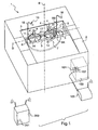
- the figure 1 is a general view of this reading device of form 1, as it is presented to its user.
- This apparatus comprises an upper cover 2 covering the entire apparatus except for a central upper portion.
- the shape reading apparatus 1 is intended to raise the shape of the bezels 11 of an eyeglass frame chosen by a wearer.
- the chosen eyeglass frame 10 is here of the rim type. It includes, as more specifically figures 1 and 2 two circles 14, namely a right circle and a left circle intended to be respectively positioned opposite the right eye and the left eye of the wearer when the latter carries said frame, and a trigger guard 17 linking the two circles 14 and two branches 18 each connected to one of the circles.
- the two circles each have an inner groove commonly called bezel 11 whose bottom forms a longitudinal strand.
- each of the circles of the selected spectacle frame 10 is adapted to receive an ophthalmic lens 15 provided on its edge with a bevel 16 intended to fit into one of the bezels 11.
- the shape reading apparatus 1 shown in the figure 1 has a set of two jaws 3 at least one of the jaws 3 is movable by relative to each other so that the jaws 3 can be moved toward or away from each other to form a clamping device.
- Each of the jaws 3 is further provided with two grippers each formed with two movable studs 4 to be adapted to clamp together the selected spectacle frame 10 in order to immobilize it.
- a frame 5 In the space left visible by the upper central opening of the cover 2, a frame 5 is visible.
- a plate (not visible) can move in translation on the frame 5 along a transfer axis D.
- On this plate is rotatably mounted a turntable 6.
- This turntable 6 is adapted to take two positions on the transfer axis D, a first position in which the center of the turntable 6 is disposed between the two pairs of studs 4 fixing the right circle of the chosen eyeglass frame 10, and a second position in which the center of the turntable 6 is disposed between the two pairs of studs 4 fixing the left circle of the selected spectacle frame 10.
- the turntable 6 has an axis of rotation B defined as the axis normal to the front face of the turntable 6 and passing through its center. It is adapted to pivot relative to the plate.
- the turntable 6 furthermore comprises an oblong slot 7 in the form of an arc of a circle through which a feeler 8 has a support rod 8A and, at its free end, a feeler finger 8B intended to follow by sliding or possibly rolling. the longitudinal strand of each bezel 11 of the selected spectacle frame 10.
- the shape reading apparatus 1 comprises actuating means (not shown) adapted, on the one hand, to slide the support rod 8A along the light 7 in order to move it away from or towards the center of the turntable 6, and, secondly, to position the feeler finger 8B of the probe 8 at a more or less high altitude relative to the plane of the front face of the turntable 6.
- the probe 8 is provided with three degrees of freedom, including a first degree of freedom TETA consisting of the ability of the probe 8 to pivot about the axis of rotation B by rotating the turntable 6 relative to the plate, a second degree of freedom Z constituted by the ability of the feeler 8 to translate along an axis parallel to the axis of rotation B of the turntable 6, and a third degree of freedom R constituted by the ability of the probe 8 to move relative to the axis of rotation B thanks to its freedom of movement along the arc formed by the light 7.
- a first degree of freedom TETA consisting of the ability of the probe 8 to pivot about the axis of rotation B by rotating the turntable 6 relative to the plate
- a second degree of freedom Z constituted by the ability of the feeler 8 to translate along an axis parallel to the axis of rotation B of the turntable 6
- a third degree of freedom R constituted by the ability of the probe 8 to move relative to the axis of rotation B thanks to its freedom of movement along the arc formed by the light 7.
- Each point read by the end of the feeler finger 8B of the probe 8 is located in a corresponding coordinate system R, TETA, Z.
- the shape reading apparatus 1 also comprises means 101 for acquiring the position R, TETA, Z of the end of the feeler finger 8B of the probe 8.
- control means 102 for actuating the apparatus, intended to control the position of the end of the feeler finger 8B of the probe 8.
- All of these acquisition means 101 and control 102 is integrated in an electronic device and / or computer 100 for, on the one hand, to actuate the actuating means of the device, and, on the other hand, on the other hand, to recover and record the data transmitted to it by sensors integrated in the shape reading device 1.
- This electronic and / or computer device 100 is furthermore connected to communication means 103, here wirelessly.
- These communication means 103 are adapted, on the one hand, to communicate with a lens-shaping machine (not shown) to transmit to it the results of read operations of the shapes of bezel drills, and on the other hand, to communicate with a computer server 200 remote from the reading device of form 1.
- This information server 200 comprises a register 201, each record of which is associated with a referenced category of one or more models of spectacle frames.
- each referenced category includes a single model of spectacle frames, so that each record is associated with a single model of spectacle frames.
- the identification field contains for example a unique identification code, such as a number or name, brand or reference, or an electronic tag signature (RFID, transponder, etc.).
- a unique identification code such as a number or name, brand or reference, or an electronic tag signature (RFID, transponder, etc.).
- the register contains a heading of longitudinal geometry which exerts a key function and merges with the identification field and constitutes a query key among the records of the register making it possible to retrieve, from data on the longitudinal geometry of the bezel of the mounting circle read by the shape reading apparatus, the corresponding recording.
- This section contains the cylindrical or other coordinates of a set of points of a remarkable longitudinal strand of the bezel such as the bezel bottom strand.
- the longitudinal geometry section may contain only approximate characteristics of the longitudinal geometry of the bezel of at least one of the circles of the mounting model concerned by the recording, allowing discrimination between the different models of mounts of the register. It is not necessary for the longitudinal geometry rubric to contain a complete description of the longitudinal geometry of the bezel allowing the trimming of a glass.
- the section of longitudinal geometry can thus contain the coordinates (cylindrical or other) of a set of 10 to 50 points of the bezel.
- the heading of longitudinal geometry contains more precise data on the longitudinal geometry of the bezel of the frame model concerned.
- Such a strengthening of the accuracy of the data provided in the longitudinal geometry section offers two main interests. On the one hand, it facilitates the implementation of search queries and avoids the appearance of duplicates by increased precision reinforcing the discriminating capacity of these data.
- it allows, as we shall see later, to recover, after a successful query made from short data on the longitudinal geometry of the bezel, the complete and precise data on this longitudinal geometry contained in the register and allowing the clipping of a lens.
- the heading of longitudinal geometry contains for this purpose the coordinates (cylindrical or other) of a set of at least 200 points of the bezel, typically between 300 and 1500 points.
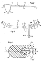
- the geometrical characteristics of the cross-sectional geometry heading comprise in this case three geometrical characteristics of the section of the bezel, measured in two sections S1, S2 separate from the bezel 11.
- One of the sections is located near the bridge 17 of the mount, and the other near the point of attachment of the branch 18 of the mount (corresponding for example to angular positions TETA of the probe 8 equal to 90 degrees and 270 degrees).
- These geometric characteristics consist of the aperture angle A of the bezel 11, the width at the opening D of the bezel 11, and its angle of inclination ALPHA with respect to a plane P parallel to the plane of the front face. turntable 6.
- the third geometric feature ALPHA makes it possible to take into account the inclination of the beetle due to the curve of the mount. It is also useful for predicting how the bevel 16 will fit into the bezel 11.
- these geometric features can be determined in a larger plurality of bezel sections to more accurately acquire the inclination of the bezel along the longitudinal strand.
- the geometric characteristics of the cross-sectional geometry item or sections furthermore comprise a fourth geometrical characteristic which is relative to the position of the bezel bottom 11 with respect to the front and / or rear edge of the spectacle frame, in a substantially perpendicular axial direction. to the plane of the mount or lens circle.
- This fourth geometrical characteristic then makes it possible to machine the lens so that its front and / or rear faces are located at a desired distance from the front and / or rear edges of the frame.
- the position of the top of the bevel is substantially identical to that of the bezel bottom. Consequently, by measuring the distance separating the bottom of the bezel and the front and / or rear edges of the frame, it is possible to position the front optical face of the lens with respect to the front edge of the corresponding circle of the frame by means of conventional steering of the position of the bevel on the edge of the lens.
- the optician In use, it is for the optician to acquire the shape data of a bezel of a chosen mount 10 sufficient to allow precise trimming of a lens to be mounted on the mount concerned. For this purpose, the optician proceeds first to the rapid acquisition of the longitudinal geometry of the bezel of the frame.
- the longitudinal strand is discretized into a number of points whose spatial coordinates corresponding to the coordinates R, TETA, Z of the end of the probe 8 when it is in contact with these points are to be recorded.
- the latter is inserted between the studs 4 of the jaws 3 so that each of the circles of the frame is ready to be palpated according to a starting path by inserting the feeler 8 between two studs 4 corresponding to the lower part of the frame, then following the bezel 11 of the frame, to cover the entire circumference of the circle 14 of the chosen eyeglass frame 10.
- the figure 3 represents the upper end of the probe 8, in particular its feeler finger 8B.
- the latter has a pointed end inserted in the bezel 11 of one of the circles 14 of the frame 10 to raise the shape of its longitudinal strand.
- the acquisition means 101 define as zero the angular position TETA, the altitude Z and the radial coordinate R of the end of the probe 8.
- the turntable 6 begins to rotate at a constant speed .
- the probe 8 moves along the bottom of the bezel 11 and is guided according to its radial coordinate R and according to its altitude Z by this bezel 11.
- the actuating means exert indeed an overall return force on the probe 8 which allows the probing finger 8B to remain in contact with the bottom of the bezel 11.
- the sensors of the reading device of shape 1 come up during the rotation of the turntable 6, the spatial coordinates of the points of the longitudinal strand of the bottom of the bezel 11.
- the apparatus can thus store a digital image of the two longitudinal strands of the funds of the beziers 11 of the circles 14 of the chosen eyeglass frame 10.
- the electronic and / or computer device 100 proceeds to a step of determining a model identifier. of the chosen eyeglass frame.
- the device develops a set of data characteristic of the acquired shape of the longitudinal strand.
- This dataset made from the acquired shape of the bezel is the identifier of the mount.
- This identifier is for example formed by the spatial coordinates (expressed for example in cylindrical coordinates: angle TETA, radius R and altitude Z of a plurality of points of the longitudinal strand distributed substantially uniformly along the bezel. a set of 10 to 50 points, preferably about thirty points.
- the electronic and / or computer device 100 communicates this identifier to the computer server 200 via its communication means 103.
- a search among the records of the register 201 of the computer server 200 is then performed in order to find a corresponding record whose identifier corresponds to the identifier of the eyeglass frame chosen 10.
- the electronic device and / or Computer 100 performs a search on the longitudinal geometry item or sections, which constitutes in this case the identification or key item as explained above.
- the search can for example be performed by the electronic device and / or computer 100 as follows.
- the data representative of the geometry of the longitudinal strand of the bezel bottom measured on the selected frame 10 (hereinafter “measured strand”) are stored by the electronic and / or computer device 100 which successively compares them with the data of the item or sections.
- measured strand The data representative of the geometry of the longitudinal strand of the bezel bottom measured on the selected frame 10
- registered strands are stored by the electronic and / or computer device 100 which successively compares them with the data of the item or sections.
- registered strands of longitudinal geometry relating to the geometry of the longitudinal strand of the bezel bottom of the models of frames of the register
- the electronic and / or computer device 100 makes a virtual matching of the recorded strand and the measured strand by means of an overlapping algorithm of these two strands.
- the recorded strand is defined by a set of N points whose coordinates are known in a defined frame.
- a set of M points of that strand is defined.
- the coordinates of these M points are then known in the defined coordinate system.
- the electronic and / or computer device 100 calculates the distances between the different points of the measured and recorded strands. In order to proceed to the "virtual" superimposition of these two strands, it determines the transformation that makes this superposition possible. It then applies, for example, to the registered strand this transformation and then obtains the transformed registered strand defined by the N transformed points of the registered strand.
- the number Nsup of points of the transformed strand transformed thus superimposed is greater than 90% of the number N, it is considered that the transformation is suitable and that the strands measured and recorded are superimposed.
- the transformation parameters are varied according to a determined range of values and using a sufficiently small increment, until a combination of these values provides a number of values. Nsup of points greater than 90% of the number N or the end of the register is reached without a recorded strand being superimposed on the measured strand.
- the threshold value of 90% can be modified according to the desired precision as well as the given distance defining the close neighborhood between two points.
- the mapping of the two strands can be performed by taking a limited number of points higher or lower.
- the electronic and / or computer device 100 deduces that the model to which the selected frame 10 belongs is absent from the register.
- this record is retained as corresponding to the model to which belongs the chosen mount 10.
- the electronic and / or computer device 100 reads from the register found the geometry data longitudinal (coordinates of at least 200 points of the longitudinal strand) of the bezel of the mount model corresponding to this record and therefore to which belongs the selected frame 10. The optician thus spares a precise reading, and therefore time consuming, of longitudinal strand of bezel.
- the electronic and / or computer device 100 also reads from the register register the geometrical characteristics A, D, ALPHA of the sections S1, S2 of the bezel 11 contained in the cross-sectional geometry section (s), as well as the axial distance between the bezel and the front and / or rear edge of the mount's circle, of the corresponding record.
- the electronic and / or computer device 100 displays a message suggesting to the operator that an accurate and complete measurement each circle of the selected frame 10 is made, to obtain the geometry data useful for trimming a lens to be mounted on the selected frame 10.
- the software starts a step of accurately measuring the longitudinal strand of the bezel bottom (on at least 200 points) and a probing step of the sections S1 and S2 of the bezel 11 of the spectacle frame chosen to determine the geometric characteristics A, D, ALPHA of these two sections of the bezel 11, as well as the front and / or rear edge of the mounting circle at this section. These geometric characteristics are then transferred to the device of clipping for the elaboration of the instructions of machining.
- the control means 102 of the probe 8 have the feeler finger 8B against the bezel 11 so that the angular position of its end is equal to 90 degrees - the probe 8 is thus in position to feel the first section S1 of the bezel 11 - Then, the actuating means drive the probe in translation so that it slides from one side to the other of the bezel 11, on each of its flanks and on each of its flanges.
- the acquisition means 101 of the electronic and computer system 100 raise the opening width D of the bezel 11 (generally between 1 and 2.5 millimeters) as well as the spatial coordinates of distinct points P1, P2, P3, P4 of each of the two sides of the bezel 11 to deduce the slope G1, G2 of these two flanks. They then calculate the opening angle A of the bezel 11 by summing the slope values G1, G2, as well as the ALPHA inclination angle of the bezel 11. They also calculate the distance separating the bottom of the bezel from each of the edges. front and back of the circle. The control means 102 then moves the probe 8 into a second position in which it is in contact with the bezel 11 and in which its angular position is equal to 270 degrees. The electronic and / or computer device 100 similarly deduces the width at the opening D, the opening angle A and the tilting angle ALPHA of the second section S2 of the bezel 11.
- the communication means 103 can then send the geometric characteristics A, D, ALPHA of the sections S1, S2 of the bezel 11 and the distances between the bezel and the front and / or rear edges of the circle of the frame 10, as well as the coordinates of the palpated points of the longitudinal strand of the bezel to the trimming machine so that the latter can calculate the form in which the ophthalmic lenses 15 will be cut off so that their respective bevel 16 can fit properly into the circles 14 of the frame selected glasses 10.
- a confirmation step of the fact that the selected frame 10 corresponds to the record found in the register 201 can be started. It consists in correlating all the coordinates of the 360 points taken from the longitudinal strand of the bezel 11 with all the data representative of the shape of the longitudinal strand of the recording found. If this correlation gives a positive result indicating that the shape of the palpated longitudinal strand corresponds to that of the longitudinal strand of the record found, the computer server 200 sends the set of geometric characteristics A, D, ALPHA of this record found to the reading apparatus of form 1. Otherwise, one proceeds to the probing sections S1, S2 of the bezel 11.
- the step of determining the model identifier of the selected eyeglass frame 10 is performed by means of a reading by the optician of identification means of the selected eyeglass frame.
- These identification means are for example constituted by an identification code written on a label attached to the frame. The optician having read this identification code, he enters it on the shape reading device, for example using a keyboard connected to the electronic device and / or computer 100, so that the latter can trigger the search for a matching record.
- the form reading apparatus 1 comprises optical reading means (not shown) of a bar code 13 carried by an identification plate 12 attached to one of the branches 18 of the chosen eyeglass frame 10.
- This code -barres 13 is the identifier of the model of the mount.
- the shape reading device 1 can automatically read the bar code 13 when the mount is installed in the device, in order to quickly and automatically search for the corresponding record in the register 201, which avoids the optician any additional load for the implementation of the method of acquisition of form according to the invention.
- the shape reading apparatus 1 comprises a reading antenna and the frames may be equipped with an RFID (Radio Frequency Identifier) type electronic tag or transponder.
- RFID Radio Frequency Identifier
- the information carried by the signal delivered by the transponder is then the identifier of the model of the spectacle frame.
- the search for a corresponding one of the register records can be performed manually.
- the shape reading apparatus 1 then comprises a man-machine interface such as a touch screen.
- the latter proposes to the operator to associate a bezel section to said mount.
- various icons representing various types of bezel sections are displayed on the touch screen.
- the operator at the only sight of the bezel of the eyeglass frame (or possibly after manually making a few measurements on the section of the bezel), then selects manually one of the icons so that the shape reading apparatus associates with said mount the selected bezel section.
- the trimming machine can then calculate the form in which the ophthalmic lenses to be mounted on this frame will be cut off so that their respective bevels can fit properly in the circles of the frame.
- each icon may include a mark and / or a mount name so that the operator easily selects in the register the record corresponding to the eyeglass frame installed in the shape reading apparatus.
Abstract
Description
La présente invention concerne de manière générale le domaine de la lunetterie et plus précisément l'acquisition de la forme d'un cercle d'une monture de lunettes du type cerclée.The present invention relates generally to the field of eyewear and more specifically to the acquisition of the shape of a circle of a spectacle frame rim type.
Elle concerne plus particulièrement un procédé d'acquisition de la forme d'une partie au moins d'une section d'un cercle d'une monture de lunettes choisie par un futur porteur, comprenant l'acquisition d'au moins une caractéristique géométrique de ladite section.It relates more particularly to a method of acquiring the shape of at least a portion of a section of a circle of an eyeglass frame chosen by a future carrier, comprising the acquisition of at least one geometrical characteristic of said section.
La partie technique du métier de l'opticien consiste à monter une paire de lentilles ophtalmiques sur une monture sélectionnée par un porteur. Ce montage se décompose en trois opérations principales :
- l'acquisition de la forme du drageoir de chacun des deux cercles de la monture de lunettes choisie par le futur porteur, c'est-à-dire de la forme du brin longitudinal du drageoir correspondant généralement au fond des rainures qui parcourent l'intérieur de chaque cercle de la monture, et éventuellement de la section du drageoir,
- le centrage de chaque lentille qui consiste à déterminer la position qu'occupera chaque lentille sur la monture afin d'être convenablement centrée en regard de la pupille de l'oeil du porteur de manière à ce qu'elle exerce convenablement la fonction optique pour laquelle elle a été conçue,
- le détourage de chaque lentille qui consiste à usiner ou à découper son contour à la forme souhaitée, compte tenu des paramètres de centrage définis, avec, en fin d'usinage, le biseautage qui consiste à réaliser sur la tranche de la lentille un biseau destiné à maintenir la lentille dans le drageoir que comporte la monture.
- the acquisition of the shape of the bezel of each of the two circles of the eyeglass frame chosen by the future wearer, that is to say the shape of the longitudinal strand of the bezel generally corresponding to the bottom of the grooves that run through the interior each circle of the frame, and possibly the section of the bezel,
- the centering of each lens which consists in determining the position that each lens will occupy on the frame in order to be properly centered facing the pupil of the wearer's eye so that it properly exercises the optical function for which it was designed,
- the trimming of each lens which consists of machining or cutting its contour to the desired shape, taking into account the defined centering parameters, with, at the end of machining, the beveling which consists in producing on the edge of the lens a bevel intended to maintain the lens in the bezel that includes the mount.
Dans le cadre de la présente invention, on s'intéresse notamment à la première opération d'acquisition de la forme des drageoirs des cercles de la monture de lunettes choisie.In the context of the present invention, it is particularly interested in the first operation of acquiring the shape of the bezels of the circles of the eyeglass frame chosen.
En pratique, il s'agit tout d'abord, pour l'opticien, de palper le contour intérieur de chacun des deux cercles de la monture de lunettes sélectionnée afin de déterminer précisément les coordonnées d'une pluralité de points caractérisant la forme du brin longitudinal du drageoir de chaque cercle. La connaissance de la forme de ce brin permet à l'opticien de déduire la forme que devra présenter le contour de la lentille correspondante, une fois détourée et biseautée, afin de pouvoir être insérée dans le cercle concerné de la monture.In practice, it is first of all, for the optician, palpate the inner contour of each of the two circles of the selected eyeglass frame to precisely determine the coordinates of a plurality of points characterizing the shape of the strand longitudinal of the bezel of each circle. The knowledge of the shape of this strand allows the optician to deduce the shape that must present the contour of the corresponding lens, once cut and bevelled, in order to can be inserted into the relevant circle of the mount.
L'objectif de cette opération est en particulier de suivre très exactement le fond du drageoir du cercle à lire, de manière à pouvoir mémoriser une image numérique précise de la forme du brin longitudinal du drageoir.The objective of this operation is in particular to follow exactly the bottom of the bezel of the circle to read, so as to memorize a precise digital image of the shape of the longitudinal strand of the bezel.
Pour améliorer la précision de l'emboitement de la lentille dans le cercle correspondant de la monture, l'opticien peut, comme l'exposent la demande de brevet
Généralement, toutes les sections d'un même drageoir présentent des géométries identiques ; cependant, l'opticien peut acquérir les formes de plusieurs sections du drageoir afin de prendre en compte l'inclinaison du drageoir due à la cambrure de la monture.Generally, all sections of the same bezel have identical geometries; however, the optician can acquire the shapes of several sections of the bezel to take into account the inclination of the bezel due to the camber of the frame.
L'inconvénient principal d'une telle opération de lecture de sections de drageoir est qu'elle est fastidieuse et longue à mettre en oeuvre pour l'opticien, en particulier s'il doit lire plusieurs sections d'un même drageoir.The main disadvantage of such a reading operation of bezel sections is that it is tedious and time consuming for the optician, especially if he has to read several sections of the same bezel.
Un autre objectif de cette opération d'acquisition des formes des drageoirs des cercles de la monture de lunettes choisie est de déterminer la position axiale optimale des lentilles par rapport aux bords avant ou arrière des cercles, de manière que le montage des lentilles sur la monture soit esthétique. En effet, par soucis d'esthétisme, on prévoit généralement de positionner les faces avant des lentilles à la hauteur des bords avant des cercles. En pratique, ce positionnement est réalisé en acquérant la position du fond du drageoir par rapport aux bords avant et/ou arrière des cercles de la monture, en au moins un point des cercles.Another objective of this operation of acquiring the shapes of the bezels of the circles of the eyeglass frame chosen is to determine the optimal axial position of the lenses with respect to the front or rear edges of the circles, so that the mounting of the lenses on the frame be aesthetic. Indeed, for the sake of aesthetics, it is generally expected to position the front faces of the lenses at the height of the front edges of the circles. In practice, this positioning is achieved by acquiring the position of the bottom of the bezel relative to the front and / or rear edges of the circles of the frame, at least one point of the circles.
Toutefois, ici également, cette opération est fastidieuse et longue à mettre en oeuvre.However, here too, this operation is tedious and time consuming to implement.
Afin notamment de remédier à l'inconvénient précité de l'état de la technique, on propose selon l'invention un procédé d'acquisition de la forme d'une section d'un cercle d'une monture de lunettes choisie selon la revendication 1.In particular in order to overcome the aforementioned drawback of the state of the art, it is proposed according to the invention a method of acquiring the shape of a section of a circle of a spectacle frame chosen according to
Ainsi, grâce à l'invention, lorsque la monture de lunettes choisie correspond à un modèle ou à une catégorie de modèles de montures de lunettes référencé dans le registre, l'étape de palpage de la section du drageoir est éludée au profit d'une étape très rapide de lecture dans le registre d'au moins une caractéristique géométrique de la section du drageoir. Cette simple étape de lecture permet ensuite de prévoir la manière selon laquelle le biseau de la lentille ophtalmique est destiné à s'emboîter dans le drageoir de la monture de lunettes choisie. Elle permet alors d'usiner en conséquence la tranche de la lentille. Cette étape de lecture peut en particulier permettre de récupérer la distance séparant le fond de drageoir et le bord avant de la monture en au moins un point des cercles. De cette manière, le biseau peut être positionné sur la tranche de la lentille de telle sorte que le bord avant et/ou arrière de la lentille soit situé, une fois la lentille montée dans son cercle, à une distance prédéterminée du bord avant de ce cercle.Thus, thanks to the invention, when the eyeglass frame chosen corresponds to a model or a category of glasses frame models referenced in the register, the probing step of the bezel section is evaded in favor of a very fast step of reading in the register of at least one geometrical characteristic of the section of the bezel. This simple reading step then makes it possible to predict the manner in which the bevel of the ophthalmic lens is intended to fit into the bezel of the chosen eyeglass frame. It then makes it possible to machine the slice of the lens accordingly. This reading step can in particular make it possible to recover the distance separating the bezel bottom and the front edge of the frame in at least one point of the circles. In this way, the bevel can be positioned on the edge of the lens so that the front and / or rear edge of the lens is located, once the lens is mounted in its circle, at a predetermined distance from the front edge of the lens. circle.
Le registre peut, dans un premier mode de réalisation, comporter des enregistrements associés chacun à un modèle défini de monture. En variante, le registre peut comporter des enregistrements associés chacun à une catégorie référencée de modèles de montures de lunettes. Il n'est alors pas forcément nécessaire que le modèle de la monture de lunettes choisie soit déjà connu ; il suffit que la catégorie à laquelle appartient le modèle de la monture choisie soit déterminée afin d'acquérir, si cette catégorie est référencée, la caractéristique géométrique de la section du drageoir. Plusieurs modèles de montures de lunettes réalisés par un même fabricant peuvent en effet présenter des géométries de sections de drageoirs identiques, si bien qu'il n'est pas utile de déterminer la forme de la section des drageoirs de chaque modèle de monture de la catégorie.The register may, in a first embodiment, include records each associated with a defined model mount. Alternatively, the register may include records each associated with a referenced category of spectacle frame models. It is not necessarily necessary that the model of the chosen eyeglass frame is already known; it is sufficient that the category to which belongs the model of the chosen mount is determined in order to acquire, if this category is referenced, the geometrical characteristic of the section of the bezel. Several models of eyeglass frames made by the same manufacturer may indeed have geometries of identical bezel sections, so it is not necessary to determine the shape of the section of the bevels of each frame model of the category .
Selon une première caractéristique avantageuse de l'invention, l'étape de lecture du registre est précédée d'une étape de détermination d'un identifiant d'un modèle ou d'une catégorie de modèles de montures de lunettes auquel appartient la monture de lunettes choisie, et, chaque enregistrement dudit registre comprenant au moins un identifiant du modèle ou de la catégorie de modèles auquel il est associé, la recherche d'un enregistrement correspondant est effectuée en recherchant un enregistrement dont l'identifiant correspond à l'identifiant déterminé du modèle ou de la catégorie de modèles de montures de lunettes à laquelle appartient la monture de lunettes choisie.According to a first advantageous characteristic of the invention, the step of reading the register is preceded by a step of determining an identifier. of a model or category of spectacle frame models to which the chosen eyeglass frame belongs, and, each record of said register comprising at least one identifier of the model or category of models with which it is associated, the search for a corresponding record is made by searching for a record whose identifier corresponds to the determined identifier of the model or the category of spectacle frame models to which belongs the chosen spectacle frame.
Ainsi, la recherche de la catégorie de la monture choisie est facilitée.Thus, the search for the category of the mount chosen is facilitated.
Préférentiellement, si aucun enregistrement correspondant n'est trouvé dans le registre, on procède à une étape de palpage, avec ou sans contact, d'au moins une section du cercle de la monture de lunettes choisie et on en déduit la caractéristique géométrique de section recherchée.Preferably, if no corresponding record is found in the register, a probing step, with or without contact, of at least one section of the circle of the chosen eyeglass frame is carried out and the geometric sectional characteristic is deduced therefrom. sought.
Le registre utilisé peut, soit être intégré à l'appareil de lecture effectuant le palpage des cercles de la monture choisie, soit être constitué par un registre central appartenant à un serveur informatique consultable par une pluralité d'opticiens. Une combinaison de ces deux solutions peut aussi être envisagée.The register used can either be integrated with the reading device probing the circles of the chosen frame, or be constituted by a central register belonging to a computer server that can be consulted by a plurality of opticians. A combination of these two solutions can also be considered.
S'il est intégré, il est rempli par l'opticien à chaque fois que ce dernier procède au palpage d'une section de drageoir d'une catégorie de modèles de montures que le registre n'a pas en mémoire, ce qui évite à l'opticien de palper plusieurs fois des sections de drageoirs de montures de lunettes d'une même catégorie de modèles.If it is integrated, it is filled by the optician each time the latter carries out the probing of a bezel section of a category of models of frames that the register does not have in memory, which avoids the optician to feel several times the sections of bezel frames of glasses of the same category of models.
Selon une caractéristique avantageuse de l'invention, l'étape de détermination de l'identifiant du modèle ou de la catégorie de modèles de montures de lunettes à laquelle appartient la monture choisie est réalisée par lecture, par un opérateur, d'un code d'identification de la monture de lunettes choisie.According to an advantageous characteristic of the invention, the step of determining the identifier of the model or of the category of spectacle frame models to which the chosen frame belongs is performed by reading, by an operator, a code of identification of the eyeglass frame chosen.
Ainsi, l'opticien peut-il lire l'identifiant du modèle ou de la catégorie de modèles de la monture choisie puis, soit rechercher dans un registre au format papier les caractéristiques de la forme de la section du drageoir qu'il recherche, soit recopier l'identifiant, par exemple par l'intermédiaire d'un clavier relié à un dispositif informatique, pour que ce dernier puisse lancer la recherche d'un enregistrement correspondant.Thus, the optician can read the identifier of the model or category of models of the selected frame and then, or search in a register in paper format characteristics of the shape of the section of the bezel he seeks, or copy the identifier, for example via a keyboard connected to a computer device, so that the latter can start searching for a corresponding record.
Selon une variante, l'étape de détermination de l'identifiant du modèle ou de la catégorie de modèles de montures de lunettes à laquelle appartient la monture choisie est réalisée par lecture de moyens d'identification équipant la monture de lunettes choisie. Avantageusement alors, les moyens d'identification de la monture de lunettes choisie comprennent un transpondeur ou un code-barres.According to one variant, the step of determining the identifier of the model or the category of spectacle frame models to which the selected frame belongs is performed by reading identification means equipping the chosen spectacle frame. Advantageously then, the identification means of the selected eyeglass frame comprise a transponder or a barcode.
Ainsi l'appareil réalisant la lecture de la forme du brin longitudinal peut-il lire automatiquement un code-barres d'une étiquette solidarisée à la monture afin de procéder rapidement et automatiquement à la recherche de l'enregistrement correspondant, ce qui évite à l'opticien toute charge supplémentaire pour la mise en oeuvre du procédé d'acquisition selon l'invention. L'appareil de lecture de forme peut également recevoir des ondes provenant du transpondeur solidaire de la monture, les traiter puis les lire afin de déterminer automatiquement l'identifiant du modèle ou de la catégorie de modèles auquel appartient la monture de lunettes choisie.Thus the device performing the reading of the shape of the longitudinal strand can it automatically read a barcode of a label secured to the mount to quickly and automatically search for the corresponding record, which avoids the optician any additional load for the implementation of the acquisition method according to the invention. The shape-reading apparatus may also receive waves from the transponder integral with the frame, process them and then read them to automatically determine the identifier of the model or category of models to which the chosen eyeglass frame belongs.
Selon une autre variante du procédé d'acquisition, on acquiert la forme d'un brin longitudinal d'un drageoir du cercle de la monture de lunettes choisie et on en déduit ledit identifiant du modèle ou de la catégorie de modèles de la monture choisie.According to another variant of the acquisition method, one acquires the shape of a longitudinal strand of a bezel of the circle of the chosen eyeglass frame and deduces said identifier of the model or category of models of the chosen frame.
Ainsi, l'identifiant de chaque monture peut-il être élaboré rapidement à partir des données acquises usuellement par l'opticien lors de la lecture de la forme du contour d'un drageoir, sans nécessiter aucune opération supplémentaire. Cet identifiant peut être constitué, par exemple, des coordonnées géométriques de certains points caractéristiques de la forme du brin longitudinal du drageoir.Thus, the identifier of each mount can be developed quickly from the data usually acquired by the optician when reading the shape of the outline of a bezel, without requiring any additional operation. This identifier may consist, for example, of the geometric coordinates of certain characteristic points of the shape of the longitudinal strand of the bezel.
Avantageusement alors, l'identifiant déterminé est un ensemble de données caractérisant ou représentant la forme du brin longitudinal du drageoir de la monture choisie et l'identifiant de chaque enregistrement du registre est un ensemble de données caractérisant ou représentant la forme du brin longitudinal du drageoir du modèle ou de la catégorie de modèles associé à l'enregistrement.Advantageously then, the determined identifier is a set of data characterizing or representing the shape of the longitudinal strand of the bezel of the chosen frame and the identifier of each record of the register is a set of data characterizing or representing the shape of the longitudinal strand of the bezel the model or category of models associated with the record.
Avantageusement, chaque enregistrement du registre est associé à un unique modèle de montures de lunettes.Advantageously, each record of the register is associated with a single model of spectacle frames.
Ainsi, les formes des sections des drageoirs des modèles de montures référencés, et en particulier leur inclinaison, peuvent être enregistrées dans le registre avec une précision accrue.Thus, the shapes of the bezel sections of the referenced frames, and in particular their inclination, can be recorded in the register with increased accuracy.
Avantageusement, ladite au moins une caractéristique géométrique de section du cercle comprend une caractéristique géométrique qui est relative à la forme d'un drageoir du cercle et/ou à une distance séparant le fond du drageoir de ce cercle et un bord avant ou arrière de ce cercle.Advantageously, said at least one geometric feature of section of the circle comprises a geometrical characteristic which is relative to the shape of a bezel of the circle and / or to a distance separating the bottom of the bezel from this circle and a front or rear edge of this circle. circle.
La description qui va suivre en regard des dessins annexés, donnés à titre d'exemples non limitatifs, fera bien comprendre en quoi consiste l'invention et comment elle peut être réalisée.The following description with reference to the accompanying drawings, given as non-limiting examples, will make it clear what the invention consists of and how it can be achieved.
Sur les dessins annexés :
- la
figure 1 est une vue schématique en perspective d'un appareil de lecture de forme selon l'invention accueillant une monture de lunettes ; - la
figure 2 est une vue schématique de côté de la monture de lunettes de lafigure 1 ; - la
figure 3 est une vue schématique en coupe des cercles de la monture de lunettes de lafigure 1 ; - les
figures 4 et5 sont des vues en coupe d'un palpeur de l'appareil de lecture de forme de lafigure 1 en contact du drageoir d'un des cercles de la monture de lunettes de lafigure 1 , cesfigures 4 et5 permettent de voir deux sections distinctes du drageoir ; et - la
figure 6 est une vue en coupe partielle d'une lentille ophtalmique emboîtée dans le drageoir d'un des cercles de la monture de lunettes de lafigure 1 .
- the
figure 1 is a schematic perspective view of a shape reading apparatus according to the invention accommodating a spectacle frame; - the
figure 2 is a schematic side view of the eyeglass frame of thefigure 1 ; - the
figure 3 is a schematic sectional view of the circles of the eyeglass frame of thefigure 1 ; - the
figures 4 and5 are sectional views of a probe of the shape reading device of thefigure 1 in contact with the bezel of one of the circles of the spectacle frame of thefigure 1 thesefigures 4 and5 allow to see two distinct sections of the bezel; and - the
figure 6 is a partial sectional view of an ophthalmic lens fitted into the bezel of one of the circles of the spectacle frame of thefigure 1 .
Pour la mise en oeuvre du procédé selon l'invention, il faut disposer d'un appareil de lecture de forme. Cet appareil de lecture de forme est un moyen bien connu de l'homme du métier et ne fait pas en propre l'objet de l'invention décrite. Il est par exemple possible d'utiliser un appareil de lecture de forme tel que décrit dans le
La
L'appareil de lecture de forme 1 est destiné à relever la forme des drageoirs 11 d'une monture de lunettes choisie par un porteur.The
La monture de lunettes choisie 10 est ici de type cerclé. Elle comporte, comme le montrent plus précisément les
L'appareil de lecture de forme 1 représenté sur la
Dans l'espace laissé visible par l'ouverture supérieure centrale du capot 2, un châssis 5 est visible. Une platine (non visible) peut se déplacer en translation sur ce châssis 5 selon un axe de transfert D. Sur cette platine est monté tournant un plateau tournant 6. Ce plateau tournant 6 est donc apte à prendre deux positions sur l'axe de transfert D, une première position dans laquelle le centre du plateau tournant 6 est disposé entre les deux paires de plots 4 fixant le cercle droit de la monture de lunettes choisie 10, et une seconde position dans laquelle le centre du plateau tournant 6 est disposé entre les deux paires de plots 4 fixant le cercle gauche de la monture de lunettes choisie 10.In the space left visible by the upper central opening of the
Le plateau tournant 6 possède un axe de rotation B défini comme l'axe normal à la face avant de ce plateau tournant 6 et passant par son centre. Il est adapté à pivoter par rapport à la platine. Le plateau tournant 6 comporte par ailleurs une lumière 7 oblongue en forme d'arc de cercle à travers laquelle saille un palpeur 8 comportant une tige support 8A et, à son extrémité libre, un doigt de palpage 8B destiné à suivre par glissement ou éventuellement roulement le brin longitudinal de chaque drageoir 11 de la monture de lunettes choisie 10.The
L'appareil de lecture de forme 1 comporte des moyens d'actionnement (non représentés) adaptés, d'une part, à faire glisser la tige support 8A le long de la lumière 7 afin de l'éloigner ou de la rapprocher du centre du plateau tournant 6, et, d'autre part, à positionner le doigt de palpage 8B du palpeur 8 à une altitude plus ou moins importante par rapport au plan de la face avant du plateau tournant 6.The
En résumé, le palpeur 8 est pourvu de trois degrés de liberté, dont un premier degré de liberté TETA constitué par l'aptitude du palpeur 8 à pivoter autour de l'axe de rotation B grâce à la rotation du plateau tournant 6 par rapport à la platine, un deuxième degré de liberté Z constitué par l'aptitude du palpeur 8 à se translater selon un axe parallèle à l'axe de rotation B du plateau tournant 6, et un troisième degré de liberté R constitué par l'aptitude du palpeur 8 à se mouvoir par rapport à l'axe de rotation B grâce à sa liberté de mouvement le long de l'arc de cercle formé par la lumière 7.In summary, the
Chaque point lu par l'extrémité du doigt de palpage 8B du palpeur 8 est repéré dans un système de coordonnées correspondant R, TETA, Z.Each point read by the end of the
L'appareil de lecture de forme 1 comporte par ailleurs des moyens d'acquisition 101 de la position R, TETA, Z de l'extrémité du doigt de palpage 8B du palpeur 8.The
Il comporte également des moyens de pilotage 102 des moyens d'actionnement de l'appareil, destinés à piloter la position de l'extrémité du doigt de palpage 8B du palpeur 8.It also comprises control means 102 for actuating the apparatus, intended to control the position of the end of the
L'ensemble de ces moyens d'acquisition 101 et de pilotage 102 est intégré dans un dispositif électronique et/ou informatique 100 permettant, d'une part, d'actionner les moyens d'actionnement de l'appareil, et, d'autre part, de récupérer et d'enregistrer les données que lui transmettent des capteurs intégrés à l'appareil de lecture de forme 1.All of these acquisition means 101 and control 102 is integrated in an electronic device and / or
Ce dispositif électronique et/ou informatique 100 est en outre relié à des moyens de communication 103, ici sans fil. Ces moyens de communication 103 sont adaptés, d'une part, à communiquer avec une machine de détourage de lentilles (non représentée) pour lui transmettre les résultats des opérations de lecture des formes de drageoirs lus, et d'autre part, à communiquer avec un serveur informatique 200 distant de l'appareil de lecture de forme 1.This electronic and / or
Ce serveur information 200 comporte un registre 201 dont chaque enregistrement est associé à une catégorie référencée de un ou plusieurs modèles de montures de lunettes. Ici, chaque catégorie référencée comporte un unique modèle de montures de lunettes, si bien que chaque enregistrement est associé à un unique modèle de montures de lunettes.This
Chaque enregistrement comprend plusieurs rubriques d'informations, dont :
- une ou plusieurs rubriques d'identification formant clef primaire, contenant un identifiant du modèle de montures de lunettes,
- une ou plusieurs rubriques de géométrie transversale contenant des caractéristiques géométriques de plusieurs sections des cercles (en particulier du drageoir) des montures ou de lunettes de ce modèle de montures
- une ou plusieurs rubriques de géométrie longitudinale contenant un ensemble de données représentatives de la géométrie (forme et dimensions) des brins longitudinaux des drageoirs des montures de lunettes de ce modèle de montures.
- one or more identification items forming a primary key, containing an identifier of the model of spectacle frames,
- one or more items of transverse geometry containing geometric characteristics of several sections of the circles (in particular the bezel) of the frames or glasses of this model of frames
- one or more items of longitudinal geometry containing a set of data representative of the geometry (shape and dimensions) of the longitudinal strands of the bezels of the spectacle frames of this model of frames.
Il est possible de prévoir que la rubrique d'identification soit distincte de la rubrique de géométrie longitudinale ou au contraire confondue avec cette dernière.It is possible to predict that the identification field is distinct from the longitudinal geometry section or, on the contrary, confused with it.
Lorsque ces rubriques sont distinctes, la rubrique d'identification contient par exemple un code d'identification unique, tel qu'un numéro ou un nom, marque ou référence, ou encore une signature d'étiquette électronique (RFID, transpondeur, etc.).When these items are distinct, the identification field contains for example a unique identification code, such as a number or name, brand or reference, or an electronic tag signature (RFID, transponder, etc.).
En l'espèce au contraire, le registre contient une rubrique de géométrie longitudinale qui exerce une fonction de clef et se confond avec la rubrique d'identification et constitue une clef de requête parmi les enregistrements du registre permettant de retrouver, à partir de données sur la géométrie longitudinale du drageoir du cercle de monture lu par l'appareil de lecture de forme, l'enregistrement correspondant. Cette rubrique contient les coordonnées cylindriques ou autres d'un ensemble de points d'un brin longitudinal remarquable du drageoir tel que le brin de fond de drageoir.In the present case, on the contrary, the register contains a heading of longitudinal geometry which exerts a key function and merges with the identification field and constitutes a query key among the records of the register making it possible to retrieve, from data on the longitudinal geometry of the bezel of the mounting circle read by the shape reading apparatus, the corresponding recording. This section contains the cylindrical or other coordinates of a set of points of a remarkable longitudinal strand of the bezel such as the bezel bottom strand.
Pour exercer sa fonction de clef, la rubrique de géométrie longitudinale peut contenir seulement des caractéristiques approximatives de la géométrie longitudinale du drageoir de l'un au moins des cercles du modèle de monture concerné par l'enregistrement, permettant une discrimination entre les différents modèles de montures du registre. Il n'est pas nécessaire que la rubrique de géométrie longitudinale contienne une description complète de la géométrie longitudinale du drageoir permettant de procéder au détourage d'un verre. La rubrique de géométrie longitudinale peut ainsi contenir les coordonnées (cylindriques ou autres) d'un ensemble de 10 à 50 points du drageoir.To perform its key function, the longitudinal geometry section may contain only approximate characteristics of the longitudinal geometry of the bezel of at least one of the circles of the mounting model concerned by the recording, allowing discrimination between the different models of mounts of the register. It is not necessary for the longitudinal geometry rubric to contain a complete description of the longitudinal geometry of the bezel allowing the trimming of a glass. The section of longitudinal geometry can thus contain the coordinates (cylindrical or other) of a set of 10 to 50 points of the bezel.
Il est cependant avantageux de prévoir, comme en l'espèce, que la rubrique de géométrie longitudinal contient des données plus précises sur la géométrie longitudinale du drageoir du modèle de monture concerné. Un tel renforcement de la précision des données fournies dans la rubrique de géométrie longitudinale offre deux intérêts principaux. D'une part, il facilite la mise en oeuvre des requêtes de recherche et évite l'apparition de doublons par une précision accrue renforçant la capacité discriminante de ces données. D'autre part, il permet comme nous le verrons par la suite, de récupérer, après une requête fructueuse effectuée à partir de données succinctes sur la géométrie longitudinale du drageoir, les données complètes et précises sur cette géométrie longitudinale contenue dans le registre et permettant le détourage d'une lentille. La rubrique de géométrie longitudinale contient à cet effet les coordonnées (cylindriques ou autres) d'un ensemble d'au moins 200 points du drageoir, typiquement entre 300 est 1500 points.However, it is advantageous to provide, as in this case, that the heading of longitudinal geometry contains more precise data on the longitudinal geometry of the bezel of the frame model concerned. Such a strengthening of the accuracy of the data provided in the longitudinal geometry section offers two main interests. On the one hand, it facilitates the implementation of search queries and avoids the appearance of duplicates by increased precision reinforcing the discriminating capacity of these data. On the other hand, it allows, as we shall see later, to recover, after a successful query made from short data on the longitudinal geometry of the bezel, the complete and precise data on this longitudinal geometry contained in the register and allowing the clipping of a lens. The heading of longitudinal geometry contains for this purpose the coordinates (cylindrical or other) of a set of at least 200 points of the bezel, typically between 300 and 1500 points.
Comme le montrent plus particulièrement les
Ces deux premières caractéristiques géométriques A, D du drageoir 11 permettent, comme le montre plus précisément la
En variante, on peut déterminer ces caractéristiques géométriques en une pluralité plus importante de sections du drageoir afin d'acquérir plus précisément l'inclinaison du drageoir le long du brin longitudinal.Alternatively, these geometric features can be determined in a larger plurality of bezel sections to more accurately acquire the inclination of the bezel along the longitudinal strand.
Les caractéristiques géométriques de la ou des rubriques de géométrie transversale comportent de plus une quatrième caractéristique géométrique qui est relative à la position du fond de drageoir 11 par rapport au bord avant et/ou arrière de la monture de lunettes, suivant une direction axiale sensiblement perpendiculaire au plan du cercle de monture ou de la lentille.The geometric characteristics of the cross-sectional geometry item or sections furthermore comprise a fourth geometrical characteristic which is relative to the position of the bezel bottom 11 with respect to the front and / or rear edge of the spectacle frame, in a substantially perpendicular axial direction. to the plane of the mount or lens circle.
Cette quatrième caractéristique géométrique permet ensuite d'usiner la lentille de manière que ses faces avant et/ou arrière soient situées à une distance voulue des bords avant et/ou arrière de la monture.This fourth geometrical characteristic then makes it possible to machine the lens so that its front and / or rear faces are located at a desired distance from the front and / or rear edges of the frame.
En effet, une fois le biseau de la lentille emboîté dans le drageoir de la monture, la position du sommet du biseau est sensiblement identique à celle du fond de drageoir. Par conséquent, en mesurant la distance séparant le fond du drageoir et les bords avant et/ou arrière de la monture, on peut positionner de manière esthétique la face optique avant de la lentille par rapport au bord avant du cercle correspondant de la monture au moyen d'un pilotage classique de la position du biseau sur la tranche de la lentille.Indeed, once the bevel of the lens fitted into the bezel of the frame, the position of the top of the bevel is substantially identical to that of the bezel bottom. Consequently, by measuring the distance separating the bottom of the bezel and the front and / or rear edges of the frame, it is possible to position the front optical face of the lens with respect to the front edge of the corresponding circle of the frame by means of conventional steering of the position of the bevel on the edge of the lens.
En pratique, on peut ainsi positionner la lentille sur la monture de manière que la distance séparant la face avant de la lentille et le bord avant du cercle soit sensiblement constante sur toute la périphérie de la lentille (par exemple nulle). On peut en variante obtenir un montage équilibré dans lequel la distance précitée est égale à la distance séparant la face arrière de la lentille et le bord arrière du cercle.In practice, it is thus possible to position the lens on the frame so that the distance separating the front face of the lens and the front edge of the circle is substantially constant over the entire periphery of the lens (for example zero). It is possible alternatively to obtain a balanced mounting in which the aforementioned distance is equal to the distance separating the rear face of the lens and the back edge of the circle.
Le registre 201 peut par ailleurs comporter des rubriques additionnelles contenant des informations supplémentaires, telles que :
- la marque du fabricant de la monture de lunettes 10,
- la base de cette monture (c'est-à-dire, en considérant que la monture s'étend selon la surface d'un cylindre, le rayon de ce cylindre),
- la matière plastique ou métallique de cette monture,
- la couleur de cette monture,
- l'angle pantoscopique de cette monture (c'est-à-dire l'angle formé entre le plan moyen des cercles de la monture et le plan qui est orthogonal aux branches de la monture lorsqu'elles sont déployées),
- la distance séparant les deux cercles de la monture,
- des informations relatives à des éléments décoratifs associés aux lentilles, comme par exemple les formes et positions par rapport à la monture de motifs destinés à être gravés sur les lentilles,
- des informations relatives aux positions et dimensions des trous de perçage des lentilles destinées à un montage avec des montures sans cercles.
- the mark of the maker of the
spectacle frame 10, - the base of this frame (that is to say, considering that the frame extends along the surface of a cylinder, the radius of this cylinder),
- the plastic or metal material of this frame,
- the color of this mount,
- the pantoscopic angle of this frame (that is to say the angle formed between the mean plane of the circles of the frame and the plane which is orthogonal to the branches of the frame when they are deployed),
- the distance between the two circles of the mount,
- information relating to decorative elements associated with the lenses, such as, for example, the shapes and positions relative to the frame of patterns intended to be etched on the lenses,
- information relating to the positions and dimensions of the drill holes of the lenses for mounting with frames without circles.
En service, il s'agit pour l'opticien d'acquérir les données de forme d'un drageoir d'une monture choisie 10 suffisantes pour permettre le détourage précis d'une lentille destinée à être montée sur la monture concernée. A cet effet, l'opticien procède d'abord à l'acquisition rapide de la géométrie longitudinale du drageoir de la monture.In use, it is for the optician to acquire the shape data of a bezel of a chosen
Pour cela, le brin longitudinal est discrétisé en un certain nombre de points dont on cherche à relever les coordonnées spatiales correspondant aux coordonnées R, TETA, Z de l'extrémité du palpeur 8 lorsque ce dernier est au contact de ces points.For this purpose, the longitudinal strand is discretized into a number of points whose spatial coordinates corresponding to the coordinates R, TETA, Z of the end of the
En référence à la
La
La conservation du contact du doigt de palpage 8B avec le fond du drageoir 11 est assurée par les moyens d'actionnement. Ces derniers exercent en effet un effort global de rappel sur le palpeur 8 qui permet au doigt de palpage 8B de rester en contact avec le fond du drageoir 11. Les capteurs de l'appareil de lecture de forme 1 relèvent pendant la rotation du plateau tournant 6 les coordonnées spatiales des points du brin longitudinal du fond du drageoir 11. L'appareil peut ainsi mémoriser une image numérique des deux brins longitudinaux des fonds des drageoirs 11 des cercles 14 de la monture de lunettes choisie 10.Preservation of the contact of the probing
A la suite de cette opération de palpage de la forme du brin longitudinal de chacun des drageoirs 11 des cercles 14 de la monture de lunettes choisie 10, le dispositif électronique et/ou informatique 100 procède à une étape de détermination d'un identifiant du modèle de la monture de lunettes choisie.Following this operation of probing the shape of the longitudinal strand of each of the
Pour ce faire, le dispositif élabore un jeu de données caractéristiques de la forme acquise du brin longitudinal. Ce jeu de données réalisé à partir de la forme acquise du drageoir constitue l'identifiant de la monture. Cet identifiant est par exemple formé par les coordonnées spatiales (exprimées par exemple en coordonnées cylindriques : angle TETA, rayon R et altitude Z d'une pluralité de points du brin longitudinal répartis de façon sensiblement régulière le long du drageoir. On peut par exemple utiliser un ensemble de 10 à 50 points, avantageusement d'une trentaine de points.To do this, the device develops a set of data characteristic of the acquired shape of the longitudinal strand. This dataset made from the acquired shape of the bezel is the identifier of the mount. This identifier is for example formed by the spatial coordinates (expressed for example in cylindrical coordinates: angle TETA, radius R and altitude Z of a plurality of points of the longitudinal strand distributed substantially uniformly along the bezel. a set of 10 to 50 points, preferably about thirty points.
L'identifiant ayant été ainsi déterminé, le dispositif électronique et/ou informatique 100 communique cet identifiant au serveur informatique 200 par l'intermédiaire de ses moyens de communication 103.The identifier having thus been determined, the electronic and / or
Une recherche parmi les enregistrements du registre 201 du serveur informatique 200 est alors effectuée dans le but de trouver un enregistrement correspondant dont l'identifiant correspond à l'identifiant de la monture de lunettes choisie 10. A cet effet, le dispositif électronique et/ou informatique 100 effectue une recherche sur la ou les rubriques de géométrie longitudinale, qui constitue en l'espèce la rubrique d'identification ou clef comme expliqué précédemment. La recherche peut par exemple être effectuée par le dispositif électronique et/ou informatique 100 de la façon suivante.A search among the records of the
Les données représentatives de la géométrie du brin longitudinal de fond de drageoir mesurées sur la monture choisie 10 (ci-après « brin mesuré ») sont mémorisées par le dispositif électronique et/ou informatique 100 qui les compare successivement aux données de la ou des rubriques de géométrie longitudinale relatives à la géométrie du brin longitudinal de fond de drageoir des modèles de montures du registre (ci-après « brins enregistrés »).The data representative of the geometry of the longitudinal strand of the bezel bottom measured on the selected frame 10 (hereinafter "measured strand") are stored by the electronic and / or
Pour chaque enregistrement, le dispositif électronique et/ou informatique 100 réalise une mise en correspondance virtuelle du brin enregistré et du brin mesuré au moyen d'un algorithme de superposition de ces deux brins.For each recording, the electronic and / or
Le brin enregistré est défini par un ensemble de N points dont les coordonnées sont connues dans un repère défini. De la même manière, lorsque l'appareil de lecture de forme 1 acquiert le brin mesuré, un ensemble de M points de ce brin est défini. Les coordonnées de ces M points sont alors connues dans le repère défini. Le dispositif électronique et/ou informatique 100 calcule les distances entres les différents points des brins mesuré et enregistré. Afin de procéder à la superposition "virtuelle" de ces deux brins, il détermine la transformation qui permet de réaliser cette superposition. Il applique alors par exemple au brin enregistré cette transformation et obtient alors le brin enregistré transformé défini par les N points transformés du brin enregistré.The recorded strand is defined by a set of N points whose coordinates are known in a defined frame. In the same way, when the
Puis, il compte le nombre Nsup de points parmi les N points du brin enregistré qui sont situés dans un proche voisinage d'un point du brin mesuré. Par "proche voisinage" on entend que les deux points concernés sont situés à une distance l'un de l'autre inférieure à une distance donnée, par exemple quelques dixièmes de millimètre. Chaque point du brin enregistré transformé situé dans un proche voisinage d'un des M points du brin mesuré, est considéré comme étant superposé à ce point.Then, it counts the number Nsup of points among the N points of the recorded strand which are located in a close neighborhood of a point of the measured strand. "Close neighborhood" means that the two points concerned are located at a distance from each other below a given distance, for example a few tenths of a millimeter. Each point of the transformed recorded strand located in a close vicinity of one of the M points of the measured strand, is considered to be superimposed at this point.
Si le nombre Nsup de points du brin enregistré transformé ainsi superposés est supérieur à 90% du nombre N, on considère que la transformation convient et que donc les brins mesuré et enregistré sont superposés. Par contre, si le nombre Nsup est inférieur ou égal à 90%, on fait varier les paramètres de transformation suivant une plage de valeurs déterminée et en utilisant un incrément suffisamment petit, jusqu'à ce qu'une combinaison de ces valeurs fournisse un nombre Nsup de points supérieur à 90% du nombre N ou que la fin du registre soit atteinte sans qu'un brin enregistré ne se superpose au brin mesuré.If the number Nsup of points of the transformed strand transformed thus superimposed is greater than 90% of the number N, it is considered that the transformation is suitable and that the strands measured and recorded are superimposed. On the other hand, if the number Nsup is less than or equal to 90%, the transformation parameters are varied according to a determined range of values and using a sufficiently small increment, until a combination of these values provides a number of values. Nsup of points greater than 90% of the number N or the end of the register is reached without a recorded strand being superimposed on the measured strand.
La valeur seuil de 90% peut être modifiée suivant la précision voulue de même que la distance donnée définissant le proche voisinage entre deux points. La mise en correspondance des deux brins peut être réalisée en prenant un nombre limité de points plus ou moins élevé.The threshold value of 90% can be modified according to the desired precision as well as the given distance defining the close neighborhood between two points. The mapping of the two strands can be performed by taking a limited number of points higher or lower.
Si aucun brin enregistré des différents enregistrements n'est trouvé, le dispositif électronique et/ou informatique 100 en déduit que le modèle auquel appartient la monture choisie 10 est absent du registre.If no recorded strand of the different recordings is found, the electronic and / or
Si un brin enregistré de l'un des enregistrements du registre est trouvé, cet enregistrement est retenu comme correspondant au modèle auquel appartient la monture choisie 10. Le dispositif électronique et/ou informatique 100 lit dans l'enregistrement trouvé du registre les données de géométrie longitudinale (coordonnées des 200 points au moins du brin longitudinal) du drageoir du modèle de monture correspondant à cet enregistrement et donc auquel appartient la monture choisie 10. L'opticien s'épargne ainsi une lecture précise, et par conséquent consommatrice de temps, du brin longitudinal de drageoir.If a registered strand of one of the records of the register is found, this record is retained as corresponding to the model to which belongs the chosen
Le dispositif électronique et/ou informatique 100 lit aussi dans l'enregistrement trouvé du registre les caractéristiques géométriques A, D, ALPHA des sections S1, S2 du drageoir 11 contenues dans la ou les rubriques de géométrie transversale, ainsi que la distance axiale entre le drageoir et le bord avant et/ou arrière du cercle de la monture, de l'enregistrement correspondant.The electronic and / or
Ces données de géométrie longitudinale et transversale sont transmises, via les moyens de communication 103 de l'appareil de lecture de forme 1, à la machine de détourage pour que cette dernière puisse calculer la forme selon laquelle les lentilles ophtalmiques 15 devront être détourées de manière à ce que leur biseau 16 puisse s'emboîter correctement et esthétiquement dans les cercles 14 de la monture de lunettes choisie 10.These data of longitudinal and transverse geometry are transmitted, via the communication means 103 of the
En revanche, si la recherche n'a pas été concluante et qu'aucun enregistrement correspondant n'a été trouvé dans le registre, le dispositif électronique et/ou informatique 100 affiche un message proposant à l'opérateur qu'une mesure précise et complète de chaque cercle de la monture choisie 10 soit effectuée, pour obtenir les données de géométrie utiles au détourage d'une lentille destinée à être montée sur la monture choisie 10. En cas de validation par l'opérateur ou à défaut de réponse de ce dernier à l'expiration d'un délai prédéfini, le logiciel lance une étape de mesure précise du brin longitudinal du fond de drageoir (sur au moins 200 points) et une étape de palpage des sections S1 et S2 du drageoir 11 de la monture de lunettes choisie 10 pour déterminer les caractéristiques géométriques A, D, ALPHA de ces deux sections du drageoir 11, ainsi que du bord avant et/ou arrière du cercle de monture au niveau de cette section. Ces caractéristiques géométriques sont ensuite transférées au dispositif de détourage pour l'élaboration des consignes d'usinage.On the other hand, if the search has not been conclusive and no corresponding record has been found in the register, the electronic and / or
Pour le palpage de la section du cercle de monture et en particulier du drageoir, comme le montrent les
Les moyens de communication 103 peuvent alors envoyer les caractéristiques géométriques A, D, ALPHA des sections S1, S2 du drageoir 11 et les distances entre le drageoir et les bords avant et/ou arrière du cercle de la monture 10, ainsi que les coordonnées des points palpés du brin longitudinal du drageoir à la machine de détourage pour que cette dernière puisse calculer la forme selon laquelle les lentilles ophtalmiques 15 devront être détourées de manière à ce que leur biseau 16 respectif puisse s'emboîter correctement dans les cercles 14 de la monture de lunettes choisie 10.The communication means 103 can then send the geometric characteristics A, D, ALPHA of the sections S1, S2 of the
Selon une variante de réalisation de l'invention, lorsque la recherche d'un enregistrement correspondant semble fructueuse, une étape de confirmation du fait que la monture choisie 10 correspond bien à l'enregistrement trouvé dans le registre 201 peut être lancée. Elle consiste à corréler l'ensemble des coordonnées des 360 points relevés du brin longitudinal du drageoir 11 avec l'ensemble des données représentatives de la forme du brin longitudinal de l'enregistrement trouvé. Si cette corrélation fournit un résultat positif indiquant que la forme du brin longitudinal palpé correspond bien à celle du brin longitudinal de l'enregistrement trouvé, le serveur informatique 200 envoie l'ensemble des caractéristiques géométriques A, D, ALPHA de cet enregistrement trouvé à l'appareil de lecture de forme 1. Sinon, on procède au palpage des sections S1, S2 du drageoir 11.According to an alternative embodiment of the invention, when the search for a corresponding record seems successful, a confirmation step of the fact that the selected
Selon un autre mode de réalisation, l'étape de détermination de l'identifiant du modèle de la monture de lunettes choisie 10 est réalisée au moyen d'une lecture, par l'opticien, de moyens d'identification de la monture de lunettes choisie. Ces moyens d'identification sont par exemple constitués par un code d'identification écrit sur une étiquette fixée à la monture. L'opticien ayant lu ce code d'identification, il le saisit sur l'appareil de lecture de forme, par exemple à l'aide d'un clavier relié au dispositif électronique et/ou informatique 100, pour que ce dernier puisse déclencher la recherche d'un enregistrement correspondant.According to another embodiment, the step of determining the model identifier of the selected
Selon un autre mode de réalisation représenté sur la
Ainsi l'appareil de lecture de forme 1 peut-il lire automatiquement le code-barres 13 lorsque la monture est installée dans l'appareil, afin de procéder rapidement et automatiquement à la recherche de l'enregistrement correspondant dans le registre 201, ce qui évite à l'opticien toute charge supplémentaire pour la mise en oeuvre du procédé d'acquisition de forme selon l'invention.Thus, the
Selon une variante de ce mode de réalisation, l'appareil de lecture de forme 1 comporte une antenne de lecture et les montures peuvent être équipées d'une étiquette électronique du type RFID (Radio Frequence Identifier) ou transpondeur. L'information portée par le signal délivré par le transpondeur constitue alors l'identifiant du modèle de la monture de lunettes.According to a variant of this embodiment, the
Selon un autre mode de réalisation de l'invention, la recherche d'un enregistrement correspondant parmi les enregistrements du registre peut être effectuée manuellement. L'appareil de lecture de forme 1 comporte alors une interface homme-machine telle qu'un écran tactile.According to another embodiment of the invention, the search for a corresponding one of the register records can be performed manually. The
Selon ce mode de réalisation, à la suite de la lecture de la forme du contour du drageoir de la monture de lunettes installée dans l'appareil de lecture de forme, ce dernier propose à l'opérateur d'associer une section de drageoir à ladite monture. Dans ce dessein, diverses icônes représentant divers types de sections de drageoirs s'affichent sur l'écran tactile. L'opérateur, à la seule vue du drageoir de la monture de lunettes (ou éventuellement après avoir réalisé manuellement quelques mesures sur la section du drageoir), sélectionne alors manuellement une des icônes de manière à ce que l'appareil de lecture de forme associe à ladite monture la section de drageoir sélectionnée.According to this embodiment, following the reading of the shape of the outline of the bezel of the eyeglass frame installed in the shape reading device, the latter proposes to the operator to associate a bezel section to said mount. For this purpose, various icons representing various types of bezel sections are displayed on the touch screen. The operator, at the only sight of the bezel of the eyeglass frame (or possibly after manually making a few measurements on the section of the bezel), then selects manually one of the icons so that the shape reading apparatus associates with said mount the selected bezel section.
Ainsi, la machine de détourage peut ensuite calculer la forme selon laquelle les lentilles ophtalmiques à monter sur cette monture devront être détourées de manière à ce que leurs biseaux respectifs puissent s'emboîter correctement dans les cercles de la monture.Thus, the trimming machine can then calculate the form in which the ophthalmic lenses to be mounted on this frame will be cut off so that their respective bevels can fit properly in the circles of the frame.
En variante chaque icône peut comporter une marque et/ou un nom de monture de telle sorte que l'opérateur sélectionne facilement dans le registre l'enregistrement correspondant à la monture de lunettes installée dans l'appareil de lecture de forme.Alternatively each icon may include a mark and / or a mount name so that the operator easily selects in the register the record corresponding to the eyeglass frame installed in the shape reading apparatus.
Claims (11)
- A method of acquiring the shape of at least a portion of a rim (14) of a selected eyeglass frame (10), the method comprising acquiring at least one geometrical characteristic (A, D, ALPHA) of a section of said rim (14), the method being characterized in that the acquisition of said at least one geometrical characteristic (A, D, ALPHA) comprises:- a step of acquiring the shape of a longitudinal strand of a bezel (11) of said rim (14)with a shape tracer appliance,- a step of reading a register (201) in which each entry is associated with an eyeglass frame model or category of models and includes at least one geometrical characteristic (A, D, ALPHA) of at least one section of a frame rim of said model or said category of models, with a search for an entry corresponding to the eyeglass frame model or category of models to which the selected eyeglass frame (10) belongs; and- a step of reading said at least one geometrical characteristic (A, D, ALPHA) from said corresponding entry, if a corresponding entry is found in the register (201).
- A method according to the preceding claim, in which the step of reading the register (201) is preceded by a step of determining an identifier (13) of an eyeglass frame model or category of models to which the selected eyeglass frame (10) belongs, with each entry of said register (201) including at least one identifier (13) of the model or category of models with which it is associated, and the search for a corresponding entry is performed by searching for an entry in which the identifier (13) corresponds to the determined identifier of the eyeglass frame model or category of models to which the selected eyeglass frame (10) belongs.
- A method according to any preceding claim, in which, if no corresponding entry is found in the register (201), a step is performed of feeling, with or without contact, at least one section of the bezel (11) of the rim (14) of the selected eyeglass frame (10), and the looked-for section geometrical characteristic is deduced therefrom.
- A method according to claim 2, in which the step of determining the identifier (13) of the eyeglass frame model or category of models to which the selected eyeglass frame (10) belongs is performed by reading identification means (12) fitted to the selected eyeglass frame (10).
- A method according to the preceding claim, in which the identification means (12) of the selected eyeglass frame (10) comprise a transponder or a bar code (13).
- A method according to claim 2, in which the step of determining the identifier (13) of the eyeglass frame model or category of models to which the selected eyeglass frame (10) belongs is performed by an operator reading an identification code (13) of the selected eyeglass frame (10).
- A method according to claim 2, in which said identifier of the model or the category of models of the selected frame is deduced from the shape of the longitudinal strand of the bezel (11).
- A method according to the preceding claim, in which the determined identifier is a data set characterizing or representing the shape of the longitudinal strand of the bezel (11) of the selected eyeglass frame (10), and the identifier of each entry in the register (201) is a data set characterizing or representing the shape of the longitudinal strand of the bezel of the model or category of models associated with the entry.
- A method according to any preceding claim, in which each entry in the register (201) is associated with a single eyeglass frame model.
- A method according to any preceding claim, in which said at least one geometrical characteristic (A, D, ALPHA) for the section of the rim (14) comprises a geometrical characteristic (A, D, ALPHA) relating to the shape of a bezel (11) of the rim (14).
- A method according to any preceding claim, in which said at least one geometrical characteristic (A, D, ALPHA) for the section of the rim (14) comprises a geometrical characteristic (A, D, ALPHA) relating to a distance between the bottom of a bezel (11) of said rim (14) and an edge of said rim.
Applications Claiming Priority (2)
| Application Number | Priority Date | Filing Date | Title |
|---|---|---|---|
| FR0604025 | 2006-05-05 | ||
| PCT/FR2007/000694 WO2007128902A1 (en) | 2006-05-05 | 2007-04-24 | Method of acquiring of at least a portion of the shape of a section of a spectacle frame circle |
Publications (2)
| Publication Number | Publication Date |
|---|---|
| EP2016365A1 EP2016365A1 (en) | 2009-01-21 |
| EP2016365B1 true EP2016365B1 (en) | 2011-09-28 |
Family
ID=37520625
Family Applications (1)
| Application Number | Title | Priority Date | Filing Date |
|---|---|---|---|
| EP07731353A Active EP2016365B1 (en) | 2006-05-05 | 2007-04-24 | Method of acquiring of at least a portion of the shape of a section of a spectacle frame circle |
Country Status (3)
| Country | Link |
|---|---|
| US (2) | US8215772B2 (en) |
| EP (1) | EP2016365B1 (en) |
| WO (1) | WO2007128902A1 (en) |
Families Citing this family (11)
| Publication number | Priority date | Publication date | Assignee | Title |
|---|---|---|---|---|
| FR2893723B1 (en) * | 2005-11-23 | 2008-02-01 | Essilor Int | SCREEN READING APPARATUS FOR EYEGLASS MOUNT CIRCUIT DRAGER |
| FR2910136B1 (en) * | 2006-12-18 | 2009-02-27 | Essilor Int | METHOD FOR CORRECTING THE GEOMETRY OF A SPINNING LAYER APPROACHING A LONGITUDINAL STRAND OF A GOGGLE MOUNT DRAWER AND METHOD OF ACQUIRING THE GEOMETRY OF A CONTOUR OF SUCH A DRAWER |
| JP4920514B2 (en) * | 2007-07-04 | 2012-04-18 | 株式会社ニデック | Ball shape measuring device |
| ES2353983T3 (en) | 2007-12-28 | 2011-03-08 | Essilor International (Compagnie Generale D'optique) | DETERMINATION PROCEDURE FOR APPLICATION PARAMETERS TO THE MOUNT OF AN OPHTHALMIC LENS. |
| FR2930050B1 (en) * | 2008-04-14 | 2010-09-24 | Essilor Int | APPARATUS FOR READING THE GEOMETRY OF A CIRCLE OR ARCADE OF EYEGLASS MOUNT AND READING METHOD THEREOF |
| JP2009300427A (en) * | 2008-05-14 | 2009-12-24 | Topcon Corp | Apparatus and method for measuring shape of eyeglass element |
| DE102010010340B4 (en) * | 2010-03-04 | 2013-11-28 | Schneider Gmbh & Co. Kg | Measuring arrangement for measuring a spectacle frame |
| CN105976148B (en) | 2010-03-15 | 2021-01-05 | 杜比实验室特许公司 | 3D glasses and related systems |
| US8348161B2 (en) * | 2011-01-14 | 2013-01-08 | Vincent Huang | Three-dimensional spectacles and a management system therefore |
| JP6641856B2 (en) * | 2015-10-05 | 2020-02-05 | 株式会社ニデック | Measurement jig |
| EP4166275A1 (en) * | 2021-10-18 | 2023-04-19 | Essilor International | Method for determining the shape of an eyeglass frame rim bezel |
Family Cites Families (6)
| Publication number | Priority date | Publication date | Assignee | Title |
|---|---|---|---|---|
| JPH0915540A (en) * | 1995-06-29 | 1997-01-17 | Washi Kosan Kk | Lens for right and left interchange type spectacles and spectacles using this lens |
| FR2751433B1 (en) | 1996-07-18 | 1998-10-09 | Essilor Int | PROCESS FOR TAKING UP THE CROWNING SECTION OF A GLASSES FRAME, CORRESPONDING SENSOR, AND APPLICATION OF THIS PROCESS TO OVERFLOWING THE MOUNTING GLASS |
| JP3276866B2 (en) | 1996-12-27 | 2002-04-22 | ホーヤ株式会社 | Eyeglass processing method and eyeglass frame |
| CN1105980C (en) * | 1998-02-03 | 2003-04-16 | 西乡刚 | Simulation system for wearing glasses |
| DE19804542C5 (en) * | 1998-02-05 | 2009-04-30 | Wernicke & Co Gmbh | Method and device for processing spectacle lenses |
| EP1092502B1 (en) | 1999-10-15 | 2005-08-17 | Kabushiki Kaisha TOPCON | Lens shape data processing apparatus and lens grinding machine having the same apparatus |
-
2007
- 2007-04-24 WO PCT/FR2007/000694 patent/WO2007128902A1/en active Application Filing
- 2007-04-24 US US12/297,923 patent/US8215772B2/en active Active
- 2007-04-24 EP EP07731353A patent/EP2016365B1/en active Active
-
2008
- 2008-04-14 US US12/596,773 patent/US8132909B2/en active Active
Also Published As
| Publication number | Publication date |
|---|---|
| US20090140036A1 (en) | 2009-06-04 |
| US8132909B2 (en) | 2012-03-13 |
| WO2007128902A1 (en) | 2007-11-15 |
| US8215772B2 (en) | 2012-07-10 |
| US20100134756A1 (en) | 2010-06-03 |
| EP2016365A1 (en) | 2009-01-21 |
Similar Documents
| Publication | Publication Date | Title |
|---|---|---|
| EP2016365B1 (en) | Method of acquiring of at least a portion of the shape of a section of a spectacle frame circle | |
| EP1817562B1 (en) | Device for automatically measuring characteristics of an ophthalmic lens | |
| EP1827757B1 (en) | Method and device for mounting preparation for a job of two ophthalmic lenses for the same pair of glasses | |
| EP2786202B1 (en) | Process of preparation of an ophthalmic lens | |
| FR2900246A1 (en) | METHOD FOR DETECTING AN OPTICAL REFERENTIAL OF AN OPHTHALMIC LENS | |
| EP2092268B1 (en) | Method for correcting the geometry of a probed curve | |
| EP2027968B1 (en) | Method of determining parameters for adding frames to an ophthalmic lens | |
| EP2210703B1 (en) | Eyeglass lens processing apparatus | |
| CA2956030A1 (en) | Method for working out settings for edging an optical lens | |
| EP2150375B1 (en) | Method for trimming ophthalmic lenses by reading out and updating a lens and/or frame database register | |
| EP2196845B1 (en) | Method for preparing an ophthalmic lens in order to mount it on a curved spectacle frame | |
| EP2268997B1 (en) | Apparatus and method for acquiring the shape of a spectacle frame circle or arcade | |
| FR2907041A1 (en) | METHOD FOR DISTRESSING AN OPHTHALMIC LENS | |
| EP2234758B9 (en) | Method for preparing an ophthalmic lens with specific machining of the fitting rib thereof | |
| EP1996368B9 (en) | Method of controlling a probe for reading the groove in a spectacle frame rim and corresponding reading apparatus | |
| WO2007065984A1 (en) | Method for generating setpoint radii for trimming an ophthalmic lens | |
| EP3172011A1 (en) | Machine for acquiring images of optical lenses and process for trimming optical lenses | |
| EP2160270B1 (en) | Methods for the automatic detection of the material of a spectacle frame, reading the shape of a frame, and edging lenses belonging to a frame |
Legal Events
| Date | Code | Title | Description |
|---|---|---|---|
| PUAI | Public reference made under article 153(3) epc to a published international application that has entered the european phase |
Free format text: ORIGINAL CODE: 0009012 |
|
| 17P | Request for examination filed |
Effective date: 20081105 |
|
| AK | Designated contracting states |
Kind code of ref document: A1 Designated state(s): AT BE BG CH CY CZ DE DK EE ES FI FR GB GR HU IE IS IT LI LT LU LV MC MT NL PL PT RO SE SI SK TR |
|
| AX | Request for extension of the european patent |
Extension state: AL BA HR MK RS |
|
| DAX | Request for extension of the european patent (deleted) | ||
| RBV | Designated contracting states (corrected) |
Designated state(s): DE ES FR GB IT |
|
| 17Q | First examination report despatched |
Effective date: 20100217 |
|
| GRAP | Despatch of communication of intention to grant a patent |
Free format text: ORIGINAL CODE: EPIDOSNIGR1 |
|
| GRAS | Grant fee paid |
Free format text: ORIGINAL CODE: EPIDOSNIGR3 |
|
| GRAA | (expected) grant |
Free format text: ORIGINAL CODE: 0009210 |
|
| AK | Designated contracting states |
Kind code of ref document: B1 Designated state(s): DE ES FR GB IT |
|
| REG | Reference to a national code |
Ref country code: GB Ref legal event code: FG4D Free format text: NOT ENGLISH |
|
| REG | Reference to a national code |
Ref country code: DE Ref legal event code: R081 Ref document number: 602007017518 Country of ref document: DE Owner name: ESSILOR INTERNATIONAL, FR Free format text: FORMER OWNER: ESSILOR INTERNATIONAL (COMPAGNIE GENERALE D'OPTIQUE), CHARENTON LE PONT, FR |
|
| REG | Reference to a national code |
Ref country code: DE Ref legal event code: R096 Ref document number: 602007017518 Country of ref document: DE Effective date: 20111201 |
|
| PG25 | Lapsed in a contracting state [announced via postgrant information from national office to epo] |
Ref country code: IT Free format text: LAPSE BECAUSE OF FAILURE TO SUBMIT A TRANSLATION OF THE DESCRIPTION OR TO PAY THE FEE WITHIN THE PRESCRIBED TIME-LIMIT Effective date: 20110928 |
|
| PLBE | No opposition filed within time limit |
Free format text: ORIGINAL CODE: 0009261 |
|
| STAA | Information on the status of an ep patent application or granted ep patent |
Free format text: STATUS: NO OPPOSITION FILED WITHIN TIME LIMIT |
|
| 26N | No opposition filed |
Effective date: 20120629 |
|
| REG | Reference to a national code |
Ref country code: DE Ref legal event code: R097 Ref document number: 602007017518 Country of ref document: DE Effective date: 20120629 |
|
| PG25 | Lapsed in a contracting state [announced via postgrant information from national office to epo] |
Ref country code: ES Free format text: LAPSE BECAUSE OF FAILURE TO SUBMIT A TRANSLATION OF THE DESCRIPTION OR TO PAY THE FEE WITHIN THE PRESCRIBED TIME-LIMIT Effective date: 20120108 |
|
| REG | Reference to a national code |
Ref country code: FR Ref legal event code: PLFP Year of fee payment: 10 |
|
| REG | Reference to a national code |
Ref country code: FR Ref legal event code: PLFP Year of fee payment: 11 |
|
| REG | Reference to a national code |
Ref country code: DE Ref legal event code: R082 Ref document number: 602007017518 Country of ref document: DE Representative=s name: 24IP LAW GROUP SONNENBERG FORTMANN, DE Ref country code: DE Ref legal event code: R081 Ref document number: 602007017518 Country of ref document: DE Owner name: ESSILOR INTERNATIONAL, FR Free format text: FORMER OWNER: ESSILOR INTERNATIONAL (COMPAGNIE GENERALE D'OPTIQUE), CHARENTON LE PONT, FR |
|
| REG | Reference to a national code |
Ref country code: FR Ref legal event code: PLFP Year of fee payment: 12 |
|
| REG | Reference to a national code |
Ref country code: GB Ref legal event code: 732E Free format text: REGISTERED BETWEEN 20180517 AND 20180523 |
|
| REG | Reference to a national code |
Ref country code: FR Ref legal event code: TP Owner name: ESSILOR INTERNATIONAL, FR Effective date: 20180601 |
|
| P01 | Opt-out of the competence of the unified patent court (upc) registered |
Effective date: 20230525 |
|
| PGFP | Annual fee paid to national office [announced via postgrant information from national office to epo] |
Ref country code: FR Payment date: 20230425 Year of fee payment: 17 Ref country code: DE Payment date: 20230427 Year of fee payment: 17 |
|
| PGFP | Annual fee paid to national office [announced via postgrant information from national office to epo] |
Ref country code: GB Payment date: 20230427 Year of fee payment: 17 |
|
| REG | Reference to a national code |
Ref country code: DE Ref legal event code: R082 Ref document number: 602007017518 Country of ref document: DE Representative=s name: SONNENBERG HARRISON PARTNERSCHAFT MBB PATENT- , DE |