EP2016336B1 - Vorrichtung zur messung der flammenintensität - Google Patents
Vorrichtung zur messung der flammenintensität Download PDFInfo
- Publication number
- EP2016336B1 EP2016336B1 EP06756288.4A EP06756288A EP2016336B1 EP 2016336 B1 EP2016336 B1 EP 2016336B1 EP 06756288 A EP06756288 A EP 06756288A EP 2016336 B1 EP2016336 B1 EP 2016336B1
- Authority
- EP
- European Patent Office
- Prior art keywords
- transistor
- flame intensity
- duty cycle
- signal
- measuring
- Prior art date
- Legal status (The legal status is an assumption and is not a legal conclusion. Google has not performed a legal analysis and makes no representation as to the accuracy of the status listed.)
- Expired - Lifetime
Links
Images



Classifications
-
- F—MECHANICAL ENGINEERING; LIGHTING; HEATING; WEAPONS; BLASTING
- F23—COMBUSTION APPARATUS; COMBUSTION PROCESSES
- F23N—REGULATING OR CONTROLLING COMBUSTION
- F23N5/00—Systems for controlling combustion
- F23N5/02—Systems for controlling combustion using devices responsive to thermal changes or to thermal expansion of a medium
- F23N5/12—Systems for controlling combustion using devices responsive to thermal changes or to thermal expansion of a medium using ionisation-sensitive elements, i.e. flame rods
- F23N5/123—Systems for controlling combustion using devices responsive to thermal changes or to thermal expansion of a medium using ionisation-sensitive elements, i.e. flame rods using electronic means
-
- F—MECHANICAL ENGINEERING; LIGHTING; HEATING; WEAPONS; BLASTING
- F23—COMBUSTION APPARATUS; COMBUSTION PROCESSES
- F23N—REGULATING OR CONTROLLING COMBUSTION
- F23N2223/00—Signal processing; Details thereof
- F23N2223/08—Microprocessor; Microcomputer
Definitions
- the present invention relates to a device for measuring flame intensity having the characteristic features set out in the preamble of the main claim.
- a device for measuring flame intensity having the characteristic features set out in the preamble of the main claim.
- Such a device is disclosed in GB 2 367 172 A .
- the invention is applied in particular, but not exclusively, in the sector of systems for the control of the gas supply to burners of appliances for heating in general, whose flame is adapted to heat the environment or an intermediate fluid circulating in a boiler plant.
- a typical application is in systems controlling the gas supply to burners of boilers for domestic heating and/or heating of domestic hot water.
- these devices are substantially invariable with respect to temperature variations, at least in the temperature range in which the device is used, to the dispersion of the properties of components and to variations in the supply voltage, without production costs and times and design complexity being greatly affected.
- a main object of the present invention is to provide a device for measuring flame intensity which is structurally and functionally adapted to satisfy the above-mentioned requirements and at the same time to remedy the drawbacks described with reference to the cited prior art.
- a device for measuring flame intensity adapted for instance to measure the flame intensity within burners, in accordance with the present invention, is shown overall by 1.
- the device for measuring flame intensity 1 comprises a flame sensor U1 disposed within the burner so as to come into contact with the flame when the latter is present, and to generate an ionisation current proportional to the intensity of this flame.
- the sensor U1 is preferably produced using conventional techniques in the sector and comprises, for instance, two electrodes.
- the operation of the flame sensor may be compared with that of a current generator connected to a one-way member, for instance a diode in series with a resistor (see diode D2 and resistor R10 in Fig 1 ): the current generated by the sensor as a result of the presence of the flame in practice flows in only one direction.
- a current generator connected to a one-way member, for instance a diode in series with a resistor (see diode D2 and resistor R10 in Fig 1 ): the current generated by the sensor as a result of the presence of the flame in practice flows in only one direction.
- the burner is often connected to earth in boilers embodied according to the prior art, with the result that when current is flowing in the sensor U1 as a result of the presence of a flame, this current "drains" towards earth.
- the currents generated by flame sensors coupled to known burners in the sector are of the order of microamperes.
- the ionisation current generated in the sensor U1 preferably varies within a range of 0.8 ⁇ A to 7.5 ⁇ A.
- the device of the invention may nevertheless also be used in the case of ionisation currents having different orders of magnitude.
- flame intensity has the following meaning in the preferred embodiment described below: a "low” flame is a flame which licks the sensor partially from a volumetric point of view and a "high” flame is when the sensor is completely surrounded by the flame. Various flame levels from low to high therefore correspond to a flame which licks an increasingly greater portion of the sensor until it is completely surrounded.
- the device for measuring flame intensity 1 is supplied not just with the current signal from the flame sensor U1 but also with an alternating voltage signal V1 having a first predetermined duty cycle, for instance a voltage having a zero-centred duty cycle of 50%.
- the voltage V may for instance be the mains voltage from which the direct component is eliminated by means of a capacitor C1 (see Fig. 1 , in which a resistor R1, the capacitor C1 and two further resistors R2 and R4 are disposed in series, this being one of the possible embodiments of the invention) in order to obtain a sinusoidal signal having a first duty cycle of 50% and substantially centred on 0 (i.e. having a mean value which is substantially zero).
- the voltage V1 may also be supplied by an alternating signal generator or by batteries (not shown).
- the device for measuring flame intensity 1 further comprises means 2 for varying the first predetermined duty cycle of the signal V1 whose input is supplied with both the ionisation current generated by the sensor U1 downstream of a resistor R6 and the alternating voltage signal V1.
- These means 2 generate as output an alternating voltage signal V having a second duty cycle which is a function of the first duty cycle (which is known and set when the device 1 is installed) and the ionisation current U1, as will be explained below.
- the second duty cycle of the output signal V increases as the ionisation current increases.
- the variation means 2 comprise a switch member, preferably a transistor Q1, whose base is supplied by the signal V1 and by the ionisation current.
- a positive supply voltage shown in Fig. 1 as a direct voltage Vcc, is supplied to the collector of the transistor Q1.
- the collector resistor is also shown by R5 in Fig. 1 .
- the potential difference between the base and emitter of the transistor Q1 is determined by the base input signal (the emitter is preferably connected to earth).
- the values of the various components of the device 1, the values of the ionisation current and the value of the alternating current signal V1 having a first duty cycle are such that the input signal of the base of the transistor Q1 has a value which oscillates between saturation values (when the input signal of the base of the transistor is maximum) and cut-off values for the transistor Q1, causing the latter to operate substantially as a "switch".
- the transistor Q1 is substantially invariable with respect to temperature variations, which would not be the case if the transistor were operating in the linear zone.
- the transistor gain is not a relevant parameter, extremely economic transistors may be used in the device of the invention.
- the measuring device 1 further comprises optional filter means 3 by means of which the alternating voltage signal V1 and the current signal from the flame sensor (if a flame is present) are advantageously filtered and then supplied as input to the base of the transistor Q1.
- the optional filter means 3 preferably comprise a low-pass filter 3 which is more preferably formed by two low-pass filters in parallel, a first low-pass filter 4, for instance in series with a resistor R8' and a capacitor C3, and a second low-pass filter 5, for instance in series with a resistor R9 and a capacitor C2.
- a low-pass filter 3 which is more preferably formed by two low-pass filters in parallel, a first low-pass filter 4, for instance in series with a resistor R8' and a capacitor C3, and a second low-pass filter 5, for instance in series with a resistor R9 and a capacitor C2.
- One terminal of both the capacitor C3 and the capacitor C2 is preferably connected to earth.
- a low-pass filter 3 comprising the two low-pass filters 4 and 5 in parallel is preferred in order to make it possible to lower the overall signal cut-off frequency by using commercially available, economic and reliable components. Disposing two low-pass filters in parallel in practice makes it possible to use resistors and capacitors of a lower value than in the case of a single low-pass filter. For the same reason, i.e. for cost savings and ease of location of components, the resistor R8' preferably comprises two resistors R7 and R8 in series.
- the input signal to the low-pass filter 3 has a negative offset with respect to the signal V1, which offset depends on the value of the ionisation current through the flame sensor U1 to earth. Therefore, starting from the duty cycle of the signal V1, the signal supplied as input to the filter 3 and therefore to the base of the transistor Q1 has a duty cycle lower than that of the signal V1 as a result of the ionisation current which, when present, entails a negative offset of the signal V1, i.e. its "translation" by a particular value, determined by the intensity of the ionisation current, to negative voltage values.
- the low-pass filter 3 is electrically connected as output to the base of the transistor Q1 by regulation means 6 of the base voltage of the transistor Q1.
- the regulation means 6 of the base voltage of the transistor Q1 for instance comprise a diode D4 in parallel with the base, i.e. joining the base and emitter of the transistor Q1, in order to limit the base voltage below a maximum limit authorised for the transistor Q1, so as to prevent damage to this transistor. It is preferable for the diode D4 to be disposed in parallel with the base (although this diode D4 may also be disposed in series with the base of the transistor) as this arrangement enables better temperature behaviour of the device 1.
- the diode D4 is further connected in parallel with a resistor R11 which is adapted to connect the base to earth.
- the transistor Q1 further preferably comprises a collector resistor R5 and has a collector voltage V which represents the output signal from the measuring device 1: the output signal V substantially comprises a two-level voltage (for simplicity, known in short as “high” and “low") with a second duty cycle depending on the alternation of saturation (to which a "low” voltage V corresponds) and cut-off (to which a "high” voltage V corresponds) in the transistor Q1.
- the value of the duty cycle of the signal V depends, as the value of the first duty cycle of V1 is set and remains set, on the negative offset proportional to the ionisation current generated by the flame sensor U1 of the signal supplying the base of the transistor Q1.
- the resistors R1-R11 are of the type which do not vary with variations in temperature, for instance resistors of the SMD (Surface Mounting Device) type, in order to ensure, together with the use of the transistor Q1 outside the linear zone, that the performance of the device 1 is reproducible in a predetermined temperature range equivalent to the range of use of the burner, for instance in the range between -40°C and 80°C.
- SMD Surface Mounting Device
- the alternating signal voltage V1 depends, however, on the type of mains supply to which the device is connected, i.e. a signal of 50 Hz in Italy. If the voltage varies, i.e. a mains voltage of 60 Hz, all that is needed is a software modification as the device may be used with any mains voltage.
- a control system 7 of the invention shown in Fig. 5 , comprises the device for measuring flame intensity 1 and means 8 for comparing the second duty cycle of the output signal from the device 1 with a plurality of predetermined levels so as to assign a flame intensity to a specific value of the second duty cycle.
- a control function therefore assigns a predetermined level to specific values of the second duty cycle.
- the ionisation current generated in the sensor U1 may vary in a range of 0.8 ⁇ A to 7.5 ⁇ A which leads to a substantially linear variation of the second duty cycle (minimal when there is no flame and then increasing as the ionisation current increases).
- the comparison means 8 preferably comprise a microprocessor ⁇ P having as input the collector voltage V sampled at high frequency, typically every 64 ⁇ s, which value may nevertheless be varied and depends, inter alia, on the frequency of the alternating signal V1 and on the ionisation current.
- control system 7 further comprises, if the device 1 is supplied directly from the electrical mains, an isolation transformer 9 adapted to make the alternating signal V1 independent from the mains supply.
- the isolation transformer 9 has a supplementary winding on the secondary (not shown), isolating the "high voltage" part of the variation circuit 2 making it unnecessary to use photocouplers for the interface with the microprocessor.
- the device 1 of the present invention operates as follows.
- the flame sensor U1 In the absence of a flame, the flame sensor U1 has no ionisation current flowing through it and therefore the input and output signals of the filter means 3, which attenuate solely the amplitude of the signal but do not change its duty cycle, are the alternating voltage signals V1 having a predetermined duty cycle, for instance that of the mains.
- the first duty cycle is 50%.
- the potential difference between the base and emitter of the transistor Q1 therefore alternates between cut-off and saturation values during time intervals depending on the signal V1 and the second duty cycle of the collector voltage V is proportional and "inverted" with respect to the first reference duty cycle.
- the signal V when there is a positive input signal at the base of the transistor Q1, the signal V is negative, and when there is a negative signal at the base, the signal V is positive.
- the signal V does not have a duty cycle coinciding with the duty cycle V1 because of the presence of the resistor R3 (of 2.2 M ⁇ in the preferred embodiment) in order to ensure more accurate detection of the signal V.
- the duty cycle of the signal V at zero flame is set to be equal to 20%, although the duty cycle of the signal V at zero flame can be set as desired.
- the ionisation current in the flame sensor U1 is responsible for a negative offset with respect to the alternating signal V1 at the input of the low-pass filter 3 proportional to the intensity of this current: the greater the current, the greater will be the negative offset, i.e. the "translation" of the signal V1 to negative voltage values, and therefore the duty cycle of the signal supplied to the base of the transistor Q1 will be proportionally reduced.
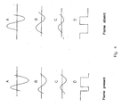
- Fig. 4 shows an example of the signal present as input/output at various points (in particular points A, B, C, D in the presence and absence of a flame) of the device 1.
- the embodiment illustrated shows a sinusoidal signal V1 with a duty cycle of 50%, it will be appreciated that the signal V1 may be any alternating signal having a predetermined set duty cycle.
- the signal V1 is sinusoidal with a duty cycle of 50%.
- the signal V1 is a triangular signal with a duty cycle of 50%.
- a triangular wave generator is in particular preferred in cases in which it is necessary to use an alternating current generator (for instance in cases in which connection to the electrical mains is impossible and it is therefore necessary to use, for instance, an appropriate battery).
- the potential difference between the base and emitter of the transmitter Q1 is such as to cut off the transistor Q1 for a time interval greater than the saturation interval as the signal supplying the base of the transistor is in negative voltage for a period longer than the period in which the base is supplied with positive voltage.
- the output signal V of the device 1 is therefore "high” for a longer period than when it is “low” with the result that its duty cycle increases (see the signals of Fig. 4 ). Consequently, the more the duty cycle of the input signal of the base of the transistor Q1 decreases, the more the duty cycle of the collector signal (i.e. the voltage V) increases.
- the second duty cycle of the collector voltage V is therefore proportional to the flame intensity detected, as shown in Fig. 2 : the abscissa shows the ionisation current (proportional to the flame intensity) and the ordinate shows the resulting duty cycle of the signal V.
- the various curves shown in Fig. 2 refer to a plurality of different devices 1, in particular including different sensors U1, in order to verify that their behaviour is analogous.
- the device 1 is appropriately dimensioned so that the saturation value is reached for the maximum flame levels generally encountered in the burners in which it is applied.
- Fig. 3 shows a graph similar to that of Fig. 2 obtained for three different operating temperatures of the device 1 equal to -20°C, 25°C and 70°C (in this case as well, simulations of different devices 1 including different sensors are given for each temperature).
- the collector voltage V is sampled at high frequency and the sample values are compared by the microprocessor with the predetermined levels of the control function.
- the invention thus achieves the proposed objects and provides the above-described advantages with respect to known solutions.
- the device for measuring flame intensity is invariable with respect to temperature variations, dispersions of the characteristics of components and variations of the supply voltage.
Landscapes
- Engineering & Computer Science (AREA)
- Chemical & Material Sciences (AREA)
- Combustion & Propulsion (AREA)
- Mechanical Engineering (AREA)
- General Engineering & Computer Science (AREA)
- Other Investigation Or Analysis Of Materials By Electrical Means (AREA)
- Photometry And Measurement Of Optical Pulse Characteristics (AREA)
Claims (16)
- Vorrichtung (1) zum Messen der Flammenintensität in einem Brenner, wobei an diese Vorrichtung (1) ein erstes Wechselspannungs-Signal (V1) mit einer ersten vorgegebenen Einschaltdauer angelegt wird, umfassend- einen Flammensensor (U1), der proportional zur Intensität der Flamme im Brenner einen Ionisationsstrom erzeugt,- Mittel (2) zum Variieren der ersten Einschaltdauer als Funktion des Ionisationsstroms, wobei an diese Variationsmittel (2) als Eingabe das erste Wechselspannungs-Signal (V1) und der Ionisationsstrom angelegt werden und sie als Ausgabe ein Wechselspannungs-Signal (V) mit einer zweiten Einschaltdauer erzeugen, die eine Funktion dieses Ionisationsstroms ist, wobei die Variationsmittel (2) mindestens ein Schaltelement (Q1) umfassen, dadurch gekennzeichnet, dass an das mindestens eine Schaltelement (Q1) als Eingabe ein zweites Wechselspannungs-Signal angelegt wird, das in Bezug auf das erste Wechselspannungs-Signal (V1) ein negatives Offset aufweist, wobei dieses Offset vom Wert des Ionisationsstroms zur Erde abhängig ist.
- Vorrichtung (1) zum Messen der Flammenintensität nach Anspruch 1, bei der die zweite Einschaltdauer zunimmt, wenn der Ionisationsstrom zunimmt.
- Vorrichtung (1) zum Messen der Flammenintensität nach Anspruch 2, bei der die zweite Einschaltdauer im Wesentlichen linear mindestens in einem Abschnitt zunimmt, wenn der Ionisationsstrom zunimmt.
- Vorrichtung (1) zum Messen der Flammenintensität nach einem der vorhergehenden Ansprüche, bei der das Schaltelement (Q1) einen Transistor umfasst und das zweite Wechselspannungs-Eingabesignal an der Basis dieses Transistors (Q1) angelegt wird.
- Vorrichtung (1) zum Messen der Flammenintensität nach Anspruch 4, bei der das zweite Wechselspannungs-Eingabesignal an der Basis des Transistors (Q1) derart ist, dass die Potentialdifferenz zwischen der Basis und dem Emitter des Transistors (Q1) zwischen Sättigungs- und Sperrwerten wechselt.
- Vorrichtung (1) zum Messen der Flammenintensität nach Anspruch 4 oder 5, bei der das Ausgabesignal (V) vom Variationsmittel (2), in Abhängigkeit vom Wechsel von Sättigung und Sperren des Transistors (Q1) unter dem Einfluss dieses negativen Offsets, zur Kollektorspannung des Transistors (Q1) mit der zweiten Einschaltdauer korrespondiert.
- Vorrichtung (1) zum Messen der Flammenintensität nach einem der vorhergehenden Ansprüche, bei der die Variationsmittel (2) Filtermittel (3) umfassen, an die als Eingabe das zweite Wechselspannungs-Signal angelegt wird und die als Ausgabe mit der Basis des Schaltelements (Q1) verbunden sind.
- Vorrichtung (1) zum Messen der Flammenintensität nach Anspruch 7, bei der die Filtermittel (3) mindestens einen Tiefpassfilter (4; 5) umfassen.
- Vorrichtung (1) zum Messen der Flammenintensität nach Anspruch 8, bei der der Tiefpassfilter (3) zwei parallele Tiefpassfilter (4; 5) umfasst.
- Vorrichtung (1) zum Messen der Flammenintensität nach einem oder mehreren der Ansprüche 7 bis 9, bei der der Ausgang der Filtermittel (3) als Ausgang zum Transistor (Q1) mittels Regulationsmitteln für die Basisspannung des Transistors (Q1) elektrisch verbunden ist, die die Basisspannung unter einen Maximalgrenzwert begrenzen, der für den Transistor (Q1) zulässig ist.
- Vorrichtung (1) zum Messen der Flammenintensität nach Anspruch 10, bei der die Regulationsmittel für die Basisspannung (6) eine Diode (D6) umfassen, die zwischen die Basis und den Emitter des Transistors (Q1) eingeschleift ist.
- Vorrichtung (1) zum Messen der Flammenintensität nach einem oder mehreren der Ansprüche 4 bis 11, bei der an die Variationsmittel (2) durch einen Generator Gleichspannung (Vcc) angelegt wird, die an den Kollektor des Transistors (Q1) angelegt wird, und die einen Widerstand (R5) am Kollektor des Transistors (Q1) umfassen.
- Vorrichtung (1) zum Messen der Flammenintensität nach einem oder mehreren der vorhergehenden Ansprüche, bei der die Variationsmittel (2) Widerstände eines Typs umfassen, der sich bei Temperaturveränderungen nicht verändert.
- Flammenintensität-Steuerungssystem (7), umfassend:- eine Vorrichtung (1) zum Messen der Flammenintensität nach einem oder mehreren der Ansprüche 1 bis 13, die als Ausgabe ein Wechselspannungs-Signal (V) mit einer zweiten Einschaltdauer erzeugt,- Mittel (8) zum Vergleichen der zweiten Einschaltdauer des von der Messvorrichtung (1) ausgegebenen Signals (V) mit einer Mehrzahl von Pegeln, die durch eine Steuerungsfunktion vorgegeben sind.
- Flammenintensität-Steuerungssystem (7) nach Anspruch 14, umfassend einen Isoliertransformator (9) für die Netzversorgung.
- Flammenintensität-Steuerungssystem (7) nach Anspruch 14 oder 15, bei dem die Vergleichsmittel (8) einen Mikroprozessor (µP) mit der Kollektorspannung (V) als Eingabe umfassen.
Applications Claiming Priority (1)
| Application Number | Priority Date | Filing Date | Title |
|---|---|---|---|
| PCT/IT2006/000352 WO2007132484A1 (en) | 2006-05-11 | 2006-05-11 | A device for measuring flame intensity |
Publications (2)
| Publication Number | Publication Date |
|---|---|
| EP2016336A1 EP2016336A1 (de) | 2009-01-21 |
| EP2016336B1 true EP2016336B1 (de) | 2014-07-09 |
Family
ID=37499503
Family Applications (1)
| Application Number | Title | Priority Date | Filing Date |
|---|---|---|---|
| EP06756288.4A Expired - Lifetime EP2016336B1 (de) | 2006-05-11 | 2006-05-11 | Vorrichtung zur messung der flammenintensität |
Country Status (2)
| Country | Link |
|---|---|
| EP (1) | EP2016336B1 (de) |
| WO (1) | WO2007132484A1 (de) |
Families Citing this family (2)
| Publication number | Priority date | Publication date | Assignee | Title |
|---|---|---|---|---|
| WO2009110015A1 (en) * | 2008-03-07 | 2009-09-11 | Bertelli & Partners S.R.L. | Improved method and device to detect the flame in a burner operating on a solid, liquid or gaseous combustible |
| WO2019122976A1 (en) * | 2017-12-21 | 2019-06-27 | Idea S.P.A. | Device and method for the control and detection of the flame of a gas burner |
Family Cites Families (3)
| Publication number | Priority date | Publication date | Assignee | Title |
|---|---|---|---|---|
| GB1277402A (en) * | 1968-08-27 | 1972-06-14 | United Gas Industries Ltd | Flame detection system |
| GB2367172B (en) * | 2000-04-26 | 2004-02-18 | Pektron Group Ltd | Detection apparatus and a method of detection |
| DE10023273A1 (de) * | 2000-05-12 | 2001-11-15 | Siemens Building Tech Ag | Messeinrichtung für eine Flamme |
-
2006
- 2006-05-11 WO PCT/IT2006/000352 patent/WO2007132484A1/en not_active Ceased
- 2006-05-11 EP EP06756288.4A patent/EP2016336B1/de not_active Expired - Lifetime
Also Published As
| Publication number | Publication date |
|---|---|
| EP2016336A1 (de) | 2009-01-21 |
| WO2007132484A1 (en) | 2007-11-22 |
Similar Documents
| Publication | Publication Date | Title |
|---|---|---|
| US6676404B2 (en) | Measuring device for a flame | |
| US6084518A (en) | Balanced charge flame characterization system and method | |
| US5472336A (en) | Flame rectification sensor employing pulsed excitation | |
| US8300381B2 (en) | Low cost high speed spark voltage and flame drive signal generator | |
| EP2265867B1 (de) | Verbesserte(s) verfahren und vorrichtung zur erfassung der flamme in einem mit einem festen, flüssigen oder gasförmigen brennstoff betriebenen brenner | |
| US6985080B2 (en) | Flame sense circuit and method with analog output | |
| KR102652853B1 (ko) | 고온표면 점화기에 대한 제어전략 | |
| US4461615A (en) | Combustion control device | |
| US6278260B1 (en) | Charging device which monitors charging by detecting a temperature of the battery and which includes compensation for increases or decreases in ambient temperature | |
| JP2001520361A (ja) | 火炎を監視する方法及び装置 | |
| CN112696717A (zh) | 一种炉灶的火焰检测方法 | |
| CN215808629U (zh) | 一种用于点火装置的离子探针式火焰检测系统 | |
| WO2007132484A1 (en) | A device for measuring flame intensity | |
| CA1094202A (en) | Digital logic for condition responsive sensor | |
| EP3728950B1 (de) | Vorrichtung und verfahren zur steuerung und detektion der flamme eines gasbrenners | |
| RU2440536C2 (ru) | Устройство для измерения интенсивности пламени | |
| CN112305055A (zh) | 一种燃气具的燃烧工况控制装置及控制方法 | |
| US8547104B2 (en) | Self power for ignition coil with integrated ion sense circuitry | |
| CN101246075A (zh) | 燃具电磁阀检测器 | |
| US20110248690A1 (en) | Power supply circuit for combustion appliance | |
| KR100789280B1 (ko) | 전류신호 분석에 의한 난방기의 가동시간 계측장치 | |
| CN113452328A (zh) | 一种信号放大模块及火焰检测电路 | |
| CN214750049U (zh) | 一种炉灶的火焰检测电路 | |
| US6890170B2 (en) | Heater with glow plug/flame monitor | |
| KR20010102745A (ko) | 비절연형 시스템의 출력측 누설 전류 검지 장치 |
Legal Events
| Date | Code | Title | Description |
|---|---|---|---|
| PUAI | Public reference made under article 153(3) epc to a published international application that has entered the european phase |
Free format text: ORIGINAL CODE: 0009012 |
|
| 17P | Request for examination filed |
Effective date: 20080926 |
|
| AK | Designated contracting states |
Kind code of ref document: A1 Designated state(s): AT BE BG CH CY CZ DE DK EE ES FI FR GB GR HU IE IS IT LI LT LU LV MC NL PL PT RO SE SI SK TR |
|
| AX | Request for extension of the european patent |
Extension state: AL BA HR MK YU |
|
| DAX | Request for extension of the european patent (deleted) | ||
| GRAP | Despatch of communication of intention to grant a patent |
Free format text: ORIGINAL CODE: EPIDOSNIGR1 |
|
| INTG | Intention to grant announced |
Effective date: 20140213 |
|
| GRAS | Grant fee paid |
Free format text: ORIGINAL CODE: EPIDOSNIGR3 |
|
| GRAA | (expected) grant |
Free format text: ORIGINAL CODE: 0009210 |
|
| AK | Designated contracting states |
Kind code of ref document: B1 Designated state(s): AT BE BG CH CY CZ DE DK EE ES FI FR GB GR HU IE IS IT LI LT LU LV MC NL PL PT RO SE SI SK TR |
|
| REG | Reference to a national code |
Ref country code: GB Ref legal event code: FG4D |
|
| REG | Reference to a national code |
Ref country code: AT Ref legal event code: REF Ref document number: 676714 Country of ref document: AT Kind code of ref document: T Effective date: 20140715 Ref country code: CH Ref legal event code: EP |
|
| REG | Reference to a national code |
Ref country code: IE Ref legal event code: FG4D |
|
| REG | Reference to a national code |
Ref country code: DE Ref legal event code: R096 Ref document number: 602006042212 Country of ref document: DE Effective date: 20140821 |
|
| REG | Reference to a national code |
Ref country code: NL Ref legal event code: T3 |
|
| REG | Reference to a national code |
Ref country code: AT Ref legal event code: MK05 Ref document number: 676714 Country of ref document: AT Kind code of ref document: T Effective date: 20140709 |
|
| REG | Reference to a national code |
Ref country code: LT Ref legal event code: MG4D |
|
| PG25 | Lapsed in a contracting state [announced via postgrant information from national office to epo] |
Ref country code: PT Free format text: LAPSE BECAUSE OF FAILURE TO SUBMIT A TRANSLATION OF THE DESCRIPTION OR TO PAY THE FEE WITHIN THE PRESCRIBED TIME-LIMIT Effective date: 20141110 Ref country code: SE Free format text: LAPSE BECAUSE OF FAILURE TO SUBMIT A TRANSLATION OF THE DESCRIPTION OR TO PAY THE FEE WITHIN THE PRESCRIBED TIME-LIMIT Effective date: 20140709 Ref country code: ES Free format text: LAPSE BECAUSE OF FAILURE TO SUBMIT A TRANSLATION OF THE DESCRIPTION OR TO PAY THE FEE WITHIN THE PRESCRIBED TIME-LIMIT Effective date: 20140709 Ref country code: LT Free format text: LAPSE BECAUSE OF FAILURE TO SUBMIT A TRANSLATION OF THE DESCRIPTION OR TO PAY THE FEE WITHIN THE PRESCRIBED TIME-LIMIT Effective date: 20140709 Ref country code: BG Free format text: LAPSE BECAUSE OF FAILURE TO SUBMIT A TRANSLATION OF THE DESCRIPTION OR TO PAY THE FEE WITHIN THE PRESCRIBED TIME-LIMIT Effective date: 20141009 Ref country code: GR Free format text: LAPSE BECAUSE OF FAILURE TO SUBMIT A TRANSLATION OF THE DESCRIPTION OR TO PAY THE FEE WITHIN THE PRESCRIBED TIME-LIMIT Effective date: 20141010 Ref country code: FI Free format text: LAPSE BECAUSE OF FAILURE TO SUBMIT A TRANSLATION OF THE DESCRIPTION OR TO PAY THE FEE WITHIN THE PRESCRIBED TIME-LIMIT Effective date: 20140709 |
|
| REG | Reference to a national code |
Ref country code: DE Ref legal event code: R082 Ref document number: 602006042212 Country of ref document: DE Representative=s name: DREISS PATENTANWAELTE PARTG MBB, DE |
|
| REG | Reference to a national code |
Ref country code: GB Ref legal event code: 732E Free format text: REGISTERED BETWEEN 20150122 AND 20150128 |
|
| PG25 | Lapsed in a contracting state [announced via postgrant information from national office to epo] |
Ref country code: LV Free format text: LAPSE BECAUSE OF FAILURE TO SUBMIT A TRANSLATION OF THE DESCRIPTION OR TO PAY THE FEE WITHIN THE PRESCRIBED TIME-LIMIT Effective date: 20140709 Ref country code: CY Free format text: LAPSE BECAUSE OF FAILURE TO SUBMIT A TRANSLATION OF THE DESCRIPTION OR TO PAY THE FEE WITHIN THE PRESCRIBED TIME-LIMIT Effective date: 20140709 Ref country code: PL Free format text: LAPSE BECAUSE OF FAILURE TO SUBMIT A TRANSLATION OF THE DESCRIPTION OR TO PAY THE FEE WITHIN THE PRESCRIBED TIME-LIMIT Effective date: 20140709 Ref country code: AT Free format text: LAPSE BECAUSE OF FAILURE TO SUBMIT A TRANSLATION OF THE DESCRIPTION OR TO PAY THE FEE WITHIN THE PRESCRIBED TIME-LIMIT Effective date: 20140709 Ref country code: IS Free format text: LAPSE BECAUSE OF FAILURE TO SUBMIT A TRANSLATION OF THE DESCRIPTION OR TO PAY THE FEE WITHIN THE PRESCRIBED TIME-LIMIT Effective date: 20141109 |
|
| REG | Reference to a national code |
Ref country code: DE Ref legal event code: R082 Ref document number: 602006042212 Country of ref document: DE Representative=s name: DREISS PATENTANWAELTE PARTG MBB, DE Effective date: 20150213 Ref country code: DE Ref legal event code: R081 Ref document number: 602006042212 Country of ref document: DE Owner name: SIT S.P.A., IT Free format text: FORMER OWNER: SIT LA PRECISA S.P.A., PADUA/PADOVA, IT Effective date: 20150213 |
|
| REG | Reference to a national code |
Ref country code: FR Ref legal event code: TP Owner name: SIT S.P.A., IT Effective date: 20150223 Ref country code: FR Ref legal event code: GC Effective date: 20150223 |
|
| REG | Reference to a national code |
Ref country code: DE Ref legal event code: R097 Ref document number: 602006042212 Country of ref document: DE |
|
| PG25 | Lapsed in a contracting state [announced via postgrant information from national office to epo] |
Ref country code: CZ Free format text: LAPSE BECAUSE OF FAILURE TO SUBMIT A TRANSLATION OF THE DESCRIPTION OR TO PAY THE FEE WITHIN THE PRESCRIBED TIME-LIMIT Effective date: 20140709 Ref country code: RO Free format text: LAPSE BECAUSE OF FAILURE TO SUBMIT A TRANSLATION OF THE DESCRIPTION OR TO PAY THE FEE WITHIN THE PRESCRIBED TIME-LIMIT Effective date: 20140709 Ref country code: DK Free format text: LAPSE BECAUSE OF FAILURE TO SUBMIT A TRANSLATION OF THE DESCRIPTION OR TO PAY THE FEE WITHIN THE PRESCRIBED TIME-LIMIT Effective date: 20140709 Ref country code: EE Free format text: LAPSE BECAUSE OF FAILURE TO SUBMIT A TRANSLATION OF THE DESCRIPTION OR TO PAY THE FEE WITHIN THE PRESCRIBED TIME-LIMIT Effective date: 20140709 Ref country code: SK Free format text: LAPSE BECAUSE OF FAILURE TO SUBMIT A TRANSLATION OF THE DESCRIPTION OR TO PAY THE FEE WITHIN THE PRESCRIBED TIME-LIMIT Effective date: 20140709 |
|
| PLBE | No opposition filed within time limit |
Free format text: ORIGINAL CODE: 0009261 |
|
| STAA | Information on the status of an ep patent application or granted ep patent |
Free format text: STATUS: NO OPPOSITION FILED WITHIN TIME LIMIT |
|
| REG | Reference to a national code |
Ref country code: NL Ref legal event code: SD Effective date: 20150602 |
|
| 26N | No opposition filed |
Effective date: 20150410 |
|
| PG25 | Lapsed in a contracting state [announced via postgrant information from national office to epo] |
Ref country code: SI Free format text: LAPSE BECAUSE OF FAILURE TO SUBMIT A TRANSLATION OF THE DESCRIPTION OR TO PAY THE FEE WITHIN THE PRESCRIBED TIME-LIMIT Effective date: 20140709 |
|
| REG | Reference to a national code |
Ref country code: CH Ref legal event code: PL |
|
| PG25 | Lapsed in a contracting state [announced via postgrant information from national office to epo] |
Ref country code: LI Free format text: LAPSE BECAUSE OF NON-PAYMENT OF DUE FEES Effective date: 20150531 Ref country code: LU Free format text: LAPSE BECAUSE OF FAILURE TO SUBMIT A TRANSLATION OF THE DESCRIPTION OR TO PAY THE FEE WITHIN THE PRESCRIBED TIME-LIMIT Effective date: 20150511 Ref country code: CH Free format text: LAPSE BECAUSE OF NON-PAYMENT OF DUE FEES Effective date: 20150531 Ref country code: MC Free format text: LAPSE BECAUSE OF FAILURE TO SUBMIT A TRANSLATION OF THE DESCRIPTION OR TO PAY THE FEE WITHIN THE PRESCRIBED TIME-LIMIT Effective date: 20140709 |
|
| REG | Reference to a national code |
Ref country code: IE Ref legal event code: MM4A |
|
| PG25 | Lapsed in a contracting state [announced via postgrant information from national office to epo] |
Ref country code: IE Free format text: LAPSE BECAUSE OF NON-PAYMENT OF DUE FEES Effective date: 20150511 |
|
| REG | Reference to a national code |
Ref country code: FR Ref legal event code: PLFP Year of fee payment: 11 |
|
| PG25 | Lapsed in a contracting state [announced via postgrant information from national office to epo] |
Ref country code: BE Free format text: LAPSE BECAUSE OF FAILURE TO SUBMIT A TRANSLATION OF THE DESCRIPTION OR TO PAY THE FEE WITHIN THE PRESCRIBED TIME-LIMIT Effective date: 20140709 |
|
| REG | Reference to a national code |
Ref country code: FR Ref legal event code: PLFP Year of fee payment: 12 |
|
| PG25 | Lapsed in a contracting state [announced via postgrant information from national office to epo] |
Ref country code: HU Free format text: LAPSE BECAUSE OF FAILURE TO SUBMIT A TRANSLATION OF THE DESCRIPTION OR TO PAY THE FEE WITHIN THE PRESCRIBED TIME-LIMIT; INVALID AB INITIO Effective date: 20060511 |
|
| REG | Reference to a national code |
Ref country code: NL Ref legal event code: RF Free format text: RIGHT OF PLEDGE, REMOVED Effective date: 20171121 |
|
| REG | Reference to a national code |
Ref country code: FR Ref legal event code: RG Effective date: 20180202 |
|
| REG | Reference to a national code |
Ref country code: FR Ref legal event code: PLFP Year of fee payment: 13 |
|
| PGFP | Annual fee paid to national office [announced via postgrant information from national office to epo] |
Ref country code: TR Payment date: 20200511 Year of fee payment: 15 Ref country code: NL Payment date: 20200527 Year of fee payment: 15 Ref country code: FR Payment date: 20200522 Year of fee payment: 15 |
|
| PGFP | Annual fee paid to national office [announced via postgrant information from national office to epo] |
Ref country code: GB Payment date: 20200527 Year of fee payment: 15 |
|
| PGFP | Annual fee paid to national office [announced via postgrant information from national office to epo] |
Ref country code: IT Payment date: 20210419 Year of fee payment: 16 Ref country code: DE Payment date: 20210520 Year of fee payment: 16 |
|
| REG | Reference to a national code |
Ref country code: NL Ref legal event code: MM Effective date: 20210601 |
|
| GBPC | Gb: european patent ceased through non-payment of renewal fee |
Effective date: 20210511 |
|
| PG25 | Lapsed in a contracting state [announced via postgrant information from national office to epo] |
Ref country code: GB Free format text: LAPSE BECAUSE OF NON-PAYMENT OF DUE FEES Effective date: 20210511 |
|
| PG25 | Lapsed in a contracting state [announced via postgrant information from national office to epo] |
Ref country code: NL Free format text: LAPSE BECAUSE OF NON-PAYMENT OF DUE FEES Effective date: 20210601 Ref country code: FR Free format text: LAPSE BECAUSE OF NON-PAYMENT OF DUE FEES Effective date: 20210531 |
|
| REG | Reference to a national code |
Ref country code: DE Ref legal event code: R119 Ref document number: 602006042212 Country of ref document: DE |
|
| PG25 | Lapsed in a contracting state [announced via postgrant information from national office to epo] |
Ref country code: DE Free format text: LAPSE BECAUSE OF NON-PAYMENT OF DUE FEES Effective date: 20221201 |
|
| PG25 | Lapsed in a contracting state [announced via postgrant information from national office to epo] |
Ref country code: IT Free format text: LAPSE BECAUSE OF NON-PAYMENT OF DUE FEES Effective date: 20220511 |
|
| PG25 | Lapsed in a contracting state [announced via postgrant information from national office to epo] |
Ref country code: TR Free format text: LAPSE BECAUSE OF NON-PAYMENT OF DUE FEES Effective date: 20210511 |