EP2016246B1 - Furniture hinge with damping device - Google Patents
Furniture hinge with damping device Download PDFInfo
- Publication number
- EP2016246B1 EP2016246B1 EP07728972A EP07728972A EP2016246B1 EP 2016246 B1 EP2016246 B1 EP 2016246B1 EP 07728972 A EP07728972 A EP 07728972A EP 07728972 A EP07728972 A EP 07728972A EP 2016246 B1 EP2016246 B1 EP 2016246B1
- Authority
- EP
- European Patent Office
- Prior art keywords
- box
- slider
- hinge according
- hinge
- cover
- Prior art date
- Legal status (The legal status is an assumption and is not a legal conclusion. Google has not performed a legal analysis and makes no representation as to the accuracy of the status listed.)
- Active
Links
Images


Classifications
-
- E—FIXED CONSTRUCTIONS
- E05—LOCKS; KEYS; WINDOW OR DOOR FITTINGS; SAFES
- E05F—DEVICES FOR MOVING WINGS INTO OPEN OR CLOSED POSITION; CHECKS FOR WINGS; WING FITTINGS NOT OTHERWISE PROVIDED FOR, CONCERNED WITH THE FUNCTIONING OF THE WING
- E05F5/00—Braking devices, e.g. checks; Stops; Buffers
- E05F5/006—Braking devices, e.g. checks; Stops; Buffers for hinges having a cup-shaped fixing part, e.g. for attachment to cabinets or furniture
-
- E—FIXED CONSTRUCTIONS
- E05—LOCKS; KEYS; WINDOW OR DOOR FITTINGS; SAFES
- E05D—HINGES OR SUSPENSION DEVICES FOR DOORS, WINDOWS OR WINGS
- E05D11/00—Additional features or accessories of hinges
- E05D11/10—Devices for preventing movement between relatively-movable hinge parts
-
- E—FIXED CONSTRUCTIONS
- E05—LOCKS; KEYS; WINDOW OR DOOR FITTINGS; SAFES
- E05D—HINGES OR SUSPENSION DEVICES FOR DOORS, WINDOWS OR WINGS
- E05D11/00—Additional features or accessories of hinges
- E05D11/10—Devices for preventing movement between relatively-movable hinge parts
- E05D11/1014—Devices for preventing movement between relatively-movable hinge parts for maintaining the hinge in only one position, e.g. closed
- E05D11/1021—Devices for preventing movement between relatively-movable hinge parts for maintaining the hinge in only one position, e.g. closed the hinge having two or more pins and being specially adapted for cabinets or furniture
-
- E—FIXED CONSTRUCTIONS
- E05—LOCKS; KEYS; WINDOW OR DOOR FITTINGS; SAFES
- E05D—HINGES OR SUSPENSION DEVICES FOR DOORS, WINDOWS OR WINGS
- E05D3/00—Hinges with pins
-
- E—FIXED CONSTRUCTIONS
- E05—LOCKS; KEYS; WINDOW OR DOOR FITTINGS; SAFES
- E05D—HINGES OR SUSPENSION DEVICES FOR DOORS, WINDOWS OR WINGS
- E05D7/00—Hinges or pivots of special construction
-
- E—FIXED CONSTRUCTIONS
- E05—LOCKS; KEYS; WINDOW OR DOOR FITTINGS; SAFES
- E05F—DEVICES FOR MOVING WINGS INTO OPEN OR CLOSED POSITION; CHECKS FOR WINGS; WING FITTINGS NOT OTHERWISE PROVIDED FOR, CONCERNED WITH THE FUNCTIONING OF THE WING
- E05F3/00—Closers or openers with braking devices, e.g. checks; Construction of pneumatic or liquid braking devices
-
- E—FIXED CONSTRUCTIONS
- E05—LOCKS; KEYS; WINDOW OR DOOR FITTINGS; SAFES
- E05F—DEVICES FOR MOVING WINGS INTO OPEN OR CLOSED POSITION; CHECKS FOR WINGS; WING FITTINGS NOT OTHERWISE PROVIDED FOR, CONCERNED WITH THE FUNCTIONING OF THE WING
- E05F5/00—Braking devices, e.g. checks; Stops; Buffers
- E05F5/02—Braking devices, e.g. checks; Stops; Buffers specially for preventing the slamming of swinging wings during final closing movement, e.g. jamb stops
-
- E—FIXED CONSTRUCTIONS
- E05—LOCKS; KEYS; WINDOW OR DOOR FITTINGS; SAFES
- E05Y—INDEXING SCHEME ASSOCIATED WITH SUBCLASSES E05D AND E05F, RELATING TO CONSTRUCTION ELEMENTS, ELECTRIC CONTROL, POWER SUPPLY, POWER SIGNAL OR TRANSMISSION, USER INTERFACES, MOUNTING OR COUPLING, DETAILS, ACCESSORIES, AUXILIARY OPERATIONS NOT OTHERWISE PROVIDED FOR, APPLICATION THEREOF
- E05Y2201/00—Constructional elements; Accessories therefor
- E05Y2201/20—Brakes; Disengaging means; Holders; Stops; Valves; Accessories therefor
- E05Y2201/21—Brakes
-
- E—FIXED CONSTRUCTIONS
- E05—LOCKS; KEYS; WINDOW OR DOOR FITTINGS; SAFES
- E05Y—INDEXING SCHEME ASSOCIATED WITH SUBCLASSES E05D AND E05F, RELATING TO CONSTRUCTION ELEMENTS, ELECTRIC CONTROL, POWER SUPPLY, POWER SIGNAL OR TRANSMISSION, USER INTERFACES, MOUNTING OR COUPLING, DETAILS, ACCESSORIES, AUXILIARY OPERATIONS NOT OTHERWISE PROVIDED FOR, APPLICATION THEREOF
- E05Y2201/00—Constructional elements; Accessories therefor
- E05Y2201/20—Brakes; Disengaging means; Holders; Stops; Valves; Accessories therefor
- E05Y2201/252—Type of friction
- E05Y2201/254—Fluid or viscous friction
-
- E—FIXED CONSTRUCTIONS
- E05—LOCKS; KEYS; WINDOW OR DOOR FITTINGS; SAFES
- E05Y—INDEXING SCHEME ASSOCIATED WITH SUBCLASSES E05D AND E05F, RELATING TO CONSTRUCTION ELEMENTS, ELECTRIC CONTROL, POWER SUPPLY, POWER SIGNAL OR TRANSMISSION, USER INTERFACES, MOUNTING OR COUPLING, DETAILS, ACCESSORIES, AUXILIARY OPERATIONS NOT OTHERWISE PROVIDED FOR, APPLICATION THEREOF
- E05Y2201/00—Constructional elements; Accessories therefor
- E05Y2201/20—Brakes; Disengaging means; Holders; Stops; Valves; Accessories therefor
- E05Y2201/262—Type of motion, e.g. braking
- E05Y2201/266—Type of motion, e.g. braking rotary
-
- E—FIXED CONSTRUCTIONS
- E05—LOCKS; KEYS; WINDOW OR DOOR FITTINGS; SAFES
- E05Y—INDEXING SCHEME ASSOCIATED WITH SUBCLASSES E05D AND E05F, RELATING TO CONSTRUCTION ELEMENTS, ELECTRIC CONTROL, POWER SUPPLY, POWER SIGNAL OR TRANSMISSION, USER INTERFACES, MOUNTING OR COUPLING, DETAILS, ACCESSORIES, AUXILIARY OPERATIONS NOT OTHERWISE PROVIDED FOR, APPLICATION THEREOF
- E05Y2201/00—Constructional elements; Accessories therefor
- E05Y2201/60—Suspension or transmission members; Accessories therefor
- E05Y2201/622—Suspension or transmission members elements
- E05Y2201/71—Toothed gearing
- E05Y2201/722—Racks
-
- E—FIXED CONSTRUCTIONS
- E05—LOCKS; KEYS; WINDOW OR DOOR FITTINGS; SAFES
- E05Y—INDEXING SCHEME ASSOCIATED WITH SUBCLASSES E05D AND E05F, RELATING TO CONSTRUCTION ELEMENTS, ELECTRIC CONTROL, POWER SUPPLY, POWER SIGNAL OR TRANSMISSION, USER INTERFACES, MOUNTING OR COUPLING, DETAILS, ACCESSORIES, AUXILIARY OPERATIONS NOT OTHERWISE PROVIDED FOR, APPLICATION THEREOF
- E05Y2600/00—Mounting or coupling arrangements for elements provided for in this subclass
- E05Y2600/40—Mounting location; Visibility of the elements
- E05Y2600/46—Mounting location; Visibility of the elements in or on the wing
-
- E—FIXED CONSTRUCTIONS
- E05—LOCKS; KEYS; WINDOW OR DOOR FITTINGS; SAFES
- E05Y—INDEXING SCHEME ASSOCIATED WITH SUBCLASSES E05D AND E05F, RELATING TO CONSTRUCTION ELEMENTS, ELECTRIC CONTROL, POWER SUPPLY, POWER SIGNAL OR TRANSMISSION, USER INTERFACES, MOUNTING OR COUPLING, DETAILS, ACCESSORIES, AUXILIARY OPERATIONS NOT OTHERWISE PROVIDED FOR, APPLICATION THEREOF
- E05Y2900/00—Application of doors, windows, wings or fittings thereof
- E05Y2900/20—Application of doors, windows, wings or fittings thereof for furniture, e.g. cabinets
Definitions
- the present invention relates to a furniture hinge, in particular a hinge with spring for doors, or in general for furniture parts suitable to be brought into motion, provided with a damping device which acts during opening and/or closing of the doors.
- Furniture provided with doors or wings to close compartments and which open by pivoting about a horizontal or vertical axis uses various types of hinge.
- a type which is very widely used today is one in which the hinges to support the doors in the closed position are not visible from the outside of the piece of furniture when the door is closed.
- Hinges of this type are today commonly used in the furniture industry as they have a series of advantages, which have determined their extensive use on the market. Some embodiments of known hinges are provided with springs of various types to produce a return force during closing or a pushing force during opening of the doors to which they are fitted. This allows very precise closing or opening of the doors.
- damping and/or braking devices of the door movement caused by the elastic reaction of the spring are desirable in these hinges.
- the object of these devices is above all to prevent noise caused during closing operations by doors banging shut against the body of the piece of furniture.
- Some hinges of the type known in the prior art are provided with a damping device wherein a rectangular slider, moved by the cam fitted to the rocker of the hinge, transmits the motion to a disc that is braked by the high viscosity grease.
- the known device is fitted from the outside beneath the box of the hinge and the cam of the rocker engages with the slider passing through an opening provided in the base of the same box.
- this arrangement makes the device subject to possible accidental or undesirable external actions, such as impact during production or during packaging of the hinges, or pressure due to the insertion of the hinge box into the milled holes of the doors when assembling the hinges on the furniture.
- the main object of the present invention is to produce a furniture hinge provided with a damping device that is insertable into the box of the hinge and fixable therein before the box is assembled with the other components of the hinge.
- the damping device is protected against external actions, such as impact or pressure that can damage or affect the functioning of the device, by the same box made of steel or of another rigid material.
- a further object is to produce a hinge having a configuration that allows a more practical use of the space inside said hinge, even making it possible to use decelerators based on systems known in the prior art, such as rotational decelerators or cylinder and piston decelerators.
- the present invention proposes to resolve the problems discussed above by producing a furniture hinge with damping device having the characteristics of the claim 1.
- the damping device of the hinge according to the invention can provide the hinge box itself as a component element thereof, or the damping device can consist entirely of elements that are separate from the box, which can be pre-mounted together and then inserted into the box properly provided with suitable means for fixing or blocking said elements.
- This modularity makes construction and final assembly much easier.
- the improved efficiency of the hinge is obtained by increasing the friction surfaces with the viscous medium present in suitable areas of the hinge and/or by allowing regulation of the trend of the angular velocity of at least one circular element, for example a disc, which acts as braking element in contact with the viscous medium.
- a further advantage is that the damping device, thanks to its compactness and being mounted inside the box element, is incorporated inside the thickness of the furniture door and is therefore invisible when the door is opened, also improving the aesthetic appearance.
- a hinge is represented, indicated as a whole with the reference 50, comprising a fixed element, or hinge arm 1, which is fixable on a base, or plate, in turn fixed integrally to a bearing wall of a side panel or any suitable element of a piece of furniture.
- the hinge is provided with two rockers 2 and 3, with a respective first end thereof pivoting about two respective pins 4, 5 housed in holes in the side walls of the arm 1.
- the arm 1 is connected to a box element 6, or simply box, fixed in a cavity produced in the inside wall of the door or wing of the piece of furniture, or of any other appropriate pivoting element of the piece of furniture.
- the two respective second ends of the rockers 2 and 3 are housed in rotation on two other respective pins 7, 8 with axes parallel to the first two pins 4, 5.
- the four pins 4, 5, 7, 8 form an articulated quadrilateral.
- an elastic element or spring 9 Around the articulation pin 5, connecting the rocker 3 to the arm 1, there is provided an elastic element or spring 9.
- One of the arms 10 of said elastic element is resting on the hinge arm 1, while the other arm 11 reacts on the rocker 2. Closing of the arms 10, 11 of the elastic element 9 is established so that this element 9 exerts a pushing force on the rocker 2 until the position shown in Figure 1 . Beyond this opening angle of the door, approximately from 15 to 20°, the elastic element 9 has a compression with a negligible application arm, so that the remaining part of the pivoting movement of the door takes place freely without being influenced by the presence of elastic forces.
- the elastic element 9 produces a return force in the closing direction which allows a precise and spontaneous closing of the door in the final angular space, with an amplitude of approximately 15 to 20°.
- a bushing 12 can be appropriately interposed between the elastic element 9 and the pin 5.
- the element 9 can be detached from the pin 5 and be anchored in a known way to the hinge arm 1.
- a damping and/or braking device 13 suitable to reduce jerky movements which take place during the opening and/or closing phases of the doors, reducing noise and allowing these phases to take place comfortably and smoothly.
- This device 13 comprises a housing formed of a casing or cover 14 and of part of the box element 6. Inside said housing there are advantageously inserted a slider 18 and at least one braking element immersed in a highly viscous medium, such as grease.
- the shape of the casing 14 is such as to allow it to be fixed to the box element 6 by means of the same pins 7, 8, about which the second ends of the rockers 2 and 3 respectively pivot. Said pins 7, 8 pass through the holes 70, 71 of the casing 14 and the corresponding holes 80, 81 on the box element 6.
- the inside of the casing 14 is provided with a hole or opening 15, which is substantially rectangular or square or of another shape, to allow a connection element, preferably a cam element 6 fixed to the lower end of the rocker 3, pivoting about the pin 8 for articulation with the box element, or integral therewith, to engage with the slider 18, thus controlling said slider in translation in a first or second direction in correspondence with the pivoting direction of the hinge.
- a connection element preferably a cam element 6 fixed to the lower end of the rocker 3, pivoting about the pin 8 for articulation with the box element, or integral therewith
- a first advantageous embodiment of the hinge according to the invention illustrated in Figures 1 to 6 , provides a box element or box 6, made of steel, of a standard size or drawn slightly deeper than the types of box known in the prior art but in such a way as not to make it difficult to insert said box in the milled holes on the doors of the furniture.
- Said box 6 is provided with at least one flange 90 for fixing to the inside wall of the door or wing of the element of piece of furniture.
- the box 6, as illustrated more clearly in Figure 6 is provided on its base with annular concentric grooves 40 and ribs 41 which can be coupled in a complementary way with similar grooves 40' and ribs 41' provided on the lower surface of a braking disc 23 and between which there is arranged the viscous grease.
- This advantageously makes the device undoubtedly silent and the braking force more effective thanks to the increased extension of the coupled and friction surfaces with the viscous medium.
- the braking disc 23 is provided on its upper surface with spiral grooves 30, in which a lower protuberance 29 of the slider 18 engages to convert the translation of the slider 18, transmitted to this by the cam element 16 of the rocker 3, into a rotation of the braking disc 23.
- the protuberance 29 engages with at least one of the spiral grooves 30 by means of a profile which is complementary to the profile with a saw-tooth cross-section of said grooves.
- the cam projection of the connection element 16 acts on corresponding projections of the slider 18 causing the translation thereof and, by means of the engagement of the protuberance 29 in the groove 30, the rotation of the braking disc 23 and thus the damping action.
- All the elements of the damping device are immersed in a viscous medium.
- the protuberance 29 is provided with a substantially pointed end 42, which allows a correct operation of the damping device of the hinge even in abnormal conditions, for example , when the door is not completely opened, but is immediately closed again after being moved only by a small angle from its rabbet position against the piece of furniture.
- the slider 18 can be in the position illustrated in Figure 1 , with the protuberance 29 resting on a crest formed by the spiral grooves 30, pushed by side projections of the cam element 16. If the door is closed again, the tip of the cam element 16 rests on the inclined surface of the pointed end 42 pushing it downwards so that it presses against the crests of the teeth formed by the grooves 30 generating a decelerated rotation of the braking disc 23 until reaching a new position of normal operation, obtaining the overall braking effect for the hinge.
- the inside of the casing 14 of the hinge according to the invention is substantially the same as the inside of a standard box of a known hinge, as illustrated more clearly in Figure 2 which shows a top view of the box 6 provided with the pre-mounted damping device.
- the outside surface of the casing 14 is substantially that of a cylinder, except in correspondence with the holes 70, 71 for housing the articulation pins 7, 8 of the rockers 2, 3 where there are provided flat surfaces parallel to one another and each oriented along a chord of the base circumference of said cylinder.
- the drawn part of the box 6 is also provided with a side wall that is substantially cylindrical, the shape of which corresponds to the outside shape of the casing 14 so that the respective holes 80, 81 for housing the pins 7, 8 of the rockers 2, 3 are, in the mounted position, aligned with the holes 70, 71 of the casing 14.
- the box 6 is provided with tabs 20 which are cut and project inwards. Said tabs 20 are suitable to push against corresponding stop planes 21 provided on the edge of the casing 14, so as to hold it in its pre-mounted position.
- Tabs 20 and stop planes 21 can, alternatively, be arranged respectively on a wall of the casing 14 and on an edge of the box 6. In this case the tabs project towards the outside.
- the slider 18 and the braking disc 23 are housed inside a lower cylindrical cavity 22, provided in the lower part of the casing 14, the edges of which act as a sealing element for the viscous grease.
- the base of the box 6 is completely smooth and the lower cylindrical cavity 22 of the casing, which houses the slider and the braking disc, is closed by a flat element 26, or closing plate of the damping device, provided with the concentric grooves 40 and ribs 41 which can be coupled with the respective ribs 41' and grooves 40' of the lower surface of the braking disc 23.
- This flat element 26 allows the damping device to be fastened shut by means of appropriate peripheral projections 24 suitable to engage in seats of a complementary shape provided on the lower edge of the casing 14, or said element 26 can be fixed to the casing 14, for example, by means of ultrasonic welding.
- the damping device thus assembled comprising casing 14, slider 18, braking disc 23 and flat element 26, can then be inserted and blocked in the box 6 by means of the aforesaid tabs 20 and stop planes 21 with a single, simple and quick operation.
- the box element therefore does not act as supporting element during mounting of the elements of the damping device.
- the box 6 with the pre-mounted damping device is ready to be assembled with the other components of the hinge in the usual way.
- the flat part of the crests of the ribs 41, 41' and the bottom of the grooves 40, 40' can, moreover, be produced with a rough finishing to promote adhesion of the viscous medium, for example high viscosity grease, in contact therewith.
- this embodiment makes it more difficult for the grease to move in a radial direction, so that the use of gaskets between the bottom of the box element 6 and the casing 14 or between said flat element 26 and the casing is unnecessary.
- the space comprised between the guiding side edges of the slider 18, parallel to the direction of translation of said slider, and the wall of the box 6 is used to house rotational decelerators of a known type, provided with toothed wheels 25 fitted to pins 17, perpendicular to the base of the box 6, and suitable to be made to rotate by a respective rack 45 provided along said side edges of the slider 18. Since the toothed wheels 25 are fitted to pins that are in turn provided with projecting parts (not illustrated in the figure) which rotate in an appropriate vessel and are immersed in a viscous fluid, a damping effect is generated during the rotation thereof in the door closing and/or opening phase.
- a fourth embodiment of the hinge schematically illustrated in Figure 10
- the space available between said guiding side edges of the slider 18 and the wall of the box 6 is used, instead, to obtain in both sides a cylindrical seat 46 wherein a piston 47 slides axially, possibly under the stress of a spring 48.
- the two pistons 47 have advantageously a common rod 49, bent in the shape of a C.
- Each cylindrical seat 46 is closed by a plug 60 with the relative gasket to contain a decelerating fluid, such as grease or oil.
- the slider 18 is suitably connected with the C-shaped rod 49 so as to transmit to said rod its translational motion generated by the pivoting of the rocker 3 of the hinge during the door closing phase.
- the spring 48 also known as a return spring, can be provided to ensure the return of the piston and, thus, of the slider instead of the specific return elements usually provided on the cam connection element 16.
- the hinge of the invention it is possible to choose to produce the damping and/or braking action in only one of the two opening and closing phases of the door or in both phases.
- connection element 16 can be produced by means of suitably shaped tabs provided in the same sheet metal of which the rocker 3 is made.
- the hinge of the invention in all the various embodiments, also allows efficient operation without variation to the overall dimensions of standard hinges, considering the great compactness of the damping device .
Landscapes
- Engineering & Computer Science (AREA)
- Mechanical Engineering (AREA)
- Hinges (AREA)
- Telephone Set Structure (AREA)
- Closing And Opening Devices For Wings, And Checks For Wings (AREA)
Abstract
Description
- The present invention relates to a furniture hinge, in particular a hinge with spring for doors, or in general for furniture parts suitable to be brought into motion, provided with a damping device which acts during opening and/or closing of the doors.
- Furniture provided with doors or wings to close compartments and which open by pivoting about a horizontal or vertical axis uses various types of hinge. A type which is very widely used today is one in which the hinges to support the doors in the closed position are not visible from the outside of the piece of furniture when the door is closed.
- Hinges of this type are today commonly used in the furniture industry as they have a series of advantages, which have determined their extensive use on the market. Some embodiments of known hinges are provided with springs of various types to produce a return force during closing or a pushing force during opening of the doors to which they are fitted. This allows very precise closing or opening of the doors.
- Nonetheless, damping and/or braking devices of the door movement caused by the elastic reaction of the spring are desirable in these hinges. The object of these devices is above all to prevent noise caused during closing operations by doors banging shut against the body of the piece of furniture.
- Some hinges of the type known in the prior art, such as in
DE 102 11 294 A1 , are provided with a damping device wherein a rectangular slider, moved by the cam fitted to the rocker of the hinge, transmits the motion to a disc that is braked by the high viscosity grease. The known device is fitted from the outside beneath the box of the hinge and the cam of the rocker engages with the slider passing through an opening provided in the base of the same box. - Disadvantageously this arrangement makes the device subject to possible accidental or undesirable external actions, such as impact during production or during packaging of the hinges, or pressure due to the insertion of the hinge box into the milled holes of the doors when assembling the hinges on the furniture.
- This impact or pressure can damage or in any case affect the functioning of the damping device or decelerator.
- Another drawback with this type of device can, moreover, be attributed to the presence of the base of the box between the cam of the rocker and the slider of the device, in that it limits the possibility of fully exploiting the small amount of space that is available to house the decelerator or the possibility of advantageously shaping the relative component elements thereof.
- Therefore, there is a need to produce a furniture hinge provided with damping device which is capable of overcoming the aforesaid drawbacks.
- The main object of the present invention is to produce a furniture hinge provided with a damping device that is insertable into the box of the hinge and fixable therein before the box is assembled with the other components of the hinge. In this way the damping device is protected against external actions, such as impact or pressure that can damage or affect the functioning of the device, by the same box made of steel or of another rigid material.
- A further object is to produce a hinge having a configuration that allows a more practical use of the space inside said hinge, even making it possible to use decelerators based on systems known in the prior art, such as rotational decelerators or cylinder and piston decelerators.
- Therefore, the present invention proposes to resolve the problems discussed above by producing a furniture hinge with damping device having the characteristics of the
claim 1. - Advantageously the damping device of the hinge according to the invention can provide the hinge box itself as a component element thereof, or the damping device can consist entirely of elements that are separate from the box, which can be pre-mounted together and then inserted into the box properly provided with suitable means for fixing or blocking said elements. This modularity makes construction and final assembly much easier.
- The improved efficiency of the hinge is obtained by increasing the friction surfaces with the viscous medium present in suitable areas of the hinge and/or by allowing regulation of the trend of the angular velocity of at least one circular element, for example a disc, which acts as braking element in contact with the viscous medium.
- Finally, a further advantage is that the damping device, thanks to its compactness and being mounted inside the box element, is incorporated inside the thickness of the furniture door and is therefore invisible when the door is opened, also improving the aesthetic appearance.
- The dependent claims describe preferred embodiments of the invention.
- Further characteristics and advantages of the invention will be more apparent in the light of the detailed description of preferred, although non-exclusive, embodiments of a furniture hinge with damping device illustrated, by way of a nonlimiting example, with the aid of the accompanying drawings wherein:
-
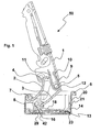
Figure 1 shows a sectional view of a first embodiment of the hinge of the invention in a half-open position; -
Figure 2 shows a top view of part of the hinge inFigure 1 ; -
Figure 3 shows a sectional view of a first component of the hinge inFigure 1 ; -
Figure 4 shows a side view of a second component of the hinge inFigure 1 ; -
Figures 5 and 6 show sectional views of further two components of the hinge inFigure 1 ; -
Figure 7 shows a sectional view of a second embodiment of the hinge of the invention in a half-open position; -
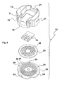
Figure 8 shows an exploded view of part of the hinge inFigure 7 ; -
Figure 9 shows a top view of part of a third embodiment of the hinge of the invention; -
Figure 10 shows a top view of part of a fourth embodiment of the hinge of the invention. - With reference to
Figure 1 , a hinge is represented, indicated as a whole with thereference 50, comprising a fixed element, orhinge arm 1, which is fixable on a base, or plate, in turn fixed integrally to a bearing wall of a side panel or any suitable element of a piece of furniture. - The hinge is provided with two
rockers arm 1. Thearm 1 is connected to abox element 6, or simply box, fixed in a cavity produced in the inside wall of the door or wing of the piece of furniture, or of any other appropriate pivoting element of the piece of furniture. The two respective second ends of therockers respective pins 7, 8 with axes parallel to the first two pins 4, 5. The fourpins 4, 5, 7, 8 form an articulated quadrilateral. - Around the articulation pin 5, connecting the
rocker 3 to thearm 1, there is provided an elastic element or spring 9. One of thearms 10 of said elastic element is resting on thehinge arm 1, while theother arm 11 reacts on therocker 2. Closing of thearms rocker 2 until the position shown inFigure 1 . Beyond this opening angle of the door, approximately from 15 to 20°, the elastic element 9 has a compression with a negligible application arm, so that the remaining part of the pivoting movement of the door takes place freely without being influenced by the presence of elastic forces. - On the other hand, in the closing phase of the door, the elastic element 9 produces a return force in the closing direction which allows a precise and spontaneous closing of the door in the final angular space, with an amplitude of approximately 15 to 20°.
- A
bushing 12 can be appropriately interposed between the elastic element 9 and the pin 5. Alternatively, the element 9 can be detached from the pin 5 and be anchored in a known way to thehinge arm 1. - Inside the
box element 6 there is mounted advantageously a damping and/orbraking device 13 suitable to reduce jerky movements which take place during the opening and/or closing phases of the doors, reducing noise and allowing these phases to take place comfortably and smoothly. - This
device 13 comprises a housing formed of a casing orcover 14 and of part of thebox element 6. Inside said housing there are advantageously inserted aslider 18 and at least one braking element immersed in a highly viscous medium, such as grease. - The shape of the
casing 14 is such as to allow it to be fixed to thebox element 6 by means of thesame pins 7, 8, about which the second ends of therockers pins 7, 8 pass through theholes casing 14 and thecorresponding holes box element 6. - The inside of the
casing 14 is provided with a hole or opening 15, which is substantially rectangular or square or of another shape, to allow a connection element, preferably acam element 6 fixed to the lower end of therocker 3, pivoting about the pin 8 for articulation with the box element, or integral therewith, to engage with theslider 18, thus controlling said slider in translation in a first or second direction in correspondence with the pivoting direction of the hinge. - A first advantageous embodiment of the hinge according to the invention, illustrated in
Figures 1 to 6 , provides a box element orbox 6, made of steel, of a standard size or drawn slightly deeper than the types of box known in the prior art but in such a way as not to make it difficult to insert said box in the milled holes on the doors of the furniture. - Said
box 6 is provided with at least oneflange 90 for fixing to the inside wall of the door or wing of the element of piece of furniture. - The
box 6, as illustrated more clearly inFigure 6 , is provided on its base with annularconcentric grooves 40 andribs 41 which can be coupled in a complementary way with similar grooves 40' and ribs 41' provided on the lower surface of abraking disc 23 and between which there is arranged the viscous grease. This advantageously makes the device undoubtedly silent and the braking force more effective thanks to the increased extension of the coupled and friction surfaces with the viscous medium. - The
braking disc 23 is provided on its upper surface withspiral grooves 30, in which alower protuberance 29 of theslider 18 engages to convert the translation of theslider 18, transmitted to this by thecam element 16 of therocker 3, into a rotation of thebraking disc 23. - In particular, the
protuberance 29 engages with at least one of thespiral grooves 30 by means of a profile which is complementary to the profile with a saw-tooth cross-section of said grooves. - In the door opening phase, as illustrated in
Figure 1 , translation of the slider takes place by a lifting of theprotuberance 29 which engages in a groove adjacent to the initial one, while thebraking disc 23 does not move. Theslider 18 is guided in translation by the edges of theopening 15 provided inside thecasing 14, which encloses theslider 18 and thebraking disc 23 between itself and thebox 6. - On the other hand, in the closing phase of the door, the cam projection of the
connection element 16 acts on corresponding projections of theslider 18 causing the translation thereof and, by means of the engagement of theprotuberance 29 in thegroove 30, the rotation of thebraking disc 23 and thus the damping action. All the elements of the damping device are immersed in a viscous medium. Advantageously theprotuberance 29 is provided with a substantiallypointed end 42, which allows a correct operation of the damping device of the hinge even in abnormal conditions, for example , when the door is not completely opened, but is immediately closed again after being moved only by a small angle from its rabbet position against the piece of furniture. In this situation theslider 18 can be in the position illustrated inFigure 1 , with theprotuberance 29 resting on a crest formed by thespiral grooves 30, pushed by side projections of thecam element 16. If the door is closed again, the tip of thecam element 16 rests on the inclined surface of thepointed end 42 pushing it downwards so that it presses against the crests of the teeth formed by thegrooves 30 generating a decelerated rotation of thebraking disc 23 until reaching a new position of normal operation, obtaining the overall braking effect for the hinge. - Without this
pointed end 42, if the door were closed again from the position inFigure 1 , thecam element 16 connected to therocker 3, by passing from a counter-clockwise to a clockwise movement, would move theprotuberance 29 of theslider 18 towards left, without this protuberance engaging with the profiles with saw tooth sections formed by thegrooves 30, and therefore without obtaining the braking effect. This expedient can also be used in the second embodiment of the hinge described below. - The inside of the
casing 14 of the hinge according to the invention is substantially the same as the inside of a standard box of a known hinge, as illustrated more clearly inFigure 2 which shows a top view of thebox 6 provided with the pre-mounted damping device. The outside surface of thecasing 14 is substantially that of a cylinder, except in correspondence with theholes rockers - The drawn part of the
box 6 is also provided with a side wall that is substantially cylindrical, the shape of which corresponds to the outside shape of thecasing 14 so that therespective holes pins 7, 8 of therockers holes casing 14. - Advantageously, in three points of its wall the
box 6 is provided withtabs 20 which are cut and project inwards. Saidtabs 20 are suitable to push against corresponding stop planes 21 provided on the edge of thecasing 14, so as to hold it in its pre-mounted position. -
Tabs 20 and stopplanes 21 can, alternatively, be arranged respectively on a wall of thecasing 14 and on an edge of thebox 6. In this case the tabs project towards the outside. - The
slider 18 and thebraking disc 23 are housed inside a lowercylindrical cavity 22, provided in the lower part of thecasing 14, the edges of which act as a sealing element for the viscous grease. - According to a second advantageous embodiment of the hinge of the invention, illustrated in
Figures 7 and8 , unlike the first embodiment described above, the base of thebox 6 is completely smooth and the lowercylindrical cavity 22 of the casing, which houses the slider and the braking disc, is closed by aflat element 26, or closing plate of the damping device, provided with theconcentric grooves 40 andribs 41 which can be coupled with the respective ribs 41' and grooves 40' of the lower surface of thebraking disc 23. Thisflat element 26 allows the damping device to be fastened shut by means of appropriateperipheral projections 24 suitable to engage in seats of a complementary shape provided on the lower edge of thecasing 14, or saidelement 26 can be fixed to thecasing 14, for example, by means of ultrasonic welding. - The damping device thus assembled, comprising
casing 14,slider 18,braking disc 23 andflat element 26, can then be inserted and blocked in thebox 6 by means of theaforesaid tabs 20 and stopplanes 21 with a single, simple and quick operation. In this case the box element therefore does not act as supporting element during mounting of the elements of the damping device. Thebox 6 with the pre-mounted damping device is ready to be assembled with the other components of the hinge in the usual way. - In these first two embodiments the flat part of the crests of the
ribs 41, 41' and the bottom of thegrooves 40, 40' can, moreover, be produced with a rough finishing to promote adhesion of the viscous medium, for example high viscosity grease, in contact therewith. Advantageously, this embodiment makes it more difficult for the grease to move in a radial direction, so that the use of gaskets between the bottom of thebox element 6 and thecasing 14 or between saidflat element 26 and the casing is unnecessary. - According to a third embodiment of the hinge of the invention, schematically illustrated in
Figure 9 , inside thecasing 14, the space comprised between the guiding side edges of theslider 18, parallel to the direction of translation of said slider, and the wall of thebox 6 is used to house rotational decelerators of a known type, provided withtoothed wheels 25 fitted topins 17, perpendicular to the base of thebox 6, and suitable to be made to rotate by arespective rack 45 provided along said side edges of theslider 18. Since thetoothed wheels 25 are fitted to pins that are in turn provided with projecting parts (not illustrated in the figure) which rotate in an appropriate vessel and are immersed in a viscous fluid, a damping effect is generated during the rotation thereof in the door closing and/or opening phase. - In a fourth embodiment of the hinge, schematically illustrated in
Figure 10 , the space available between said guiding side edges of theslider 18 and the wall of thebox 6 is used, instead, to obtain in both sides acylindrical seat 46 wherein apiston 47 slides axially, possibly under the stress of aspring 48. The twopistons 47 have advantageously acommon rod 49, bent in the shape of a C. Eachcylindrical seat 46 is closed by aplug 60 with the relative gasket to contain a decelerating fluid, such as grease or oil. - The
slider 18 is suitably connected with the C-shapedrod 49 so as to transmit to said rod its translational motion generated by the pivoting of therocker 3 of the hinge during the door closing phase. In this case thespring 48, also known as a return spring, can be provided to ensure the return of the piston and, thus, of the slider instead of the specific return elements usually provided on thecam connection element 16. - Advantageously, using the hinge of the invention it is possible to choose to produce the damping and/or braking action in only one of the two opening and closing phases of the door or in both phases.
- Optionally, the functions of the
connection element 16 can be produced by means of suitably shaped tabs provided in the same sheet metal of which therocker 3 is made. - The hinge of the invention, in all the various embodiments, also allows efficient operation without variation to the overall dimensions of standard hinges, considering the great compactness of the damping device .
- The specific methods of production described herein do not limit the content of this application, which covers all the embodiments of the invention defined by the claims.
Claims (16)
- Furniture hinge comprising
a first member (1) for fixing to an element of a piece of furniture,
a second member for fixing to a door of said element of a piece of furniture, comprising a box (6), said first member (1) being suitable to move with a relative pivoting motion about at least a first articulation pin (8) with said box (6),
a connection element (16) for connecting said first member (1) to damping means (13) of the furniture hinge for damping said pivoting motion, said dumping means (13) comprising- a slider (18) operated in translation by said connection element (16),- at least one damping element immersed in a viscous medium set in motion by movement of said slider (18) so as to produce a damping force,characterized in that the slider (18) and said at least one damping element are housed between a base of the box (6) and a substantially cylindrical cover (14) of the damping element, said base of the box (6) being integral and closed and said cover (14) being fixed internally to the box/and provided internally with an opening (15) for the connection between the connection element (16) and the slider (18). - Hinge according to claim 1, wherein a plate (26) is arranged between the base of the box (6) and the substantially cylindrical cover (14) of the damping element, said plate (26) being fixed to the lower edge of the cover (14) so as to enclose the slider (18) and said at least one damping element inside a cavity (22) produced in the cover (14).
- Hinge according to claim 1 or 2, wherein elastic fitting-in means (20, 21) are provided for a pre-assembly of said cover (14) in said box (6).
- Hinge according to claim 3, wherein said elastic fitting-in means comprise tabs (20) suitable to push against corresponding stop planes (21), said tabs and said stop planes being respectively provided on walls of the box (6) and of the cover (14) or vice versa.
- Hinge according to claim 4, wherein the tabs (20) and the stop planes (21) are provided respectively in three corresponding points of the walls of the box and of the cover.
- Hinge according to any one of the previous claims, wherein the box (6) is provided with at least one fixing flange (90) for a fixing to the door of said element of piece of furniture.
- Hinge according to any one of the previous claims, wherein said connection element is a cam element (16).
- Hinge according to any one of the previous claims, wherein said at least one damping element is a disc (23) having a substantially flat shape suitable to pivot about an axis perpendicular to the direction of said translation in order to generate a braking force in correspondence with a movement of the hinge.
- Hinge according to claim 8, wherein there are provided kinematic means for converting motion suitable to convert the translation of the slider into a rotation of the disc (23) about the axis, said kinematic means comprising a series of grooves (30) on a first surface of the disc (23) and a protuberance (29) fixed to the slider (18), suitable to engage with at least one groove (30), having a shape so as to generate a rotation of the disc only in one direction of translation of the slider.
- Hinge according to claim 9, wherein the grooves (30) are spirally shaped and have profiles with saw-tooth cross-sections, and the protuberance (29) on the slider (18) has a profile with a cross-section having a shape that is complementary to the profiles of the grooves (30).
- Hinge according to claim 10, wherein the protuberance (29) on the slider (18) is provided with one substantially pointed end (42), suitable to press against the profiles with saw-tooth cross-sections of the spiral grooves (30) in the door closing phase starting from a partially open position of said door.
- Hinge according to one of the claims from 8 to 11, wherein suitable annular concentric grooves (40') and ribs (41') are provided on a second surface of the disc (23) engaged respectively in complementary ribs (41) and grooves (40) provided on the base of the box (6) or on the plate (26) arranged between said second surface and said base of the box.
- Hinge according to one of the claims from 1 to 7, wherein said at least one damping element comprises toothed wheels (25) arranged laterally in relation to the slider and engaged with respective racks (45) produced on side edges of said slider so as to generate a rotation of said toothed wheels about a respective axis in correspondence with a translation of the slider.
- Hinge according to one of the claims from 1 to 7, wherein said at least one damping element comprises pistons (47) axially sliding in cylindrical seats (46) containing a viscous medium and arranged laterally in relation to the slider, said pistons (47) sharing a rod (49) in common which is suitably connected to the slider (18) so that the latter can transmit its translational motion to the pistons (47).
- Hinge according to one of the previous claims, wherein said first member comprises two elements, the first of said elements being a fixing arm (1) for a fixing to said element of piece of furniture and the second of said elements being a first rocker (3) suitable to pivot about the first articulation pin (8) with said box (6) and about a second articulation pin (5) with said fixing arm (1), and there is provided a second rocker (2) suitable to pivot about a respective first articulation pin (7) with said box (6) and about a respective second articulation pin (4) with said fixing arm (1).
- Hinge according to claim 15, wherein there are provided fixing means for fixing box (6) and cover (14) comprising the articulation pins (7, 8), suitable to engage first holes (70, 71) of the cover (14) and corresponding second holes (80, 81) of the box (6).
Priority Applications (2)
| Application Number | Priority Date | Filing Date | Title |
|---|---|---|---|
| SI200730949T SI2016246T1 (en) | 2006-05-11 | 2007-05-10 | Furniture hinge with damping device |
| PL07728972T PL2016246T3 (en) | 2006-05-11 | 2007-05-10 | Furniture hinge with damping device |
Applications Claiming Priority (2)
| Application Number | Priority Date | Filing Date | Title |
|---|---|---|---|
| IT000081U ITRM20060081U1 (en) | 2006-05-11 | 2006-05-11 | HINGE FOR MOBILE WITH DAMPING DEVICE |
| PCT/EP2007/054520 WO2007131933A1 (en) | 2006-05-11 | 2007-05-10 | Furniture hinge with damping device |
Publications (2)
| Publication Number | Publication Date |
|---|---|
| EP2016246A1 EP2016246A1 (en) | 2009-01-21 |
| EP2016246B1 true EP2016246B1 (en) | 2012-03-28 |
Family
ID=37081266
Family Applications (1)
| Application Number | Title | Priority Date | Filing Date |
|---|---|---|---|
| EP07728972A Active EP2016246B1 (en) | 2006-05-11 | 2007-05-10 | Furniture hinge with damping device |
Country Status (13)
| Country | Link |
|---|---|
| US (1) | US7810212B2 (en) |
| EP (1) | EP2016246B1 (en) |
| JP (1) | JP5167247B2 (en) |
| KR (1) | KR101361926B1 (en) |
| CN (1) | CN101356335B (en) |
| AT (1) | ATE551485T1 (en) |
| BR (1) | BRPI0706052B1 (en) |
| ES (1) | ES2384530T3 (en) |
| IT (1) | ITRM20060081U1 (en) |
| PL (1) | PL2016246T3 (en) |
| SI (1) | SI2016246T1 (en) |
| TW (1) | TWI399477B (en) |
| WO (1) | WO2007131933A1 (en) |
Cited By (1)
| Publication number | Priority date | Publication date | Assignee | Title |
|---|---|---|---|---|
| US10240379B2 (en) | 2014-12-23 | 2019-03-26 | Arturo Salice S.P.A. | Hinge for pieces of furniture with deactivatable deceleration device |
Families Citing this family (23)
| Publication number | Priority date | Publication date | Assignee | Title |
|---|---|---|---|---|
| ITMI20072146A1 (en) * | 2007-11-09 | 2009-05-10 | Salice Arturo Spa | DECELERATION DEVICE FOR MOBILE HINGE AND MOBILE HINGE THAT PRESENTS THAT DECELERATION DEVICE |
| CN101932786B (en) * | 2008-01-22 | 2014-09-17 | 格拉斯美国公司 | Damping mechanism for cabinet hinge assembly |
| ITMI20080465A1 (en) * | 2008-03-19 | 2009-09-20 | Salice Arturo Spa | DEVICE DOES DECELERATION OF THE ROTATION OF A HINGE PARTICULARLY FOR FURNITURE AND HINGE PARTICULARLY FOR FURNITURE WHICH PRESENTS THIS DECELERATION DEVICE |
| AT508069B1 (en) * | 2009-03-25 | 2015-03-15 | Blum Gmbh Julius | FURNITURE HINGE |
| AT15239U1 (en) * | 2009-03-25 | 2017-04-15 | Blum Gmbh Julius | hinge |
| AT508068B1 (en) * | 2009-03-25 | 2016-11-15 | Blum Gmbh Julius | FURNITURE HINGE |
| JP6174504B2 (en) * | 2014-03-05 | 2017-08-02 | 日東工器株式会社 | Hidden door closer set between the front and rear of the hinged door |
| DE102014106911A1 (en) * | 2014-05-16 | 2015-11-19 | Hettich-Oni Gmbh & Co. Kg | Hinge for furniture or household appliances |
| WO2016102215A1 (en) | 2014-12-23 | 2016-06-30 | Arturo Salice S.P.A. | Decelerated hinge for pieces of furniture |
| PT3812545T (en) * | 2015-04-30 | 2023-04-03 | Salice Arturo Spa | Decelerated hinge for furniture |
| DE102015106919A1 (en) * | 2015-05-04 | 2016-11-10 | Samet Kalip Ve Maden Esya San. Ve Tic. A.S. | Furniture hinge with a damper |
| AT517377B1 (en) * | 2015-06-18 | 2017-09-15 | Blum Gmbh Julius | hinge |
| DE202015105233U1 (en) * | 2015-10-05 | 2017-01-09 | Grass Gmbh & Co. Kg | Hinge for a movable furniture part attached to a body of a piece of furniture |
| US10030427B2 (en) | 2016-06-23 | 2018-07-24 | Hardware Resources, Inc. | Compact hinge apparatus and method of use |
| US9874049B1 (en) | 2016-08-11 | 2018-01-23 | Hardware Resources, Inc. | Compact hinge apparatus and method of use |
| IT201700044196A1 (en) * | 2017-04-21 | 2018-10-21 | Effegi Brevetti Srl | MOVEMENT MECHANISM OF A FURNITURE DOOR |
| DE102018100672A1 (en) * | 2018-01-12 | 2019-07-18 | Hettich-Oni Gmbh & Co. Kg | Furniture hinge, furniture panel and furniture body |
| USD855438S1 (en) * | 2018-03-22 | 2019-08-06 | Clopay Building Products Company, Inc. | Garage door cam |
| IT201900010089A1 (en) * | 2019-06-26 | 2020-12-26 | Salice Arturo Spa | Furniture hinge. |
| IT201900014091A1 (en) * | 2019-08-06 | 2021-02-06 | Salice Arturo Spa | Hinge for furniture doors or similar and furniture provided with the hinge itself. |
| CN114341454B (en) * | 2019-09-05 | 2023-11-03 | 沙美卡尺和矿业灯具有限公司 | Furniture hinge with damping mechanism |
| USD932279S1 (en) | 2020-01-17 | 2021-10-05 | Julius Blum Gmbh | Furniture hinge |
| CN113802943B (en) * | 2021-08-23 | 2024-10-01 | 陈思佳 | Buffer hinge |
Family Cites Families (16)
| Publication number | Priority date | Publication date | Assignee | Title |
|---|---|---|---|---|
| GB1129817A (en) * | 1964-12-10 | 1968-10-09 | Nash Alan R B | Improvements in or relating to rotary dampers |
| DE2143672A1 (en) * | 1971-09-01 | 1973-03-15 | Heinze Fa R | HINGE HOUSING WITH BEARING FASTENING IN A MATCHED RECESS OF A FURNITURE DOOR OR WALL |
| JPS58782Y2 (en) * | 1980-10-31 | 1983-01-07 | リョービ株式会社 | Overhead door closer |
| DE3120201A1 (en) * | 1981-05-21 | 1982-12-23 | Paul Hettich & Co, 4983 Kirchlengern | "FURNITURE HINGE WITH LOCKING DEVICE" |
| JPS59222631A (en) * | 1983-06-01 | 1984-12-14 | Nifco Inc | Rotary damper device |
| JP2885521B2 (en) * | 1991-01-25 | 1999-04-26 | 桂川電機株式会社 | Color electrophotographic equipment |
| JP2568556Y2 (en) * | 1991-07-05 | 1998-04-15 | オイレス工業株式会社 | Rotating window brake |
| US6298960B1 (en) * | 2000-05-30 | 2001-10-09 | Illinois Tool Works Inc. | Small viscous precision damper |
| IT249824Y1 (en) * | 2000-10-10 | 2003-06-05 | Salice Arturo Spa | HINGE FOR FURNITURE WITH DEVICE FOR SLOWED DOOR CLOSING |
| DE10211294B4 (en) * | 2002-03-14 | 2013-10-17 | Grass Gmbh | Furniture fitting with brake and damping device |
| DE20205905U1 (en) * | 2002-04-16 | 2002-07-11 | Julius Blum Ges.m.b.H., Höchst | fluid damper |
| DE20212022U1 (en) * | 2002-08-05 | 2002-09-26 | Arturo Salice S.P.A., Novedrate, Como | hinge |
| TW589434B (en) * | 2002-11-13 | 2004-06-01 | Salice Arturo Spa | Hinge |
| AT502613B1 (en) * | 2003-04-15 | 2007-08-15 | Blum Gmbh Julius | DAMPER WITH HOUSING |
| ITRM20030086U1 (en) * | 2003-05-14 | 2004-11-15 | Salice Arturo Spa | HINGE WITH SPRING FOR FURNITURE. |
| ITRM20040179U1 (en) | 2004-11-12 | 2005-02-12 | Salice Arturo Spa | HINGE FOR FURNITURE WITH DAMPING DEVICE. |
-
2006
- 2006-05-11 IT IT000081U patent/ITRM20060081U1/en unknown
-
2007
- 2007-03-28 TW TW096110672A patent/TWI399477B/en active
- 2007-05-10 SI SI200730949T patent/SI2016246T1/en unknown
- 2007-05-10 US US12/093,361 patent/US7810212B2/en not_active Expired - Fee Related
- 2007-05-10 KR KR1020087009787A patent/KR101361926B1/en not_active Expired - Fee Related
- 2007-05-10 PL PL07728972T patent/PL2016246T3/en unknown
- 2007-05-10 CN CN2007800013207A patent/CN101356335B/en active Active
- 2007-05-10 JP JP2009508388A patent/JP5167247B2/en not_active Expired - Fee Related
- 2007-05-10 BR BRPI0706052-1A patent/BRPI0706052B1/en not_active IP Right Cessation
- 2007-05-10 WO PCT/EP2007/054520 patent/WO2007131933A1/en not_active Ceased
- 2007-05-10 AT AT07728972T patent/ATE551485T1/en active
- 2007-05-10 ES ES07728972T patent/ES2384530T3/en active Active
- 2007-05-10 EP EP07728972A patent/EP2016246B1/en active Active
Cited By (1)
| Publication number | Priority date | Publication date | Assignee | Title |
|---|---|---|---|---|
| US10240379B2 (en) | 2014-12-23 | 2019-03-26 | Arturo Salice S.P.A. | Hinge for pieces of furniture with deactivatable deceleration device |
Also Published As
| Publication number | Publication date |
|---|---|
| KR20090006049A (en) | 2009-01-14 |
| ES2384530T3 (en) | 2012-07-06 |
| JP5167247B2 (en) | 2013-03-21 |
| JP2009536700A (en) | 2009-10-15 |
| TWI399477B (en) | 2013-06-21 |
| KR101361926B1 (en) | 2014-02-12 |
| EP2016246A1 (en) | 2009-01-21 |
| HK1127105A1 (en) | 2009-09-18 |
| US7810212B2 (en) | 2010-10-12 |
| ATE551485T1 (en) | 2012-04-15 |
| BRPI0706052A2 (en) | 2011-03-22 |
| CN101356335B (en) | 2012-07-04 |
| PL2016246T3 (en) | 2012-09-28 |
| WO2007131933A1 (en) | 2007-11-22 |
| CN101356335A (en) | 2009-01-28 |
| US20090049645A1 (en) | 2009-02-26 |
| TW200745433A (en) | 2007-12-16 |
| ITRM20060081U1 (en) | 2007-11-12 |
| SI2016246T1 (en) | 2012-08-31 |
| BRPI0706052B1 (en) | 2017-10-31 |
Similar Documents
| Publication | Publication Date | Title |
|---|---|---|
| EP2016246B1 (en) | Furniture hinge with damping device | |
| US7874043B2 (en) | Furniture hinge with damping device | |
| EP1994248B1 (en) | Furniture hinge with damping device | |
| EP1969200B1 (en) | Furniture hinge | |
| US20120210540A1 (en) | Door actuator | |
| EP1856357B1 (en) | Furniture hinge | |
| WO2010082028A1 (en) | Damped hinge assemblies | |
| JPWO2005095742A1 (en) | Hinge with damper | |
| EP1809843A1 (en) | Furniture hinge with damping device | |
| KR20080078532A (en) | Furniture hinge | |
| KR20210091881A (en) | Furniture hinge braking system for increased durability | |
| HK1127105B (en) | Furniture hinge with damping device | |
| KR200326948Y1 (en) | Door closer |
Legal Events
| Date | Code | Title | Description |
|---|---|---|---|
| PUAI | Public reference made under article 153(3) epc to a published international application that has entered the european phase |
Free format text: ORIGINAL CODE: 0009012 |
|
| 17P | Request for examination filed |
Effective date: 20080508 |
|
| AK | Designated contracting states |
Kind code of ref document: A1 Designated state(s): AT BE BG CH CY CZ DE DK EE ES FI FR GB GR HU IE IS IT LI LT LU LV MC MT NL PL PT RO SE SI SK TR |
|
| AX | Request for extension of the european patent |
Extension state: AL BA HR MK RS |
|
| GRAP | Despatch of communication of intention to grant a patent |
Free format text: ORIGINAL CODE: EPIDOSNIGR1 |
|
| DAX | Request for extension of the european patent (deleted) | ||
| GRAS | Grant fee paid |
Free format text: ORIGINAL CODE: EPIDOSNIGR3 |
|
| GRAA | (expected) grant |
Free format text: ORIGINAL CODE: 0009210 |
|
| AK | Designated contracting states |
Kind code of ref document: B1 Designated state(s): AT BE BG CH CY CZ DE DK EE ES FI FR GB GR HU IE IS IT LI LT LU LV MC MT NL PL PT RO SE SI SK TR |
|
| REG | Reference to a national code |
Ref country code: GB Ref legal event code: FG4D |
|
| REG | Reference to a national code |
Ref country code: CH Ref legal event code: EP |
|
| REG | Reference to a national code |
Ref country code: AT Ref legal event code: REF Ref document number: 551485 Country of ref document: AT Kind code of ref document: T Effective date: 20120415 |
|
| REG | Reference to a national code |
Ref country code: IE Ref legal event code: FG4D |
|
| REG | Reference to a national code |
Ref country code: DE Ref legal event code: R096 Ref document number: 602007021610 Country of ref document: DE Effective date: 20120524 |
|
| REG | Reference to a national code |
Ref country code: ES Ref legal event code: FG2A Ref document number: 2384530 Country of ref document: ES Kind code of ref document: T3 Effective date: 20120706 |
|
| REG | Reference to a national code |
Ref country code: NL Ref legal event code: VDEP Effective date: 20120328 |
|
| PG25 | Lapsed in a contracting state [announced via postgrant information from national office to epo] |
Ref country code: LT Free format text: LAPSE BECAUSE OF FAILURE TO SUBMIT A TRANSLATION OF THE DESCRIPTION OR TO PAY THE FEE WITHIN THE PRESCRIBED TIME-LIMIT Effective date: 20120328 |
|
| LTIE | Lt: invalidation of european patent or patent extension |
Effective date: 20120328 |
|
| PG25 | Lapsed in a contracting state [announced via postgrant information from national office to epo] |
Ref country code: GR Free format text: LAPSE BECAUSE OF FAILURE TO SUBMIT A TRANSLATION OF THE DESCRIPTION OR TO PAY THE FEE WITHIN THE PRESCRIBED TIME-LIMIT Effective date: 20120629 Ref country code: FI Free format text: LAPSE BECAUSE OF FAILURE TO SUBMIT A TRANSLATION OF THE DESCRIPTION OR TO PAY THE FEE WITHIN THE PRESCRIBED TIME-LIMIT Effective date: 20120328 Ref country code: LV Free format text: LAPSE BECAUSE OF FAILURE TO SUBMIT A TRANSLATION OF THE DESCRIPTION OR TO PAY THE FEE WITHIN THE PRESCRIBED TIME-LIMIT Effective date: 20120328 |
|
| PG25 | Lapsed in a contracting state [announced via postgrant information from national office to epo] |
Ref country code: CY Free format text: LAPSE BECAUSE OF FAILURE TO SUBMIT A TRANSLATION OF THE DESCRIPTION OR TO PAY THE FEE WITHIN THE PRESCRIBED TIME-LIMIT Effective date: 20120328 |
|
| REG | Reference to a national code |
Ref country code: PL Ref legal event code: T3 |
|
| PG25 | Lapsed in a contracting state [announced via postgrant information from national office to epo] |
Ref country code: IS Free format text: LAPSE BECAUSE OF FAILURE TO SUBMIT A TRANSLATION OF THE DESCRIPTION OR TO PAY THE FEE WITHIN THE PRESCRIBED TIME-LIMIT Effective date: 20120728 Ref country code: EE Free format text: LAPSE BECAUSE OF FAILURE TO SUBMIT A TRANSLATION OF THE DESCRIPTION OR TO PAY THE FEE WITHIN THE PRESCRIBED TIME-LIMIT Effective date: 20120328 Ref country code: RO Free format text: LAPSE BECAUSE OF FAILURE TO SUBMIT A TRANSLATION OF THE DESCRIPTION OR TO PAY THE FEE WITHIN THE PRESCRIBED TIME-LIMIT Effective date: 20120328 Ref country code: SE Free format text: LAPSE BECAUSE OF FAILURE TO SUBMIT A TRANSLATION OF THE DESCRIPTION OR TO PAY THE FEE WITHIN THE PRESCRIBED TIME-LIMIT Effective date: 20120328 Ref country code: BE Free format text: LAPSE BECAUSE OF FAILURE TO SUBMIT A TRANSLATION OF THE DESCRIPTION OR TO PAY THE FEE WITHIN THE PRESCRIBED TIME-LIMIT Effective date: 20120328 |
|
| REG | Reference to a national code |
Ref country code: HU Ref legal event code: AG4A Ref document number: E014176 Country of ref document: HU |
|
| PG25 | Lapsed in a contracting state [announced via postgrant information from national office to epo] |
Ref country code: PT Free format text: LAPSE BECAUSE OF FAILURE TO SUBMIT A TRANSLATION OF THE DESCRIPTION OR TO PAY THE FEE WITHIN THE PRESCRIBED TIME-LIMIT Effective date: 20120730 Ref country code: SK Free format text: LAPSE BECAUSE OF FAILURE TO SUBMIT A TRANSLATION OF THE DESCRIPTION OR TO PAY THE FEE WITHIN THE PRESCRIBED TIME-LIMIT Effective date: 20120328 |
|
| PG25 | Lapsed in a contracting state [announced via postgrant information from national office to epo] |
Ref country code: MC Free format text: LAPSE BECAUSE OF NON-PAYMENT OF DUE FEES Effective date: 20120531 |
|
| REG | Reference to a national code |
Ref country code: CH Ref legal event code: PL |
|
| PG25 | Lapsed in a contracting state [announced via postgrant information from national office to epo] |
Ref country code: CH Free format text: LAPSE BECAUSE OF NON-PAYMENT OF DUE FEES Effective date: 20120531 Ref country code: LI Free format text: LAPSE BECAUSE OF NON-PAYMENT OF DUE FEES Effective date: 20120531 Ref country code: DK Free format text: LAPSE BECAUSE OF FAILURE TO SUBMIT A TRANSLATION OF THE DESCRIPTION OR TO PAY THE FEE WITHIN THE PRESCRIBED TIME-LIMIT Effective date: 20120328 Ref country code: NL Free format text: LAPSE BECAUSE OF FAILURE TO SUBMIT A TRANSLATION OF THE DESCRIPTION OR TO PAY THE FEE WITHIN THE PRESCRIBED TIME-LIMIT Effective date: 20120328 |
|
| PLBE | No opposition filed within time limit |
Free format text: ORIGINAL CODE: 0009261 |
|
| STAA | Information on the status of an ep patent application or granted ep patent |
Free format text: STATUS: NO OPPOSITION FILED WITHIN TIME LIMIT |
|
| GBPC | Gb: european patent ceased through non-payment of renewal fee |
Effective date: 20120628 |
|
| REG | Reference to a national code |
Ref country code: IE Ref legal event code: MM4A |
|
| REG | Reference to a national code |
Ref country code: FR Ref legal event code: ST Effective date: 20130131 |
|
| 26N | No opposition filed |
Effective date: 20130103 |
|
| REG | Reference to a national code |
Ref country code: DE Ref legal event code: R097 Ref document number: 602007021610 Country of ref document: DE Effective date: 20130103 |
|
| PG25 | Lapsed in a contracting state [announced via postgrant information from national office to epo] |
Ref country code: GB Free format text: LAPSE BECAUSE OF NON-PAYMENT OF DUE FEES Effective date: 20120628 Ref country code: FR Free format text: LAPSE BECAUSE OF NON-PAYMENT OF DUE FEES Effective date: 20120531 Ref country code: IE Free format text: LAPSE BECAUSE OF NON-PAYMENT OF DUE FEES Effective date: 20120510 |
|
| PG25 | Lapsed in a contracting state [announced via postgrant information from national office to epo] |
Ref country code: MT Free format text: LAPSE BECAUSE OF FAILURE TO SUBMIT A TRANSLATION OF THE DESCRIPTION OR TO PAY THE FEE WITHIN THE PRESCRIBED TIME-LIMIT Effective date: 20120328 Ref country code: BG Free format text: LAPSE BECAUSE OF FAILURE TO SUBMIT A TRANSLATION OF THE DESCRIPTION OR TO PAY THE FEE WITHIN THE PRESCRIBED TIME-LIMIT Effective date: 20120628 |
|
| PG25 | Lapsed in a contracting state [announced via postgrant information from national office to epo] |
Ref country code: TR Free format text: LAPSE BECAUSE OF FAILURE TO SUBMIT A TRANSLATION OF THE DESCRIPTION OR TO PAY THE FEE WITHIN THE PRESCRIBED TIME-LIMIT Effective date: 20120328 |
|
| PG25 | Lapsed in a contracting state [announced via postgrant information from national office to epo] |
Ref country code: LU Free format text: LAPSE BECAUSE OF NON-PAYMENT OF DUE FEES Effective date: 20120510 |
|
| PGFP | Annual fee paid to national office [announced via postgrant information from national office to epo] |
Ref country code: HU Payment date: 20160422 Year of fee payment: 10 |
|
| PG25 | Lapsed in a contracting state [announced via postgrant information from national office to epo] |
Ref country code: HU Free format text: LAPSE BECAUSE OF NON-PAYMENT OF DUE FEES Effective date: 20170511 |
|
| P01 | Opt-out of the competence of the unified patent court (upc) registered |
Effective date: 20230515 |
|
| PGFP | Annual fee paid to national office [announced via postgrant information from national office to epo] |
Ref country code: CZ Payment date: 20240423 Year of fee payment: 18 |
|
| PGFP | Annual fee paid to national office [announced via postgrant information from national office to epo] |
Ref country code: PL Payment date: 20250418 Year of fee payment: 19 Ref country code: DE Payment date: 20250529 Year of fee payment: 19 |
|
| PGFP | Annual fee paid to national office [announced via postgrant information from national office to epo] |
Ref country code: ES Payment date: 20250602 Year of fee payment: 19 |
|
| PGFP | Annual fee paid to national office [announced via postgrant information from national office to epo] |
Ref country code: IT Payment date: 20250521 Year of fee payment: 19 |
|
| PGFP | Annual fee paid to national office [announced via postgrant information from national office to epo] |
Ref country code: AT Payment date: 20250423 Year of fee payment: 19 |
|
| PGFP | Annual fee paid to national office [announced via postgrant information from national office to epo] |
Ref country code: SI Payment date: 20250421 Year of fee payment: 19 |
|
| PG25 | Lapsed in a contracting state [announced via postgrant information from national office to epo] |
Ref country code: CZ Free format text: LAPSE BECAUSE OF NON-PAYMENT OF DUE FEES Effective date: 20250510 |