EP2016010B1 - Steep angle conveyor for bulk material - Google Patents
Steep angle conveyor for bulk material Download PDFInfo
- Publication number
- EP2016010B1 EP2016010B1 EP07725039.7A EP07725039A EP2016010B1 EP 2016010 B1 EP2016010 B1 EP 2016010B1 EP 07725039 A EP07725039 A EP 07725039A EP 2016010 B1 EP2016010 B1 EP 2016010B1
- Authority
- EP
- European Patent Office
- Prior art keywords
- support
- steep angle
- belt conveyor
- region
- bulk material
- Prior art date
- Legal status (The legal status is an assumption and is not a legal conclusion. Google has not performed a legal analysis and makes no representation as to the accuracy of the status listed.)
- Active
Links
Images



Classifications
-
- B—PERFORMING OPERATIONS; TRANSPORTING
- B65—CONVEYING; PACKING; STORING; HANDLING THIN OR FILAMENTARY MATERIAL
- B65G—TRANSPORT OR STORAGE DEVICES, e.g. CONVEYORS FOR LOADING OR TIPPING, SHOP CONVEYOR SYSTEMS OR PNEUMATIC TUBE CONVEYORS
- B65G15/00—Conveyors having endless load-conveying surfaces, i.e. belts and like continuous members, to which tractive effort is transmitted by means other than endless driving elements of similar configuration
- B65G15/10—Conveyors having endless load-conveying surfaces, i.e. belts and like continuous members, to which tractive effort is transmitted by means other than endless driving elements of similar configuration comprising two or more co-operating endless surfaces with parallel longitudinal axes, or a multiplicity of parallel elements, e.g. ropes defining an endless surface
- B65G15/12—Conveyors having endless load-conveying surfaces, i.e. belts and like continuous members, to which tractive effort is transmitted by means other than endless driving elements of similar configuration comprising two or more co-operating endless surfaces with parallel longitudinal axes, or a multiplicity of parallel elements, e.g. ropes defining an endless surface with two or more endless belts
- B65G15/14—Conveyors having endless load-conveying surfaces, i.e. belts and like continuous members, to which tractive effort is transmitted by means other than endless driving elements of similar configuration comprising two or more co-operating endless surfaces with parallel longitudinal axes, or a multiplicity of parallel elements, e.g. ropes defining an endless surface with two or more endless belts the load being conveyed between the belts
-
- B—PERFORMING OPERATIONS; TRANSPORTING
- B65—CONVEYING; PACKING; STORING; HANDLING THIN OR FILAMENTARY MATERIAL
- B65G—TRANSPORT OR STORAGE DEVICES, e.g. CONVEYORS FOR LOADING OR TIPPING, SHOP CONVEYOR SYSTEMS OR PNEUMATIC TUBE CONVEYORS
- B65G39/00—Rollers, e.g. drive rollers, or arrangements thereof incorporated in roller-ways or other types of mechanical conveyors
- B65G39/02—Adaptations of individual rollers and supports therefor
- B65G39/06—Adaptations of individual rollers and supports therefor the roller sleeves being shock-absorbing, e.g. formed by helically-wound wires
-
- B—PERFORMING OPERATIONS; TRANSPORTING
- B65—CONVEYING; PACKING; STORING; HANDLING THIN OR FILAMENTARY MATERIAL
- B65G—TRANSPORT OR STORAGE DEVICES, e.g. CONVEYORS FOR LOADING OR TIPPING, SHOP CONVEYOR SYSTEMS OR PNEUMATIC TUBE CONVEYORS
- B65G2201/00—Indexing codes relating to handling devices, e.g. conveyors, characterised by the type of product or load being conveyed or handled
- B65G2201/04—Bulk
Definitions
- the invention relates to a steep belt conveyor for loose bulk material according to the preamble of claim 1.
- the invention is concerned with the problem of creating a steep belt conveyor for loose bulk material whose components in the transition zone with little design effort to ensure complete coverage of bulk solids variable consistency and thereby increasing the service life of the belts is possible by low friction and deformation loads ,
- the steep belt conveyor is provided in the region of the transition zone with only one roller body, which is arranged as a central element of an integratable into a conveyor system buckling station, so that advantageously a few components, a compact functional assembly is achieved.
- This roller body is effective in the buckling station when receiving the bulk material in the manner of a closing roller, with the particular in the cross-sectionally umformbare shroud edge is pressed onto the under this supplied conveyor belt.
- Such the roll body according to the invention having buckling stations are executable in customized variable construction, so that conveyor systems with C-shaped and / or S-shaped belt guides are possible.
- this single-roll system for vertical turning is conceivable in which a steep promotion is provided with more than 90 ° deflection.
- the roller body is circumferentially formed in the direction of its longitudinal center plane with several load-optimal entrainment of the conveying strand causing support zones, between two the edge-tight Preßverbund the two straps causing bearing areas with inventively adjustable support cylinders a middle receiving zone for the area of the bulk strand is provided.
- This receiving zone is variably adaptable to the bulk material, so that one caused by the extruded bulk material and a radially projecting Bead forming shaping of the deflected shroud is radially displaceable in this receiving zone.
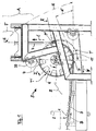
- Fig. 1 is a designated generally A belt conveyor shown with the loose in a conveyor system not shown loose bulk material 1 in a task area 2 on a first circumferentially driven conveyor belt 3 (arrow B, B ') is abandoned.
- Bulk material 1 is then shifted in the conveying direction B to a transition zone Z and covered here by means of a second conveyor belt 4 supplied as shroud.
- the two straps 3, 4 are pressed transversely to the running level E against each other so that the detected bulk material 1 between the two straps 3, 4 can be carried.
- a known per se pressing of the belts introductory buckling station 5 is provided in the transition zone Z a both the loaded strand of the conveyor belt 3 and the above this supplied strand of the shroud 4 detecting roller body 6 is provided.
- the two straps 3, 4 can be brought into superimposition so that at least respective side edge regions 7, 8 (FIG. Fig. 2 ) can be pressed onto one another in a closed position and the bulk material 1 located in the middle region of the straps can be covered such that the conveying strand T formed in this conveying phase can be moved in multiple layers in the direction of the conveying path F (arrow C).
- This construction with the only one roller body 6 to initiate a steep promotion provides that the two supplied runs of conveyor belt 3 and shroud 4 are simultaneously tensioned and deflected.
- the buckling station 4 with the roller body 6 can also be arranged in the region of a transfer zone located above the steep portion of the conveying section F transfer zone and here the shroud 4 lifted off the conveyor belt 3 becomes. This rationalsituation with cooperating in reverse functional position components will not be described in detail.
- the two straps 3, 4 are tuned so that at least one of the two supplied runs by a radial formation a receiving space 9 (FIG. Fig. 2 ) can form 1 for the bulk material, in which case the formation of the receiving space 9 is shown by the shroud 4 here. It is also conceivable that by a corresponding additional assembly (not shown) in the region of the conveying T outboard conveyor belt 3 is partially removed to the outside and thus a receiving space by opposite radial displacement of a portion of the conveyor belt 3 is formed.
- the roller body 6 in its longitudinally central region on both sides of the median plane M has a receiving zone 10 into which a formed by the detected bulk material 1 in the transition zone Z and radially inwardly projecting portion of the shroud 4 is pressed ( Fig. 2 , Sectional view).
- FIG. 1 illustrates that the roller body 6, starting from the region P to the region P 'of the conveying strand T in a quarter circle forming arc contour is included, such that this driving portion 11 causes a 90 ° deflection (angle N) of the conveying T.
- angle N the degree of the conveying direction of the conveying T.
- a conveying direction extending beyond the 90 ° deflection in the manner of a so-called vertical turn (not shown) which clearly shows that the folding station 5 can also be adapted to largely any conveyor systems with an S and / or C-shaped deflection ,
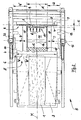
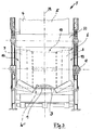
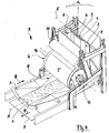
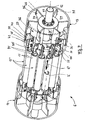
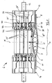
- Fig. 2 to 4 illustrates that the roller body 6 in the direction of its longitudinal axis 12 has two side portions 7, 8 of the shroud 4 and the conveying strand T cross bearing cylinder 13, 14 and in the direction of the longitudinal axis 12 between these two support cylinders 13, 14 a receiving zone 10 defining space is provided, in which the above-described radial formation or the receiving space 9 of the conveying T is pressed.
- This receiving zone 10 is in its the distance of the support cylinder 13, 14 corresponding length A 'characterized variable that the two substantially equal length U, U' having support cylinder 13 and 14 in the direction of the longitudinal axis 12 are displaceable or adjustable ( Fig. 2 ; Arrow D, D ').
- the partially sectioned view according to Fig. 2 also illustrates that the roller body 6 in the region of the receiving zone 10 with at least one at least partially covering them and on the delivery T in the region of the radial formation or the receiving space 9 a radial support force G causing counter-member 15 is provided.
- the counter element 15 '( Fig. 2 , Cutout, left side) as a receiving zone 10 in the longitudinal and circumferential direction completely covering and made of an elastically deformable material existing hose jacket 16 may be formed, which is not part of the invention.
- first pressing phase ( Fig. 1 , Trum T ') is one width W ( Fig. 2 ) having shroud 4 after the guide on an upper roller 33 in an arcuate Zuglasstrum T 'already in the region of the receiving zone 10 and is also loaded radially by the belt tension of the system.
- the shroud 4 is in the strand T 'in a transforming area (dashed line W', Fig. 2 ) is pressed onto the counter element 15, so that a mouth-like receiving contour is already formed in front of the connection region P ( Fig. 3 ) and the receiving process for the bulk material 1 is optimally executable.
- a further embodiment of the roller body 6 is shown, which as the counter member 15 "in the region of the receiving zone 10 has a plurality of extending between the two support cylinders 13 and 14 spring elements 17.
- These spring elements 17 are formed in an expedient design as coil springs 18 which in the Support cylinder 13, 14 at a respective connected thereto and extending radially to the longitudinal axis 12 toward Support disk 19, 20 are held. Since the roller body 6 is constructed substantially mirror-inverted to the longitudinal center plane M, the corresponding arrangement of the components results from the drawings, without describing each in detail.
- the coil springs 18 are held by respective the support plate 19, 20 by cross-screws.
- the connecting hooks 22 of the coil springs 18 engage in respective eyelets 23 of the adjusting screws 21 so that the coil springs 18 are pivotally movable in the pretensioned installation position (arrow Q).
- the springs 18 both in the radial direction (arrow R) moved to the above recording zone 10 as well as the movement arrow Q are pivoted about its longitudinal central axis L.
- this pressing phase of the shroud 4 at the same time corresponding to the spring characteristic effective counterforce G is generated and disadvantageously high speed differences of the two different diameters on the roller body having straps 3 and 4 are thus avoided.
- the diameter of the roller body 6 and known pulleys with a much smaller diameter the lower speed difference of the straps on the roller body 6 can be determined so that it has significantly lower frictional loads.
- the support sleeve 25 is provided with a holder 27 generally designated. With this holder 27, a complete clamping adjustment of all of the coil springs 18 as a kit is possible.
- the holder 27 has a holding plate 28 which rests against a holding projection 29 of the longitudinal axis 12 and cooperates via adjusting screws 30 with a fixed both on the support cylinder 13, 14 and on the support sleeve 25 outer adjusting disc 31.
- corresponding thrust load (arrow H ') of the support sleeve 25 for example by one of the screws 30 and 32, the coil springs 18 are relaxed in the direction of the central longitudinal plane M.
- a reverse pulling movement (arrow H)
- the bias of the coil springs 18 is increased.
- the above-described steep belt conveyor A is formed in the region of the buckling station 5 so that an efficient deflection of the conveyor belts 3, 4 from the horizontal to the vertical is possible in the manner of a Doppelgurt-vertical conveyor and this deflection can also take place from the vertical to the horizontal (not shown).
- the bulk material 1 is frictionally between the two conveyor belts 3, 4 transported upwards, wherein the side edge regions 7, 8 are effective as respective sealing surfaces.
- the effective as a bending and tail pulley roller body 6 allows a gentle deflection of the bulk material 1, wherein the unintentional displacement in the edge regions 7, 8 is avoided even in the rising region F.
- the two arranged in the manner of axially displaceable drum shells bearing cylinder 13, 14 are designed with a diameter of 800 mm.
- the in the initial state in the support zone 10 of the same diameter extending and acting as radial compensators spring elements 17 were pressed in the region of loaded with bulk material 1 conveying T up to a diameter of about 600 mm radially inward.
- the two support cylinders 13 and 14 are arranged in the delivery phase as fixed in the direction of the longitudinal axis 12 assemblies and only by using the elasticity in the region of the spring elements 15, 15 ', 15 "is already achieved a gurtschonende deflection.
- the bulk material 1 in the deflection phase (conveying strand T) is only moved once with respect to the two belt surfaces, whereby damage to the conveyor belts 3, 4 caused by sharp-edged or large-volume material pieces is avoided by the above-described elastic compensation.
- the bulk material 1 or inclusions contained therein can in the direction of effective as a free space receiving zone 10 or against the elastic counter-member 15, 15 ', 15 "dodge and at the same time provided by this counter-member of the shroud 4 conveyor belt is supported so that its running properties not are impaired.
- respective guide profiles 13 'and 14' are provided with the center longitudinal plane M directed inclination to the two support cylinders 13, so that a uniform and edge-free guidance of the bead zone of the shroud 4 is achieved in this pressing area.
- FIG. 7 to 11 Further variants of the roller body 6 or its individual parts are shown, wherein a second embodiment of holders is provided for the spring elements 17 'provided as counter-members 15 " Fig. 5 and 6 support disks 19, 20 shown as a holder, the connection of the distributed over the circumference of the receiving zone 10 spring elements 17 'to a two-part support sleeve 25' out (which in turn is held on the longitudinal axis 12) now by means of in Fig. 9 to 11 shown items.
- the mirror-image held to the center plane M spring elements 17 ' are each end with at least one support hook 35 ( Fig. 10 ) and in the manner of spokes on the cylindrical interior of the support cylinder 13, 14 distributed holding plates 36 are connected. It is also conceivable to provide the contour of the holding plate 36 with a hook-shaped projection, so that a one-piece "spoke” construction is achieved (not shown) and at this the spring elements 17 'directly attack.
- the holding plates 36 are provided with an additional, in cross section U-shaped intermediate part 37, wherein at the respective free legs 38, 39 of the support hooks 35 is held.
- a base leg 40 of the U-shaped intermediate part 37 is in particular via a welded connection at 40 '(FIG. Fig. 7 ) connected to the holding plate 36.
- Fig. 9 is the intermediate part 37 shown as a plate-shaped output part, the legs 38, 39 in the region of bending lines 38 ', 39' to the provided in the installation position U-shape ( Fig. 7 ) are bent over.
- the respective carrying hook 35 has a counterpart 41 (in the form of an eyelet or the like).
- Fig. 7 of the spring element 17 'receiving receiving contour 42 ( Fig. 10 ) on.
- the connection structure is optimized so that in working position of the roller body 6 (FIG. Fig. 8 ) an end-side movement of the spring elements 17 'under the action of the pressing or tensile force (arrow R, Q, Q ") friction with the support structure of the roller body 6 can be introduced.
- the enlarged detail of the support hook 35 according to Fig. 10 illustrates that with the receiving contour 42 a particular for a rolling movement (arrow S ') of the counter member 41 suitable support track S is given and thus in this highly loaded area rapid wear, for example, by selective sliding friction, can be avoided.
- the carrying hook 35 is additionally manufactured from a particularly wear-resistant material.
- threaded connections 43 are advantageously provided, so that with little effort, an exchange of the support hook 35 and the spring elements 17 'is possible.
- spoke construction can be adapted to different diameters or lengths of the roller body 6 or varying spring elements 17 'by appropriate dimensioning of the individual parts 35, 36, 37.
Landscapes
- Engineering & Computer Science (AREA)
- Mechanical Engineering (AREA)
- Structure Of Belt Conveyors (AREA)
Description
Die Erfindung betrifft einen Steilbandförderer für loses Schüttgut gemäß dem Oberbegriff des Anspruchs 1.The invention relates to a steep belt conveyor for loose bulk material according to the preamble of
Bei bekannten Steilbandförderern (
In dieser Übergangszone werden die beiden gegenüberliegenden Trums der Gurte durch ober- bzw. unterseitige Andrückelemente zusammengepreßt, so daß das im wesentlichen mittig geförderte Schüttgut in einem randseitig dichten Aufnahmeraum gehalten ist, gegen seitlichen Austritt gesichert wird und nach Erreichen eines höher gelegenen Abgabeortes ausgefördert werden kann. Durch eine Vielzahl von Andrückelementen und damit einhergehende Gurtbelastungen durch mehrere Deformationszonen ist die Standzeit der Fördergurte bei bekannten Steilbandförderern nachteilig beeinflußt. In
Die Erfindung befaßt sich mit dem Problem, einen Steilbandförderer für loses Schüttgut zu schaffen, dessen Bauteile im Bereich der Übergangszone mit geringem konstruktivem Aufwand eine vollständige Abdeckung von Schüttgütern variabler Konsistenz gewährleisten und dabei durch geringe Reib- und Deformationsbelastungen eine Erhöhung der Standzeit der Gurte möglich ist.The invention is concerned with the problem of creating a steep belt conveyor for loose bulk material whose components in the transition zone with little design effort to ensure complete coverage of bulk solids variable consistency and thereby increasing the service life of the belts is possible by low friction and deformation loads ,
Die Erfindung löst diese Aufgabe mit einem Steilbandförderer mit den Merkmalen des Anspruchs 1. Hinsichtlich wesentlicher weiterer Ausgestaltungen wird auf die Ansprüche 2 bis 12 verwiesen.The invention solves this problem with a steep belt conveyor with the features of
Der Steilbandförderer ist im Bereich der Übergangszone mit lediglich einem Walzenkörper versehen, der als zentrales Element einer in ein Fördersystem integrierbaren Knickstation angeordnet ist, so daß mit vorteilhaft wenigen Bauteilen eine kompakte Funktionsbaugruppe erreicht ist. Dieser Walzenkörper ist in der Knickstation beim Aufnehmen des Schüttgutes nach Art einer Schließrolle wirksam, mit der insbesondere das im Querschnitt maulförmig umformbare Deckband randseitig auf den unter diesem zugeführten Fördergurt aufgepreßt wird.The steep belt conveyor is provided in the region of the transition zone with only one roller body, which is arranged as a central element of an integratable into a conveyor system buckling station, so that advantageously a few components, a compact functional assembly is achieved. This roller body is effective in the buckling station when receiving the bulk material in the manner of a closing roller, with the particular in the cross-sectionally umformbare shroud edge is pressed onto the under this supplied conveyor belt.
Bei dieser Konzeption der Knickstation werden der beladene Trum des Fördergurtes und das oberhalb diesem zugeführte Trum des Deckbandes direkt auf dem Walzenkörper in Übereinanderlage verbracht, gespannt und gleichzeitig umgelenkt. In dieser Verbindungsphase wird das im mittleren Bereich der Gurte aufliegende Schüttgut ohne zusätzliche Andrückelemente gegen randseitigen Austritt gesichert und das ab dieser Phase mehrlagige Fördertrum kann bei seiner in Förderrichtung geneigten Weiterbewegung weitgehend beliebige Neigungs- und/oder Umlenkstellungen einnehmen.In this conception of the buckling station, the loaded strand of the conveyor belt and the strand of the shroud fed in above it are brought directly onto the roll body in superimposition, tensioned and at the same time deflected. In this connection phase, the resting in the central region of the straps bulk material is secured without additional pressure elements against edge leakage and from this phase multi-layer conveyor strand can take largely arbitrary inclination and / or deflection in its inclined in the conveying direction further movement.
Derartige den erfindungsgemäßen Walzenkörper aufweisende Knickstationen sind in kundenspezifisch variabler Konstruktion ausführbar, so daß Förder-Anlagen mit C-förmigen und/oder S-förmigen Gurtführungen möglich sind. Ebenso ist die Anwendung dieses Ein-Walzen-Systems für Vertikalkehren denkbar, bei denen eine Steilförderung mit mehr als 90°-Umlenkung vorgesehen ist.Such the roll body according to the invention having buckling stations are executable in customized variable construction, so that conveyor systems with C-shaped and / or S-shaped belt guides are possible. Likewise, the application of this single-roll system for vertical turning is conceivable in which a steep promotion is provided with more than 90 ° deflection.
Der Walzenkörper ist in Richtung seiner Längsmittelebene umfangsseitig mit mehreren eine belastungsoptimale Mitnahme des Fördertrums bewirkenden Auflagezonen ausgebildet, wobei zwischen zwei den randseitig dichten Preßverbund der beiden Gurte bewirkenden Auflagebereichen mit erfindungsgemäß einstellbaren Auflagezylindern eine mittlere Aufnahmezone für den Bereich des Schüttgut-Stranges vorgesehen ist. Diese Aufnahmezone ist variabel an das Schüttgut anpaßbar, so daß eine durch das strangförmig gepreßte Schüttgut bewirkte und eine radial vorstehende Wulst bildende Ausformung des umgelenkten Deckbandes in diese Aufnahmezone radial verlagerbar ist.The roller body is circumferentially formed in the direction of its longitudinal center plane with several load-optimal entrainment of the conveying strand causing support zones, between two the edge-tight Preßverbund the two straps causing bearing areas with inventively adjustable support cylinders a middle receiving zone for the area of the bulk strand is provided. This receiving zone is variably adaptable to the bulk material, so that one caused by the extruded bulk material and a radially projecting Bead forming shaping of the deflected shroud is radially displaceable in this receiving zone.
Ausgehend von der Bewegungsphase beim Zusammenführen und Übereinanderlegen der beiden Trums wird der dabei radial ausgeformte mittlere Teilbereich des Deckbandes über einen Bogenbereich des Walzenumfangs mitgeführt und der mittlere Wulst-Teil in Folge der Gurtspannung in die Aufnahmezone zwischen den beiden Auflagezylindern eingepreßt. Dabei wird durch ein in der Aufnahmezone dieser Baugruppe vorgesehenes Gegenglied in Form von Federelementen eine Gegenpressung am wulstförmigen Teilbereich erzeugt, derart, daß bei der Umlenkung der Gurte entstehende Geschwindigkeitsdifferenzen, bedingt durch den radialen Abstand von Fördergurt und Deckband, durch das Gegenglied ausgleichbar sind. Damit werden nachteilige Verschleißbelastungen, insbesondere durch sich reibende Oberflächenbereiche oder Walkbewegungen der Gurte, vermieden.Starting from the movement phase when merging and superimposing the two strands of the radially formed middle portion of the shroud over an arc area of the roll circumference is carried along and pressed the middle bead part in consequence of the belt tension in the receiving zone between the two support cylinders. In this case, a counterpressure on the bead-shaped portion is generated by a provided in the receiving zone of this assembly counter-member in the bead-shaped portion, such that in the deflection of the straps resulting speed differences due to the radial distance of the conveyor belt and shroud are compensated by the counterpart. Thus, adverse wear, especially by rubbing surface areas or Walk movements of the straps avoided.
Mit dem - beispielsweise im Vergleich mit bekannten Andruckrollen (
Weitere Einzelheiten und vorteilhafte Ausgestaltungen ergeben sich aus der nachfolgenden Beschreibung und der Zeichnung, in der ein Ausführungsbeispiel des Gegenstands der Erfindung näher veranschaulicht ist. In der Zeichnung zeigen:
- Fig. 1
- eine Seitenansicht einer eine Übergangszone für zwei Gurte bildenden Knickstation eines Steilbandförderers, mit einem direkt als Umlenk- und Preßtrommel wirksamen Walzenkörper,
- Fig. 2
- eine Draufsicht des Steilbandförderers im Bereich der Knickstation gemäß
Fig. 1 , - Fig. 3
- eine Vorderansicht des Steilbandförderers gemäß
Fig. 1 , - Fig. 4
- eine Perspektivdarstellung des Steilbandförderers im Bereich der Knickstation gemäß
Fig. 1 , - Fig. 5
- eine perspektivische Einzeldarstellung des Walzenkörpers der Knickstation gemäß
Fig. 1 , - Fig. 6
- eine Schnittdarstellung des Walzenkörpers gemäß
Fig. 5 , - Fig. 7
- eine teilweise geschnittene Darstellung des Walzenkörpers ähnlich
Fig. 5 mit einer zweiten Ausführung der Halterung der Federelemente, - Fig. 8
- eine Darstellung des Walzenkörpers in der zweiten Ausführung ähnlich
Fig. 6 , und - Fig. 9 bis Fig. 11
- jeweilige Einzeldarstellungen wesentlicher Einzelteile der Halterung gemäß
Fig. 7 und8 .
- Fig. 1
- a side view of a transition zone for two straps forming buckling a steep belt conveyor, with an effective directly as a deflection and pressing drum roller body,
- Fig. 2
- a plan view of the steep belt conveyor in the region of the buckling station according to
Fig. 1 . - Fig. 3
- a front view of the belt conveyor according to
Fig. 1 . - Fig. 4
- a perspective view of the steep belt conveyor in the region of the buckling station according to
Fig. 1 . - Fig. 5
- a perspective detailed representation of the roll body of the buckling station according to
Fig. 1 . - Fig. 6
- a sectional view of the roller body according to
Fig. 5 . - Fig. 7
- a partially sectioned view of the roller body similar
Fig. 5 with a second embodiment of the holder of the spring elements, - Fig. 8
- a representation of the roller body in the second embodiment similar
Fig. 6 , and - Fig. 9 to Fig. 11
- respective individual representations of essential items of the holder according to
Fig. 7 and8th ,
In
Erfindungsgemäß ist eine den an sich bekannten Preßvorgang der Gurte einleitende Knickstation 5 vorgesehen, in deren Übergangszone Z ein sowohl das beladene Trum des Fördergurtes 3 als auch das oberhalb diesem zugeführte Trum des Deckbandes 4 erfassender Walzenkörper 6 vorgesehen ist. Mittels dieses einen Walzenkörpers 6 sind die beiden Gurte 3, 4 in Übereinanderlage verbringbar, damit zumindest jeweilige Seitenrandbereiche 7, 8 (
Es versteht sich, daß die Knickstation 4 mit dem Walzenkörper 6 auch im Bereich einer oberhalb des steilen Teilbereichs der Förderstrecke F befindlichen Übergabezone angeordnet sein kann und hier das Deckband 4 vom Fördergurt 3 abgehoben wird. Diese Fördersituation mit in umgekehrter Funktionslage zusammenwirkenden Bauteilen wird nachfolgend nicht näher beschrieben.It is understood that the buckling
Auf das Spann- und Umlenkungsprinzip mittels des Walzenkörpers 6 sind die beiden Gurte 3, 4 so abgestimmt, daß zumindest einer der beiden zugeführten Trums durch eine radiale Ausformung einen Aufnahmeraum 9 (
In der dargestellten Ausführung des Steilbandförderers A (
Mit dieser zweckmäßigen Ausführung der Knickstation 5 wird deutlich, daß die beiden in einem Verbindungsbereich P am Umfang des Walzenkörpers 6 zusammengeführten Trums der Gurte 3 und 4 in Förderrichtung C einen kreisbogenförmigen Mitnahmebereich 11 auf dem Walzenkörper 6 durchlaufen, dabei das innen liegende Trum des Deckbandes 4 mit dessen radialer Ausformung in die Aufnahmezone 10 des Walzenkörpers 6 verlagert ist und damit das randseitig geschlossene Fördertrum T in einer eine wahlweise Neigung (Winkel N, N';
Die Prinzipdarstellung gemäß
Die Zusammenschau von
Die teilweise geschnittene Darstellung gemäß
In einer am Walzenkörper 6 erfolgenden ersten Preßphase (
In
Die Schraubenfedern 18 sind dabei mittels jeweiliger die Stützscheibe 19, 20 durchgreifender Stellschrauben 21 gehalten. Die Verbindungshaken 22 der Schraubenfedern 18 greifen dabei in jeweilige Ringösen 23 der Stellschrauben 21 so ein, daß die Schraubenfedern 18 auch in vorgespannter Einbaulage schwenkbeweglich sind (Pfeil Q). Bei der vorbeschriebenen Auflage des den Aufnahmeraum 9 bildenden Deckbandes 4 können die Federn 18 sowohl in radialer Richtung (Pfeil R) in die vorbeschriebene Aufnahmezone 10 verlagert als auch entsprechend dem Bewegungspfeil Q um ihre Längsmittelachse L geschwenkt werden. In dieser Preßphase des Deckbandes 4 wird gleichzeitig die entsprechend der Federkennlinie wirksame Gegenkraft G erzeugt und nachteilig hohe Geschwindigkeitsdifferenzen der beiden unterschiedliche Durchmesser auf dem Walzenkörper aufweisenden Gurte 3 und 4 sind damit vermieden. Im Vergleich der Durchmesser des Walzenkörpers 6 und bekannten Umlenkrollen mit wesentlich kleinerem Durchmesser ist die geringere Geschwindigkeitsdifferenz der Gurte auf dem Walzenkörper 6 ermittelbar, so daß diese wesentlich geringere Reibbelastungen aufweist.The coil springs 18 are held by respective the
Die Festlegung der Schraubenfedern 18 mittels der Stellschrauben 21 ist so ausgeführt, daß mittels jeweiliger Einstellungen von Spannmuttern 24 die axiale Vorspannung jeder der Schraubenfedern 18 individuell bemessen werden kann (Pfeil K). Damit ist dieses Gegendrucksystem G auf das Volumen und die Konsistenz des Schüttgutes 1 und die damit geformte Größe des Aufnahmeraumes 9 abstimmbar.The determination of the coil springs 18 by means of the
Diese im Bereich der Stützscheibe 19, 20 gehaltenen Schraubenfedern 18 wirken mit einer die Längsachse 12 umgreifenden Stützhülse 25 dadurch zusammen, daß die außenseitig am Auflagezylinder 13, 14 fixierte Stützscheibe 19 innenseitig mit der Stützhülse 25, beispielsweise mittels einer Schweißverbindung bei 26, verbunden ist. An ihrem außenseitigen Ende ist die Stützhülse 25 mit einer insgesamt mit 27 bezeichneten Halterung versehen. Mit dieser Halterung 27 ist eine komplette Spann-Verstellung sämtlicher der Schraubenfedern 18 als Bausatz möglich.These coil springs 18, which are held in the region of the
Dazu weist die Halterung 27 eine Halteplatte 28 auf, die an einem Halteansatz 29 der Längsachse 12 anliegt und über Stellschrauben 30 mit einer sowohl am Auflagezylinder 13, 14 als auch an der Stützhülse 25 fixierten äußeren Stellscheibe 31 zusammenwirkt. Durch entsprechende Schubbelastung (Pfeil H') der Stützhülse 25, beispielsweise durch eine der Stellschrauben 30 bzw. 32, werden die Schraubenfedern 18 in Richtung der Mittellängsebene M entspannt. Durch eine umgekehrte Zugbewegung (Pfeil H) wird die Vorspannung der Schraubenfedern 18 erhöht.For this purpose, the
Der vorbeschriebene Steilbandförderer A ist im Bereich der Knickstation 5 so ausgebildet, daß nach Art eines Doppelgurt-Senkrechtförderers eine effiziente Umlenkung der Fördergurte 3, 4 aus der Horizontalen in die Senkrechte möglich ist und diese Umlenkung auch aus der Senkrechten in die Horizontale erfolgen kann (nicht dargestellt). Das Schüttgut 1 wird zwischen den beiden Fördergurten 3, 4 kraftschlüssig nach oben transportiert, wobei die Seitenrandbereiche 7, 8 als jeweilige Dichtflächen wirksam werden. Der als eine Knick- und Umlenktrommel wirksame Walzenkörper 6 ermöglicht eine schonende Umlenkung des Schüttgutes 1, wobei dessen ungewollte Verlagerung in die Randbereiche 7, 8 auch im ansteigenden Bereich F sicher vermieden ist.The above-described steep belt conveyor A is formed in the region of the buckling
Bei einem Prototypen des Walzenkörpers 6 sind die beiden nach Art von axial verschiebbaren Trommelmänteln angeordneten Auflagezylinder 13, 14 mit einem Durchmesser von 800 mm ausgeführt. Die im Ausgangszustand in der Auflagezone 10 mit gleichem Durchmesser verlaufenden und als radiale Kompensatoren wirksamen Federelemente 17 wurden im Bereich des mit Schüttgut 1 beladenen Fördertrums T bis auf einen Durchmesser von ca. 600 mm radial nach innen gedrückt. Dabei sind die beiden Auflagezylinder 13 und 14 in der Förderphase als in Richtung der Längsachse 12 feststehende Baugruppen angeordnet und nur durch Nutzung der Elastizität im Bereich der Federelemente 15, 15', 15" wird bereits eine gurtschonende Umlenkung erreicht.In a prototype of the
Denkbar ist auch, die beiden Auflagezylinder 13, 14 permanent axial verschieblich (Pfeil D, D', Fig. 22) auf der Längsachse 12 anzuordnen und beispielsweise mittels des nicht Teil der Erfindung anzusehenden elastisch verformbaren Schlauchmantels 16 zu verbinden. Damit können wechselnde Volumen des Schüttgutes 1 oder darin enthaltene Festkörper durch variable Verschiebung der Zylinder 13 und/oder 14 ausgeglichen werden.It is also conceivable to arrange the two
In jedem Fall wird das Schüttgut 1 in der Umlenkungsphase (Fördertrum T) in Bezug auf die beiden Gurtoberflächen nur einmal bewegt, wobei durch scharfkantige oder großvolumige Materialstücke bedingte Beschädigungen an den Fördergurten 3, 4 durch die vorbeschriebene elastische Kompensation vermieden sind. Das Schüttgut 1 bzw. darin enthaltene Einschlüsse können in Richtung der als Freiraum wirksamen Aufnahmezone 10 bzw. gegen das elastische Gegenglied 15, 15', 15" ausweichen und gleichzeitig wird durch dieses Gegenglied der als Deckband 4 vorgesehene Fördergurt so unterstützt, daß dessen Laufeigenschaften nicht beeinträchtigt sind.In any case, the
Denkbar ist in diesem Zusammenhang auch, die den Freiraum aufweisende Aufnahmezone 10 durch ein nicht zur Erfindung gehörendes, starres Gegenglied zu begrenzen (nicht dargestellt), wobei jedoch für dieses eine zusätzliche separate Lagerung im Bereich der Längsachse 12 notwendig ist. Im Übergangsbereich zwischen den beiden Auflagezylindern 13 und 14 können zur Auflagezone 10 hin scharfkantige Bereiche mit die Fördergurte nachteilig belastender Kerbwirkung entstehen.It is also conceivable in this context to limit the free
In den dargestellten Ausführungen des Walzenkörpers 6 sind an den beiden Auflagezylindern 13, 14 jeweilige Führungsprofile 13' und 14' mit zur Mittellängsebene M gerichteter Neigung vorgesehen, so daß in diesem Preßbereich eine gleichmäßige und kantenfreie Führung der Wulst-Zone des Deckbandes 4 erreicht ist.In the illustrated embodiments of the
Das in zweckmäßiger Ausführung realisierte Konzept mit dem elastischen Kompensator 15, 15', 15" bewirkt im Bereich der Aufnahmezone 10 einen Ausgleich zwischen den beiden durchmesserabhängig unterschiedlichen Umfangsgeschwindigkeiten der Gurte 3 und 4, da das elastische Gegenglied 15, 15', 15" eine radiale Relativbewegung des Deckbandes 4 gegenüber dem mit unveränderter Kontur umlaufenden ersten Fördergurt 3 ausgleichen kann. Nach dem Ablaufen des Fördertrums T von der Umfangsfläche des Walzenkörpers 6 (im Bereich P',
In
Die spiegelbildlich zur Mittelebene M gehaltenen Federelemente 17' sind dabei endseitig jeweils mit zumindest einen Traghaken 35 (
In der dargestellten Ausführung sind die Halteplatten 36 mit einem zusätzlichen, im Querschnitt U-förmigen Zwischenteil 37 versehen, wobei an dessen jeweiligen freien Schenkeln 38, 39 einer der Traghaken 35 gehalten ist. Ein Basisschenkel 40 des U-förmigen Zwischenteils 37 ist insbesondere über eine Schweißverbindung bei 40' (
Bei dieser dreiteiligen Baueinheit 35, 36, 37 weist der jeweilige Traghaken 35 eine das in Form einer Öse o. dgl. ausgebildete Gegenglied 41 (
Die vergrößerte Einzeldarstellung des Traghakens 35 gemäß
Diese einfache Montage und Demontage im Bereich der Federelemente 17' wird noch dadurch begünstigt, daß durch die "Speichen"-Konstruktion jeweilige Freiräume 44 in Längsrichtung des Walzenkörpers 6 gebildet sind und damit die insbesondere lösbar gehaltenen Einzelteile einfach erreichbar sind. In zweckmäßiger Ausführung ist die Halteplatte 36 mit den beiden Stützhülsen 25' jeweils im Bereich von Profilausnehmungen 45, 46 (
Die vorbeschriebene "Speichen"-Konstruktion ist durch entsprechende Dimensionierung der Einzelteile 35, 36, 37 an unterschiedliche Durchmesser bzw. Längen der Walzenkörper 6 bzw. variierende Federelemente 17' anpaßbar. Ebenso ist denkbar, im Bereich der Halteplatten 36 bzw. des am Zwischenteil 37 gehaltenen Traghakens 35 eine radial und/oder axial einstellbare Abstützung (nicht dargestellt) der Federelemente 17'vorzusehen.The above-described "spoke" construction can be adapted to different diameters or lengths of the
Claims (12)
- Steep angle belt conveyor for loose bulk material (1), comprising a first conveyor belt (3) and a second conveyor belt (4) assigned to said first conveyor belt as a cover band, the bulk material (1), which is fed through in a substantially centred manner on the first conveyor belt (3), can be received between the two belts (3, 4) in the region of a transition zone (Z) that is curved in the conveying direction (B), and the two belts (3, 4) being pressed against one another transversely to the running plane (E) in order to transport the bulk material (1) in a steep downstream portion of a conveying path (F), a roll body (6) being provided in the transition zone (Z), which roll body grasps both the loaded side of the conveyor belt (3) and the side of the cover band (4) which is fed above said conveyor belt, at least one of the two sides of the belts (3, 4) that are fed through forming a receiving chamber (9) for the bulk material (1) by means of a radial shaping, the roll body (6) comprising a receiving zone (10) into which a portion of the cover band (4) that projects radially inwards through the grasped bulk material (1) can be moved, the roll body (6) having two support cylinders (13, 14), provided along the longitudinal axle (12) thereof, for supporting the two edge regions of the conveying side (T), said support cylinders defining the receiving zone (10) which receives the radial shaping of the conveying side (T), and the roll body (6) being provided in the region of the receiving zone (10) with at least one counter member (15) which covers at least portions of said receiving zone and which produces a radial supporting force (G) in the region of the radial shaping at least on the multi-layered conveying side (T), characterised in that the roll body (6) comprises a plurality of spring elements (17, 17') extending between the two support cylinders (13, 14), in the region of the receiving zone (10), as the counter member (15").
- Steep angle belt conveyor according to claim 1, characterised in that the roll body (6) comprises a receiving zone (10) that can be adjusted by means of support cylinders (13, 14) which are movable along the longitudinal axle (12) (arrow D, D').
- Steep angle belt conveyor according to either claim 1 or claim 2, characterised in that the spring elements (17), formed as helical springs (18), act in the region of the support cylinders (13, 14) on respective holders that are connected to said support cylinders and are formed as support rings (19, 20).
- Steep angle belt conveyor according to claim 3, characterised in that the helical springs (18) are held by respective adjusting screws (21) passing through the support ring (19, 20) and are pivotably movable (arrow Q) when the cover band (4) is being placed on.
- Steep angle belt conveyor according to either claim 3 or claim 4, characterised in that the helical springs (18) can be tensioned by adjusting screws (21, 30, 32) in the longitudinal direction (arrow H, H').
- Steep angle belt conveyor according to any of claims 3 to 5, characterised in that the support ring (19, 20) of the helical springs (18) cooperates with a support sleeve (25) which surrounds the longitudinal axle (12) and in turn comprises a mounting (27) which is provided for tensioning (arrow H, H') the helical springs (18).
- Steep angle belt conveyor according to claim 6, characterised in that the mounting (27) is provided with a retaining plate (28) having a plurality of radially offset adjusting screws (30) and resting on a retaining lug (29) of the longitudinal axle (12), which retaining plate cooperates with an adjusting disc (31) held on the movable support sleeve (25).
- Steep angle belt conveyor according to any of claims 3 to 7, characterised in that the spring elements (17') provided as counter members (15") are each connected at the end thereof to retaining plates (36) which comprise at least one carrying hook (35) and are distributed over the interior of the support cylinder (13, 14) in the manner of spokes.
- Steep angle belt conveyor according to claim 8, characterised in that in each case two of the carrying hooks (35) are connected to one of the retaining plates (36) respectively via an intermediate (37) part that is U-shaped in cross section.
- Steep angle belt conveyor according to either claim 8 or claim 9, characterised in that the carrying hook (35) comprises a receiving profile (42) which receives the counter member (41), formed as a loop or similar, of the spring element (17') in such a way that, in the operating position of the roll body (6), the movement (arrow Q', Q") at the end of the spring element (17') can be absorbed in a low-friction manner.
- Steep angle belt conveyor according to claim 10, characterised in that a support path (S), which is suitable for a rolling movement of the counter member (41), can be predetermined by means of the receiving profile (42).
- Steep angle belt conveyor according to any of claims 3 to 11, characterised in that an axially and/or radially adjustable support of the spring element (17') is formed in the region of the retaining plates (36).
Priority Applications (3)
| Application Number | Priority Date | Filing Date | Title |
|---|---|---|---|
| PL07725039T PL2016010T3 (en) | 2006-05-11 | 2007-05-09 | Steep angle conveyor for bulk material |
| SI200731769A SI2016010T1 (en) | 2006-05-11 | 2007-05-09 | Steep angle conveyor for bulk material |
| CY20161100351T CY1117444T1 (en) | 2006-05-11 | 2016-04-27 | PROJECTOR LARGE-SLIP BELT PROMOTER |
Applications Claiming Priority (2)
| Application Number | Priority Date | Filing Date | Title |
|---|---|---|---|
| DE202006007637U DE202006007637U1 (en) | 2006-05-11 | 2006-05-11 | Bag conveyor for friable goods has roll body covering both loaded compartment of conveyor belt and cover belt compartments above it |
| PCT/EP2007/004117 WO2007131690A1 (en) | 2006-05-11 | 2007-05-09 | Steep angle conveyor for bulk material |
Publications (2)
| Publication Number | Publication Date |
|---|---|
| EP2016010A1 EP2016010A1 (en) | 2009-01-21 |
| EP2016010B1 true EP2016010B1 (en) | 2016-02-24 |
Family
ID=36934321
Family Applications (1)
| Application Number | Title | Priority Date | Filing Date |
|---|---|---|---|
| EP07725039.7A Active EP2016010B1 (en) | 2006-05-11 | 2007-05-09 | Steep angle conveyor for bulk material |
Country Status (9)
| Country | Link |
|---|---|
| EP (1) | EP2016010B1 (en) |
| CY (1) | CY1117444T1 (en) |
| DE (1) | DE202006007637U1 (en) |
| DK (1) | DK2016010T3 (en) |
| ES (1) | ES2568658T3 (en) |
| HU (1) | HUE027978T2 (en) |
| PL (1) | PL2016010T3 (en) |
| SI (1) | SI2016010T1 (en) |
| WO (1) | WO2007131690A1 (en) |
Families Citing this family (2)
| Publication number | Priority date | Publication date | Assignee | Title |
|---|---|---|---|---|
| DE202006007637U1 (en) * | 2006-05-11 | 2006-08-17 | Vhv Anlagenbau Gmbh | Bag conveyor for friable goods has roll body covering both loaded compartment of conveyor belt and cover belt compartments above it |
| NO2791336T3 (en) | 2015-04-28 | 2018-04-28 |
Family Cites Families (11)
| Publication number | Priority date | Publication date | Assignee | Title |
|---|---|---|---|---|
| IL35062A (en) | 1970-08-05 | 1973-03-30 | Dagon Batey Mamguroth Le Israe | Elevator conveyor for bulk materials |
| JPS51120561A (en) | 1975-04-02 | 1976-10-21 | Allis Chalmers Canada | Cargo work device of bulky material |
| GB2008527B (en) | 1977-09-20 | 1982-03-17 | Carves Simon Ltd | Conveyor for bulk materials |
| IN161455B (en) | 1983-08-17 | 1987-12-05 | Continental Conveyor & Equip | |
| FR2619090B1 (en) | 1987-08-07 | 1990-01-05 | Mareau Dominique | BULK LIFT |
| EP0417363B1 (en) | 1989-09-15 | 1992-10-14 | Kabushiki Kaisha Iseki Kaihatsu Koki | Vertical type conveyor |
| JPH04358608A (en) | 1991-02-08 | 1992-12-11 | Bridgestone Corp | Belt conveyer device |
| JPH06329227A (en) | 1993-05-24 | 1994-11-29 | Bridgestone Corp | Belt conveyor device |
| DE29717996U1 (en) | 1997-10-13 | 1999-02-11 | VHV Anlagenbau GmbH, 48477 Hörstel | Belt conveyor |
| US6484870B2 (en) | 2000-06-14 | 2002-11-26 | John N. Bohnker | Dual belt conveyor system |
| DE202006007637U1 (en) * | 2006-05-11 | 2006-08-17 | Vhv Anlagenbau Gmbh | Bag conveyor for friable goods has roll body covering both loaded compartment of conveyor belt and cover belt compartments above it |
-
2006
- 2006-05-11 DE DE202006007637U patent/DE202006007637U1/en not_active Expired - Lifetime
-
2007
- 2007-05-09 ES ES07725039.7T patent/ES2568658T3/en active Active
- 2007-05-09 EP EP07725039.7A patent/EP2016010B1/en active Active
- 2007-05-09 WO PCT/EP2007/004117 patent/WO2007131690A1/en not_active Ceased
- 2007-05-09 PL PL07725039T patent/PL2016010T3/en unknown
- 2007-05-09 DK DK07725039.7T patent/DK2016010T3/en active
- 2007-05-09 HU HUE07725039A patent/HUE027978T2/en unknown
- 2007-05-09 SI SI200731769A patent/SI2016010T1/en unknown
-
2016
- 2016-04-27 CY CY20161100351T patent/CY1117444T1/en unknown
Also Published As
| Publication number | Publication date |
|---|---|
| SI2016010T1 (en) | 2016-06-30 |
| DE202006007637U1 (en) | 2006-08-17 |
| DK2016010T3 (en) | 2016-05-09 |
| CY1117444T1 (en) | 2017-04-26 |
| PL2016010T3 (en) | 2016-08-31 |
| EP2016010A1 (en) | 2009-01-21 |
| ES2568658T3 (en) | 2016-05-03 |
| HUE027978T2 (en) | 2016-11-28 |
| WO2007131690A1 (en) | 2007-11-22 |
Similar Documents
| Publication | Publication Date | Title |
|---|---|---|
| DE3326688C2 (en) | ||
| EP2289822B1 (en) | Support device for conveying heavy loads | |
| EP2289823B1 (en) | Support device for a conveyor and method for operating said conveyor | |
| EP2676902B1 (en) | Curve roller conveyor with conveyor section bearing element | |
| EP3078543B1 (en) | Vehicle for the transport of bulk and/or piece goods | |
| DE19738909B4 (en) | Expandable shaft and this having tape winding device | |
| DE3421413C2 (en) | ||
| WO2007131690A1 (en) | Steep angle conveyor for bulk material | |
| DE102022102695A1 (en) | belt curve | |
| DE3247625C2 (en) | Clamping device for scraper floors or similar transport floors on agricultural vehicles and machines | |
| WO2008116707A1 (en) | Radial roller bearing | |
| WO1997029983A2 (en) | Apron conveyor | |
| EP3088336B1 (en) | Belt conveyor device for transporting objects, in particular bulk material | |
| EP3621901A1 (en) | Conveying device having two conveying carts and cover for covering a space between the two conveying carts | |
| DE102024103468B4 (en) | Swivel cradle bearing | |
| DE2839183A1 (en) | CONNECTOR FOR THE IDLE ROLLERS OF A CONVEYOR WITH CATENARY BAND | |
| DE29717996U1 (en) | Belt conveyor | |
| DE10040874C2 (en) | Curve conveyor for conveying piece goods on an endless conveyor belt along an arc length | |
| DE19803498C2 (en) | Storage unit | |
| EP2489611A1 (en) | Conveyor device with a powered endless pulling instrument for articles from the tobacco processing industry | |
| EP3173261B1 (en) | Anti-slip device with one traction member guided over the tread area within a chain strand and rigid holding body | |
| DE1574418C (en) | Guide device for moving material webs | |
| DE202014101099U1 (en) | commercial vehicle | |
| EP1975095B1 (en) | Separator | |
| AT281509B (en) | Drive pulley for ropes or chains |
Legal Events
| Date | Code | Title | Description |
|---|---|---|---|
| PUAI | Public reference made under article 153(3) epc to a published international application that has entered the european phase |
Free format text: ORIGINAL CODE: 0009012 |
|
| 17P | Request for examination filed |
Effective date: 20081118 |
|
| AK | Designated contracting states |
Kind code of ref document: A1 Designated state(s): AT BE BG CH CY CZ DE DK EE ES FI FR GB GR HU IE IS IT LI LT LU LV MC MT NL PL PT RO SE SI SK TR |
|
| AX | Request for extension of the european patent |
Extension state: AL BA HR MK RS |
|
| 17Q | First examination report despatched |
Effective date: 20110523 |
|
| DAX | Request for extension of the european patent (deleted) | ||
| GRAP | Despatch of communication of intention to grant a patent |
Free format text: ORIGINAL CODE: EPIDOSNIGR1 |
|
| INTG | Intention to grant announced |
Effective date: 20150925 |
|
| GRAS | Grant fee paid |
Free format text: ORIGINAL CODE: EPIDOSNIGR3 |
|
| GRAA | (expected) grant |
Free format text: ORIGINAL CODE: 0009210 |
|
| AK | Designated contracting states |
Kind code of ref document: B1 Designated state(s): AT BE BG CH CY CZ DE DK EE ES FI FR GB GR HU IE IS IT LI LT LU LV MC MT NL PL PT RO SE SI SK TR |
|
| REG | Reference to a national code |
Ref country code: GB Ref legal event code: FG4D Free format text: NOT ENGLISH |
|
| REG | Reference to a national code |
Ref country code: CH Ref legal event code: EP |
|
| REG | Reference to a national code |
Ref country code: AT Ref legal event code: REF Ref document number: 776568 Country of ref document: AT Kind code of ref document: T Effective date: 20160315 |
|
| REG | Reference to a national code |
Ref country code: IE Ref legal event code: FG4D Free format text: LANGUAGE OF EP DOCUMENT: GERMAN |
|
| REG | Reference to a national code |
Ref country code: CH Ref legal event code: NV Representative=s name: SCHNEIDER FELDMANN AG PATENT- UND MARKENANWAEL, CH |
|
| REG | Reference to a national code |
Ref country code: DE Ref legal event code: R096 Ref document number: 502007014576 Country of ref document: DE |
|
| PGFP | Annual fee paid to national office [announced via postgrant information from national office to epo] |
Ref country code: MC Payment date: 20160323 Year of fee payment: 10 |
|
| REG | Reference to a national code |
Ref country code: ES Ref legal event code: FG2A Ref document number: 2568658 Country of ref document: ES Kind code of ref document: T3 Effective date: 20160503 Ref country code: RO Ref legal event code: EPE |
|
| REG | Reference to a national code |
Ref country code: DK Ref legal event code: T3 Effective date: 20160503 |
|
| REG | Reference to a national code |
Ref country code: EE Ref legal event code: FG4A Ref document number: E011700 Country of ref document: EE Effective date: 20160405 |
|
| REG | Reference to a national code |
Ref country code: SE Ref legal event code: TRGR |
|
| REG | Reference to a national code |
Ref country code: PT Ref legal event code: SC4A Free format text: AVAILABILITY OF NATIONAL TRANSLATION Effective date: 20160516 |
|
| REG | Reference to a national code |
Ref country code: NL Ref legal event code: FP |
|
| REG | Reference to a national code |
Ref country code: FR Ref legal event code: PLFP Year of fee payment: 10 |
|
| PGFP | Annual fee paid to national office [announced via postgrant information from national office to epo] |
Ref country code: CY Payment date: 20160427 Year of fee payment: 10 Ref country code: FI Payment date: 20160405 Year of fee payment: 10 |
|
| REG | Reference to a national code |
Ref country code: SK Ref legal event code: T3 Ref document number: E 20919 Country of ref document: SK |
|
| REG | Reference to a national code |
Ref country code: GR Ref legal event code: EP Ref document number: 20160400776 Country of ref document: GR Effective date: 20160601 |
|
| REG | Reference to a national code |
Ref country code: DE Ref legal event code: R097 Ref document number: 502007014576 Country of ref document: DE |
|
| REG | Reference to a national code |
Ref country code: HU Ref legal event code: AG4A Ref document number: E027978 Country of ref document: HU |
|
| PLBE | No opposition filed within time limit |
Free format text: ORIGINAL CODE: 0009261 |
|
| STAA | Information on the status of an ep patent application or granted ep patent |
Free format text: STATUS: NO OPPOSITION FILED WITHIN TIME LIMIT |
|
| 26N | No opposition filed |
Effective date: 20161125 |
|
| REG | Reference to a national code |
Ref country code: FR Ref legal event code: PLFP Year of fee payment: 11 |
|
| PG25 | Lapsed in a contracting state [announced via postgrant information from national office to epo] |
Ref country code: FI Free format text: LAPSE BECAUSE OF NON-PAYMENT OF DUE FEES Effective date: 20170509 Ref country code: MC Free format text: LAPSE BECAUSE OF NON-PAYMENT OF DUE FEES Effective date: 20170531 |
|
| PG25 | Lapsed in a contracting state [announced via postgrant information from national office to epo] |
Ref country code: CY Free format text: LAPSE BECAUSE OF NON-PAYMENT OF DUE FEES Effective date: 20170509 |
|
| REG | Reference to a national code |
Ref country code: FR Ref legal event code: PLFP Year of fee payment: 12 |
|
| PG25 | Lapsed in a contracting state [announced via postgrant information from national office to epo] |
Ref country code: MT Free format text: LAPSE BECAUSE OF FAILURE TO SUBMIT A TRANSLATION OF THE DESCRIPTION OR TO PAY THE FEE WITHIN THE PRESCRIBED TIME-LIMIT Effective date: 20160224 Ref country code: IS Free format text: LAPSE BECAUSE OF FAILURE TO SUBMIT A TRANSLATION OF THE DESCRIPTION OR TO PAY THE FEE WITHIN THE PRESCRIBED TIME-LIMIT Effective date: 20160224 |
|
| REG | Reference to a national code |
Ref country code: CH Ref legal event code: PFA Owner name: VHV ANLAGENBAU GMBH, DE Free format text: FORMER OWNER: VHV ANLAGENBAU GMBH, DE |
|
| PGFP | Annual fee paid to national office [announced via postgrant information from national office to epo] |
Ref country code: LT Payment date: 20220321 Year of fee payment: 16 Ref country code: BG Payment date: 20220310 Year of fee payment: 16 |
|
| PGFP | Annual fee paid to national office [announced via postgrant information from national office to epo] |
Ref country code: SK Payment date: 20220317 Year of fee payment: 16 Ref country code: PT Payment date: 20220309 Year of fee payment: 16 Ref country code: LV Payment date: 20220309 Year of fee payment: 16 Ref country code: GR Payment date: 20220309 Year of fee payment: 16 Ref country code: EE Payment date: 20220309 Year of fee payment: 16 |
|
| PGFP | Annual fee paid to national office [announced via postgrant information from national office to epo] |
Ref country code: SE Payment date: 20220531 Year of fee payment: 16 Ref country code: RO Payment date: 20220406 Year of fee payment: 16 Ref country code: LU Payment date: 20220516 Year of fee payment: 16 Ref country code: IE Payment date: 20220421 Year of fee payment: 16 |
|
| PGFP | Annual fee paid to national office [announced via postgrant information from national office to epo] |
Ref country code: SI Payment date: 20220309 Year of fee payment: 16 |
|
| REG | Reference to a national code |
Ref country code: LT Ref legal event code: MM4D Effective date: 20230509 |
|
| REG | Reference to a national code |
Ref country code: EE Ref legal event code: MM4A Ref document number: E011700 Country of ref document: EE Effective date: 20230531 |
|
| REG | Reference to a national code |
Ref country code: SK Ref legal event code: MM4A Ref document number: E 20919 Country of ref document: SK Effective date: 20230509 |
|
| REG | Reference to a national code |
Ref country code: SE Ref legal event code: EUG |
|
| PG25 | Lapsed in a contracting state [announced via postgrant information from national office to epo] |
Ref country code: SK Free format text: LAPSE BECAUSE OF NON-PAYMENT OF DUE FEES Effective date: 20230509 |
|
| PG25 | Lapsed in a contracting state [announced via postgrant information from national office to epo] |
Ref country code: GR Free format text: LAPSE BECAUSE OF NON-PAYMENT OF DUE FEES Effective date: 20231208 |
|
| PG25 | Lapsed in a contracting state [announced via postgrant information from national office to epo] |
Ref country code: SK Free format text: LAPSE BECAUSE OF NON-PAYMENT OF DUE FEES Effective date: 20230509 Ref country code: SI Free format text: LAPSE BECAUSE OF NON-PAYMENT OF DUE FEES Effective date: 20230510 Ref country code: SE Free format text: LAPSE BECAUSE OF NON-PAYMENT OF DUE FEES Effective date: 20230510 Ref country code: RO Free format text: LAPSE BECAUSE OF NON-PAYMENT OF DUE FEES Effective date: 20230509 Ref country code: PT Free format text: LAPSE BECAUSE OF NON-PAYMENT OF DUE FEES Effective date: 20231109 Ref country code: LV Free format text: LAPSE BECAUSE OF NON-PAYMENT OF DUE FEES Effective date: 20230509 Ref country code: LU Free format text: LAPSE BECAUSE OF NON-PAYMENT OF DUE FEES Effective date: 20230509 Ref country code: LT Free format text: LAPSE BECAUSE OF NON-PAYMENT OF DUE FEES Effective date: 20230509 Ref country code: GR Free format text: LAPSE BECAUSE OF NON-PAYMENT OF DUE FEES Effective date: 20231208 Ref country code: EE Free format text: LAPSE BECAUSE OF NON-PAYMENT OF DUE FEES Effective date: 20230531 |
|
| REG | Reference to a national code |
Ref country code: IE Ref legal event code: MM4A |
|
| REG | Reference to a national code |
Ref country code: SI Ref legal event code: KO00 Effective date: 20240222 |
|
| PG25 | Lapsed in a contracting state [announced via postgrant information from national office to epo] |
Ref country code: IE Free format text: LAPSE BECAUSE OF NON-PAYMENT OF DUE FEES Effective date: 20230509 |
|
| PG25 | Lapsed in a contracting state [announced via postgrant information from national office to epo] |
Ref country code: IE Free format text: LAPSE BECAUSE OF NON-PAYMENT OF DUE FEES Effective date: 20230509 |
|
| PGFP | Annual fee paid to national office [announced via postgrant information from national office to epo] |
Ref country code: CZ Payment date: 20240325 Year of fee payment: 18 |
|
| PGFP | Annual fee paid to national office [announced via postgrant information from national office to epo] |
Ref country code: TR Payment date: 20240318 Year of fee payment: 18 Ref country code: PL Payment date: 20240315 Year of fee payment: 18 |
|
| PGFP | Annual fee paid to national office [announced via postgrant information from national office to epo] |
Ref country code: NL Payment date: 20240524 Year of fee payment: 18 |
|
| PGFP | Annual fee paid to national office [announced via postgrant information from national office to epo] |
Ref country code: GB Payment date: 20240513 Year of fee payment: 18 |
|
| PGFP | Annual fee paid to national office [announced via postgrant information from national office to epo] |
Ref country code: DK Payment date: 20240415 Year of fee payment: 18 |
|
| PGFP | Annual fee paid to national office [announced via postgrant information from national office to epo] |
Ref country code: ES Payment date: 20240603 Year of fee payment: 18 |
|
| PGFP | Annual fee paid to national office [announced via postgrant information from national office to epo] |
Ref country code: AT Payment date: 20240513 Year of fee payment: 18 |
|
| PGFP | Annual fee paid to national office [announced via postgrant information from national office to epo] |
Ref country code: IT Payment date: 20240509 Year of fee payment: 18 Ref country code: FR Payment date: 20240527 Year of fee payment: 18 |
|
| PGFP | Annual fee paid to national office [announced via postgrant information from national office to epo] |
Ref country code: HU Payment date: 20240322 Year of fee payment: 18 Ref country code: BE Payment date: 20240528 Year of fee payment: 18 |
|
| PG25 | Lapsed in a contracting state [announced via postgrant information from national office to epo] |
Ref country code: BG Free format text: LAPSE BECAUSE OF NON-PAYMENT OF DUE FEES Effective date: 20230509 |
|
| PG25 | Lapsed in a contracting state [announced via postgrant information from national office to epo] |
Ref country code: BG Free format text: LAPSE BECAUSE OF NON-PAYMENT OF DUE FEES Effective date: 20230509 |
|
| PGFP | Annual fee paid to national office [announced via postgrant information from national office to epo] |
Ref country code: DE Payment date: 20250415 Year of fee payment: 19 |
|
| PGFP | Annual fee paid to national office [announced via postgrant information from national office to epo] |
Ref country code: CH Payment date: 20250601 Year of fee payment: 19 |
|
| REG | Reference to a national code |
Ref country code: DK Ref legal event code: EBP Effective date: 20250531 |
|
| REG | Reference to a national code |
Ref country code: NL Ref legal event code: MM Effective date: 20250601 |
|
| PG25 | Lapsed in a contracting state [announced via postgrant information from national office to epo] |
Ref country code: AT Free format text: LAPSE BECAUSE OF NON-PAYMENT OF DUE FEES Effective date: 20250509 |
|
| PG25 | Lapsed in a contracting state [announced via postgrant information from national office to epo] |
Ref country code: HU Free format text: LAPSE BECAUSE OF NON-PAYMENT OF DUE FEES Effective date: 20250510 |
|
| REG | Reference to a national code |
Ref country code: AT Ref legal event code: MM01 Ref document number: 776568 Country of ref document: AT Kind code of ref document: T Effective date: 20250509 |
|
| PG25 | Lapsed in a contracting state [announced via postgrant information from national office to epo] |
Ref country code: CZ Free format text: LAPSE BECAUSE OF NON-PAYMENT OF DUE FEES Effective date: 20250509 |
|
| GBPC | Gb: european patent ceased through non-payment of renewal fee |
Effective date: 20250509 |
|
| REG | Reference to a national code |
Ref country code: BE Ref legal event code: MM Effective date: 20250531 |
|
| PG25 | Lapsed in a contracting state [announced via postgrant information from national office to epo] |
Ref country code: NL Free format text: LAPSE BECAUSE OF NON-PAYMENT OF DUE FEES Effective date: 20250601 |
|
| PG25 | Lapsed in a contracting state [announced via postgrant information from national office to epo] |
Ref country code: GB Free format text: LAPSE BECAUSE OF NON-PAYMENT OF DUE FEES Effective date: 20250509 |
|
| PG25 | Lapsed in a contracting state [announced via postgrant information from national office to epo] |
Ref country code: DK Free format text: LAPSE BECAUSE OF NON-PAYMENT OF DUE FEES Effective date: 20250531 |
|
| PG25 | Lapsed in a contracting state [announced via postgrant information from national office to epo] |
Ref country code: BE Free format text: LAPSE BECAUSE OF NON-PAYMENT OF DUE FEES Effective date: 20250531 Ref country code: IT Free format text: LAPSE BECAUSE OF NON-PAYMENT OF DUE FEES Effective date: 20250509 |
|
| PG25 | Lapsed in a contracting state [announced via postgrant information from national office to epo] |
Ref country code: FR Free format text: LAPSE BECAUSE OF NON-PAYMENT OF DUE FEES Effective date: 20250531 |