EP2015976B1 - Foldable and height-adjustable stroller - Google Patents
Foldable and height-adjustable stroller Download PDFInfo
- Publication number
- EP2015976B1 EP2015976B1 EP07783604A EP07783604A EP2015976B1 EP 2015976 B1 EP2015976 B1 EP 2015976B1 EP 07783604 A EP07783604 A EP 07783604A EP 07783604 A EP07783604 A EP 07783604A EP 2015976 B1 EP2015976 B1 EP 2015976B1
- Authority
- EP
- European Patent Office
- Prior art keywords
- seat
- stroller
- frame
- linkage
- assembly
- Prior art date
- Legal status (The legal status is an assumption and is not a legal conclusion. Google has not performed a legal analysis and makes no representation as to the accuracy of the status listed.)
- Expired - Fee Related
Links
Images


Classifications
-
- B—PERFORMING OPERATIONS; TRANSPORTING
- B62—LAND VEHICLES FOR TRAVELLING OTHERWISE THAN ON RAILS
- B62B—HAND-PROPELLED VEHICLES, e.g. HAND CARTS OR PERAMBULATORS; SLEDGES
- B62B7/00—Carriages for children; Perambulators, e.g. dolls' perambulators
- B62B7/04—Carriages for children; Perambulators, e.g. dolls' perambulators having more than one wheel axis; Steering devices therefor
- B62B7/06—Carriages for children; Perambulators, e.g. dolls' perambulators having more than one wheel axis; Steering devices therefor collapsible or foldable
- B62B7/08—Carriages for children; Perambulators, e.g. dolls' perambulators having more than one wheel axis; Steering devices therefor collapsible or foldable in the direction of, or at right angles to, the wheel axis
-
- B—PERFORMING OPERATIONS; TRANSPORTING
- B62—LAND VEHICLES FOR TRAVELLING OTHERWISE THAN ON RAILS
- B62B—HAND-PROPELLED VEHICLES, e.g. HAND CARTS OR PERAMBULATORS; SLEDGES
- B62B7/00—Carriages for children; Perambulators, e.g. dolls' perambulators
- B62B7/04—Carriages for children; Perambulators, e.g. dolls' perambulators having more than one wheel axis; Steering devices therefor
- B62B7/06—Carriages for children; Perambulators, e.g. dolls' perambulators having more than one wheel axis; Steering devices therefor collapsible or foldable
- B62B7/062—Coupling unit between front wheels, rear wheels and handle
-
- B—PERFORMING OPERATIONS; TRANSPORTING
- B62—LAND VEHICLES FOR TRAVELLING OTHERWISE THAN ON RAILS
- B62B—HAND-PROPELLED VEHICLES, e.g. HAND CARTS OR PERAMBULATORS; SLEDGES
- B62B7/00—Carriages for children; Perambulators, e.g. dolls' perambulators
- B62B7/04—Carriages for children; Perambulators, e.g. dolls' perambulators having more than one wheel axis; Steering devices therefor
- B62B7/14—Carriages for children; Perambulators, e.g. dolls' perambulators having more than one wheel axis; Steering devices therefor with detachable or rotatably-mounted body
- B62B7/147—Carriages for children; Perambulators, e.g. dolls' perambulators having more than one wheel axis; Steering devices therefor with detachable or rotatably-mounted body rotatable as a whole to transform from seating to lying
-
- B—PERFORMING OPERATIONS; TRANSPORTING
- B62—LAND VEHICLES FOR TRAVELLING OTHERWISE THAN ON RAILS
- B62B—HAND-PROPELLED VEHICLES, e.g. HAND CARTS OR PERAMBULATORS; SLEDGES
- B62B2206/00—Adjustable or convertible hand-propelled vehicles or sledges
- B62B2206/06—Adjustable or convertible hand-propelled vehicles or sledges adjustable in height
-
- B—PERFORMING OPERATIONS; TRANSPORTING
- B62—LAND VEHICLES FOR TRAVELLING OTHERWISE THAN ON RAILS
- B62B—HAND-PROPELLED VEHICLES, e.g. HAND CARTS OR PERAMBULATORS; SLEDGES
- B62B7/00—Carriages for children; Perambulators, e.g. dolls' perambulators
- B62B7/006—Carriages supporting a rigid seat
Definitions
- the present disclosure is generally directed to strollers, and more particularly to a stroller with a frame structure that permits seat height adjustment and can be moved between an in-use configuration and a collapsed or folded configuration.
- a conventional stroller has a plurality of wheels supporting a stroller frame that supports one or more stroller seats.
- Some conventional stroller frames can be moved between an in-use position and a collapsed or folded configuration for easy, space-minimizing storage.
- Some conventional stroller seats can be articulated to a horizontal position so that an infant can lie in a prone position while riding in the stroller.
- the seats have a fixed height, and define a distance to the caregiver that requires the caregiver to bend substantially to reach the infant, if needed.
- a stroller according to the preamble of claim 1 is shown by FR-A1-2 458 443 .
- a stroller having a seat supported by the stroller frame that is height-adjustable and capable of articulating between a vertical and a horizontal orientation. It would further be desirable that such a stroller be configured to move between a folded, or collapsed, storage configuration and an unfolded, or open, in-use configuration.
- a stroller is provided that is foldable between an open configuration and a folded configuration.
- the stroller includes a stroller frame having a plurality of stroller frame components.
- the stroller frame is movably supported by at least one wheel.
- a seat assembly is supported by the stroller frame.
- the seat assembly includes a seat that can be moved between a first height and a second height different than the first height.
- a linkage has a first end connected to the stroller frame and a second end connected to the seat assembly. The linkage joins a first and second stroller frame component such that movement of the first stroller frame component between its folded and an unfolded configuration causes the second stroller frame component to correspondingly move between its folded and unfolded configuration.
- Fig. 1 is a perspective view of a stroller including a stroller frame assembly having an adjustment assembly constructed in accordance with certain aspects of the present invention
- Fig. 2 is a side elevation view of the stroller illustrated in Fig. 1 with the soft goods removed to reveal the stroller frame assembly; (seat rotatable in phantom position)
- Fig. 3 is a sectional side elevation view taken along line 3-3 of Fig. 2 ;
- Fig. 4 is a perspective view of the stroller illustrated in Fig. 1 with portions cut away illustrating the adjustment assembly and related stroller components;
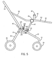
- Fig. 5 is side elevation view of the stroller illustrated in Fig. 2 with the seat in a vertically adjusted position;
- Fig. 6 is a side elevation view of the stroller illustrated in Fig. 2 in a partially folded configuration
- Fig. 7 is a side elevation view of the stroller illustrated in Fig. 6 , with the stroller frame in a folded, or collapsed, storage configuration.
- a stroller and frame construction provides a stroller with both a seat height-adjust feature and a frame folding or collapsing feature.
- the frame structure includes an adjustment assembly that facilitates both folding and unfolding of the stroller frame between an in-use configuration and a storage configuration, and further facilitates height adjustment of the stroller seat in order to bring the infant or child closer to the care giver when desired by the care giver.
- the adjustment assembly includes a four-bar linkage arrangement that is employed as part of the frame structure, and achieves both the seat height adjust and the frame folding functions.
- a stroller 20 is depicted in FIGS. 1-3 and is constructed in accordance with the teachings of the present invention.
- the disclosed stroller components can be fabricated from aluminum, steel, plastic, combinations of materials, or the like and can be tubular or solid, round or non-round in cross-section, and curved or straight as desired.
- the configuration and construction of the stroller frame assembly can vary considerably and yet fall within the scope of the present invention as defined in the claims.
- the stroller 20 generally has a frame assembly 22 that can advantageously be moved between a folded, or collapsed, storage configuration ( Fig. 1 & and an unfolded, or open, in-use configuration ( Fig. 1 ).
- the stroller 20 includes a seat assembly 24 supported by the frame assembly 22 having a plurality of stroller frame assembly components, and at least one wheel supporting the frame assembly on a ground surface. As illustrated, the stroller 20 is supported by a pair of laterally spaced rear wheel assemblies 26 (one shown) and a pair of laterally spaced front wheel assemblies 28. In this example, the front wheel assemblies 28 have two wheels 30 spaced apart side by side.
- a rear frame leg 34 extends upward and forward from each rear wheel assembly 26.
- the upper end of each rear frame leg 34 is pivotally to a primary frame pivot P1 positioned on each stroller side.
- a front frame leg 32 extends upward and rearward from each front wheel assembly 28.
- the front frame legs 32 are integrally connected at their upper, rearward, ends to a laterally extending cross member 45.
- the front frame legs 32 are connected and fixed at a location forward of the cross member 45 to an upper cross member 46 (see Fig. 4 ) that extends laterally between, and connected to, the two primary frame pivots P1.
- the cross member 45 provides a handle for the caregiver to roll the stroller 20 along a ground support surface when the frame assembly 22 is in its folded configuration.
- the front frame legs 32 can be curved upwards between the front wheel assembly 28 and the cross member 46.
- the forward end of each front frame leg 32 can be integrally connected to the corresponding front wheel assembly 28 via a vertical connector bar 33.
- the frame assembly 22 further includes a stroller handle 43 for pushing and maneuvering the stroller 20.
- the handle 43 can assume any configuration known to one having ordinary skill in the art.
- the handle 43 includes a laterally extending handlebar 38 integrally connected at its outer ends to a pair of handle support arms 36.
- the support arms 36 extend down and forward from the handlebar 38, and are connected at their distal ends to the frame pivot P1.
- the handlebar 38 can be curved such that its middle portion is disposed higher and rearward with respect to its laterally outer ends.
- the handlebar 38 can be equipped with any suitable gripping portion to allow the caregiver to comfortably drive the stroller 20.
- the stroller frame assembly 22 can include a basket assembly 35.
- the basket assembly 35 includes a basket frame in the form of a basket support bar 37 connected laterally between the rear wheel assemblies 26.
- the support bar 37 is curved such that its lateral outer ends are disposed below its center portion.
- a basket 39 in the form of a soft goods material is connected to the support bar 37 at its rear end, and to the front frame legs 32 at its forward end.
- the basket 39 defines a storage compartment 41 for retaining miscellaneous items.
- the seat assembly 24 can advantageously be vertically raised or lowered through a plurality of selected height selections.
- the seat assembly 24 includes a seat support member in the form of a U-shaped seat support bar 42 including a laterally extending crossbar 47 that is integrally connected to a pair of uprights 48 extending perpendicularly out from the laterally outer ends of the cross member 47.
- the outer, free ends of the uprights 48 are pivotally connected to a pair of seat pivots P2 (one shown) positioned on each stroller side.
- the uprights 48 extend upward and rearward from the cross member 47.
- the seat assembly 24 further includes a seat frame 50 that is likewise pivotally connected to the seat pivots P2.
- the seat frame 50 has an upper U-shaped frame member 52 supporting the head and upper torso region of the child supported in the seat assembly 24.
- the seat frame 50 further includes a lower U-shaped frame member 54 supporting the lower torso region of the child supported in the seat assembly 24.
- the armrest 56 is connected to both sides of the seat frame 50.
- the armrest 56 includes an upper surface 58 that is sized and shaped to be comfortably engaged by the child seated in the seat assembly 24.
- the armrest 56 is a solid member extending up from the seat frame 50 to serve as a guide that ensures that the legs of the seated child remain inside the boundaries of the seat assembly 24, particularly when the seat assembly 50 is in a horizontal or carry-cot orientation for use with the seated occupant lying down in the seat.
- the seat assembly 24 can further include an arm bar 60 extending laterally across the seat frame 50 and having outer ends that are integrally connected to the outer ends of support arms 62. The inner ends of the support arms 62 are connected to the seat pivot P2 to allow the arm bar 60 to be folded and unfolded between a collapsed storage position and an in-use position.
- a seat 64 in the form of soft goods material is connected to the seat frame 50 and includes a seat back portion, a seat portion, and a lower torso supporting region.
- the seat assembly 24 can further include a tray for the temporary storage of miscellaneous items, such as food for consumption by the seated occupant or toys, a cup holder for the storage of a beverage, and a canopy.
- the tray, cup holder, and canopy can be constructed in the usual manner.
- the upper frame member 52 is connected at its forward distal ends to the seat pivots P2.
- the lower frame member 54 is connected at its rear distal ends to the seat pivots P2. Accordingly, the seat assembly 24 can pivot about the seat pivots P2 to a desired angular seat orientation.
- the seat 64 assumes a substantially horizontal, or carry-cot, orientation as illustrated in Figs. 1 and 2 , and in the opposite extreme angular orientation, the seat 64 assumes a substantially vertical, or standard seating, orientation shown in phantom in Fig. 2 .
- the angular orientation of the seat 64 can also be set between the two extreme angular orientations.
- the stroller frame assembly 22 includes a pair of seat orientation assemblies 70 on each side of the stroller 20 (one shown) connected between the pivot P2 and the seat assembly 24 that permits adjustment of the angular orientation of the seat 64.
- the orientation assembly 70 includes a plurality of radially spaced detents 72 formed in the laterally inboard surface of a pivot plate 74 forming part of the seat pivot P2.
- the seat frame 50 defines a radially extending aperture 76 that is in circumferential alignment with the detents 72 formed in the pivot plate 74.
- the upper frame member 52 is integrally connected to the lower frame member 54.
- a pawl 78 is disposed within the aperture 76 and has an outer surface sized and shaped to nest within the detents 72. As illustrated, both the detents 72 and the pawl 78 are round.
- a radially extending compression spring 80 is seated within the aperture 76 and biases the pawl 78 against a selected one of the detents 72.
- a spring seat 82 is disposed laterally inboard of the seat frame 50 and is supported by a shaft 84 extending from the inboard surface of the pivot plate 74.
- the shaft 84 supports a washer 86 disposed laterally inboard of the seat frame 50, and a compression spring 88 disposed between the spring seat 82 and the washer 86.
- the compression spring 88 exerts a force against the washer 86 which is a friction member biased against the seat frame 50, and exerts a frictional force against the seat frame 50.
- the seat frame 50 is moved between a plurality of angular orientations by rotating the seat frame 50 clockwise or counterclockwise about seat pivot P2, which causes the pawl 78 to move to, and nest within, an adjacent radial detent 72, thereby locking the seat in a desired angular orientation.
- the seat can be locked in progressively increasingly horizontal or vertical orientations between the horizontal carry-cot orientation and the vertical standard orientation.
- the frictional force applied by the washer 86 against the seat frame 50 is overcome in order to angularly adjust the seat. Accordingly, applied the frictional force assists in preventing unintended angular rotation of the seat frame 50.
- the seat assembly 24 is connected to the front and rear frame legs 32 and 34 via a stroller adjustment assembly in the form of a linkage 90 that facilitates folding and unfolding of the stroller frame assembly 22, and further facilitates raising and lowering of the seat frame 64.
- the linkage 90 allows the seat 64 to be raised and lowered independent of folding and unfolding of the stroller frame assembly 22. Accordingly, the seat height can be adjusted as the angular orientation of the seat 64 is adjusted such that the seated occupant is within easy reach of the caregiver.
- the linkage components disclosed herein can be fabricated from a steel, plastic, such as an injection-molded engineered plastic, or other suitable materials alone or in combination. Components of the linkage can optionally employ other types of biasing and/or damping elements, if desired.
- the linkage 90 is configured as a four-bar linkage positioned beneath the seat assembly 24.
- the four-bar linkage 90 is supported by the upper cross member 46 extending laterally between primary frame pivots P1 and a lower cross member 94 extending laterally between rear frame legs 34.
- the lower cross member 94 is spaced below the upper cross member 46.
- the linkage 90 includes a pair of laterally spaced elongated upper links 96. Each upper link 96 defines a rear end 98 and a front end 100, each of which defining a corresponding apertures 102 and 104, respectively, extending laterally therethrough.
- the linkage 90 further includes a pair of laterally spaced elongated lower links 106 that are disposed below the upper links 96.
- Each lower link 106 defines a rear end 108 and a front end 110, each of which defining a corresponding apertures 112 and 114, respectively, extending laterally therethrough.
- the rear ends 98 and 108 of the links 96 and 106 are thus connected to the stroller frame 22.
- the linkage 90 further includes a pair of laterally spaced elongated forward links 116 extending between the front ends 100 and 110 of the upper and lower links 96 and 106, respectively.
- Each forward link 116 defines an upper end 118 and a lower end 120, each of which defining a corresponding aperture 122 and 124, respectively, extending laterally therethrough.
- the links 96, 106, and 116 can assume virtually any desirable shape, and are rectangular in the illustrated embodiment.
- the front end 100 of the upper links 96 and the upper ends 118 of the forward links 116 are connected to the seat assembly 24.
- the upper cross member 46 extends through the rear apertures 102 of the upper links 96 such that the links 96 can rotate about the upper cross member 46.
- the lower cross member 94 extends through the rear apertures 112 of the lower links 106 such that the links 106 can rotate about the lower cross member 94.
- the front apertures 114 of the lower links 106 and the lower apertures 124 of the forward links 116 receive a front cross member 126 such that the forward links 116 are spaced laterally inboard of the lower links 106. The forward links 116 can thus pivot about the front cross member 126 with respect to the lower links 106.
- the upper apertures 122 of the forward links 116 and the front apertures 104 of the upper links 96 receive the cross member 47 of the seat support bar 42 such that the forward links 116 do not rotate with respect to the seat support bar 42 when the stroller is in the in-use configuration.
- the seat support bar 42 thus structurally supports the seat assembly 24 when the pins are in place.
- the upper links 96 are connected so as to rotate about the cross member 47.
- the upper links 96 are thus rotatable about the cross member 47 with respect to the forward links 116.
- the linkage 90 is thus a four-bar linkage (substantially defining a parallelogram) that is defined by the upper link 96, the lower link 106, the forward link 116, and that portion of the rear frame leg 34 extending between the upper cross member 46 and the lower cross member 94.
- the linkage 90 supports the seat assembly 24 and facilitates height adjustment of the seat assembly 24; as will now be described.
- the seat support bar 42 is raised as the upper and lower links 96 and 106 are rotated counterclockwise about the upper and lower cross members 46 and 94 in the direction of Arrow A. It should be appreciated that as the seat support bar 42 is raised and lowered, the seat assembly 24 is raised and lowered accordingly. Likewise, the seat support bar 42 is lowered as the upper and lower links 96 and 106 are rotated clockwise about the upper and lower cross members 46 and 94 in the direction of Arrow B.
- the pivotal connections of the upper link 96, lower link 106, and forward link 116 allow the linkage 90 to accommodate the movement of the seat support bar 42.
- the frame assembly 22 can include a latch member 130 having a lower end that is mounted onto one of the front frame legs 32.
- the latch member 130 is curved upward and rearward from the front frame leg 32 in a direction of the arcuate motion of the corresponding upper link 96 as the link 96 rotates to raise and lower the seat assembly 24.
- a plurality of spaced locating apertures 132 extends through the latch member 130 and is circumferentially aligned with an aperture 134 extending through the upper link 96 (see Fig. 4 ).
- a pin 136 is provided having a shaft sized to extend through one of the apertures 132 of the latch member 130 and further through the aperture 134 extending through the upper link 96.
- the upper link 96 can be raised and lowered such that the aperture 134 is aligned with a selected one of the apertures 132 corresponding to a desired seat height.
- the pin 136 can then be inserted through a select one of the apertures 132 and further through aperture 134 to lock the seat assembly 24 in the desired vertical position.
- Raising and lowering the upper link 96 causes the lower link 106 to rotate along with the upper link 96 about the upper and lower cross members 46 and 94, respectively.
- the linkage 90 causes the seat height to raise and lower without causing the stroller frame 22 to move between its folded and unfolded configuration.
- the pin 136 can be removed and the seat assembly 24 can be raised or lowered to a second desired height among a plurality of vertical locations or heights defined by the alignment of apertures 132 and 134, at which point the pin 136 is again inserted to lock the seat assembly 24 at the second desired height.
- Two vertically adjusted seat heights are illustrated in Figs. 2 and 5 .
- a torsion spring 138 can be mounted onto one of the cross members 46 and 94, and as illustrated in Fig. 4 , is mounted onto the upper cross member 46, and biases one of the upper links 96 in the counterclockwise direction of Arrow C to assist the user when raising the seat assembly 24, and to prevent the seat assembly 24 from collapsing to the lowermost position under gravitational forces when the pin 136 is removed from the aperture 134.
- the linkage 90 further assists in folding the stroller frame assembly 22 to a compact flat storage configuration.
- the linkage 90 operatively connects two frame member components and drives one frame member to its folded configuration in response to movement of another, linked, frame member to its folded configuration.
- the linkage 90 operatively connects rear legs 34 to the seat support bar 42 as the stroller frame assembly 22 is folded and unfolded.
- the frame assembly 22 can be folded by first lowering the seat assembly 24 from its unfolded position to its folded storage position. Specifically, the pin 136 is removed from at least aperture 134 and the selected aperture 132, if desired, and the seat assembly 34 is rotated clockwise about the direction of Arrow D until the cross member 47 of the seat support bar 42 rests against the upper surface of the front frame legs 32. If desired, one or more latch members 140 (See Fig. 1 ) can be mounted to the front frame legs 32 to lock the cross member 47 in its lowermost position.
- the latch member 140 can include an arm that can be extended over the top of the cross member 47, or alternatively can include a plunger at its outer end that becomes depressed as the cross member 47 cams over the latch 140, and springs back out over the cross member 47 to lock the crossbar in its lowermost position.
- the handle 43 is moved from its unfolded position to its folded storage position by rotating the handle 43 clockwise in the direction of Arrow E until the handle support arms 36 extend in a direction substantially parallel with the front frame legs 32, at which point the handle is in the folded position.
- the handle support arms 36 define a lateral distance therebetween that is greater than the lateral distance between the front frame legs 32 such that the front frame legs 32 are disposed between the handle support arms 36 when the handle 43 is folded.
- the handlebar 38 extends across the upper surfaces of the front frame legs 32 when the handle 43 is folded.
- the arm bar 60 is moved from its unfolded position to its folded storage position by rotating the arm bar 60 counterclockwise in the direction of Arrow F (see Fig. 6 ) until it nests inside the stroller frame 50.
- the upper frame member 52 is pivotally connected to the lower frame member 54, then the upper frame member is moved from its unfolded position to its folded position by rotating the upper frame member 52 clockwise about seat pivot P2 in the direction of Arrow G until the upper frame member 52 is folded onto the lower frame member 54.
- the rear frame legs 34 are moved from their unfolded position to their folded storage position by rotating the legs 34 counterclockwise in the direction of Arrow H until the rear frame legs 34 extend substantially parallel with the front frame legs 32.
- the basket support bar 37 likewise travels along with the rear frame legs 34. Because the lateral distance between the rear wheel assemblies 26 is greater than the distance between the front wheel assemblies, the front wheel assemblies 28 are disposed between the rear wheel assemblies 26 when the rear frame legs 34 are folded. Rotation of the rear frame legs 34 displaces the lower cross member 94 in a direction forward with respect to the upper cross member 46.
- the forward motion of the lower cross member 94 causes the lower links 106 to correspondingly drive the lower ends 120 of the forward links 116 in a forward direction, thus causing the upper ends 118 of the forward links 116 to drive the uprights 48 of the seat support bar 42 to an orientation substantially parallel with the front frame legs 32.
- the stroller frame 22 can be unfolded to its in-use configuration by rotating the rear frame legs 34 clockwise to their in-use configuration, which drives the linkage 90 to urge the seat support bar 46 to its in-use configuration.
- the linkage 90 drives one frame member component to be unfolded automatically in response to another frame member component being moved to its unfolded configuration.
- the upper frame member 52 is pivotally connected to the lower frame member 54, the upper frame member 52 is rotated counterclockwise about pivot P2 with respect to the lower frame member 54 to its in-use configuration.
- the stroller handle 43 is rotated counterclockwise to its in-use configuration.
- the present invention thus provides a stroller 20 that advantageously incorporate a four-bar linkage 90 that performs two discrete functions: to assist with raising or elevating an infant/child seat or carry-cot; and to assist with folding or collapsing the frame structure of the stroller assembly.
- the angular orientation of the seat 64 can be adjusted to assume in a carry-cot orientation or a standard seating orientation (and angular positions therebetween), and the height of the seat 64 can be adjusted to allow the occupant to be placed in a raised position to minimize the bending required of the care-giver.
- the folding feature can be employed with a gas-assist and/or damping cylinder and/or one or more biasing elements such as torsion springs in varying degrees to improve the overall function and ease of movement of the components.
Abstract
Description
- This patent is related to and claims priority benefit of
U.S. Provisional Patent Application No. 60/799,177, which was filed on May 10, 2006 - The present disclosure is generally directed to strollers, and more particularly to a stroller with a frame structure that permits seat height adjustment and can be moved between an in-use configuration and a collapsed or folded configuration.
- Well-designed strollers should be sturdy and balanced, and should provide the child passenger with safe and comfortable transport. Throughout the development of strollers, an effort has been made to include features that render the stroller versatile and convenient. Efforts have been made to provide these features while achieving a simple design, yet maintaining the stroller rugged and reliable.
- A conventional stroller has a plurality of wheels supporting a stroller frame that supports one or more stroller seats. Some conventional stroller frames can be moved between an in-use position and a collapsed or folded configuration for easy, space-minimizing storage. Some conventional stroller seats can be articulated to a horizontal position so that an infant can lie in a prone position while riding in the stroller. Unfortunately, the seats have a fixed height, and define a distance to the caregiver that requires the caregiver to bend substantially to reach the infant, if needed. A stroller according to the preamble of claim 1 is shown by
FR-A1-2 458 443 - What is therefore needed is a stroller having a seat supported by the stroller frame that is height-adjustable and capable of articulating between a vertical and a horizontal orientation. It would further be desirable that such a stroller be configured to move between a folded, or collapsed, storage configuration and an unfolded, or open, in-use configuration.
- In accordance with the present invention as defined in claim 1, a stroller is provided that is foldable between an open configuration and a folded configuration. The stroller includes a stroller frame having a plurality of stroller frame components. The stroller frame is movably supported by at least one wheel. A seat assembly is supported by the stroller frame. The seat assembly includes a seat that can be moved between a first height and a second height different than the first height. A linkage has a first end connected to the stroller frame and a second end connected to the seat assembly. The linkage joins a first and second stroller frame component such that movement of the first stroller frame component between its folded and an unfolded configuration causes the second stroller frame component to correspondingly move between its folded and unfolded configuration.
- It should be appreciated that the foregoing and other aspects of the invention will appear from the following description. In the description, reference is made to the accompanying drawings which form a part thereof, and in which there is shown by way of illustration, and not limitation, preferred embodiments of the invention. Such embodiments do not necessarily represent the full scope of the invention, and reference must therefore be made to the claims herein for interpreting the full scope of the invention.
- Objects, features, and advantages of the present invention will become apparent upon reading the following description in conjunction with the drawing figures, in which:
-
Fig. 1 is a perspective view of a stroller including a stroller frame assembly having an adjustment assembly constructed in accordance with certain aspects of the present invention; -
Fig. 2 is a side elevation view of the stroller illustrated inFig. 1 with the soft goods removed to reveal the stroller frame assembly; (seat rotatable in phantom position) -
Fig. 3 is a sectional side elevation view taken along line 3-3 ofFig. 2 ; -
Fig. 4 is a perspective view of the stroller illustrated inFig. 1 with portions cut away illustrating the adjustment assembly and related stroller components; -
Fig. 5 is side elevation view of the stroller illustrated inFig. 2 with the seat in a vertically adjusted position; -
Fig. 6 is a side elevation view of the stroller illustrated inFig. 2 in a partially folded configuration; and -
Fig. 7 is a side elevation view of the stroller illustrated inFig. 6 , with the stroller frame in a folded, or collapsed, storage configuration. - A stroller and frame construction is disclosed and provides a stroller with both a seat height-adjust feature and a frame folding or collapsing feature. In one example, the frame structure includes an adjustment assembly that facilitates both folding and unfolding of the stroller frame between an in-use configuration and a storage configuration, and further facilitates height adjustment of the stroller seat in order to bring the infant or child closer to the care giver when desired by the care giver. In one aspect, the adjustment assembly includes a four-bar linkage arrangement that is employed as part of the frame structure, and achieves both the seat height adjust and the frame folding functions.
- Turning now to the drawings, a
stroller 20 is depicted inFIGS. 1-3 and is constructed in accordance with the teachings of the present invention. The disclosed stroller components can be fabricated from aluminum, steel, plastic, combinations of materials, or the like and can be tubular or solid, round or non-round in cross-section, and curved or straight as desired. As will be evident to those having ordinary skill in the art, the configuration and construction of the stroller frame assembly can vary considerably and yet fall within the
scope of the present invention as defined in the claims. In the disclosed example, thestroller 20 generally has aframe assembly 22 that can advantageously be moved between a folded, or collapsed, storage configuration (Fig. 1 & and an unfolded, or open, in-use configuration (Fig. 1 ). - The
stroller 20 includes aseat assembly 24 supported by theframe assembly 22 having a plurality of stroller frame assembly components, and at least one wheel supporting the frame assembly on a ground surface. As illustrated, thestroller 20 is supported by a pair of laterally spaced rear wheel assemblies 26 (one shown) and a pair of laterally spacedfront wheel assemblies 28. In this example, the front wheel assemblies 28 have twowheels 30 spaced apart side by side. - A
rear frame leg 34 extends upward and forward from eachrear wheel assembly 26. In the illustrated embodiment, the upper end of eachrear frame leg 34 is pivotally to a primary frame pivot P1 positioned on each stroller side. Afront frame leg 32 extends upward and rearward from eachfront wheel assembly 28. Thefront frame legs 32 are integrally connected at their upper, rearward, ends to a laterally extendingcross member 45. Thefront frame legs 32 are connected and fixed at a location forward of thecross member 45 to an upper cross member 46 (seeFig. 4 ) that extends laterally between, and connected to, the two primary frame pivots P1. Thecross member 45 provides a handle for the caregiver to roll thestroller 20 along a ground support surface when theframe assembly 22 is in its folded configuration. Thefront frame legs 32 can be curved upwards between thefront wheel assembly 28 and thecross member 46. The forward end of eachfront frame leg 32 can be integrally connected to the correspondingfront wheel assembly 28 via avertical connector bar 33. - The
frame assembly 22 further includes astroller handle 43 for pushing and maneuvering thestroller 20. Thehandle 43 can assume any configuration known to one having ordinary skill in the art. In the illustrated embodiment, thehandle 43 includes a laterally extendinghandlebar 38 integrally connected at its outer ends to a pair ofhandle support arms 36. When thestroller 20 is in the in-use configuration, thesupport arms 36 extend down and forward from thehandlebar 38, and are connected at their distal ends to the frame pivot P1. Thehandlebar 38 can be curved such that its middle portion is disposed higher and rearward with respect to its laterally outer ends. Thehandlebar 38 can be equipped with any suitable gripping portion to allow the caregiver to comfortably drive thestroller 20. - The
stroller frame assembly 22 can include abasket assembly 35. Thebasket assembly 35 includes a basket frame in the form of abasket support bar 37 connected laterally between therear wheel assemblies 26. Thesupport bar 37 is curved such that its lateral outer ends are disposed below its center portion. Abasket 39 in the form of a soft goods material is connected to thesupport bar 37 at its rear end, and to thefront frame legs 32 at its forward end. Thebasket 39 defines astorage compartment 41 for retaining miscellaneous items. - The
seat assembly 24 can advantageously be vertically raised or lowered through a plurality of selected height selections. Theseat assembly 24 includes a seat support member in the form of a U-shapedseat support bar 42 including a laterally extendingcrossbar 47 that is integrally connected to a pair ofuprights 48 extending perpendicularly out from the laterally outer ends of thecross member 47. The outer, free ends of theuprights 48 are pivotally connected to a pair of seat pivots P2 (one shown) positioned on each stroller side. When thestroller frame assembly 22 is in the in-use configuration, theuprights 48 extend upward and rearward from thecross member 47. - The
seat assembly 24 further includes aseat frame 50 that is likewise pivotally connected to the seat pivots P2. Theseat frame 50 has an upperU-shaped frame member 52 supporting the head and upper torso region of the child supported in theseat assembly 24. Theseat frame 50 further includes a lowerU-shaped frame member 54 supporting the lower torso region of the child supported in theseat assembly 24. - An armrest 56 is connected to both sides of the
seat frame 50. Thearmrest 56 includes anupper surface 58 that is sized and shaped to be comfortably engaged by the child seated in theseat assembly 24. Furthermore, thearmrest 56 is a solid member extending up from theseat frame 50 to serve as a guide that ensures that the legs of the seated child remain inside the boundaries of theseat assembly 24, particularly when theseat assembly 50 is in a horizontal or carry-cot orientation for use with the seated occupant lying down in the seat. Theseat assembly 24 can further include anarm bar 60 extending laterally across theseat frame 50 and having outer ends that are integrally connected to the outer ends ofsupport arms 62. The inner ends of thesupport arms 62 are connected to the seat pivot P2 to allow thearm bar 60 to be folded and unfolded between a collapsed storage position and an in-use position. - A
seat 64 in the form of soft goods material (e.g., a fabric or mesh) is connected to theseat frame 50 and includes a seat back portion, a seat portion, and a lower torso supporting region. Though not illustrated, theseat assembly 24 can further include a tray for the temporary storage of miscellaneous items, such as food for consumption by the seated occupant or toys, a cup holder for the storage of a beverage, and a canopy. The tray, cup holder, and canopy can be constructed in the usual manner. - The
upper frame member 52 is connected at its forward distal ends to the seat pivots P2. Thelower frame member 54 is connected at its rear distal ends to the seat pivots P2. Accordingly, theseat assembly 24 can pivot about the seat pivots P2 to a desired angular seat orientation. At one extreme angular orientation, theseat 64 assumes a substantially horizontal, or carry-cot, orientation as illustrated inFigs. 1 and2 , and in the opposite extreme angular orientation, theseat 64 assumes a substantially vertical, or standard seating, orientation shown in phantom inFig. 2 . The angular orientation of theseat 64 can also be set between the two extreme angular orientations. - Specifically, referring now also to
Fig. 3 , thestroller frame assembly 22 includes a pair ofseat orientation assemblies 70 on each side of the stroller 20 (one shown) connected between the pivot P2 and theseat assembly 24 that permits adjustment of the angular orientation of theseat 64. Theorientation assembly 70 includes a plurality of radially spaceddetents 72 formed in the laterally inboard surface of apivot plate 74 forming part of the seat pivot P2. Theseat frame 50 defines aradially extending aperture 76 that is in circumferential alignment with thedetents 72 formed in thepivot plate 74. As illustrated, theupper frame member 52 is integrally connected to thelower frame member 54. Apawl 78 is disposed within theaperture 76 and has an outer surface sized and shaped to nest within thedetents 72. As illustrated, both thedetents 72 and thepawl 78 are round. A radially extendingcompression spring 80 is seated within theaperture 76 and biases thepawl 78 against a selected one of thedetents 72. A spring seat 82 is disposed laterally inboard of theseat frame 50 and is supported by ashaft 84 extending from the inboard surface of thepivot plate 74. Theshaft 84 supports a washer 86 disposed laterally inboard of theseat frame 50, and acompression spring 88 disposed between the spring seat 82 and the washer 86. Thecompression spring 88 exerts a force against the washer 86 which is a friction member biased against theseat frame 50, and exerts a frictional force against theseat frame 50. - During operation, the
seat frame 50 is moved between a plurality of angular orientations by rotating theseat frame 50 clockwise or counterclockwise about seat pivot P2, which causes thepawl 78 to move to, and nest within, anadjacent radial detent 72, thereby locking the seat in a desired angular orientation. Depending on the direction of seat frame rotation, the seat can be locked in progressively increasingly horizontal or vertical orientations between the horizontal carry-cot orientation and the vertical standard orientation. The frictional force applied by the washer 86 against theseat frame 50 is overcome in order to angularly adjust the seat. Accordingly, applied the frictional force assists in preventing unintended angular rotation of theseat frame 50. - The
seat assembly 24 is connected to the front andrear frame legs linkage 90 that facilitates folding and unfolding of thestroller frame assembly 22, and further facilitates raising and lowering of theseat frame 64. Advantageously, thelinkage 90 allows theseat 64 to be raised and lowered independent of folding and unfolding of thestroller frame assembly 22. Accordingly, the seat height can be adjusted as the angular orientation of theseat 64 is adjusted such that the seated occupant is within easy reach of the caregiver. The linkage components disclosed herein can be fabricated from a steel, plastic, such as an injection-molded engineered plastic, or other suitable materials alone or in combination. Components of the linkage can optionally employ other types of biasing and/or damping elements, if desired. Other alternate linkage arrangements, other than a four-bar type arrangement can also be employed to achieve the seat height adjust feature, the fold assist feature, or a combination of these features. As described above, one skilled in the art will appreciate that the various stroller components can very in size, shape, and configuration without departing from the scope of the present invention. - Referring now to
Fig. 4 , thelinkage 90 is configured as a four-bar linkage positioned beneath theseat assembly 24. The four-bar linkage 90 is supported by theupper cross member 46 extending laterally between primary frame pivots P1 and alower cross member 94 extending laterally betweenrear frame legs 34. Thelower cross member 94 is spaced below theupper cross member 46. - The
linkage 90 includes a pair of laterally spaced elongatedupper links 96. Eachupper link 96 defines arear end 98 and afront end 100, each of which defining acorresponding apertures linkage 90 further includes a pair of laterally spaced elongatedlower links 106 that are disposed below theupper links 96. Eachlower link 106 defines arear end 108 and afront end 110, each of which defining acorresponding apertures links stroller frame 22. Thelinkage 90 further includes a pair of laterally spaced elongatedforward links 116 extending between thefront ends lower links forward link 116 defines anupper end 118 and alower end 120, each of which defining acorresponding aperture links front end 100 of theupper links 96 and the upper ends 118 of theforward links 116 are connected to theseat assembly 24. - The
upper cross member 46 extends through therear apertures 102 of theupper links 96 such that thelinks 96 can rotate about theupper cross member 46. Likewise, thelower cross member 94 extends through therear apertures 112 of thelower links 106 such that thelinks 106 can rotate about thelower cross member 94. Thefront apertures 114 of thelower links 106 and thelower apertures 124 of theforward links 116 receive afront cross member 126 such that theforward links 116 are spaced laterally inboard of thelower links 106. Theforward links 116 can thus pivot about thefront cross member 126 with respect to thelower links 106. Theupper apertures 122 of theforward links 116 and thefront apertures 104 of theupper links 96 receive thecross member 47 of theseat support bar 42 such that theforward links 116 do not rotate with respect to theseat support bar 42 when the stroller is in the in-use configuration. Theseat support bar 42 thus structurally supports theseat assembly 24 when the pins are in place. Theupper links 96 are connected so as to rotate about thecross member 47. Theupper links 96 are thus rotatable about thecross member 47 with respect to theforward links 116. - The
linkage 90 is thus a four-bar linkage (substantially defining a parallelogram) that is defined by theupper link 96, thelower link 106, theforward link 116, and that portion of therear frame leg 34 extending between theupper cross member 46 and thelower cross member 94. Thelinkage 90 supports theseat assembly 24 and facilitates height adjustment of theseat assembly 24; as will now be described. - Specifically, referring to
Figs. 2 and4 and5 , theseat support bar 42 is raised as the upper andlower links lower cross members seat support bar 42 is raised and lowered, theseat assembly 24 is raised and lowered accordingly. Likewise, theseat support bar 42 is lowered as the upper andlower links lower cross members upper link 96,lower link 106, andforward link 116 allow thelinkage 90 to accommodate the movement of theseat support bar 42. - As illustrated in
Fig. 2 , theframe assembly 22 can include alatch member 130 having a lower end that is mounted onto one of thefront frame legs 32. Thelatch member 130 is curved upward and rearward from thefront frame leg 32 in a direction of the arcuate motion of the correspondingupper link 96 as thelink 96 rotates to raise and lower theseat assembly 24. A plurality of spaced locatingapertures 132 extends through thelatch member 130 and is circumferentially aligned with anaperture 134 extending through the upper link 96 (seeFig. 4 ). Apin 136 is provided having a shaft sized to extend through one of theapertures 132 of thelatch member 130 and further through theaperture 134 extending through theupper link 96. Theupper link 96 can be raised and lowered such that theaperture 134 is aligned with a selected one of theapertures 132 corresponding to a desired seat height. Thepin 136 can then be inserted through a select one of theapertures 132 and further throughaperture 134 to lock theseat assembly 24 in the desired vertical position. - Raising and lowering the
upper link 96 causes thelower link 106 to rotate along with theupper link 96 about the upper andlower cross members linkage 90 causes the seat height to raise and lower without causing thestroller frame 22 to move between its folded and unfolded configuration. - The
pin 136 can be removed and theseat assembly 24 can be raised or lowered to a second desired height among a plurality of vertical locations or heights defined by the alignment ofapertures pin 136 is again inserted to lock theseat assembly 24 at the second desired height. Two vertically adjusted seat heights are illustrated inFigs. 2 and5 . - Referring again to
Fig. 4 , atorsion spring 138 can be mounted onto one of thecross members Fig. 4 , is mounted onto theupper cross member 46, and biases one of theupper links 96 in the counterclockwise direction of Arrow C to assist the user when raising theseat assembly 24, and to prevent theseat assembly 24 from collapsing to the lowermost position under gravitational forces when thepin 136 is removed from theaperture 134. - Advantageously, the
linkage 90 further assists in folding thestroller frame assembly 22 to a compact flat storage configuration. In particular, thelinkage 90 operatively connects two frame member components and drives one frame member to its folded configuration in response to movement of another, linked, frame member to its folded configuration. In the illustrated embodiment, thelinkage 90 operatively connectsrear legs 34 to theseat support bar 42 as thestroller frame assembly 22 is folded and unfolded. - Referring now to
Figs. 6-7 , theframe assembly 22 can be folded by first lowering theseat assembly 24 from its unfolded position to its folded storage position. Specifically, thepin 136 is removed from atleast aperture 134 and the selectedaperture 132, if desired, and theseat assembly 34 is rotated clockwise about the direction of Arrow D until thecross member 47 of theseat support bar 42 rests against the upper surface of thefront frame legs 32. If desired, one or more latch members 140 (SeeFig. 1 ) can be mounted to thefront frame legs 32 to lock thecross member 47 in its lowermost position. Thelatch member 140 can include an arm that can be extended over the top of thecross member 47, or alternatively can include a plunger at its outer end that becomes depressed as thecross member 47 cams over thelatch 140, and springs back out over thecross member 47 to lock the crossbar in its lowermost position. - Next, the
handle 43 is moved from its unfolded position to its folded storage position by rotating thehandle 43 clockwise in the direction of Arrow E until thehandle support arms 36 extend in a direction substantially parallel with thefront frame legs 32, at which point the handle is in the folded position. Thehandle support arms 36 define a lateral distance therebetween that is greater than the lateral distance between thefront frame legs 32 such that thefront frame legs 32 are disposed between thehandle support arms 36 when thehandle 43 is folded. Thehandlebar 38 extends across the upper surfaces of thefront frame legs 32 when thehandle 43 is folded. - Next, the
arm bar 60 is moved from its unfolded position to its folded storage position by rotating thearm bar 60 counterclockwise in the direction of Arrow F (seeFig. 6 ) until it nests inside thestroller frame 50. Next, if theupper frame member 52 is pivotally connected to thelower frame member 54, then the upper frame member is moved from its unfolded position to its folded position by rotating theupper frame member 52 clockwise about seat pivot P2 in the direction of Arrow G until theupper frame member 52 is folded onto thelower frame member 54. - Finally, the
rear frame legs 34 are moved from their unfolded position to their folded storage position by rotating thelegs 34 counterclockwise in the direction of Arrow H until therear frame legs 34 extend substantially parallel with thefront frame legs 32. Thebasket support bar 37 likewise travels along with therear frame legs 34. Because the lateral distance between therear wheel assemblies 26 is greater than the distance between the front wheel assemblies, thefront wheel assemblies 28 are disposed between therear wheel assemblies 26 when therear frame legs 34 are folded. Rotation of therear frame legs 34 displaces thelower cross member 94 in a direction forward with respect to theupper cross member 46. The forward motion of thelower cross member 94 causes thelower links 106 to correspondingly drive the lower ends 120 of theforward links 116 in a forward direction, thus causing the upper ends 118 of theforward links 116 to drive theuprights 48 of theseat support bar 42 to an orientation substantially parallel with thefront frame legs 32. - The
stroller frame 22 can be unfolded to its in-use configuration by rotating therear frame legs 34 clockwise to their in-use configuration, which drives thelinkage 90 to urge theseat support bar 46 to its in-use configuration. Advantageously, thelinkage 90 drives one frame member component to be unfolded automatically in response to another frame member component being moved to its unfolded configuration. Next, if theupper frame member 52 is pivotally connected to thelower frame member 54, theupper frame member 52 is rotated counterclockwise about pivot P2 with respect to thelower frame member 54 to its in-use configuration. Finally, the stroller handle 43 is rotated counterclockwise to its in-use configuration. - The present invention thus provides a
stroller 20 that advantageously incorporate a four-bar linkage 90 that performs two discrete functions: to assist with raising or elevating an infant/child seat or carry-cot; and to assist with folding or collapsing the frame structure of the stroller assembly. The angular orientation of theseat 64 can be adjusted to assume in a carry-cot orientation or a standard seating orientation (and angular positions therebetween), and the height of theseat 64 can be adjusted to allow the occupant to be placed in a raised position to minimize the bending required of the care-giver. The folding feature can be employed with a gas-assist and/or damping cylinder and/or one or more biasing elements such as torsion springs in varying degrees to improve the overall function and ease of movement of the components.
Claims (14)
- A stroller (20), movable between an unfolded configuration and a folded configuration, the stroller (20) comprising:a stroller frame (22) including a plurality of stroller frame components, wherein the stroller frame (22) is movably supported by at least one wheel (26, 28);a seat assembly (24) supported by the stroller frame (22), the seat assembly (24) including a seat (64) that can be moved between a first height and a second height different than the first height;a linkage (90) having a first end connected to the stroller frame (22), and having a second end connected to the seat assembly (24), wherein the linkage (90) operatively joins a first and second stroller frame component such that movement of the first stroller frame component between a folded and an unfolded position causes the second stroller frame component to correspondingly move between a folded and unfolded position,characterized in that the linkage (90) is disposed entirely under the seat (64), the linkage (90) supports the seat (64) such that the height of the seat (64) is adjustable without causing the stroller frame (22) to be moved toward the folded or unfolded configuration, and the seat (64) is connected to the frame assembly only through the linkage (90).
- The stroller as recited in claim 1, wherein the first stroller frame component is a rear leg supporting a rear wheel assembly, and a seat support member supporting the seat assembly.
- The stroller as recited in claim 1, further comprising a latch configured to lock the seat assembly at a selected height.
- The stroller as recited in claim 1, wherein the seat assembly comprises a pivot and a seat frame pivotally connected to the pivot such that the angular orientation of the seat frame is adjustable.
- The stroller as recited in claim 1, wherein the stroller frame comprises an outwardly projecting handle pivotally connected for movement between a folded position and an unfolded position.
- The stroller as recited in claim 1, wherein the linkage comprises a four-bar linkage.
- The stroller as recited in claim 1, wherein the linkage comprises an upper link and a lower link, each having a front and rear end, the front ends of the upper and lower links connected to a forward link, and the rear ends of the upper and lower link connected to an upper and lower crossbar, respectively, and optionally the stroller frame comprises a rear leg supported by a rear wheel assembly, wherein the rear leg is connected to the upper and lower crossbars, and the forward link may be connected to the seat assembly by a seat support tube, and movement of the rear leg from an -unfolded position to a folded position may drive the linkage to correspondingly move the seat support tube from the unfolded position to the folded position.
- The stroller as recited in claim 1, wherein the seat is movable between the first and second seat heights without causing the stroller frame to move between the unfolded configuration and the folded configuration.
- The stroller as recited in claim 1, wherein the linkage is movable from a first position that defines the first height of the seat to a second position that defines the second height of the seat.
- The stroller as recited in claim 9, wherein movement of the linkage between the first position and the second position does not cause the stroller frame to move between the unfolded configuration and the folded configuration.
- The stroller as recited in claim 1, wherein the linkage further comprises a spring member biasing the linkage in a direction that causes the seat height to raise.
- The stroller as recited in claim 1, wherein the seat is able to move in a plurality of intervals between the first height and the second height.
- The stroller as recited in claim 1, wherein the stroller frame includes at least one front leg supported by a front wheel assembly, a rear leg supported by a rear wheel assembly, the rear leg pivotally connected with respect to the front leg, wherein the seat assembly includes a seat support member pivotally connected with respect to the front leg; and, and wherein the linkage is connected to the seat support member and the rear leg such that movement of the rear leg from an unfolded position to a folded position causes the linkage to bias the seat support member from an unfolded position to a folded position.
- The stroller as recited in claim 1, wherein the seat assembly further comprises a seat frame that is pivotally mounted to the linkage so as to be angularly adjustable between a vertical and a horizontal orientation.
Applications Claiming Priority (2)
| Application Number | Priority Date | Filing Date | Title |
|---|---|---|---|
| US79917706P | 2006-05-10 | 2006-05-10 | |
| PCT/US2007/068696 WO2007134185A2 (en) | 2006-05-10 | 2007-05-10 | Foldable and height-adjustable stroller |
Publications (2)
| Publication Number | Publication Date |
|---|---|
| EP2015976A2 EP2015976A2 (en) | 2009-01-21 |
| EP2015976B1 true EP2015976B1 (en) | 2009-12-02 |
Family
ID=38582073
Family Applications (1)
| Application Number | Title | Priority Date | Filing Date |
|---|---|---|---|
| EP07783604A Expired - Fee Related EP2015976B1 (en) | 2006-05-10 | 2007-05-10 | Foldable and height-adjustable stroller |
Country Status (5)
| Country | Link |
|---|---|
| US (1) | US7694996B2 (en) |
| EP (1) | EP2015976B1 (en) |
| CN (1) | CN101443222B (en) |
| DE (1) | DE602007003585D1 (en) |
| WO (1) | WO2007134185A2 (en) |
Families Citing this family (46)
| Publication number | Priority date | Publication date | Assignee | Title |
|---|---|---|---|---|
| US7753398B2 (en) * | 2006-08-25 | 2010-07-13 | Link Treasure Limited | Baby stroller frame with seat direction changing mechanism |
| DE102006055052A1 (en) * | 2006-11-22 | 2008-05-29 | Eos Gmbh Electro Optical Systems | Apparatus for layering a three-dimensional object |
| EP2344371B1 (en) | 2007-04-13 | 2013-10-30 | Phil And Teds Most Excellent Buggy Company Limited | Collapsible two seat perambulator |
| US8251382B2 (en) * | 2007-06-06 | 2012-08-28 | Wonderland Nurserygoods Co., Ltd. | Stroller and seat assembly mechanism for a stroller |
| GB0724513D0 (en) * | 2007-12-17 | 2008-01-23 | Mamas & Papas Holdings Ltd | improvements in pushchairs |
| US8282119B1 (en) * | 2007-12-26 | 2012-10-09 | Kristina Caksa | Two-level travel stroller for children |
| US20090295128A1 (en) * | 2008-03-04 | 2009-12-03 | Nagelski Keith C | Stroller, child safety seat and child safety system |
| US8764048B1 (en) * | 2009-01-08 | 2014-07-01 | Graco Children's Products Inc. | Foldable, removable, reversible stroller seat |
| US8534698B2 (en) * | 2009-02-27 | 2013-09-17 | Graco Children's Products Inc. | Fold latch for a foldable stroller |
| CN101934810B (en) * | 2009-06-30 | 2013-01-23 | 明门实业股份有限公司 | Baby carriage and bracket adjusting device |
| CN102030026B (en) * | 2009-09-24 | 2012-10-31 | 明门香港股份有限公司 | Baby supporting device with bidirectional use mode and operating method thereof |
| CN102039920B (en) * | 2009-10-14 | 2012-11-28 | 明门香港股份有限公司 | Baby carriage capable of being integrated with car safety seat |
| CN103153750B (en) * | 2010-03-23 | 2016-12-07 | 雅沙娜美国股份有限公司 | There is the stroller of moved seat adnexa |
| ES1072210Y (en) * | 2010-04-07 | 2010-09-06 | Jane Sa | FOLDING CHASSIS FOR CARS-CHILD CHAIR |
| CN102233893B (en) * | 2010-04-29 | 2013-05-01 | 明门香港股份有限公司 | Bidirectional baby carrying device and operation method thereof |
| CN102241255B (en) * | 2010-05-13 | 2013-06-05 | 荷兰商伍轮实业股份有限公司 | Latch device for coupling a carrier to a stroller frame and a stroller frame capable of assembling the carrier |
| CN202156449U (en) * | 2010-05-27 | 2012-03-07 | 明门香港股份有限公司 | Ceiling device and baby handcart with the same |
| US8523218B2 (en) * | 2010-08-09 | 2013-09-03 | Europe Brands S.A.R.L. | Stroller with articulating structure |
| DE102010037506A1 (en) * | 2010-09-13 | 2012-03-15 | Greentom Taiwan Manufacturing Ltd. | buggy |
| GB201015390D0 (en) * | 2010-09-15 | 2010-10-27 | Icandy World Ltd | A vehicle frame assembly |
| CN102464013B (en) * | 2010-11-01 | 2014-04-23 | 明门(中国)幼童用品有限公司 | Frame for foldable baby carriage |
| ES2396886B1 (en) * | 2011-01-03 | 2014-01-20 | Jane, S.A. | Chassis for strollers with two seats. |
| US8888124B2 (en) | 2011-01-31 | 2014-11-18 | Kolcraft Enterprises, Inc. | Child car seat carriers |
| NL2007332C2 (en) * | 2011-09-02 | 2013-03-05 | Maxi Miliaan Bv | Collapsible pushchair. |
| DE102011116098B4 (en) * | 2011-09-14 | 2013-11-14 | Otto Bock Mobility Solutions Gmbh | Strollers, especially prams |
| EP2572957A3 (en) * | 2011-09-26 | 2017-04-05 | Graco Children's Products, Inc. | Foldable stroller |
| US20130113185A1 (en) * | 2011-11-07 | 2013-05-09 | Dynamic Brands, Llc | Baby stroller |
| NL2008330C2 (en) * | 2012-02-22 | 2013-08-26 | Mutsy Bv | DEVICE AND COMPOSITION FOR TRANSPORTING A CHILD, SUCH AS A CHILDREN'S VEHICLE AND / OR BUGGY. |
| CN103359141B (en) * | 2012-03-28 | 2016-06-01 | 明门香港股份有限公司 | Children trolley and stroller frame thereof |
| US9216755B2 (en) * | 2012-03-30 | 2015-12-22 | Kolcraft Enterprises, Inc. | Foldable strollers |
| US9421992B2 (en) * | 2012-06-13 | 2016-08-23 | Jeff Mills | Infant stroller and swing combination |
| US9399477B2 (en) | 2012-12-27 | 2016-07-26 | Kolcraft Enterprises, Inc. | Strollers with removable child supports and related methods |
| CN105398481A (en) * | 2014-09-15 | 2016-03-16 | 程宝贤 | Folding structure of baby stroller |
| CN104494679B (en) * | 2014-12-15 | 2017-03-01 | 集健重工科技(深圳)有限公司 | Load all moves on to the novel high mother and sons' perambulator on wheel |
| NL2015318B1 (en) * | 2015-08-19 | 2017-03-07 | Maxi Miliaan Bv | Stroller. |
| CN107792153B (en) * | 2016-09-06 | 2020-05-12 | 明门香港股份有限公司 | Folding structure for bicycle frame |
| CN107672663A (en) * | 2017-08-16 | 2018-02-09 | 好孩子儿童用品有限公司 | Children trolley |
| US10829141B2 (en) * | 2018-07-03 | 2020-11-10 | Zhongshan Aifubao Daily Products Co., Ltd. | Trailer for stroller |
| CN108945074B (en) * | 2018-07-03 | 2023-08-25 | 中山市爱福宝日用制品有限公司 | Trailer for handcart |
| CN109501846A (en) * | 2019-01-10 | 2019-03-22 | 邬蓝飞 | A kind of retrieving structure slipping baby's trolley |
| CN109955885A (en) * | 2019-03-14 | 2019-07-02 | 柯全德 | A kind of perambulator of folding convenient |
| NL2023257B1 (en) * | 2019-06-04 | 2020-12-11 | Milk Holding B V | A foldable cot and a buggy |
| WO2022006630A1 (en) * | 2020-07-09 | 2022-01-13 | Morrell Samantha Lian | Stroller |
| EP4263323A1 (en) * | 2020-12-21 | 2023-10-25 | Wonderland Switzerland AG | Multi-fold child carriage |
| RU2764334C1 (en) * | 2021-09-23 | 2022-01-17 | Общество с ограниченной ответственностью "СОЦ-Информ" | Foldable reversible baby stroller |
| US11932300B1 (en) * | 2022-09-01 | 2024-03-19 | Krzysztof Michal Jablonski | Rolling folding frame with simultaneously deployable handle and wheelbase |
Family Cites Families (27)
| Publication number | Priority date | Publication date | Assignee | Title |
|---|---|---|---|---|
| DE2648102A1 (en) | 1976-10-23 | 1978-04-27 | Bbc Brown Boveri & Cie | Power circuit with optimum power near overload region - uses variable delay feedback circuit and overload sensor |
| JPS5583663A (en) * | 1978-12-15 | 1980-06-24 | Kasai Kk | Collapsible baby carriage |
| FR2458443A1 (en) * | 1979-06-05 | 1981-01-02 | Baby Relax | Child's push chair body support - can be adjusted for inclination relative to frame by pivoted side and cross support pieces |
| US5301970A (en) | 1990-07-03 | 1994-04-12 | Haskins John T | Collapsible wheelchair frame construction |
| GB9114794D0 (en) | 1991-07-09 | 1991-08-28 | Britax Teutonia Kinderwagen | Pushchair |
| US5601302A (en) | 1991-11-07 | 1997-02-11 | Board Of Supervisors Of Louisiana State University And Agricultural And Mechanical College Office Of Technology Transfer | Full access wheelchair |
| AU5887494A (en) | 1993-01-20 | 1994-08-15 | Mgb | Foldable assembly for the support or transportation of a person |
| GB9501538D0 (en) * | 1995-01-26 | 1995-03-15 | Kallmeier Paul M | Movement of pushchair seat unit |
| WO1998026971A1 (en) | 1996-12-19 | 1998-06-25 | Form Design Corporation | Suspension for stroller |
| US6099022A (en) | 1998-02-09 | 2000-08-08 | Pring; Dara | Convertible multi-function stroller |
| FR2775241B1 (en) | 1998-02-26 | 2000-04-21 | Team Tex | CHILD STROLLER IN AGE |
| NL1009753C2 (en) * | 1998-07-28 | 2000-02-01 | Royalty Bugaboo S A R L | Buggy. |
| US6193263B1 (en) | 1999-07-19 | 2001-02-27 | Wan-Hsin Lin | Seat positioning frame of a stroller |
| US6398233B1 (en) | 1999-08-16 | 2002-06-04 | Link Treasure Limited | Foldable stroller with separable infant carrier |
| US6715783B1 (en) | 1999-10-29 | 2004-04-06 | Sunrise Medical Hhg Inc. | Stroller and stroller base with height adjustment capability |
| US6209892B1 (en) | 1999-12-14 | 2001-04-03 | William Chester Schaaf | Baby stroller apparatus for use in combination with a standard child's car seat |
| US6540250B1 (en) | 2000-05-12 | 2003-04-01 | Clifford D. Peterson | Height adjustable wheelchair |
| US6976699B2 (en) * | 2000-05-31 | 2005-12-20 | Sunrise Medical Hhg Inc. | Coordinated articulation of wheelchair members |
| US20020084628A1 (en) | 2001-01-03 | 2002-07-04 | Van Horn Michael D. | Multipurpose carrier |
| NO315230B1 (en) | 2001-10-22 | 2003-08-04 | Stokke As | Trolley |
| DE20313208U1 (en) | 2003-08-25 | 2003-10-30 | Wegner Albert Erwin | Four-wheel pushchair, for child, has folding frame carrying seat and backrest and incorporates folding handle with two frame members close together |
| US7878527B2 (en) * | 2004-09-15 | 2011-02-01 | Endepro Gmbh | Collapsible frame for a pushchair |
| CN2787534Y (en) * | 2005-02-02 | 2006-06-14 | 蓝贯仁 | Baby-car with carrier joining unit |
| NL1028346C2 (en) * | 2005-02-18 | 2006-08-21 | Maxi Miliaan Bv | Stroller and coupling piece. |
| DE502005001888D1 (en) * | 2005-03-24 | 2007-12-20 | Gregor Horacek | Collapsible pushchair, especially rehab pushchair for children and adolescents |
| US7367581B2 (en) | 2005-08-26 | 2008-05-06 | Link Treasure Limited | Baby stroller frame with seat direction changing mechanism |
| TWM288269U (en) * | 2005-09-29 | 2006-03-01 | Link Treasure Ltd | One-hand controlled seat inclination structure for baby trolley |
-
2007
- 2007-05-10 US US11/747,086 patent/US7694996B2/en not_active Expired - Fee Related
- 2007-05-10 CN CN2007800153749A patent/CN101443222B/en not_active Expired - Fee Related
- 2007-05-10 DE DE602007003585T patent/DE602007003585D1/en active Active
- 2007-05-10 WO PCT/US2007/068696 patent/WO2007134185A2/en active Application Filing
- 2007-05-10 EP EP07783604A patent/EP2015976B1/en not_active Expired - Fee Related
Also Published As
| Publication number | Publication date |
|---|---|
| US20070296182A1 (en) | 2007-12-27 |
| DE602007003585D1 (en) | 2010-01-14 |
| WO2007134185A8 (en) | 2008-10-16 |
| WO2007134185A3 (en) | 2008-01-17 |
| EP2015976A2 (en) | 2009-01-21 |
| US7694996B2 (en) | 2010-04-13 |
| CN101443222B (en) | 2011-07-20 |
| CN101443222A (en) | 2009-05-27 |
| WO2007134185A2 (en) | 2007-11-22 |
Similar Documents
| Publication | Publication Date | Title |
|---|---|---|
| EP2015976B1 (en) | Foldable and height-adjustable stroller | |
| RU2506187C2 (en) | Folding baby carriage | |
| US7871100B2 (en) | Collapsible stroller | |
| US8104788B2 (en) | Folding stroller including a footrest | |
| US8523218B2 (en) | Stroller with articulating structure | |
| US8505956B2 (en) | Stroller | |
| US7891696B2 (en) | Multifunctional foldable mobility base | |
| US8186705B2 (en) | Stroller | |
| CN111907578B (en) | Multi-seat infant stroller | |
| US8322745B2 (en) | Tandem stroller frame | |
| US20080029980A1 (en) | Stroller Seat Recline Mechanism | |
| US9346479B1 (en) | Travel stroller seat support articulated folding mechanism | |
| US8991929B2 (en) | Stroller seat with articulating calf support | |
| EP3831247B1 (en) | Collapsible carry cot | |
| US20210403069A1 (en) | Baby Stroller Frame Linked Folding Device | |
| WO2020206360A1 (en) | Improved convertible stroller assembly | |
| CN114206167A (en) | Foldable crib and baby carriage | |
| KR20060054073A (en) | Stroller and sunshade thereof | |
| CN112009548B (en) | Baby carriage | |
| CN213199878U (en) | Frame for baby carriage and baby carriage | |
| CN216070154U (en) | Baby carriage | |
| CN214296007U (en) | Shallow | |
| CN211442450U (en) | Foldable support and baby carriage frame with same | |
| AU747569B2 (en) | Baby buggies | |
| CN112278061A (en) | Foldable support and baby carriage frame with same |
Legal Events
| Date | Code | Title | Description |
|---|---|---|---|
| PUAI | Public reference made under article 153(3) epc to a published international application that has entered the european phase |
Free format text: ORIGINAL CODE: 0009012 |
|
| 17P | Request for examination filed |
Effective date: 20080909 |
|
| AK | Designated contracting states |
Kind code of ref document: A2 Designated state(s): AT BE BG CH CY CZ DE DK EE ES FI FR GB GR HU IE IS IT LI LT LU LV MC MT NL PL PT RO SE SI SK TR |
|
| AX | Request for extension of the european patent |
Extension state: AL BA HR MK RS |
|
| DAX | Request for extension of the european patent (deleted) | ||
| RBV | Designated contracting states (corrected) |
Designated state(s): DE FR GB |
|
| GRAP | Despatch of communication of intention to grant a patent |
Free format text: ORIGINAL CODE: EPIDOSNIGR1 |
|
| GRAS | Grant fee paid |
Free format text: ORIGINAL CODE: EPIDOSNIGR3 |
|
| GRAA | (expected) grant |
Free format text: ORIGINAL CODE: 0009210 |
|
| AK | Designated contracting states |
Kind code of ref document: B1 Designated state(s): DE FR GB |
|
| REG | Reference to a national code |
Ref country code: GB Ref legal event code: FG4D |
|
| REF | Corresponds to: |
Ref document number: 602007003585 Country of ref document: DE Date of ref document: 20100114 Kind code of ref document: P |
|
| PLBE | No opposition filed within time limit |
Free format text: ORIGINAL CODE: 0009261 |
|
| STAA | Information on the status of an ep patent application or granted ep patent |
Free format text: STATUS: NO OPPOSITION FILED WITHIN TIME LIMIT |
|
| 26N | No opposition filed |
Effective date: 20100903 |
|
| REG | Reference to a national code |
Ref country code: FR Ref legal event code: ST Effective date: 20110131 |
|
| PG25 | Lapsed in a contracting state [announced via postgrant information from national office to epo] |
Ref country code: FR Free format text: LAPSE BECAUSE OF NON-PAYMENT OF DUE FEES Effective date: 20100531 |
|
| PGFP | Annual fee paid to national office [announced via postgrant information from national office to epo] |
Ref country code: GB Payment date: 20140527 Year of fee payment: 8 |
|
| PGFP | Annual fee paid to national office [announced via postgrant information from national office to epo] |
Ref country code: DE Payment date: 20140529 Year of fee payment: 8 |
|
| REG | Reference to a national code |
Ref country code: DE Ref legal event code: R119 Ref document number: 602007003585 Country of ref document: DE |
|
| GBPC | Gb: european patent ceased through non-payment of renewal fee |
Effective date: 20150510 |
|
| PG25 | Lapsed in a contracting state [announced via postgrant information from national office to epo] |
Ref country code: GB Free format text: LAPSE BECAUSE OF NON-PAYMENT OF DUE FEES Effective date: 20150510 Ref country code: DE Free format text: LAPSE BECAUSE OF NON-PAYMENT OF DUE FEES Effective date: 20151201 |