EP2015559A2 - Method and apparatus for calculating resolution - Google Patents
Method and apparatus for calculating resolution Download PDFInfo
- Publication number
- EP2015559A2 EP2015559A2 EP08103126A EP08103126A EP2015559A2 EP 2015559 A2 EP2015559 A2 EP 2015559A2 EP 08103126 A EP08103126 A EP 08103126A EP 08103126 A EP08103126 A EP 08103126A EP 2015559 A2 EP2015559 A2 EP 2015559A2
- Authority
- EP
- European Patent Office
- Prior art keywords
- sfr
- image forming
- forming device
- resolution
- principal
- Prior art date
- Legal status (The legal status is an assumption and is not a legal conclusion. Google has not performed a legal analysis and makes no representation as to the accuracy of the status listed.)
- Granted
Links
Images




Classifications
-
- H—ELECTRICITY
- H04—ELECTRIC COMMUNICATION TECHNIQUE
- H04N—PICTORIAL COMMUNICATION, e.g. TELEVISION
- H04N1/00—Scanning, transmission or reproduction of documents or the like, e.g. facsimile transmission; Details thereof
-
- H—ELECTRICITY
- H04—ELECTRIC COMMUNICATION TECHNIQUE
- H04N—PICTORIAL COMMUNICATION, e.g. TELEVISION
- H04N1/00—Scanning, transmission or reproduction of documents or the like, e.g. facsimile transmission; Details thereof
- H04N1/40—Picture signal circuits
- H04N1/409—Edge or detail enhancement; Noise or error suppression
- H04N1/4092—Edge or detail enhancement
-
- H—ELECTRICITY
- H04—ELECTRIC COMMUNICATION TECHNIQUE
- H04N—PICTORIAL COMMUNICATION, e.g. TELEVISION
- H04N1/00—Scanning, transmission or reproduction of documents or the like, e.g. facsimile transmission; Details thereof
- H04N1/46—Colour picture communication systems
- H04N1/56—Processing of colour picture signals
- H04N1/60—Colour correction or control
- H04N1/603—Colour correction or control controlled by characteristics of the picture signal generator or the picture reproducer
Definitions
- aspects of the present invention relate to an apparatus and method of calculating a resolution, and, more particularly, to an apparatus and method of calculating a resolution that can reflect physical characteristics and performance characteristics of an image forming device by calculating a resolution that reflects a characteristic of an edge.
- An image forming device having a print function forms an image on a printable medium using a mechanical engine, such as a laser scanning unit, a photoconductive drum, a developing roller, a feed roller, and the like.
- the resolution of the image formed on the printable medium is expressed by DPI (Dots Per Inch).
- DPI indicates the number of pixels or dots printed per inch. For example, a resolution of 600dpi indicates that the image forming device prints 600 pixels or dots per inch.
- the resolution of the printed image is affected by the mechanical engine or by a software algorithm, such as an algorithm to process the sharpness of an edge. Accordingly, the resolution and sharpness of images printed by image forming devices having the same resolution, e.g., 600dpi, may differ depending on their manufacturers, models, or print options.
- Figures 1A and 1B show examples of printouts obtained from image forming devices having the same resolution.
- Figures 1A and 1B although images printed with the same resolution through different image forming devices have the same resolution, the sharpness of edges and the sharpness of the images may differ. This is because the resolution used in conventional image forming devices reflects only the physical characteristics of the image forming devices, such as how many dots are printed in a region of one inch, but does not reflect how sharp the edge or line is in vision. Accordingly, in expressing the resolution of the images as shown in Figures 1A and 1B of the image forming device, there is a need to calculate and express a more accurate resolution through reflection of the degree of sharpness of an edge or line of a printed image.
- aspects of the present invention provide an apparatus and method of calculating a resolution, which can calculate the resolution that reflects the degree of sharpness of an edge existing in a printed image.
- a method of calculating a resolution comprises selecting a region having an edge from a test chart; calculating a spatial frequency response (SFR) of an image forming device that has printed the test chart using the selected region; setting a frequency corresponding to a principal SFR among the calculated SFRs of the image forming device as a principal frequency of the SFR of the image forming device; and determining the set principal frequency as the resolution of the image forming device.
- SFR spatial frequency response
- the resolution of the image forming device is determined by calculating the set principal frequency in terms of DPI (Dots Per Inch).
- the method further comprises scanning the printed test chart; wherein the region having the edge is selected from the scanned test chart.
- the calculating of the SFR of the image forming device comprises calculating an SFR of a scanner that has scanned the test chart; calculating an SFR of the selected region; and calculating the SFR of the image forming device using the SFR of the scanner and the SFR of the selected region.
- the step of calculating the SFR of the selected region may comprise calculating an average value of luminance of respective lines based on a direction in which the edge is formed with respect to the selected region; and obtaining the SFR of the selected region by converting the calculated average value of luminance into a frequency domain.
- the SFR of the image forming device is by dividing the SFR of the selected region by the SFR of the scanner.
- the method further comprises if plural test charts are printed, selecting regions that include the edge from the respective test charts; calculating the SFRs of the image forming device from the respective selected regions; setting the principal frequencies corresponding to the principal SFRs from the calculated SFRs of the image forming device; and calculating an average of the respective principal frequencies and determining the average as the resolution of the image forming device.
- the method further comprises if plural regions having the edge are selected from the test chart, calculating the SFRs of the image forming device from the respective selected regions; calculating an average of the calculated SFRs of the image forming device; setting the principal frequency corresponding to the principal SFR from the calculated average of the SFRs of the image forming device; and determining the set principal frequency as the resolution of the image forming device.
- the test chart is composed of a black space and a white space, and the edge may be formed on a boundary between the black space and the white space.
- the edge is formed in a direction of a slanted line.
- the method further comprises removing noise by modelling the calculated SFR of the image forming device.
- the principal SFR is the SFR that approaches 0 among the SFRs of the image forming device normalized to be in the range of 0 ⁇ 1.
- an apparatus to calculate a resolution of an image forming device comprises a calculation unit to calculate a spatial frequency response (SFR) of the image forming device that has printed a test chart from a selected region if the selected region has; a setting unit to set a frequency corresponding to a principal SFR among the calculated SFRs of the image forming device as a principal frequency of the SFR of the image forming device; and a judgment unit to determine the set principal frequency as the resolution of the image forming device.
- SFR spatial frequency response
- the judgment unit determines the resolution of the image forming device by calculating the set principal frequency in terms of DPI (Dots Per Inch).
- the calculation unit calculates an SFR of a scanner that has scanned the test chart and an SFR of the selected region, and calculates the SFR of the image forming device by dividing the SFR of the selected region by the SFR of the scanner.
- the calculation unit calculates an average value of luminance of respective lines based on a direction in which the edge is formed with respect to the selected region, and calculates the SFR of the selected region by converting the calculated average value of luminance into a frequency domain.
- the calculation unit calculates the SFRs of the image forming device from respective regions selected from plural test charts if the plural test charts are printed; the setting unit sets the principal frequencies corresponding to the principal SFRs from the calculated SFRs of the image forming device; and the judgment unit calculates an average of the respective principal frequencies and determines the average as the resolution of the image forming device.
- the calculation unit calculates the SFRs of the image forming device from plural regions if the plural regions having the edge are selected and calculates an average of the calculated SFRs of the image forming device; the setting unit sets the principal frequency corresponding to the principal SFR from the calculated average of the SFRs of the image forming device; and the judgment unit determines the set principal frequency as the resolution of the image forming device.
- the apparatus further comprises a modelling unit to removing noise by modelling the calculated SFR of the image forming device.
- FIG. 2 is a block diagram showing the construction of an apparatus 200 for calculating a resolution according to an embodiment of the present invention.
- the resolution calculating apparatus 200 comprises a storage unit 210, a display unit 220, a user input unit 230, a calculation unit 240, a modelling unit 250, a setting unit 260, a judgment unit 270, and a control unit 280.
- the resolution calculating apparatus 200 calculates the resolution of an image forming device having a print function, which includes not only a physical characteristic indicating how many dots are printed per inch but also the sharpness of a line or an edge of a printed image. Examples of the image forming device include a printer, a facsimile machine, a multifunction device, and the like.
- the resolution calculating apparatus 200 may contain additional and/or different units. Similarly, the functionality of two or more of the above units may be combined into a single component.
- a designer In order to calculate the resolution, as shown in Figure 3 , a designer first produces a test chart composed of a black space and a white space, in which an edge of a slanted line is formed on a boundary between the black space and the white space. The designer produces a test chart having black digital data and white digital data. Although the edge is shown in Figure 3 as a slanted line, the slope of the edge may be set in the range of 0° to 360°.
- the test chart is an image designed to test the actual resolution reflecting inherent properties of the image forming device (not shown).
- the apparatus 200 may be provided in the image forming device or may be provided separately.
- the designer prints the test chart by transmitting digital data corresponding to the test chart to the image forming device, and then acquires a scanned test chart by scanning the printed test chart using a scanner (not shown).
- the digital data of the scanned test chart is stored in the storage unit 210.
- the image forming device prints the test chart with the existing resolutions of 600dpi, 1200dpi, and the like.
- a calibrated scanner is used as the scanner so that the resolution of the image forming device, which is measured by the resolution calculating apparatus 200, is not affected by the scanner.
- the scanner may be provided in the resolution calculating apparatus 200 or may be provided separately.
- the designer pre-calculates an SFR (Spatial Frequency Response) of the scanner (not illustrated), which is required to calculate the SFR of the image forming device to be described later, and stores the SFR of the scanner in the storage unit 210.
- the SFR of the scanner is referred to as "SFR S ".
- SFR S is calculated by scanning a standardized chart called hard copy. Since this technique is known in the art, the detailed description thereof will be omitted.
- the resolution calculating apparatus 200 will be briefly described.
- the calculation unit 240 if a region having an edge is selected from a test chart, calculates the SFR of the image forming device that has printed the test chart from the selected region.
- the SFR of the image forming device is referred to as "SFR P ".
- the setting unit 260 sets the frequency corresponding to the principal SFR P among the calculated SFR P s as the principal frequency of SFR P .
- the judgment unit 270 determines the set principal frequency as the resolution of the image forming device that reflects the sharpness of the edge.
- the storage unit 210 stores digital data of the test chart input from the scanner (not illustrated).
- the digital data of the test chart includes the positions and luminance values of respective pixels.
- the storage unit 210 stores programs required to drive and control the resolution calculating apparatus 200.
- the display unit 220 processes and displays the digital data of the test chart stored in the storage unit 210. Accordingly, the test chart as shown in Figure 3 is displayed through the display unit 220.
- the user input unit 230 is a user interface, such as a mouse, a keyboard, touchpad, microphone, buttons, or other device capable of receiving input from the user.
- the user selects at least one region of interest (ROI) including an edge from the test chart being displayed on the display unit 220.
- ROI region of interest
- the designer if he/she intends to calculate the resolution in a horizontal direction, selects a region 31 having an edge that is nearly a vertical line.
- the user selects a region 32 having an edge that is nearly a horizontal line.
- the calculation unit 240 calculates SFR P of the image forming device (not shown) that has printed the test chart from the selected region. For example, the calculation unit 240 may calculate SFR P using the luminance values of the respective pixels in the selected region.
- the calculation unit 240 comprises an SFR M calculation unit 241 and an SFR P calculation unit 242.
- the SFR M calculation unit 241 calculates the average value of luminance of the respective line that is parallel to the direction of the edge based on a direction in which the edge is formed (e.g., a direction indicated by an arrow) with respect to the selected region.
- Figure 4A shows an ideal example of an edge profile indicating an average value of luminance of a respective line
- Figure 4B shows an actual example of an edge profile indicating an average value of luminance of a respective line.
- the edge profile as shown in Figure 4B is a value calculated in a spatial domain.
- the SFR M calculation unit 241 calculates the SFR of the selected region SFR M by converting the average value of the luminance of the respective line calculated in the spatial domain into a frequency domain. Specifically, the SFR M calculation unit 241 calculates the SFR of the selected region SFR M by performing a DFT (Discrete Fourier Transform) or FFT (Fast Fourier Transform) of the average value of the luminance of the respective line, i.e., the edge profile as shown in Figure 4B .
- the calculated SFR of the selected region SFR M is inputted to the SFR P calculation unit 242.
- the SFR of the selected region is referred to as "SFR M ".
- the SFR P calculation unit 242 compensates for SFR S using SFR S stored in the storage unit 210 and SFR M calculated by the SFR M calculation unit 241.
- FIG 4C shows an example of the SFR P , the SFR of the image forming device located in a frequency domain calculated by the SFR P calculation unit 242.
- the SFR (Spatial Frequency Response) is a unit of resolution calculation, and is generally indicated as a graph of an output response to a unit amplitude input signal in a spatial frequency range.
- the SFR is normalized to have a value in the range of 0 ⁇ 1 in the spatial frequency.
- the SFR of the image forming device SFR P has a value in the range of 0 ⁇ 1, and the unit of frequency F is cycles/mm. For example, if the frequency is 10, 10 cycles exist per mm, and the period is repeated ten times.
- the modelling unit 250 performs a function modelling of SFR P in order to remove a noise of SFR P calculated by the SFR P calculation unit 242.
- the modelling unit 250 may perform the modelling using a cubic spline function or a Cauchy function, although other functions may be used as well.
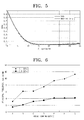
- Figure 5 shows an example of modelling SFR P using a spline function. As shown in Figure 5 , a thin line indicates SFR P calculated by the SFR P calculation unit 242, and a thick line indicates the modeled SFR P .
- the setting unit 260 sets the principal frequency of SFR P using the modeled SFR P as shown in Figure 5 .
- the setting unit 260 confirms the frequency corresponding to the principal SFR P among the modeled SFR P s through a graph as shown in Figure 5 , and sets the confirmed frequency as the principal frequency of SFR P .
- the principal SFR P may be a value of one among SFR P s in the graph as shown in Figure 4C or Figure 5 . Since the difference between frequencies corresponding to SFRs of plural image forming devices SFR P s becomes greater as the principal SFR P approaches 0, an SFR P near 0 may be set as the principal SFR P .
- Figure 6 shows an example of principal frequencies set from a plurality of modeled SFR P s of image forming devices when "0.1" and "0.5" are set as principal SFR P s.
- a ⁇ G denote image forming devices.
- the principal frequency which is a frequency corresponding to the principal SFR P , refers to the number of cycles located in 1mm, where one white pixel and one black pixel constitute one cycle. Since dpi is based on inches, the principal frequency is multiplied by 25.4 in order to calculate the principal frequency in terms of inches.
- the control unit 280 controls the whole operation of the resolution calculating apparatus 200 according to the programs stored in the storage unit 210.
- the control unit 280 provides luminance values of pixels corresponding to the region, for example, the region 31, selected from the test chart to the SFR M calculation unit 241, and provides SFR S of the scanner (not illustrated) stored in the storage unit 210 to the SFR P calculation unit 242.
- the resolution (dpi) calculated by Equation (1) indicate not only the existing physical resolution but also the sharpness of the edge. For example, if the resolution calculated by the judgment unit 270 is 615dpi when the image forming device prints the test chart with the resolution of 600dpi, it means that the 600 pixels are printed in one inch with the edge processed more sharply. Accordingly, by calculating the resolution reflecting the physical characteristics and the software characteristics through a frequency response of the test chart having black and white regions and edges, it is possible to indicate the sharpness of the edge that can be expressed in the image forming device through the calculated resolution.
- Figure 7 shows an example of the results of calculating and modelling a plurality of modeled SFR P s of image forming devices.
- Figure 8 shows an example of dpi calculated from a principal frequency corresponding to a principal SFR P among modeled SFR P s.
- A' ⁇ J' denote image forming devices
- SFR P means SFRs of the respective image forming devices.
- the designer prints the same test chart through the image forming devices A' ⁇ J', respectively, and scans the printed test charts through the same scanner (not illustrated).
- the calculation unit 240 calculates SFR P s of the respective image forming devices A' ⁇ J' from the respective scanned test charts.
- the modelling unit 250 performs modelling of SFR P s of the image forming devices A' ⁇ J' using a modelling function to output the results as shown in Figure 7 .
- Table 1 Image Forming Device Principal Frequency (cycles/mm) corresponding to 0.1SFR P Converted Resolution (dpi) A' 16.6 845 B' 15.9 806 C' 14.6 739 D' 12.9 653 E' 12.9 653 F' 12.7 643 G' 11.7 595 H' 11.5 586 I' 11.1 566 J' 10.0 518
- A' ⁇ J' denote image forming devices. Converted resolutions indicate the resolutions that reflect the edge characteristics calculated from the principal frequencies corresponding to 0.1 SFR P in Figure 7.
- Figure 8 shows a graph to which the data in Table 1 is applied.
- the image forming devices A' ⁇ J' print the test charts with the same physical resolution, for example, with the resolution of 600dpi.
- the resolutions calculated by reflecting the characteristics differ for the respective image forming devices A' ⁇ J'.
- the image forming process which has best processed the sharpness of the edge is A. Accordingly, in the case of calculating the resolution according to aspects of the present invention, not only the physical resolution but also the characteristic of the edge can be reflected, and thus more accurate resolution of the image forming device can be provided.
- one region is selected from a text chart displayed on the display unit 220, and the resolution that reflects the edge is calculated.
- the resolution calculating apparatus 200 may calculate the resolution by printing the digital data of the same test chart through one image forming device (not shown) several times.
- the scanned data of the printed test charts are stored in the storage unit 210, and the respective scanned test charts are displayed on the display unit 220.
- the designer may select regions having the same position or regions having different positions from the plural test charts being displayed on the display unit 220.
- the judgment unit 270 calculates the average of 10 principal frequencies obtained from SFR P s of the respective regions, and determines the calculated average value as the resolution that reflects the edge characteristic of the image forming device (not illustrated). When expressing the resolution in the unit of dpi, the judgment unit 270 calculates the average value in terms of dpi using Equation (1), and determines the calculated average value as the resolution that reflects the edge of the image forming device.
- the resolution calculating apparatus 200 may calculate the resolution that reflects the edge characteristic by selecting a plurality of regions from one test chart displayed on the display unit 220.
- Figure 9 shows an example of selecting a plurality of regions from a test charts.
- the designer may select a plurality of regions, e.g., 91 ⁇ 95 by manipulating the user input unit 230.
- the calculation unit 240 calculates SFR M s from the luminance values of the pixels located in the selected regions 91 ⁇ 95, and then calculates an average SFR M . Thereafter, the calculation unit 240 calculates one SFR P from the calculated average SFR M .
- the modelling unit 250 performs a modelling of the calculated SFR P as shown in Figure 5 .
- the setting unit 260 sets the principal frequency corresponding to the principal SFR P from SFR P .
- the judgment unit 270 judges the principal frequency as the resolution of the image forming device, or converts the resolution into dpi using Equation (1).
- the calculation unit 240 may calculate the respective SFR P s corresponding to the respective SFR M s, and then calculate the average value of the respective SFR P s.
- the modelling unit 250 then performs a modelling of the average SFR P .
- Figure 10 is a flowchart of a process of calculating a resolution of an image forming device according to an embodiment of the present invention.
- the designer generates a black/white test chart having a slanted edge, as shown in Figure 3 , and prints the test chart through the image forming device (not shown) at block S100.
- the printed test chart is scanned through a calibrated scanner, and the digital data of the scanned test chart, i.e., the digital data including luminance values of the respective pixels, is stored in the storage unit 210 at block S110.
- the designer displays the test chart on the display unit 220 by manipulating the user input unit 230. If at least one region that includes the edge is selected from the test chart at block S120, the control unit 280 reads the luminance values of the respective pixels that constitute the selected region ROI from the storage unit 210, and outputs the read luminance values to the SFR M calculation unit 241.
- the SFR M calculation unit 241 calculates SFR M from the luminance values of the selected region at block S130.
- the SFR M calculation unit 241 calculates the edge profile by calculating an average value of luminance of the respective line that is parallel to the direction of the edge with respect to the selected region, and calculates SFR M by converting the edge profile into a frequency domain.
- the SFR P calculation unit 242 compensates for SFR M using SFR S stored in the storage unit 210 and the calculated SFR M at block S140.
- the SFR P calculation unit 242 calculates SFR P .
- the modelling unit 250 performs a modelling of the SFR P using a modelling function as shown in Figure 5 at block S150.
- the setting unit 260 sets the frequency corresponding to the principal SFR P among the modeled SFR P s as the principal frequency of SFR P at block S160.
- the judgment unit 270 determines the principal frequency set at block S160 as the resolution of the image forming device (not illustrated) that reflects the sharpness of the edge, or converts the resolution in units of frequency into a resolution in units of dpi through Equation (1). Accordingly, the characteristic of the edge that is processed in the image forming device 9not illustrated), e.g., the resolution that reflects the sharpness, is calculated.
- the control unit 280 confirms whether all the principal frequencies corresponding to the selected regions are set at block S190. If plural test charts are printed through the same image forming device, the printed test charts are scanned at block S110, and at least one region that includes the edge is selected from the respective scanned test charts. The luminance values of the respective regions selected from the respective test charts are stored in the storage unit 210.
- control unit 280 reads the luminance values of the region located in the next test chart, in which the principal frequency is not set, from the storage unit 210, and provides the read luminance values to the SFR P calculation unit 241. Blocks S130 to S170 and block S190 are performed until the principal frequencies of the selected regions are all set.
- the judgment unit 270 calculates the average value of the principal frequencies and judges the average value as the resolution of the image forming device (not illustrated) at block S200. In addition, the judgment unit 270 converts the calculated average value into dpi using Equation (1) at block S210. Through the above-described process, the resolution of the image forming device that reflects the edge characteristic is calculated.
- the SFR M calculation unit 241 calculates SFR M s of the respective regions at block S130, and calculates an average SFR M of the respective SFR M s.
- the SFR P calculation unit 242 calculates SFR P using the average SFR M and SFR S calculated at block S140.
- the SFR P calculation unit 242 calculates the resolution that reflects the characteristic of the edge printed through the image forming device by performing blocks S150 to S180.
- the resolution calculating apparatus 200 comprises the display unit 220 and the user input unit 230.
- such construction is optional, not compulsory.
- the designer may select the region ROI that includes the edge from the connected computer, and the data that includes the luminance values of the selected region is transferred to the resolution calculating apparatus 200 to be stored in the storage unit 210. Thereafter, the system is automatically operated to calculate the resolution.
- the physical characteristic and the software characteristic of the resolution may be reflected by calculating the resolution that reflects the edge characteristic.
- the resolution is calculated using the test chart having a slanted edge to reflect the edge characteristic. Accordingly, the resolution calculating apparatus can calculate the resolution that reflects how sharply the edge of the image is printed in the image forming device.
- the designer can determine whether to adjust the resolution by grasping the edge characteristic from the calculated resolution of the image forming device, and apply aspects of the present invention to an image quality analyzing or image processing algorithm using the result of analysis, an edge processing algorithm, and the like.
- aspects of the present invention can also be embodied as computer readable codes on a computer readable recording medium.
- the computer readable recording medium is any data storage device that can store data which can be thereafter read by a computer system. Examples of the computer readable recording medium also include read-only memory (ROM), random-access memory (RAM), CD-ROMs, DVDs, magnetic tapes, floppy disks, and optical data storage devices.
- ROM read-only memory
- RAM random-access memory
- CD-ROMs compact discs
- DVDs digital versatile disks
- magnetic tapes magnetic tapes
- floppy disks floppy disks
- optical data storage devices optical data storage devices.
- the computer readable recording medium can also be distributed over network coupled computer systems so that the computer readable code is stored and executed in a distributed fashion.
- functional programs, codes, and code segments for accomplishing the present invention can be easily construed by programmers skilled in the art to which the present invention pertains.
- a method of determining a resolution may include calculating SFRs of the image forming device and determining the resolution of the image forming device using the principal SFR selected from the calculated SFRs.
- the apparatus to determine a resolution of the image forming device may include a controller to control the image forming device to print the test charts.
Landscapes
- Engineering & Computer Science (AREA)
- Multimedia (AREA)
- Signal Processing (AREA)
- Accessory Devices And Overall Control Thereof (AREA)
- Image Processing (AREA)
- Image Analysis (AREA)
- Control Or Security For Electrophotography (AREA)
Abstract
Description
- Aspects of the present invention relate to an apparatus and method of calculating a resolution, and, more particularly, to an apparatus and method of calculating a resolution that can reflect physical characteristics and performance characteristics of an image forming device by calculating a resolution that reflects a characteristic of an edge.
- An image forming device having a print function, such as a printer, a facsimile machine, and a multifunction device, forms an image on a printable medium using a mechanical engine, such as a laser scanning unit, a photoconductive drum, a developing roller, a feed roller, and the like. The resolution of the image formed on the printable medium is expressed by DPI (Dots Per Inch). DPI indicates the number of pixels or dots printed per inch. For example, a resolution of 600dpi indicates that the image forming device prints 600 pixels or dots per inch.
- The resolution of the printed image is affected by the mechanical engine or by a software algorithm, such as an algorithm to process the sharpness of an edge. Accordingly, the resolution and sharpness of images printed by image forming devices having the same resolution, e.g., 600dpi, may differ depending on their manufacturers, models, or print options.
-
Figures 1A and 1B show examples of printouts obtained from image forming devices having the same resolution. As shown inFigures 1A and 1B , although images printed with the same resolution through different image forming devices have the same resolution, the sharpness of edges and the sharpness of the images may differ. This is because the resolution used in conventional image forming devices reflects only the physical characteristics of the image forming devices, such as how many dots are printed in a region of one inch, but does not reflect how sharp the edge or line is in vision. Accordingly, in expressing the resolution of the images as shown inFigures 1A and 1B of the image forming device, there is a need to calculate and express a more accurate resolution through reflection of the degree of sharpness of an edge or line of a printed image. - Aspects of the present invention provide an apparatus and method of calculating a resolution, which can calculate the resolution that reflects the degree of sharpness of an edge existing in a printed image.
- Additional aspects and/or advantages of the invention will be set forth in part in the description which follows and, in part, will be obvious from the description, or may be learned by practice of the invention.
- According to an aspect of the present invention, a method of calculating a resolution is provided. The method comprises selecting a region having an edge from a test chart; calculating a spatial frequency response (SFR) of an image forming device that has printed the test chart using the selected region; setting a frequency corresponding to a principal SFR among the calculated SFRs of the image forming device as a principal frequency of the SFR of the image forming device; and determining the set principal frequency as the resolution of the image forming device.
- According to another aspect of the present invention, the resolution of the image forming device is determined by calculating the set principal frequency in terms of DPI (Dots Per Inch).
- According to another aspect of the present invention, the method further comprises scanning the printed test chart; wherein the region having the edge is selected from the scanned test chart.
- According to another aspect of the present invention, the calculating of the SFR of the image forming device comprises calculating an SFR of a scanner that has scanned the test chart; calculating an SFR of the selected region; and calculating the SFR of the image forming device using the SFR of the scanner and the SFR of the selected region.
- According to another aspect of the present invention, the step of calculating the SFR of the selected region may comprise calculating an average value of luminance of respective lines based on a direction in which the edge is formed with respect to the selected region; and obtaining the SFR of the selected region by converting the calculated average value of luminance into a frequency domain.
- According to another aspect of the present invention, the SFR of the image forming device is by dividing the SFR of the selected region by the SFR of the scanner.
- According to another aspect of the present invention, the method further comprises if plural test charts are printed, selecting regions that include the edge from the respective test charts; calculating the SFRs of the image forming device from the respective selected regions; setting the principal frequencies corresponding to the principal SFRs from the calculated SFRs of the image forming device; and calculating an average of the respective principal frequencies and determining the average as the resolution of the image forming device.
- According to another aspect of the present invention, the method further comprises if plural regions having the edge are selected from the test chart, calculating the SFRs of the image forming device from the respective selected regions; calculating an average of the calculated SFRs of the image forming device; setting the principal frequency corresponding to the principal SFR from the calculated average of the SFRs of the image forming device; and determining the set principal frequency as the resolution of the image forming device.
- According to another aspect of the present invention, the test chart is composed of a black space and a white space, and the edge may be formed on a boundary between the black space and the white space.
- According to another aspect of the present invention, the edge is formed in a direction of a slanted line.
- According to another aspect of the present invention, the method further comprises removing noise by modelling the calculated SFR of the image forming device.
- According to another aspect of the present invention, the principal SFR is the SFR that approaches 0 among the SFRs of the image forming device normalized to be in the range of 0~1.
- According to another aspect of the present invention, an apparatus to calculate a resolution of an image forming device is provided. The apparatus comprises a calculation unit to calculate a spatial frequency response (SFR) of the image forming device that has printed a test chart from a selected region if the selected region has; a setting unit to set a frequency corresponding to a principal SFR among the calculated SFRs of the image forming device as a principal frequency of the SFR of the image forming device; and a judgment unit to determine the set principal frequency as the resolution of the image forming device.
- According to another aspect of the present invention, the judgment unit determines the resolution of the image forming device by calculating the set principal frequency in terms of DPI (Dots Per Inch).
- According to another aspect of the present invention, the calculation unit calculates an SFR of a scanner that has scanned the test chart and an SFR of the selected region, and calculates the SFR of the image forming device by dividing the SFR of the selected region by the SFR of the scanner.
- According to another aspect of the present invention, the calculation unit calculates an average value of luminance of respective lines based on a direction in which the edge is formed with respect to the selected region, and calculates the SFR of the selected region by converting the calculated average value of luminance into a frequency domain.
- According to another aspect of the present invention, the calculation unit calculates the SFRs of the image forming device from respective regions selected from plural test charts if the plural test charts are printed; the setting unit sets the principal frequencies corresponding to the principal SFRs from the calculated SFRs of the image forming device; and the judgment unit calculates an average of the respective principal frequencies and determines the average as the resolution of the image forming device.
- According to another aspect of the present invention, the calculation unit calculates the SFRs of the image forming device from plural regions if the plural regions having the edge are selected and calculates an average of the calculated SFRs of the image forming device; the setting unit sets the principal frequency corresponding to the principal SFR from the calculated average of the SFRs of the image forming device; and the judgment unit determines the set principal frequency as the resolution of the image forming device.
- According to another aspect of the present invention, the apparatus further comprises a modelling unit to removing noise by modelling the calculated SFR of the image forming device.
- Embodiments of the invention will now be described by way of example only, with reference to the accompanying drawings, of which:
-
Figures 1A and 1B illustrate examples of printouts obtained from image forming devices having the same resolution; -
Figure 2 is a block diagram illustrating the construction of an apparatus for calculating a resolution according to an embodiment of the present invention; -
Figure 3 illustrates an example of a test chart; -
Figure 4A illustrates an ideal example of an edge profile indicating an average value of luminance of a respective line; -
Figure 4B illustrates an actual example of an edge profile indicating an average value of luminance of a respective line; -
Figure 4C illustrates an example of SFRP that is an SFR of an image forming device located in a frequency domain calculated by an SFRP calculation unit; -
Figure 5 illustrates an example of modelling SFRP using a spline function; -
Figure 6 illustrates an example of principal frequencies set from a plurality of modeled SFRPs of image forming devices when "0.1" and "0.5" are set as principal SFRPs; -
Figure 7 illustrates an example of results of calculating and modelling a plurality of modeled SFRPs of image forming devices; -
Figure 8 illustrates an example of DPI calculated from a principal frequency that corresponds to a principal SFRP among modeled SFRPs; -
Figure 9 illustrates an example of selecting a plurality of regions from a test chart; and -
Figure 10 is a flowchart of a process of calculating a resolution of an image forming device according to an embodiment of the present invention. -
Figure 2 is a block diagram showing the construction of anapparatus 200 for calculating a resolution according to an embodiment of the present invention. Theresolution calculating apparatus 200 comprises astorage unit 210, adisplay unit 220, auser input unit 230, acalculation unit 240, amodelling unit 250, asetting unit 260, ajudgment unit 270, and acontrol unit 280. Theresolution calculating apparatus 200 calculates the resolution of an image forming device having a print function, which includes not only a physical characteristic indicating how many dots are printed per inch but also the sharpness of a line or an edge of a printed image. Examples of the image forming device include a printer, a facsimile machine, a multifunction device, and the like. According to other aspects of the invention, theresolution calculating apparatus 200 may contain additional and/or different units. Similarly, the functionality of two or more of the above units may be combined into a single component. - In order to calculate the resolution, as shown in
Figure 3 , a designer first produces a test chart composed of a black space and a white space, in which an edge of a slanted line is formed on a boundary between the black space and the white space. The designer produces a test chart having black digital data and white digital data. Although the edge is shown inFigure 3 as a slanted line, the slope of the edge may be set in the range of 0° to 360°. The test chart is an image designed to test the actual resolution reflecting inherent properties of the image forming device (not shown). Theapparatus 200 may be provided in the image forming device or may be provided separately. - The designer prints the test chart by transmitting digital data corresponding to the test chart to the image forming device, and then acquires a scanned test chart by scanning the printed test chart using a scanner (not shown). The digital data of the scanned test chart is stored in the
storage unit 210. - The image forming device prints the test chart with the existing resolutions of 600dpi, 1200dpi, and the like. In addition, a calibrated scanner is used as the scanner so that the resolution of the image forming device, which is measured by the
resolution calculating apparatus 200, is not affected by the scanner. The scanner may be provided in theresolution calculating apparatus 200 or may be provided separately. - The designer pre-calculates an SFR (Spatial Frequency Response) of the scanner (not illustrated), which is required to calculate the SFR of the image forming device to be described later, and stores the SFR of the scanner in the
storage unit 210. The SFR of the scanner is referred to as "SFRS". According to ISO 16067-1, which defines the standard related to the calculation of SFRS, SFRS is calculated by scanning a standardized chart called hard copy. Since this technique is known in the art, the detailed description thereof will be omitted. - The
resolution calculating apparatus 200 will be briefly described. Thecalculation unit 240, if a region having an edge is selected from a test chart, calculates the SFR of the image forming device that has printed the test chart from the selected region. The SFR of the image forming device is referred to as "SFRP". - The
setting unit 260 sets the frequency corresponding to the principal SFRP among the calculated SFRPs as the principal frequency of SFRP. Thejudgment unit 270 determines the set principal frequency as the resolution of the image forming device that reflects the sharpness of the edge. - The
storage unit 210 stores digital data of the test chart input from the scanner (not illustrated). The digital data of the test chart includes the positions and luminance values of respective pixels. Thestorage unit 210 stores programs required to drive and control theresolution calculating apparatus 200. - The
display unit 220 processes and displays the digital data of the test chart stored in thestorage unit 210. Accordingly, the test chart as shown inFigure 3 is displayed through thedisplay unit 220. - The
user input unit 230 is a user interface, such as a mouse, a keyboard, touchpad, microphone, buttons, or other device capable of receiving input from the user. The user selects at least one region of interest (ROI) including an edge from the test chart being displayed on thedisplay unit 220. For example, the designer, if he/she intends to calculate the resolution in a horizontal direction, selects aregion 31 having an edge that is nearly a vertical line. Similarly, to calculate the resolution in a vertical direction, the user selects aregion 32 having an edge that is nearly a horizontal line. - If a region having an edge is selected from the test chart being displayed, the
calculation unit 240 calculates SFRP of the image forming device (not shown) that has printed the test chart from the selected region. For example, thecalculation unit 240 may calculate SFRP using the luminance values of the respective pixels in the selected region. Thecalculation unit 240 comprises an SFRM calculation unit 241 and an SFRP calculation unit 242. - The SFRM calculation unit 241 calculates the average value of luminance of the respective line that is parallel to the direction of the edge based on a direction in which the edge is formed (e.g., a direction indicated by an arrow) with respect to the selected region.
Figure 4A shows an ideal example of an edge profile indicating an average value of luminance of a respective line, andFigure 4B shows an actual example of an edge profile indicating an average value of luminance of a respective line. The edge profile as shown inFigure 4B is a value calculated in a spatial domain. - The SFRM calculation unit 241 calculates the SFR of the selected region SFRM by converting the average value of the luminance of the respective line calculated in the spatial domain into a frequency domain. Specifically, the SFRM calculation unit 241 calculates the SFR of the selected region SFRM by performing a DFT (Discrete Fourier Transform) or FFT (Fast Fourier Transform) of the average value of the luminance of the respective line, i.e., the edge profile as shown in
Figure 4B . The calculated SFR of the selected region SFRM is inputted to the SFRP calculation unit 242. The SFR of the selected region is referred to as "SFRM". - The SFRP calculation unit 242 compensates for SFRS using SFRS stored in the
storage unit 210 and SFRM calculated by the SFRM calculation unit 241. The SFRP calculation unit 242 may calculate the SFRP using the following equation:
-
Figure 4C shows an example of the SFRP, the SFR of the image forming device located in a frequency domain calculated by the SFRP calculation unit 242. The SFR (Spatial Frequency Response) is a unit of resolution calculation, and is generally indicated as a graph of an output response to a unit amplitude input signal in a spatial frequency range. The SFR is normalized to have a value in the range of 0~1 in the spatial frequency. Accordingly, as shown inFigure 4C , the SFR of the image forming device SFRP has a value in the range of 0~1, and the unit of frequency F is cycles/mm. For example, if the frequency is 10, 10 cycles exist per mm, and the period is repeated ten times. - Returning to
Figure 2 , themodelling unit 250 performs a function modelling of SFRP in order to remove a noise of SFRP calculated by the SFRP calculation unit 242. For example, themodelling unit 250 may perform the modelling using a cubic spline function or a Cauchy function, although other functions may be used as well. -
Figure 5 shows an example of modelling SFRP using a spline function. As shown inFigure 5 , a thin line indicates SFRP calculated by the SFRP calculation unit 242, and a thick line indicates the modeled SFRP. - The
setting unit 260 sets the principal frequency of SFRP using the modeled SFRP as shown inFigure 5 . Thesetting unit 260 confirms the frequency corresponding to the principal SFRP among the modeled SFRPs through a graph as shown inFigure 5 , and sets the confirmed frequency as the principal frequency of SFRP. - The principal SFRP may be a value of one among SFRPs in the graph as shown in
Figure 4C orFigure 5 . Since the difference between frequencies corresponding to SFRs of plural image forming devices SFRPs becomes greater as the principal SFRP approaches 0, an SFRP near 0 may be set as the principal SFRP. -
Figure 6 shows an example of principal frequencies set from a plurality of modeled SFRPs of image forming devices when "0.1" and "0.5" are set as principal SFRPs. InFigure 6 , A~G denote image forming devices. Principal frequencies shown by ◆ indicate frequencies corresponding to principal SFRp = 0.1 among the modeled SFRPs of the image forming devices A~G, and principal frequencies shown by ■ indicate frequencies corresponding to principal SFRp = 0.5. As shownFigure 6 , when the principal SFRP = 0.1, rather than the principal SFRp =0.5, the difference between the principal frequencies becomes greater. - Turning again to
Figure 2 , thejudgment unit 270 determines the principal frequency set by thesetting unit 260 as the resolution of the image forming device (not shown) that reflects the sharpness of the edge. For example, if the principal SFRP is 0.1 and the corresponding principal frequency is 10 cycles/mm, thejudgment unit 270 judges that the resolution of the image forming device is 10 cycles/mm. When expressing the resolution of the image forming device in units of dpi, thejudgment unit 270 may use Equation (1) below.
- Referring to Equation (1), the principal frequency, which is a frequency corresponding to the principal SFRP, refers to the number of cycles located in 1mm, where one white pixel and one black pixel constitute one cycle. Since dpi is based on inches, the principal frequency is multiplied by 25.4 in order to calculate the principal frequency in terms of inches.
- The
control unit 280 controls the whole operation of theresolution calculating apparatus 200 according to the programs stored in thestorage unit 210. For example, thecontrol unit 280 provides luminance values of pixels corresponding to the region, for example, theregion 31, selected from the test chart to the SFRM calculation unit 241, and provides SFRS of the scanner (not illustrated) stored in thestorage unit 210 to the SFRP calculation unit 242. - The resolution (dpi) calculated by Equation (1) indicate not only the existing physical resolution but also the sharpness of the edge. For example, if the resolution calculated by the
judgment unit 270 is 615dpi when the image forming device prints the test chart with the resolution of 600dpi, it means that the 600 pixels are printed in one inch with the edge processed more sharply. Accordingly, by calculating the resolution reflecting the physical characteristics and the software characteristics through a frequency response of the test chart having black and white regions and edges, it is possible to indicate the sharpness of the edge that can be expressed in the image forming device through the calculated resolution. -
Figure 7 shows an example of the results of calculating and modelling a plurality of modeled SFRPs of image forming devices.Figure 8 shows an example of dpi calculated from a principal frequency corresponding to a principal SFRP among modeled SFRPs. - As shown in
Figures 7 and 8 , A'~J' denote image forming devices, and SFRP means SFRs of the respective image forming devices. In order to obtain the graph as shown inFigure 7 , the designer prints the same test chart through the image forming devices A'~J', respectively, and scans the printed test charts through the same scanner (not illustrated). Thecalculation unit 240 calculates SFRPs of the respective image forming devices A'~J' from the respective scanned test charts. - The
modelling unit 250 performs modelling of SFRPs of the image forming devices A'~J' using a modelling function to output the results as shown inFigure 7 . - Table 1 below shows principal frequencies corresponding to principal SFRP = 0.1 acquired from the results of modelling as shown in
Figure 7 and converted resolutions of the principal frequencies.Table 1: Image Forming Device Principal Frequency (cycles/mm) corresponding to 0.1SFRP Converted Resolution (dpi) A' 16.6 845 B' 15.9 806 C' 14.6 739 D' 12.9 653 E' 12.9 653 F' 12.7 643 G' 11.7 595 H' 11.5 586 I' 11.1 566 J' 10.0 518 - Referring to Table 1, A'~J' denote image forming devices. Converted resolutions indicate the resolutions that reflect the edge characteristics calculated from the principal frequencies corresponding to 0.1 SFRP in
Figure 7. Figure 8 shows a graph to which the data in Table 1 is applied. The image forming devices A'~J' print the test charts with the same physical resolution, for example, with the resolution of 600dpi. - As can be seen from Table 1 and
Figure 8 , the resolutions calculated by reflecting the characteristics (such as sharpness of the edge) differ for the respective image forming devices A'~J'. The image forming process which has best processed the sharpness of the edge is A. Accordingly, in the case of calculating the resolution according to aspects of the present invention, not only the physical resolution but also the characteristic of the edge can be reflected, and thus more accurate resolution of the image forming device can be provided. - According to aspects of the present invention, one region is selected from a text chart displayed on the
display unit 220, and the resolution that reflects the edge is calculated. In addition, theresolution calculating apparatus 200 may calculate the resolution by printing the digital data of the same test chart through one image forming device (not shown) several times. In this case, the scanned data of the printed test charts are stored in thestorage unit 210, and the respective scanned test charts are displayed on thedisplay unit 220. The designer may select regions having the same position or regions having different positions from the plural test charts being displayed on thedisplay unit 220. - For example, when 10 test charts are printed, 10 regions including the edge are selected, and thus the
calculation unit 240, themodelling unit 250, and thesetting unit 260 perform the above-describedoperation 10 times in order to obtain the principal frequencies from the selected region. Thejudgment unit 270 calculates the average of 10 principal frequencies obtained from SFRPs of the respective regions, and determines the calculated average value as the resolution that reflects the edge characteristic of the image forming device (not illustrated). When expressing the resolution in the unit of dpi, thejudgment unit 270 calculates the average value in terms of dpi using Equation (1), and determines the calculated average value as the resolution that reflects the edge of the image forming device. - As another example, the
resolution calculating apparatus 200 may calculate the resolution that reflects the edge characteristic by selecting a plurality of regions from one test chart displayed on thedisplay unit 220.Figure 9 shows an example of selecting a plurality of regions from a test charts. When the test chart as shown inFigure 9 is displayed on thedisplay unit 220, the designer may select a plurality of regions, e.g., 91~95 by manipulating theuser input unit 230. - The
calculation unit 240 calculates SFRMs from the luminance values of the pixels located in the selectedregions 91~95, and then calculates an average SFRM. Thereafter, thecalculation unit 240 calculates one SFRP from the calculated average SFRM. - The
modelling unit 250 performs a modelling of the calculated SFRP as shown inFigure 5 . Thesetting unit 260 sets the principal frequency corresponding to the principal SFRP from SFRP. Thejudgment unit 270 judges the principal frequency as the resolution of the image forming device, or converts the resolution into dpi using Equation (1). Thecalculation unit 240 may calculate the respective SFRPs corresponding to the respective SFRMs, and then calculate the average value of the respective SFRPs. Themodelling unit 250 then performs a modelling of the average SFRP. -
Figure 10 is a flowchart of a process of calculating a resolution of an image forming device according to an embodiment of the present invention. Referring toFigures 2 to 10 , the designer generates a black/white test chart having a slanted edge, as shown inFigure 3 , and prints the test chart through the image forming device (not shown) at block S100. The printed test chart is scanned through a calibrated scanner, and the digital data of the scanned test chart, i.e., the digital data including luminance values of the respective pixels, is stored in thestorage unit 210 at block S110. - The designer displays the test chart on the
display unit 220 by manipulating theuser input unit 230. If at least one region that includes the edge is selected from the test chart at block S120, thecontrol unit 280 reads the luminance values of the respective pixels that constitute the selected region ROI from thestorage unit 210, and outputs the read luminance values to the SFRM calculation unit 241. - The SFRM calculation unit 241 calculates SFRM from the luminance values of the selected region at block S130. The SFRM calculation unit 241 calculates the edge profile by calculating an average value of luminance of the respective line that is parallel to the direction of the edge with respect to the selected region, and calculates SFRM by converting the edge profile into a frequency domain. The SFRP calculation unit 242 compensates for SFRM using SFRS stored in the
storage unit 210 and the calculated SFRM at block S140. The SFRP calculation unit 242 calculates SFRP. - The
modelling unit 250 performs a modelling of the SFRP using a modelling function as shown inFigure 5 at block S150. Thesetting unit 260 sets the frequency corresponding to the principal SFRP among the modeled SFRPs as the principal frequency of SFRP at block S160. - If one region is selected, then at block S170 the
judgment unit 270 determines the principal frequency set at block S160 as the resolution of the image forming device (not illustrated) that reflects the sharpness of the edge, or converts the resolution in units of frequency into a resolution in units of dpi through Equation (1). Accordingly, the characteristic of the edge that is processed in the image forming device 9not illustrated), e.g., the resolution that reflects the sharpness, is calculated. - If plural regions are selected, that is, if plural test charts are printed through the same image forming device and the region ROI is selected from the respective test charts, the
control unit 280 confirms whether all the principal frequencies corresponding to the selected regions are set at block S190. If plural test charts are printed through the same image forming device, the printed test charts are scanned at block S110, and at least one region that includes the edge is selected from the respective scanned test charts. The luminance values of the respective regions selected from the respective test charts are stored in thestorage unit 210. - If plural principal frequencies are not set, the
control unit 280 reads the luminance values of the region located in the next test chart, in which the principal frequency is not set, from thestorage unit 210, and provides the read luminance values to the SFRP calculation unit 241. Blocks S130 to S170 and block S190 are performed until the principal frequencies of the selected regions are all set. - If the principal frequencies of the selected regions are all set from the respective test charts, the
judgment unit 270 calculates the average value of the principal frequencies and judges the average value as the resolution of the image forming device (not illustrated) at block S200. In addition, thejudgment unit 270 converts the calculated average value into dpi using Equation (1) at block S210. Through the above-described process, the resolution of the image forming device that reflects the edge characteristic is calculated. - If plural regions are selected as shown in
Figure 9 , the SFRM calculation unit 241 calculates SFRMs of the respective regions at block S130, and calculates an average SFRM of the respective SFRMs. The SFRP calculation unit 242 calculates SFRP using the average SFRM and SFRS calculated at block S140. The SFRP calculation unit 242 calculates the resolution that reflects the characteristic of the edge printed through the image forming device by performing blocks S150 to S180. - According to aspects of the present invention, the
resolution calculating apparatus 200 comprises thedisplay unit 220 and theuser input unit 230. However, such construction is optional, not compulsory. For example, if a scanner (not shown) is connected to another computer, the designer may select the region ROI that includes the edge from the connected computer, and the data that includes the luminance values of the selected region is transferred to theresolution calculating apparatus 200 to be stored in thestorage unit 210. Thereafter, the system is automatically operated to calculate the resolution. - According to the apparatus and method of calculating a resolution according to aspects the present invention, the physical characteristic and the software characteristic of the resolution may be reflected by calculating the resolution that reflects the edge characteristic. Particularly, according to aspects of the present invention, the resolution is calculated using the test chart having a slanted edge to reflect the edge characteristic. Accordingly, the resolution calculating apparatus can calculate the resolution that reflects how sharply the edge of the image is printed in the image forming device.
- In addition, the designer can determine whether to adjust the resolution by grasping the edge characteristic from the calculated resolution of the image forming device, and apply aspects of the present invention to an image quality analyzing or image processing algorithm using the result of analysis, an edge processing algorithm, and the like.
- In addition, aspects of the present invention can also be embodied as computer readable codes on a computer readable recording medium. The computer readable recording medium is any data storage device that can store data which can be thereafter read by a computer system. Examples of the computer readable recording medium also include read-only memory (ROM), random-access memory (RAM), CD-ROMs, DVDs, magnetic tapes, floppy disks, and optical data storage devices. The computer readable recording medium can also be distributed over network coupled computer systems so that the computer readable code is stored and executed in a distributed fashion. Also, functional programs, codes, and code segments for accomplishing the present invention can be easily construed by programmers skilled in the art to which the present invention pertains.
- While there have been illustrated and described what are considered to be embodiments of the present invention, it will be understood by those skilled in the art and as technology develops that various changes and modifications, may be made without departing from the scope of the present invention. Many modifications, permutations, additions and sub-combinations may be made to adapt the teachings of the present invention to a particular situation without departing from the scope thereof. For example, a method of determining a resolution may include calculating SFRs of the image forming device and determining the resolution of the image forming device using the principal SFR selected from the calculated SFRs. In addition, the apparatus to determine a resolution of the image forming device may include a controller to control the image forming device to print the test charts.
Claims (21)
- A method of determining a resolution of an image forming device, the method comprising:calculating spatial frequency responses SFRs of the image forming device using a selected region of a test chart printed by the image forming device;determining the resolution of the image apparatus based on a principal SFR selected from the calculated SFRs.
- The method according to claim 1, wherein the resolution of the image forming device is determined by calculating the set principal frequency in terms of Dots Per Inch DPI.
- The method according to claim 1, further comprising:scanning the printed test chart;wherein a region having an edge is selected from the scanned test chart.
- The method according to claim 3, wherein the calculating of the SFR of the image forming device comprises:calculating an SFR of a scanner that has scanned the test chart;calculating an SFR of the selected region; andcalculating the SFR of the image forming device using the SFR of the scanner and the SFR of the selected region.
- The method according to claim 4, wherein the calculating of the SFR of the selected region comprises:calculating an average value of luminance of respective lines based on a direction in which the edge is formed with respect to the selected region; andobtaining the SFR of the selected region by converting the calculated average value of luminance into a frequency domain.
- The method according to claim 4, wherein the SFR of the image forming device is calculated by dividing the SFR of the selected region by the SFR of the scanner.
- The method according to claim 1, in which:the spatial frequency responses of the image forming apparatus are calculated using regions selected from a plurality of test charts printed by the image forming apparatus; andthe resolution is determined based on an average of the principal SFRs for each of the regions.
- The method according to claim 3, wherein the test chart is composed of a black space and a white space, and an edge is formed on a boundary between the black space and the white space.
- The method according to claim 8, wherein the edge is formed in a direction of a slanted line.
- The method according to claim 1, further comprising removing noise by modelling the calculated SFR of the image forming device.
- The method according to claim 1, wherein the principal SFR is the SFR that approaches 0 among the SFRs of the image forming device normalized to be in the range of 0~1.
- An apparatus for determining a resolution of an image forming device, the apparatus comprising:a calculation unit to calculate spatial frequency responses (SFR) of the image forming device using a selected region of a test chart printed by the image forming device; anda resolution determining unit to determine the resolution of the image forming device based on a principal SFR of the calculated SFRs.
- The apparatus according to claim 12, wherein the resolution determining unit is arranged to determine the resolution of the image forming device by calculating the set principal frequency in terms of DPI (Dots Per Inch).
- The apparatus according to claim 12, wherein the selected region having an edge is selected from an image acquired by scanning the printed test chart.
- The apparatus according to claim 14, wherein the calculation unit is arranged to calculate an SFR of a scanner that has scanned the test chart and an SFR of the selected region, and to calculate the SFR of the image forming device by dividing the SFR of the selected region by the SFR of the scanner.
- The apparatus according to claim 15, further comprising:a controller to control the image forming device to print the test chart.
- The apparatus according to claim 16, wherein:the controller is arranged to control the image forming device to print a plurality of test charts;the calculation unit is arranged to calculate the spatial frequency responses using a plurality of selected regions selected from the plurality of test charts; andthe resolution determining unit is arranged to determine the resolution based on an average of principal SFRs of calculated SFRs for each of the plurality of regions.
- The apparatus according to claim 15, wherein the calculation unit is arranged to calculate an average value of luminance of respective lines based on a direction in which the edge is formed with respect to the selected region, and then to calculate the SFR of the selected region by converting the calculated average value of luminance into a frequency domain.
- The apparatus according to claim 14, wherein the test chart is composed of a black space and a white space, and the edge is formed on a boundary between the black space and the white space.
- The apparatus according to claim 19, wherein the edge is a slanted line.
- The apparatus according to claim 12, further comprising a modelling unit to remove noise by modelling the calculated SFR of the image forming device.
Applications Claiming Priority (1)
| Application Number | Priority Date | Filing Date | Title |
|---|---|---|---|
| KR20070070116 | 2007-07-12 |
Publications (3)
| Publication Number | Publication Date |
|---|---|
| EP2015559A2 true EP2015559A2 (en) | 2009-01-14 |
| EP2015559A3 EP2015559A3 (en) | 2010-12-22 |
| EP2015559B1 EP2015559B1 (en) | 2017-06-07 |
Family
ID=39493448
Family Applications (1)
| Application Number | Title | Priority Date | Filing Date |
|---|---|---|---|
| EP08103126.2A Ceased EP2015559B1 (en) | 2007-07-12 | 2008-03-28 | Method and apparatus for calculating resolution |
Country Status (4)
| Country | Link |
|---|---|
| US (1) | US8547590B2 (en) |
| EP (1) | EP2015559B1 (en) |
| KR (1) | KR101213697B1 (en) |
| CN (1) | CN101345811A (en) |
Families Citing this family (4)
| Publication number | Priority date | Publication date | Assignee | Title |
|---|---|---|---|---|
| CN105203302A (en) * | 2015-09-15 | 2015-12-30 | 歌尔声学股份有限公司 | Resolution detecting method and resolution detecting device |
| CN106558044B (en) * | 2015-09-29 | 2019-12-31 | 宁波舜宇光电信息有限公司 | Resolution measurement method of image module |
| WO2017173501A1 (en) * | 2016-04-08 | 2017-10-12 | Lbt Innovations Limited | Method and system for validating resolvable detail across a depth of field |
| CN106846352B (en) * | 2016-12-30 | 2019-12-27 | 歌尔科技有限公司 | Knife edge picture acquisition method and device for lens analysis force test |
Family Cites Families (7)
| Publication number | Priority date | Publication date | Assignee | Title |
|---|---|---|---|---|
| EP1280333A1 (en) | 2001-07-24 | 2003-01-29 | Imip Llc | Automatic image quality determination |
| US7079704B2 (en) * | 2002-06-26 | 2006-07-18 | Koninklijke Philips Electronics N.V. | Objective method and system for estimating perceived image and video sharpness |
| US7634575B2 (en) * | 2003-10-09 | 2009-12-15 | Hewlett-Packard Development Company, L.P. | Method and system for clustering data streams for a virtual environment |
| JP2006129405A (en) | 2004-11-01 | 2006-05-18 | Ricoh Co Ltd | Color image density measuring method and apparatus and recording medium |
| US7593603B1 (en) * | 2004-11-30 | 2009-09-22 | Adobe Systems Incorporated | Multi-behavior image correction tool |
| KR100844144B1 (en) * | 2005-08-19 | 2008-07-04 | 삼성전자주식회사 | Image processing apparatus and method thereof for evaluating image quality |
| KR100669251B1 (en) | 2005-11-25 | 2007-01-16 | 한국전자통신연구원 | Digital image quality automatic analysis device and method |
-
2007
- 2007-12-10 US US11/953,225 patent/US8547590B2/en not_active Expired - Fee Related
-
2008
- 2008-02-15 KR KR1020080014084A patent/KR101213697B1/en not_active Expired - Fee Related
- 2008-03-28 EP EP08103126.2A patent/EP2015559B1/en not_active Ceased
- 2008-05-05 CN CNA2008100953844A patent/CN101345811A/en active Pending
Non-Patent Citations (5)
| Title |
|---|
| Anonymous: "Optical resolution"[Online] 16 September 2006 (2006-09-16), XP002601267 Wikipedia, the free encyclopedia Retrieved from the Internet: URL:http://en.wikipedia.org/wiki/Optical_resolutionSystem_resolution> [retrieved on 2010-09-16] * |
| Paul M. Hubel ET AL: "<title>Spatial frequency response of color image sensors: Bayer color filters and Foveon X3</title>", Proceedings of SPIE, vol. 5301, 7 June 2004 (2004-06-07), pages 402-407, XP055101014, ISSN: 0277-786X, DOI: 10.1117/12.561568 * |
| Peter Burns: "sfrmat 2.0 User's Guide"[Online] 12 August 2003 (2003-08-12), XP002601268 Retrieved from the Internet: URL:http://citeseerx.ist.psu.edu/viewdoc/download?doi=10.1.1.105.909&rep=rep1&type=pdf> [retrieved on 2010-09-08] * |
| Peter D. Burns and Don Willams: "Refined slanted-edge measurement practical camera and scanner testing" IS&T PICS Conference, [Online] 1 April 2002 (2002-04-01), pages 191-195, XP002601266 Retrieved from the Internet: URL:http://www.losburns.com/imaging/pbpubs/33pics2002b> [retrieved on 2010-09-16] * |
| Peter D. Burns: "Slanted-Edge MTF for Digital Camera and Scanner Analysis"[Online] 1 March 2000 (2000-03-01), XP002601269 Retrieved from the Internet: URL:http://citeseerx.ist.psu.edu/viewdoc/download?doi=10.1.1.149.2643&rep=rep1&type=pdf> [retrieved on 2010-09-16] * |
Also Published As
| Publication number | Publication date |
|---|---|
| EP2015559A3 (en) | 2010-12-22 |
| CN101345811A (en) | 2009-01-14 |
| US8547590B2 (en) | 2013-10-01 |
| EP2015559B1 (en) | 2017-06-07 |
| KR20090006715A (en) | 2009-01-15 |
| US20090015848A1 (en) | 2009-01-15 |
| KR101213697B1 (en) | 2013-01-09 |
Similar Documents
| Publication | Publication Date | Title |
|---|---|---|
| EP2149860B1 (en) | Image processing unit, noise reduction method, program, and storage medium | |
| US9007658B2 (en) | Inspection apparatus, inspection method, and program | |
| JP4912270B2 (en) | Image processing apparatus and control method thereof | |
| JP3327617B2 (en) | Image processing apparatus using halftone adaptive scanning to obtain good printable images | |
| EP2552097A2 (en) | Image processing apparatus, system, and method | |
| JP2003123055A (en) | Image inspection device | |
| JP5760785B2 (en) | Image processing apparatus and image processing system | |
| JP2013223039A (en) | Image processing device and image processing system and program | |
| EP2015559B1 (en) | Method and apparatus for calculating resolution | |
| US9942445B2 (en) | Image processing apparatus and image processing method | |
| US10432809B2 (en) | Reading apparatus and image generation method | |
| US8330997B2 (en) | Image processing apparatus, image forming apparatus and image processing method | |
| US7161706B2 (en) | System for improving digital coplers and multifunction peripheral devices | |
| JP5906924B2 (en) | Image processing apparatus, image processing system, and program | |
| JP5146942B2 (en) | CONVERSION METHOD, DEVICE, AND COMPUTER PROGRAM FOR CONVERTING DIGITAL IMAGE OBTAINED BY SCANNER | |
| US20240265523A1 (en) | Inspection apparatus, inspection system, and inspection method | |
| JP2012095173A (en) | Image processing device, image formation device, and image processing method | |
| JP2007129652A (en) | Image evaluation device | |
| JP3954268B2 (en) | Image reading device | |
| US20080170265A1 (en) | Image processing device, image forming apparatus, image forming system, image processing method and computer readable medium | |
| JP5434525B2 (en) | Image processing apparatus, calibration method, program, and recording medium | |
| JP4091174B2 (en) | Image processing apparatus and image processing method | |
| JP2004145634A (en) | Image processing apparatus and image processing method | |
| JP6632303B2 (en) | Image processing apparatus and image processing method | |
| JP4887320B2 (en) | Image processing device |
Legal Events
| Date | Code | Title | Description |
|---|---|---|---|
| PUAI | Public reference made under article 153(3) epc to a published international application that has entered the european phase |
Free format text: ORIGINAL CODE: 0009012 |
|
| AK | Designated contracting states |
Kind code of ref document: A2 Designated state(s): AT BE BG CH CY CZ DE DK EE ES FI FR GB GR HR HU IE IS IT LI LT LU LV MC MT NL NO PL PT RO SE SI SK TR |
|
| AX | Request for extension of the european patent |
Extension state: AL BA MK RS |
|
| RIC1 | Information provided on ipc code assigned before grant |
Ipc: H04N 1/60 20060101ALI20100922BHEP Ipc: H04N 1/409 20060101AFI20080710BHEP |
|
| PUAL | Search report despatched |
Free format text: ORIGINAL CODE: 0009013 |
|
| AK | Designated contracting states |
Kind code of ref document: A3 Designated state(s): AT BE BG CH CY CZ DE DK EE ES FI FR GB GR HR HU IE IS IT LI LT LU LV MC MT NL NO PL PT RO SE SI SK TR |
|
| AX | Request for extension of the european patent |
Extension state: AL BA MK RS |
|
| 17P | Request for examination filed |
Effective date: 20110622 |
|
| AKX | Designation fees paid |
Designated state(s): DE FR GB NL |
|
| RAP1 | Party data changed (applicant data changed or rights of an application transferred) |
Owner name: SAMSUNG ELECTRONICS CO., LTD. |
|
| 17Q | First examination report despatched |
Effective date: 20140213 |
|
| GRAP | Despatch of communication of intention to grant a patent |
Free format text: ORIGINAL CODE: EPIDOSNIGR1 |
|
| STAA | Information on the status of an ep patent application or granted ep patent |
Free format text: STATUS: GRANT OF PATENT IS INTENDED |
|
| RAP1 | Party data changed (applicant data changed or rights of an application transferred) |
Owner name: S-PRINTING SOLUTION CO., LTD. |
|
| INTG | Intention to grant announced |
Effective date: 20170301 |
|
| GRAS | Grant fee paid |
Free format text: ORIGINAL CODE: EPIDOSNIGR3 |
|
| GRAA | (expected) grant |
Free format text: ORIGINAL CODE: 0009210 |
|
| STAA | Information on the status of an ep patent application or granted ep patent |
Free format text: STATUS: THE PATENT HAS BEEN GRANTED |
|
| AK | Designated contracting states |
Kind code of ref document: B1 Designated state(s): DE FR GB NL |
|
| REG | Reference to a national code |
Ref country code: GB Ref legal event code: FG4D |
|
| GRAA | (expected) grant |
Free format text: ORIGINAL CODE: 0009210 |
|
| REG | Reference to a national code |
Ref country code: DE Ref legal event code: R096 Ref document number: 602008050547 Country of ref document: DE |
|
| REG | Reference to a national code |
Ref country code: NL Ref legal event code: FP |
|
| REG | Reference to a national code |
Ref country code: DE Ref legal event code: R097 Ref document number: 602008050547 Country of ref document: DE |
|
| PLBE | No opposition filed within time limit |
Free format text: ORIGINAL CODE: 0009261 |
|
| STAA | Information on the status of an ep patent application or granted ep patent |
Free format text: STATUS: NO OPPOSITION FILED WITHIN TIME LIMIT |
|
| 26N | No opposition filed |
Effective date: 20180308 |
|
| REG | Reference to a national code |
Ref country code: NL Ref legal event code: HC Owner name: HP PRINTING KOREA CO., LTD.; KR Free format text: DETAILS ASSIGNMENT: CHANGE OF OWNER(S), CHANGE OF OWNER(S) NAME; FORMER OWNER NAME: S-PRINTING SOLUTION CO., LTD. Effective date: 20180816 |
|
| REG | Reference to a national code |
Ref country code: DE Ref legal event code: R082 Ref document number: 602008050547 Country of ref document: DE Ref country code: DE Ref legal event code: R081 Ref document number: 602008050547 Country of ref document: DE Owner name: HP PRINTING KOREA CO., LTD., SUWON-SI, KR Free format text: FORMER OWNER: S-PRINTING SOLUTION CO., LTD., SUWON-SI, GYEONGGI-DO, KR Ref country code: DE Ref legal event code: R081 Ref document number: 602008050547 Country of ref document: DE Owner name: HEWLETT-PACKARD DEVELOPMENT COMPANY, L.P., SPR, US Free format text: FORMER OWNER: S-PRINTING SOLUTION CO., LTD., SUWON-SI, GYEONGGI-DO, KR Ref country code: DE Ref legal event code: R082 Ref document number: 602008050547 Country of ref document: DE Representative=s name: SCHOPPE, ZIMMERMANN, STOECKELER, ZINKLER, SCHE, DE |
|
| PG25 | Lapsed in a contracting state [announced via postgrant information from national office to epo] |
Ref country code: FR Free format text: LAPSE BECAUSE OF NON-PAYMENT OF DUE FEES Effective date: 20180331 |
|
| REG | Reference to a national code |
Ref country code: NL Ref legal event code: PD Owner name: HEWLETT-PACKARD DEVELOPMENT COMPANY, L.P.; US Free format text: DETAILS ASSIGNMENT: CHANGE OF OWNER(S), CHANGE OF LEGAL ENTITY; FORMER OWNER NAME: HP PRINTING KOREA CO., LTD. Effective date: 20191030 |
|
| REG | Reference to a national code |
Ref country code: DE Ref legal event code: R081 Ref document number: 602008050547 Country of ref document: DE Owner name: HEWLETT-PACKARD DEVELOPMENT COMPANY, L.P., SPR, US Free format text: FORMER OWNER: HP PRINTING KOREA CO., LTD., SUWON-SI, GYEONGGI-DO, KR |
|
| REG | Reference to a national code |
Ref country code: GB Ref legal event code: 732E Free format text: REGISTERED BETWEEN 20191212 AND 20191218 |
|
| REG | Reference to a national code |
Ref country code: DE Ref legal event code: R082 Ref document number: 602008050547 Country of ref document: DE Representative=s name: SCHOPPE, ZIMMERMANN, STOECKELER, ZINKLER, SCHE, DE |
|
| PGFP | Annual fee paid to national office [announced via postgrant information from national office to epo] |
Ref country code: GB Payment date: 20220228 Year of fee payment: 15 Ref country code: DE Payment date: 20210528 Year of fee payment: 15 |
|
| PGFP | Annual fee paid to national office [announced via postgrant information from national office to epo] |
Ref country code: NL Payment date: 20220322 Year of fee payment: 15 |
|
| REG | Reference to a national code |
Ref country code: DE Ref legal event code: R119 Ref document number: 602008050547 Country of ref document: DE |
|
| REG | Reference to a national code |
Ref country code: NL Ref legal event code: MM Effective date: 20230401 |
|
| GBPC | Gb: european patent ceased through non-payment of renewal fee |
Effective date: 20230328 |
|
| PG25 | Lapsed in a contracting state [announced via postgrant information from national office to epo] |
Ref country code: NL Free format text: LAPSE BECAUSE OF NON-PAYMENT OF DUE FEES Effective date: 20230401 |
|
| PG25 | Lapsed in a contracting state [announced via postgrant information from national office to epo] |
Ref country code: GB Free format text: LAPSE BECAUSE OF NON-PAYMENT OF DUE FEES Effective date: 20230328 |
|
| PG25 | Lapsed in a contracting state [announced via postgrant information from national office to epo] |
Ref country code: GB Free format text: LAPSE BECAUSE OF NON-PAYMENT OF DUE FEES Effective date: 20230328 Ref country code: DE Free format text: LAPSE BECAUSE OF NON-PAYMENT OF DUE FEES Effective date: 20231003 |