EP2015498B1 - Relaystations and methods for data retransmission in multihop relay wireless communication system - Google Patents
Relaystations and methods for data retransmission in multihop relay wireless communication system Download PDFInfo
- Publication number
- EP2015498B1 EP2015498B1 EP08006819.0A EP08006819A EP2015498B1 EP 2015498 B1 EP2015498 B1 EP 2015498B1 EP 08006819 A EP08006819 A EP 08006819A EP 2015498 B1 EP2015498 B1 EP 2015498B1
- Authority
- EP
- European Patent Office
- Prior art keywords
- data
- ack
- information
- resource region
- lower node
- Prior art date
- Legal status (The legal status is an assumption and is not a legal conclusion. Google has not performed a legal analysis and makes no representation as to the accuracy of the status listed.)
- Ceased
Links
- 238000004891 communication Methods 0.000 title claims description 62
- 238000000034 method Methods 0.000 title claims description 37
- 230000005540 biological transmission Effects 0.000 claims description 25
- 101000741965 Homo sapiens Inactive tyrosine-protein kinase PRAG1 Proteins 0.000 claims 12
- 102100038659 Inactive tyrosine-protein kinase PRAG1 Human genes 0.000 claims 12
- 238000010586 diagram Methods 0.000 description 19
- 238000001514 detection method Methods 0.000 description 4
- 230000001419 dependent effect Effects 0.000 description 3
- 238000013468 resource allocation Methods 0.000 description 3
- 230000003044 adaptive effect Effects 0.000 description 2
- 238000011017 operating method Methods 0.000 description 2
- 206010010099 Combined immunodeficiency Diseases 0.000 description 1
- 235000008694 Humulus lupulus Nutrition 0.000 description 1
- 238000001360 collision-induced dissociation Methods 0.000 description 1
- 230000001010 compromised effect Effects 0.000 description 1
- 238000010276 construction Methods 0.000 description 1
- 125000004122 cyclic group Chemical group 0.000 description 1
Images


Classifications
-
- H—ELECTRICITY
- H04—ELECTRIC COMMUNICATION TECHNIQUE
- H04L—TRANSMISSION OF DIGITAL INFORMATION, e.g. TELEGRAPHIC COMMUNICATION
- H04L1/00—Arrangements for detecting or preventing errors in the information received
- H04L1/12—Arrangements for detecting or preventing errors in the information received by using return channel
- H04L1/16—Arrangements for detecting or preventing errors in the information received by using return channel in which the return channel carries supervisory signals, e.g. repetition request signals
- H04L1/18—Automatic repetition systems, e.g. Van Duuren systems
- H04L1/1829—Arrangements specially adapted for the receiver end
- H04L1/1854—Scheduling and prioritising arrangements
-
- H—ELECTRICITY
- H04—ELECTRIC COMMUNICATION TECHNIQUE
- H04B—TRANSMISSION
- H04B7/00—Radio transmission systems, i.e. using radiation field
- H04B7/14—Relay systems
- H04B7/15—Active relay systems
- H04B7/155—Ground-based stations
- H04B7/15528—Control of operation parameters of a relay station to exploit the physical medium
-
- H—ELECTRICITY
- H04—ELECTRIC COMMUNICATION TECHNIQUE
- H04L—TRANSMISSION OF DIGITAL INFORMATION, e.g. TELEGRAPHIC COMMUNICATION
- H04L1/00—Arrangements for detecting or preventing errors in the information received
- H04L1/0078—Avoidance of errors by organising the transmitted data in a format specifically designed to deal with errors, e.g. location
- H04L1/0079—Formats for control data
- H04L1/0081—Formats specially adapted to avoid errors in the feedback channel
-
- H—ELECTRICITY
- H04—ELECTRIC COMMUNICATION TECHNIQUE
- H04L—TRANSMISSION OF DIGITAL INFORMATION, e.g. TELEGRAPHIC COMMUNICATION
- H04L1/00—Arrangements for detecting or preventing errors in the information received
- H04L1/12—Arrangements for detecting or preventing errors in the information received by using return channel
- H04L1/16—Arrangements for detecting or preventing errors in the information received by using return channel in which the return channel carries supervisory signals, e.g. repetition request signals
- H04L1/18—Automatic repetition systems, e.g. Van Duuren systems
- H04L1/1812—Hybrid protocols; Hybrid automatic repeat request [HARQ]
-
- H—ELECTRICITY
- H04—ELECTRIC COMMUNICATION TECHNIQUE
- H04L—TRANSMISSION OF DIGITAL INFORMATION, e.g. TELEGRAPHIC COMMUNICATION
- H04L5/00—Arrangements affording multiple use of the transmission path
- H04L5/003—Arrangements for allocating sub-channels of the transmission path
- H04L5/0053—Allocation of signaling, i.e. of overhead other than pilot signals
- H04L5/0055—Physical resource allocation for ACK/NACK
-
- H—ELECTRICITY
- H04—ELECTRIC COMMUNICATION TECHNIQUE
- H04L—TRANSMISSION OF DIGITAL INFORMATION, e.g. TELEGRAPHIC COMMUNICATION
- H04L1/00—Arrangements for detecting or preventing errors in the information received
- H04L2001/0092—Error control systems characterised by the topology of the transmission link
- H04L2001/0097—Relays
Definitions
- the BS 100 transmits the data destined for the MS 130 to the first RS 110.
- the second RS 120 sends a NACK message of the data to the first RS 110.
- the second RS 120 checks whether an ACK/NACK message is received from the MS 130 in a previous frame. When receiving the ACK/NACK message from the MS 130, the second RS 120 sends the ACK/NACK message of the data to the first RS 110 together with the ACK/NACK message from the MS 130.
- the first RS 202 sends an ACK/NACK message for data 1 to the BS 200 over the (i+1)-th frame 212.
- the BS 200 transmits data 5 to the first RS 202 in step 263.
- the first RS 202 checks for errors in data 5 received from the BS 200.
- the first RS 202 when data 4 is corrupted, the first RS 202 sends the NACK message for data 4 to the BS 200. Together with the NACK message for data 4, the first RS 202 forwards the ACK/NACK message received from the second RS 204 in the (i+3)-th frame 214, to the BS 200.
- the second RS 204 sends the ACK message for data 3 to the first RS 202 in step 271. Together with the ACK message for data 3, the second RS 204 forwards the ACK/NACK message received from the MS 206 over the (i+3)-th frame 216, to the first RS 202 in step 273.
- the second RS 204 when data 4 is corrupted, the second RS 204 sends the NACK message for data 4 to the first RS 202.
- the second RS 204 sends the ACK/NACK message received from the MS 206 over the (i+4)-th frame 218, to the first RS 202 together with the NACK message for data 4.
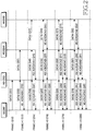
- FIGs. 3A and 3B are diagrams illustrating frame structures for carrying ACK/NACK scheduling information for the DL data in the multihop relay wireless communication system according to an embodiment of the present invention.
- the frame structure of the Institute of Electrical and Electronics Engineers (IEEE) 802.16 system is explained in FIGs. 3A and 3B by way of example.
- the BS allocates the control channels for sending the ACK/NACK messages according to the unique IDs of the first RS, the second RS, and the MS to the first RS through the UL-MAP.
- the BS defines a separate message or a separate IE so that the first RS can surely acquire the functions of the unique IDs of the second RS and the MS included in the UL-MAP, and informs the first RS of the usage of the unique ID of the second RS and the MS.
- the BS allocates the multi-channel for the ACK/NACK messages to the first RS using the UL-MAP of the DL subframe 320.
- the first RS can send the ACK/NACK message of the data received from the BS and the ACK/NACK message from the second RS or the MS, to the BS using the multi-channel at a time.
- the BS constitutes the UL-MAP including the IE for the ACK/NACK message of the RS so that the first RS can send the multi-ACK/NACK message.
- the IE for the ACK/NACK message of the RS includes information relating to the start point and the end point of the multi-ACK/NACK message.
- the BS can use the HARQ ACK region allocation IE of the IEEE 802.16 system as the IE for the ACK/NACK message.
- the start point and the end point of the ACK/NACK message are represented by the subchannel in the frequency domain and by the OFDM symbol in the time domain.
- the first RS transmits the ACK/NACK messages of the first RS, the second RS, and the MS to the BS through the multi-control channel allocated from the BS. In doing so, the BS and the first RS should agree on which data the ACK/NAC message sent through the multi-control channel pertains to.
- the wireless communication system transmits the ACK/NACK message for the UL data as shown in FIG. 4 .
- the first RS 402 Over the (i+5)-th frame 420, the first RS 402 sends an ACK/NACK message according to the error detection of data 1 received from the second RS 404. For instance, when data 1 is corrupted, the first RS 402 sends the NACK message for data 1 to the BS 400 and the second RS 402.
- the first RS 404 also sends the ACK/NACK message for data 1, which is received from the second RS 404 over the (i+4)-th frame 418, to the BS 400 in step 453.
- the first RS 402 transmits data 1 and the ACK message of data 1 to the BS 400 in step 451.
- the second RS 404 transmits data 2 and the ACK message of data 2 to the first RS 402 in step 457.
- the first RS 402 checks for errors in data 2 received from the second RS 404.
- the first RS 402 also sends the ACK/NACK message for data 2, which is received from the second RS 404 over the (i+5)-th frame 420, to the BS 400 in step 463.
- the IE indicates the start point and the end point of the region for the ACK/NACK message for each unique ID by the subchannel in the frequency domain and by the OFDM symbol in the time domain.
- the BS allocates the control channels for sending the ACK/NACK message based on the unique IDs of the first RS and the second RS, to the first RS through the UL-MAP.
- the BS defines a separate message so that the first RS can surely acquire the function of the unique ID of the second RS and the MS in the UL-MAP, and informs the first RS of the usage of the CID of the second RS and the MS.
- the BS constitutes an IE including the start point and the end point of the multi-ACK/NACK message and includes the IE to the UL-MAP so that the first RS can send the multiple ACK/NACK messages.
- the BS constitutes the IE for the ACK/NACK message using the HARQ region allocation IE of the IEEE 802.16 system.
- the start point and the end point of the ACK/NACK message in the UL frame are represented by the subchannel in the frequency domain and by the OFDM symbol in the time domain.
- step 601 the RS checks whether data is received. For instance, in the DL, the RS checks whether data is received from the upper node. In the UL, the RS checks whether data is received from the lower node.
- the RS When receiving no error occurrence information from the lower node, the RS transmits the error occurrence information of the received data to the upper node through the control channel provided from the upper node in step 611.
- the BS transmits the information of the determined nodes to the next-hop RS. For instance, the BS transmits the information of the determined nodes to the next-hop RS using the broadcasting information or the separate control channel.
- the fundamental unit of the data transmission in the wireless communication system is a frame. It is assumed that the frame is defined as a physical frame determined by taking into account the DL burst processing delay of the RS, the ACK feedback delay of the MS, and the ACK forwarding delay of the RS.
- the upper node allocates the control channel for the multi-ACK/NACK message to the lower node so that the lower node can send the multi-ACK/NACK message as shown in FIGs. 10A and 10B .
- the BS allocates the control channel for the multi-ACK/NACK message to the first RS, which is explained.
- the upper node of the multihop relay wireless communication system transmits the multi-control channel to the lower node for the control message for the data retransmission. Therefore, the RS can transmit the control messages for the ARQ provided from the lower nodes and the control messages for the ARQ of the RS, to the upper node at the same time.
Landscapes
- Engineering & Computer Science (AREA)
- Signal Processing (AREA)
- Computer Networks & Wireless Communication (AREA)
- Mobile Radio Communication Systems (AREA)
- Detection And Prevention Of Errors In Transmission (AREA)
- Communication Control (AREA)
Description
- The present invention relates generally to an apparatus and a method for an Automatic Retransmission reQuest (ARQ) in a wireless communication system, and more particularly, to an apparatus and a method for sending a control message for the ARQ in a multihop relay wireless communication system.
- In a wireless communication system, specific data may be corrupted according to a channel condition of a radio resource of the data. Error controlling and correcting methods largely include an Automatic Retransmission reQuest (ARQ) and a Forward Error Check (FEC). According to the ARQ, a receiver requests a transmitter to retransmit the corrupted data. The FEC scheme corrects errors in the compromised data at the receiver.
- When the wireless communication system adopts the ARQ scheme, the receiver checks for errors by decoding the received packets. When the received packets are free from error, the receiver sends an Acknowledgement (ACK) message to the transmitter.
- When errors are detected in the received packets, the receiver sends a Negative ACK (NACK) message to the transmitter.
- Upon receiving the ACK message from the receiver, the transmitter transmits new packets. Upon receiving the NACK message from the receiver, the transmitter retransmits the previous packets to the receiver.
- Recently, the wireless communication system provides a relay service using a relay station to provide a better radio channel to a mobile station, which travels in a cell boundary or in a shadow area. That is, the wireless relay communication system can provide a better radio channel between a base station and a mobile station by relaying data between the base station and the mobile station using the relay station.
- Thus, the wireless relay communication system requires an ARQ method using the relay station.
- International patent application
WO 2006/024320 A1 discloses an improved concept for reliably relaying a transmission from a sender to a receiver via one or multiple relay devices. Three different kinds of feedback messages ACK, RACK and NACK are used to provide feedback on the correct receipt of a data unit at the final destination, the correct receipt of a data unit at a relay station and a failed receipt of a data unit, respectively. - The IEEE draft "Pipeline HARQ for multi-relay system; C80216j-07_185r2", IEEE-SA, Piscataway, NJ, USA, vol. 802.16j, March 6, 2007 teaches a centralized scheduling method for multi-hop DL HARQ and UL HARQ, wherein the base station allocates the bandwidth for relaying ACK/NACK messages from each relay station and the mobile station towards the base station. The base station allocates one ACK channel for each relay station on the path, wherein the relay station forwards every received ACK/NACK message to the next station and to the destination base station.
- The present invention has been made to address at least the above-mentioned problems and/or disadvantages and to provide at least the advantages described below. The above advantages are achieved by providing operating methods of a Relay Station (RS) in a wireless relay communication system according to
claims 1 and 8. Preferred embodiments are subject of the dependent claims. - According to another aspect of the present invention, an operating method of an upper node in a wireless relay communication system according to claim 14 is provided. Preferred embodiments are subject of the dependent claims.
- According to an additional aspect of the present invention, relay stations in a wireless relay communication system according to claims 20 and 27 are provided. Preferred embodiments are subject of the dependent claims.
- The above and other aspects, features and advantages of the present invention will become more apparent from the following detailed description when taken in conjunction with the accompanying drawings, in which:
-
FIG. 1 is a diagram illustrating a multihop relay wireless communication system according to an embodiment of the present invention; -
FIG. 2 is a diagram illustrating a DownLink (DL) data transmission in the multihop relay wireless communication system according to an embodiment of the present invention; -
FIGs. 3A and 3B are diagrams illustrating frame structures for carrying ACK/NACK scheduling information for the DL data in the multihop relay wireless communication system according to an embodiment of the present invention; -
FIG. 4 is a diagram illustrating an UpLink (UL) data transmission in the multihop relay wireless communication system according to an embodiment of the present invention; -
FIGs. 5A and 5B are diagrams illustrating frame structures for carrying ACK/NACK scheduling information for the UL data in the multihop relay wireless communication system according to an embodiment of the present invention; -
FIG. 6 is a flow diagram illustrating operations of a Relay Station (RS) for the ARQ in the multihop relay wireless communication system according to an embodiment of the present invention; -
FIG. 7 is a flow diagram illustrating operations of a Base Station (BS) for the ARQ in the multihop relay wireless communication system according to an embodiment of the present invention; -
FIG. 8 is a diagram illustrating the RS in the multihop relay wireless communication system according to an embodiment of the present invention; -
FIG. 9 is a diagram illustrating a DL data transmission in a multihop relay wireless communication system according to an embodiment of the present invention; and -
FIGs. 10A and 10B are diagrams illustrating frame structures for carrying ACK/NACK scheduling information for the DL data in the multihop relay wireless communication system according to an embodiment of the present invention. - Preferred embodiments of the present invention are described in detail below with reference to the accompanying drawings. Detailed descriptions of constructions or processes known in the art may be omitted to avoid obscuring the subject matter of the present invention.
- The present invention provides a technique for transmitting a multi-control message for an Automatic Retransmission reQuest (ARQ) in a wireless relay communication system. While Acknowledgement (ACK)/Negative ACK (NACK) messages of the control messages are illustrated by way of example, the present invention is also applicable to other control messages.
- Hereinafter, an Orthogonal Frequency Division Multiple Access (OFDMA) wireless communication system is illustrated by way of example. Note that the present invention is also applicable to other multiple access communication systems.
- It is assumed that the wireless communication system includes three hops as shown in
FIG. 1 . Yet, the present invention is also applicable to a two-hop or multi-hop wireless communication system. -
FIG. 1 is a diagram illustrating a multihop relay wireless communication system according to an embodiment of the present invention. A first Relay Station (RS) 110 indicates a one-hop RS and asecond RS 120 indicates a two-hop RS. - In the wireless communication system of
FIG. 1 , a Base Station (BS) 100 services a Mobile Station (MS) 130 in its service coverage through a direct link. When the MS 130 travels in the outskirts of the service coverage or outside the service coverage of the BS 100, the BS 100 services the MS 130 using relay links via RSs 110 and 120. - For instance, to transmit data to the MS 130, the BS 100 transmits the data destined for the MS 130 to the first RS 110.
- Receiving the data from the
BS 100, thefirst RS 110 checks for errors in the data. For instance, the first RS 110 checks for errors using a Cyclic Redundancy Check (CRC) code of the data. - When the data is free of errors, the first RS 110 forwards the data to the
second RS 120. The first RS 110 also sends an ACK message for the data to theBS 100. By contrast, when an error is detected in the data, the first RS 110 sends a NACK message of the data to theBS 100. - The
first RS 110 checks whether ACK/NACK messages are received from lower nodes in a previous frame. When receiving the ACK/NACK messages from the lower nodes, thefirst RS 110 sends the ACK/NACK message of the data to theBS 100 together with the ACK/NACK messages from the lower nodes. Herein, the lower nodes indicate MSs in the service coverage of thefirst RS 110 or thesecond RS 120. - The
second RS 120, receiving the data from thefirst RS 110, checks whether the data has errors. When the data is free of errors, thesecond RS 120 forwards the data to theMS 130. Thesecond RS 120 sends an ACK message for the data to thefirst RS 110. - When an error is detected in the data, the
second RS 120 sends a NACK message of the data to thefirst RS 110. - The
second RS 120 checks whether an ACK/NACK message is received from theMS 130 in a previous frame. When receiving the ACK/NACK message from theMS 130, thesecond RS 120 sends the ACK/NACK message of the data to thefirst RS 110 together with the ACK/NACK message from theMS 130. - When receiving the data from the
second RS 120, theMS 130 checks whether the data has errors. When the data is free of errors, theMS 130 sends an ACK message of the data to thesecond RS 120. When an error is detected in the data, theMS 130 sends a NACK message of the data to thesecond RS 120. - As described above, the lower nodes in the wireless communication system send the ACK/NACK message to the upper node depending on the error occurrence of the received data. For example, as for a DownLink (DL), the nodes of the wireless communication system send the ACK/NACK message to the upper node as shown in
FIG. 2 . As for an UpLink (UL), the nodes of the wireless communication system send the ACK/NACK message to the upper node as shown inFIG. 4 . In doing so, the wireless communication system transmits and receives the data and the ACK/NACK message by a certain fundamental unit of the data transmission. Hereinafter, it is assumed that the fundamental unit of the data transmission is a frame in the wireless communication system. The frame indicates a Transmission Time Interval (TTI), which is the fundamental physical unit of the data transmission. In other words, the frame indicates the processing delay time taken for one node to receive the data, to check for errors, and to send the data and the ACK/NACK message. While it is assumed that the processing delay time is one frame, the processing delay time corresponding to the multiple frames may occur depending on the capabilities of the BS, the RS, and the MS. - The wireless communication system sends the ACK/NACK message for the DL data as shown in
FIG. 2 . -
FIG. 2 is a diagram illustrating a DL data transmission in the multihop relay wireless communication system according to an embodiment of the present invention. - To transmit data to an
MS 206, aBS 200 transmitsdata 1 to afirst RS 202 over the i-th frame 210 instep 231. Thefirst RS 202 checks for errors indata 1 received from theBS 200. - In
step 233, theBS 200 transmitsdata 2 to thefirst RS 202 over the (i+1)-th frame 212. Thefirst RS 202 checks for errors indata 2 received from theBS 200. - The
first RS 202 sends an ACK/NACK message fordata 1 to theBS 200 over the (i+1)-th frame 212. - For instance, when an error is detected in
data 1, thefirst RS 202 sends the NACK message for thedata 1 to theBS 200. - By contrast, when the
data 1 has no errors, thefirst RS 202 sends the ACK message fordata 1 to theBS 200 instep 235. Thefirst RS 202 forwards the error-free data 1 to thesecond RS 204 instep 237. Thesecond RS 204 checks for errors indata 1 received from thefirst RS 202. - The
BS 200 transmitsdata 3 to thefirst RS 202 over the (i+2)-th frame 214 instep 239. Thefirst RS 202 checks for errors indata 3 received from theBS 200. - Over the (i+2)-
th frame 214, thefirst RS 202 sends an ACK/NACK message fordata 2 to theBS 200. - For example, when
data 2 is corrupted, thefirst RS 202 sends the NACK message fordata 2 to theBS 200. - When
data 2 has no errors, thefirst RS 202 sends the ACK message fordata 2 to theBS 200 instep 241. Thefirst RS 202 forwards the error-free data 2 to thesecond RS 204 instep 243. Thesecond RS 204 checks for errors indata 2 received from thefirst RS 202. - In the (i+2)-
th frame 214, thesecond RS 204 sends an ACK/NACK message fordata 1 to thefirst RS 202. - For example, when an error is detected in
data 1, thesecond RS 204 sends the NACK message fordata 1 to thefirst RS 202. - When the
data 1 has no errors, thesecond RS 204 sends the ACK message fordata 1 to thefirst RS 202 instep 245. Thesecond RS 204 forwards the error-free data 1 to theMS 206 instep 247. TheMS 206 checks for errors indata 1 received from thesecond RS 204. - The
BS 200 transmitsdata 4 to thefirst RS 202 over the (i+3)-th frame 216 instep 249. Thefirst RS 202 checks for errors indata 4 received from theBS 200. - In the (i+3)-
th frame 216, thefirst RS 202 sends an ACK/NACK message fordata 3 to theBS 200. Together with the ACK/NACK message ofdata 3, thefirst RS 202 forwards the ACK/NACK message received from thesecond RS 204 over the (i+2)-th frame 214, to theBS 200 instep 253. - For example, when
data 3 is corrupted, thefirst RS 202 sends the NACK message to theBS 200 to request the retransmission ofdata 3. Together with the NACK message fordata 3, thefirst RS 202 forwards the ACK/NACK message received from thesecond RS 204 over the (i+2)-th frame 214, to theBS 200. - When the
data 3 has no errors, thefirst RS 202 sends the ACK message fordata 3 to theBS 200 instep 251. Together with the ACK ofdata 3, thefirst RS 202 forwards the ACK/NACK message received from thesecond RS 204 over the (i+2)-th frame 214, to theBS 200. - In
step 255, thefirst RS 202 forwards the error-free data 3 to thesecond RS 204. Thesecond RS 204 checks for errors indata 3 received from thefirst RS 202. - In the (i+3)-
th frame 216, thesecond RS 204 sends an ACK/NACK message fordata 2 to thefirst RS 202. - For instance, when
data 2 is corrupted, thesecond RS 204 sends the NACK message fordata 2 to thefirst RS 202. - When
data 2 is free from error, thesecond RS 204 sends the ACK message fordata 2 to thefirst RS 202 in step 257. Thesecond RS 204 forwards the error-free data 2 to theMS 206 instep 259. TheMS 206 checks for errors indata 2 received from thesecond RS 204. - In the (i+3)-
th frame 216, theMS 206 sends an ACK/NACK message fordata 1 to thesecond RS 204. - For example, when
data 1 is corrupted, theMS 206 sends the NACK message fordata 1 to thesecond RS 204. - When
data 1 is not corrupted at all, theMS 206 sends the ACK message fordata 1 to thesecond RS 204 instep 261. - In the (i+4)-
th frame 218, theBS 200 transmitsdata 5 to thefirst RS 202 instep 263. Thefirst RS 202 checks for errors indata 5 received from theBS 200. - The
first RS 202 sends an ACK/NACK message fordata 4 to theBS 200 in the (i+4)-th frame 218. Together with the ACK/NACK message fordata 4, thefirst RS 202 forwards the ACK/NACK message received from thesecond RS 204 over the (i+3)-th frame 214, to theBS 200 instep 267. - For example, when
data 4 is corrupted, thefirst RS 202 sends the NACK message fordata 4 to theBS 200. Together with the NACK message fordata 4, thefirst RS 202 forwards the ACK/NACK message received from thesecond RS 204 in the (i+3)-th frame 214, to theBS 200. - When
data 4 is not corrupted, thefirst RS 202 sends the ACK message fordata 4 to theBS 200 instep 265. Together with the ACK message fordata 4, thefirst RS 202 forwards the ACK/NACK message received from thesecond RS 204 over the (i+3)-th frame 216, to theBS 200. - The
first RS 202 forwards the error-free data 4 to thesecond RS 204 instep 269. Thesecond RS 204 checks for errors indata 4 received from thefirst RS 202. - In the (i+4)-
th frame 218, thesecond RS 204 sends an ACK/NACK message fordata 3 to thefirst RS 202. Together with the ACK/NACK message fordata 3, thesecond RS 204 forwards the ACK/NACK message received from theMS 206 over the (i+3)-th frame 216, to thefirst RS 202 in step 273. - For instance, when
data 3 has errors, thesecond RS 204 sends the NACK message fordata 3 to thefirst RS 202. Together with the NACK message fordata 3, thesecond RS 204 forwards the ACK/NACK message received from theMS 206 over the (i+3)-th frame 216, to thefirst RS 202. - When the
data 3 has no errors, thesecond RS 204 sends the ACK message fordata 3 to thefirst RS 202 in step 271. Together with the ACK message fordata 3, thesecond RS 204 forwards the ACK/NACK message received from theMS 206 over the (i+3)-th frame 216, to thefirst RS 202 in step 273. - The
second RS 204 transmits the error-free data 3 to theMS 206 instep 275. TheMS 206 checks for errors indata 3 received from thesecond RS 204. - Over the (i+4)-
th frame 218, theMS 206 sends an ACK/NACK message fordata 2 to thesecond RS 204. For example, whendata 2 is corrupted, theMS 206 sends the NACK message fordata 2 to thesecond RS 204. - When
data 2 is not corrupted, theMS 206 sends the ACK message fordata 2 to thesecond RS 204 in step 277. - The
BS 200 transmitsdata 6 to thefirst RS 202 over the (i+5)-th frame 220 instep 279. Thefirst RS 202 checks for errors indata 6 received from theBS 200. - Over the (i+5)-
th frame 220, thefirst RS 202 sends an ACK/NACK message fordata 5 to theBS 200. Together with the ACK/NACK message fordata 5, thefirst RS 202 forwards the ACK/NACK message fordata 3 from thesecond RS 204 over the (i+4)-th frame 218 and the ACK/NACK message fordata 1 from theMS 206, to theBS 200 insteps - For example, when an error is detected in
data 5, thefirst RS 202 sends the NACK message fordata 5 to theBS 200. Together with the NACK message fordata 5, thefirst RS 202 forwards the ACK/NACK message fordata 3 from thesecond RS 204 over the (i+4)-th frame 218 and the ACK/NACK message fordata 1 from theMS 206, to theBS 200. - When no errors are detected in
data 5, thefirst RS 202 sends the ACK message fordata 5 to theBS 200 instep 281. Together with the ACK message fordata 5, thefirst RS 202 forwards the ACK/NACK message fordata 3 from thesecond RS 204 over the (i+4)-th frame 218 and the ACK/NACK message fordata 1 from theMS 206, to theBS 200. - The
first RS 202 transmits the error-free data 5 to thesecond RS 204 instep 287. Thesecond RS 204 checks for errors indata 5 received from thefirst RS 202. - Over the (i+5)-
th frame 220, thesecond RS 204 sends an ACK/NACK message fordata 4 to thefirst RS 202. Together with the ACK/NACK message fordata 4, thesecond RS 204 forwards the ACK/NACK message received from theMS 206 over the (i+4)-th frame 218, to thefirst RS 202 in step 291. - For example, when
data 4 is corrupted, thesecond RS 204 sends the NACK message fordata 4 to thefirst RS 202. Thesecond RS 204 sends the ACK/NACK message received from theMS 206 over the (i+4)-th frame 218, to thefirst RS 202 together with the NACK message fordata 4. - When
data 4 has no errors, thesecond RS 204 sends the ACK message fordata 4 to thefirst RS 202 in step 289. Together with the ACK message fordata 4, thesecond RS 204 forwards the ACK/NACK message received from theMS 206 over the (i+4)-th frame 218, to thefirst RS 202. - The
second RS 204 forwards the error-free data 4 to theMS 206 instep 293. TheMS 206 checks for errors indata 4 received from thesecond RS 204. - Over the (i+5)-
th frame 220, theMS 206 sends an ACK/NACK message fordata 3 to thesecond RS 204. For instance, whendata 3 is corrupted, theMS 206 sends the NACK message fordata 3 to thesecond RS 204. - When
data 3 has no errors, theMS 206 sends the ACK message fordata 3 to thesecond RS 204 instep 295. - As described above, the
first RS 202, thesecond RS 204, and theMS 206 of the wireless communication system forward the ACK/NACK message for the data received from the upper node, to the upper node. Thefirst RS 202, thesecond RS 204, and theMS 206 send the ACK/NACK message using the resource allocated from the upper node. For example, the upper node allocates control channels for the ACK/NACK message to thefirst RS 202, the second 204, and theMS 206. - When the
RSs first RS 202 sends the ACK/NACK message for the data received from theBS 200 together with the ACK/NACK message received from thesecond RS 204 to theBS 200 over the (i+3)-th frame 216. Thesecond RS 204 transmits the ACK/NACK message for the data received from thefirst RS 202 together with the ACK/NACK message received from theMS 206 to thefirst RS 202 over the (i+4)-th frame 218. - Namely, the RSs send the multi-ACK/NACK message for the data received between the BS and the MS in the different frames, to the upper node (e.g., the BS or the upper RS).
- The upper node allocates the control channel for the multi-ACK/NACK message to the lower node as shown in
FIGs. 3A and 3B so that the lower node can send the multi-ACK/NACK message. Herein, it is exemplified that the BS allocates the control channel for the multi-ACK/NACK message to the first RS inFIGs. 3A and 3B . -
FIGs. 3A and 3B are diagrams illustrating frame structures for carrying ACK/NACK scheduling information for the DL data in the multihop relay wireless communication system according to an embodiment of the present invention. The frame structure of the Institute of Electrical and Electronics Engineers (IEEE) 802.16 system is explained inFIGs. 3A and 3B by way of example. - The BS allocates a multi-channel to the first RS so that the first RS can send multiple ACK/NACK messages as shown in
FIG. 3A or 3B . - In
FIG. 3A , the BS allocates the multi-channel for the ACK/NACK message to the first RS using a UL-MAP of theDL subframe 300. Hence, the first RS can send the ACK/NACK message of the data received from the BS and the ACK/NACK message received from the second RS or the MS, to the BS using the multi-channel at a time. - To allocate the multi-channel to the first RS for the ACK/NACK messages, the BS constitutes and includes Information Element (IE) to the UL-MAP. The IE includes unique ID (e.g., Connection ID (CID)) information of the first RS, the second RS, and the MS, and adaptive modulation (Modulation and Coding Scheme (MCS)) level information.
- The BS constitutes the IE to include a start point and an end point of the region for the ACK/NACK message for each unique ID. For example, the BS can use Hybrid ARQ (HARQ) ACK region allocation IE of the IEEE 802.16 standard as the IE for allocating the multi-channel to the first RS for the ACK/NACK messages. Herein, the IE represents the start point and the end point of the region for the ACK/NACK message for each unique ID by the subchannel unit in the frequency domain and by the Orthogonal Frequency Division Multiplexing (OFDM) symbol unit in the time domain.
- The first RS sends the multi-ACK/NACK message to the BS using the region of the UL frame allocated by the BS for each unique ID in the UL-MAP. For example, the first RS sends the ACK/NACK message of the data received from the BS, to the BS over the
first region 311 of theUL subframe 310 according to the ACKregion scheduling information 301 allocated to the unique ID of the first RS. The first RS forwards the ACK/NACK message from the second RS to the BS over thesecond region 313 according to the ACKregion scheduling information 303 allocated to the unique ID of the second RS. The first RS forwards the ACK/NACK message of the MS received from the second RS, to the BS over thethird region 315 according to the MS ACKregion scheduling information 305 allocated to the unique ID of the MS. - As above, the BS allocates the control channels for sending the ACK/NACK messages according to the unique IDs of the first RS, the second RS, and the MS to the first RS through the UL-MAP. The BS defines a separate message or a separate IE so that the first RS can surely acquire the functions of the unique IDs of the second RS and the MS included in the UL-MAP, and informs the first RS of the usage of the unique ID of the second RS and the MS.
- In
FIG. 3B , the BS allocates the multi-channel for the ACK/NACK messages to the first RS using the UL-MAP of the DL subframe 320. Thus, the first RS can send the ACK/NACK message of the data received from the BS and the ACK/NACK message from the second RS or the MS, to the BS using the multi-channel at a time. - The BS and the first RS agrees on the ACK/NACK message of the specific node in each frame in advance. For example, in the (i+5)-th frame of
FIG. 2 , the BS knows that the first RS sends the ACK/NACK message fordata 5, the ACK/NACK message of the second RS fordata 3, and the ACK/NACK message of the MS fordata 1. Using the broadcasting information or a separate control channel, the BS agrees with the first RS that the first RS sends the ACK/NACK message of the specific node in each frame. - The BS constitutes the UL-MAP including the IE for the ACK/NACK message of the RS so that the first RS can send the multi-ACK/NACK message. The IE for the ACK/NACK message of the RS includes information relating to the start point and the end point of the multi-ACK/NACK message. For example, the BS can use the HARQ ACK region allocation IE of the IEEE 802.16 system as the IE for the ACK/NACK message. In the UL frame, the start point and the end point of the ACK/NACK message are represented by the subchannel in the frequency domain and by the OFDM symbol in the time domain.
- The first RS sends the multi-ACK/NACK message to the BS through the region of the UL frame 330 allocated from the BS through the UL-MAP. The first RS sends the ACK/NACK messages of the nodes pre-agreed with the BS, to the BS. For instance, the first RS transmits the ACK/NACK message 331 of the data received from the BS, the ACK/
NACK message 333 from the second RS, and the ACK/NACK message 335 of the MS provided from the second RS, over the region allocated by the BS using the ACKregion scheduling information 321 of the UL-MAP. - Alternatively, the first RS sends the multi-ACK/NACK message according to the data transmission order. In the (i+5)-
th frame 220 ofFIG. 2 , thefirst RS 202 sends the ACK/NACK message of theMS 206 fordata 1 of the high transmission order over the first region 331. Next, thefirst RS 202 sends the ACK/NACK message of thesecond RS 204 fordata 3 over thesecond region 333. Lastly, thefirst RS 202 sends the ACK/NACK message fordata 5 over thethird region 335. Thefirst RS 202 may transmit the ACK/NACK messages from the lowest transmission order in sequence. - The BS and the first RS pre-agrees on the transmission order of the ACK/NACK messages in the multi-ACK/NACK message. Accordingly, the BS knows which data the multiple ACK/NACK messages from the first RS in the frame pertains to and which nodes send the multiple ACK/NACK messages.
- Therefore, the BS does not need to separately allocate an offset value to distinguish the multiple ACK/NACK messages sent from the first RS.
- As mentioned above, the first RS transmits the ACK/NACK messages of the first RS, the second RS, and the MS to the BS through the multi-control channel allocated from the BS. In doing so, the BS and the first RS should agree on which data the ACK/NAC message sent through the multi-control channel pertains to.
- For doing so, the BS appoints the ACK/NACK message of the data to be sent to the first RS through the multi-control channel, using the broadcasting information or the separate control channel. Based on the ACK/NACK message information of the data sent through the multi-control channel agreed with the BS, the first RS can recognize which data transmitted and received with frames ahead the ACK/NACK messages of the first RS and the lower nodes pertain to in every transmission through the multi-control channel based on the transmission time.
- If the BS does not agree with the first RS on the data to be sent through the multi-control channel in advance using the broadcasting message or the separate control channel, the BS may transmit the ACK/NACK message information of the data to be sent through the multi-control channel, to the first RS using the IE for the ACK/NACK message.
- In this embodiment of the present invention, the wireless communication system constructs the UL-MAP to include the scheduling information for the ACK/NACK message region in the UL subframe of the same frame using the
DL subframes 300 and 320. In another embodiment of the present invention, the wireless communication system constructs the UL-MAP to include the scheduling information for the ACK/NACK message region in the UL subframe next to several frames through theDL subframes 300 and 320. - Now, the wireless communication system transmits the ACK/NACK message for the UL data as shown in
FIG. 4 . -
FIG. 4 is a diagram illustrating a UL data transmission in the multihop relay wireless communication system according to an embodiment of the present invention. It is assumed that aBS 400 receivesdata 1 anddata 2 from anMS 406. - When
data 1 anddata 2 are transmitted from theMS 406 to theBS 400, theBS 400 transmits scheduling information fordata 1 to afirst RS 402 over the i-th frame 410 instep 431. - The
BS 400 transmits scheduling information fordata 2 to thefirst RS 402 over the (i+1)-th frame 412 instep 433. - The
first RS 402 forwards the scheduling information fordata 1 to asecond RS 404 over the (i+1)-th frame 412 instep 435. - The
first RS 402 forwards the scheduling information fordata 2 to thesecond RS 404 over the (i+2)-th frame 414 instep 437. - The
second RS 404 forwards the scheduling information fordata 1 to theMS 406 over the (i+2)-th frame 414 instep 439. - The
second RS 404 forwards the scheduling information fordata 2 to theMS 406 over the (i+3)-th frame 416 instep 441. - The
MS 406 transmitsdata 1 to thesecond RS 404 according to the scheduling information ofdata 1, which is provided from thesecond RS 404, over the (i+3)-th frame 416 instep 443. Thesecond RS 404 checks for errors indata 1 received from theMS 406. - Over the (i+4)-
th frame 418, thesecond RS 404 sends an ACK/NACK message according to the error detection ofdata 1 received from theMS 406. For example, whendata 1 is corrupted, thesecond RS 404 sends the NACK message to thefirst RS 402 and theMS 406. - When
data 1 has no errors, thesecond RS 404 transmitsdata 1 and the ACK message ofdata 1 to thefirst RS 402 instep 445. Thefirst RS 402 checks for errors indata 1 received from thesecond RS 404. - The
second RS 404 sends an ACK message fordata 1 to theMS 406 instep 447. - The
MS 406 transmitsdata 2 to thesecond RS 404 according to the scheduling information ofdata 2, which is provided from thesecond RS 404, over the (i+4)-th frame 418 instep 449. Thesecond RS 404 checks for errors indata 2 received from theMS 406. - Over the (i+5)-
th frame 420, thefirst RS 402 sends an ACK/NACK message according to the error detection ofdata 1 received from thesecond RS 404. For instance, whendata 1 is corrupted, thefirst RS 402 sends the NACK message fordata 1 to theBS 400 and thesecond RS 402. - The
first RS 404 also sends the ACK/NACK message fordata 1, which is received from thesecond RS 404 over the (i+4)-th frame 418, to theBS 400 instep 453. - When
data 1 has no errors, thefirst RS 402 transmitsdata 1 and the ACK message ofdata 1 to theBS 400 instep 451. - The
first RS 402 also sends the ACK/NACK message fordata 1, which is received from thesecond RS 404 over the (i+4)-th frame 418, to theBS 400 instep 453. - The
first RS 402 sends the ACK message fordata 1 to thesecond RS 404 instep 455. - Over the (i+5)-
th frame 420, thesecond RS 404 sends an ACK/NACK message according to the error detection ofdata 2 received from theMS 406. For instance, whendata 2 is corrupted, thesecond RS 404 sends the NACK message fordata 2 to thefirst RS 402 and theMS 406. - When the data has no errors, the
second RS 404 transmitsdata 2 and the ACK message ofdata 2 to thefirst RS 402 instep 457. Thefirst RS 402 checks for errors indata 2 received from thesecond RS 404. - The
second RS 404 sends the ACK message fordata 2 to theMS 406 instep 459. - Over the (i+6)-
th frame 422, thefirst RS 402 sends an ACK/NACK message according to the error detection ofdata 2 received from thesecond RS 404. For example, whendata 2 is corrupted, thefirst RS 402 sends the NACK message fordata 2 to theBS 400 and thesecond RS 402. - The
first RS 404 also sends the ACK/NACK message fordata 2, which is received from thesecond RS 404 over the (i+5)-th frame 420, to theBS 400 instep 463. - When
data 2 has no errors, thefirst RS 402 transmitsdata 2 and the ACK message ofdata 2 to theBS 400 instep 461. - In doing so, the
first RS 402 also sends the ACK/NACK message fordata 2, which is received from thesecond RS 404 over the (i+5)-th frame 420, to theBS 400 instep 463. - Next, the
first RS 402 sends the ACK message fordata 2 to thesecond RS 404 instep 465. - As explained above, the
first RS 402, thesecond RS 404, and theMS 406 of the wireless communication system send the ACK/NACK message for the UL data to the upper node and the lower node. Thefirst RS 402, thesecond RS 404, and theMS 406 send the ACK/NACK message through the control channel provided from the upper node. - When having the ACK/NACK message from the lower node, the
RSs first RS 402 transmits the ACK/NACK message of the data received from thesecond RS 404 over the (i+5)-th frame 420 and the ACK/NACK message of thesecond RS 404, which is provided from thesecond RS 404, to theBS 400. - That is, the RS transmits the multi-ACK/NACK message for the UL data between the BS and the MS in the different time frames, to the upper node (e.g., the BS or the upper RS).
- The upper node allocates the control channel for the multi-ACK/NACK message to the upper node as shown in
FIGs. 5A and 5B so that the lower node can send the multi-ACK/NACK message. Herein, it is exemplified that the BS allocates the control channel for the multi-ACK/NACK message to the first RS inFIGs. 5A and 5B . -
FIGs. 5A and 5B are diagrams illustrating frame structures for carrying ACK/NACK scheduling information for the UL data in the multihop relay wireless communication system according to an embodiment of the present invention. By way of example,FIGs. 5A and 5B depict the frame structure of the IEEE 802.16 system. - The BS allocates the multi-channel to the first RS as shown in
FIG. 5A or FIG. 5B so that the first RS can send the multiple ACK/NACK messages with respect to the UL data. - In
FIG. 5A , the BS allocates the multi-channel for the ACK/NACK messages to the first RS using the UL-MAP of theDL subframe 500. Hence, the first RS can transmit the ACK/NACK message for the UL data together with the ACK/NACK message from the second RS, to the BS using the multi-channel provided from the BS. - To allocate the multi-channel for the ACK/NACK message to the first RS, the BS constitutes and includes the IE to the UL-MAP. The IE includes unique IDs (e.g., CIDs) of the first RS, the second RS, and the MS, and the adaptive modulation (e.g., MCS) level information.
- The BS constitutes the IE to include the start point and the end point for the ACK/NACK message for each unique ID. For example, the BS utilizes the HARQ ACK region allocation IE of the IEEE 802.16 system as the IE to allocate the multi-channel for the ACK/NACK messages to the first RS. Herein, the HARQ ACK region allocation IE can be newly defined for the resource allocation for the UL data.
- The IE indicates the start point and the end point of the region for the ACK/NACK message for each unique ID by the subchannel in the frequency domain and by the OFDM symbol in the time domain.
- The first RS sends the multi-ACK/NACK message to the BS using the region of the UL frame allocated by the BS through the UL-MAP for each unique ID. For example, the first RS forwards the ACK/NACK message of the data provided from the second RS to the BS over the
first region 511 of theUL subframe 510 according to the ACKregion scheduling information 501 allocated based on the unique ID of the first RS. Also, the first RS forwards the ACK/NACK message received from the second RS over thesecond region 513, to the BS according to the ACKregion scheduling information 503 allocated based on the unique ID of the second RS. - As above, the BS allocates the control channels for sending the ACK/NACK message based on the unique IDs of the first RS and the second RS, to the first RS through the UL-MAP. In doing so, the BS defines a separate message so that the first RS can surely acquire the function of the unique ID of the second RS and the MS in the UL-MAP, and informs the first RS of the usage of the CID of the second RS and the MS.
- The BS allocates the multi-channel for the ACK/NACK message to the first RS using the UL-MAP of the DL subframe 520 as shown in
FIG. 5B . Hence, the first RS can send the ACK/NACK message for the UL data and the ACK/NACK message received from the second RS to the BS using the multi-channel at one time. - The BS and the first RS agree on specific nodes the ACK/NACK messages pertain to on each frame in advance. For example, the BS knows that the first RS will send the ACK/NACK message for
data 1 and the ACK/NACK message of the second RS for thedata 1 over the (i+5)-th frame 420 ofFIG. 4 . The BS agrees with the first RS on the specific node of which the ACK/NACK message is forwarded by the first RS in every frame, using the broadcasting channel or the separate control channel. - The BS constitutes an IE including the start point and the end point of the multi-ACK/NACK message and includes the IE to the UL-MAP so that the first RS can send the multiple ACK/NACK messages. For instance, the BS constitutes the IE for the ACK/NACK message using the HARQ region allocation IE of the IEEE 802.16 system. The start point and the end point of the ACK/NACK message in the UL frame are represented by the subchannel in the frequency domain and by the OFDM symbol in the time domain.
- The first RS transmits the multiple ACK/
NACK messages - As mentioned above, the first RS forwards the ACK/NACK messages of the first RS and the second RS to the BS through the multi-control channel allocated from the BS. In doing so, the BS and the first RS should agree on data of which the ACK/NACK message is sent through the multi-control channel.
- For doing so, the BS appoints the ACK/NACK message of the data to be sent to the first RS through the multi-control channel, using the broadcasting channel or the separate control channel. The first RS can acquire which data sent several frames ahead based on the transmission point, the ACK/ANCK messages of the first RS and the lower nodes pertain to at every transmission time through the multi-control channel according to the ACK/NACK message information of the data to be sent through the multi-control channel agreed with the BS.
- If the BS does not pre-designate the data to be sent through the multi-control channel with the first RS using the broadcasting message or the separate control channel, the BS may transmit the ACK/NACK message information of the data to be sent in the multi-control channel using the IE for the ACK/NACK message.
- Now, operations of the RS for transmitting the ACK/NACK message for the retransmission in the wireless communication system are described.
-
FIG. 6 is a flow diagram illustrating the operations of the RS for the ARQ in the multihop relay wireless communication system according to an embodiment of the present invention. - In
step 601, the RS checks whether data is received. For instance, in the DL, the RS checks whether data is received from the upper node. In the UL, the RS checks whether data is received from the lower node. - When receiving the data, the RS checks for errors in the received data in
step 603. - When an error is detected in the received data, the RS checks whether error occurrence information is received from the lower node in
step 607. Herein, the error occurrence information indicates the ACK message or the NACK message. In the DL, the RS checks whether the ACK/NACK message is received from the lower node in the previous frame as shown inFIG. 2 . In the UL, the RS checks whether the ACK/NACK message is received from the lower node in the previous frame as shown inFIG. 4 . - By contrast, when the data has no errors, the RS forwards the received data to the upper node or the lower node in
step 605. For example, In the DL, the RS forwards the data from the upper node to the lower node. In the UL, the RS forwards the data from the lower node to the upper node. - In
step 607, the RS checks whether error occurrence information is received from the lower node. For instance, in the DL, the RS checks whether the ACK/NACK message is received from the lower node in the previous frame as shown inFIG. 2 . In the UL, the RS checks whether the ACK/NACK message is received from the lower node as shown inFIG. 4 . - When receiving the error occurrence information from the lower node, the RS transmits the error occurrence information of the received data and the error occurrence information received from the lower node, to the upper node in
step 609. In doing so, the RS agrees with the upper node on the node that sends the error occurrence information and the data in the corresponding frame, using the broadcasting information or a separate control channel. Accordingly, the RS transmits the error occurrence information of the data agreed with the upper node, to the upper node through the multi-control channel provided from the upper node. - When receiving no error occurrence information from the lower node, the RS transmits the error occurrence information of the received data to the upper node through the control channel provided from the upper node in
step 611. - Next, the RS finishes this process.
- Hereinafter, descriptions explain the operations of the upper node for allocating the multi-control channel through which the RS sends the multi-ACK/NACK message in the wireless communication system. In
FIG. 7 , the upper node agrees with the next-hop RS on the data that carries the error occurrence information according to the transmission time using the broadcasting information or the separate control channel. Next, the upper node allocates the multi-control channel for the RS to transmit the error occurrence information of the corresponding data, which will be explained. -
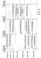
FIG. 7 is a flow diagram illustrating operations of the BS for the ARQ in the multihop relay wireless communication system according to an embodiment of the present invention. While the BS of the upper nodes is explained by way of example, the upper nodes operate the same as inFIG. 7 . - In
step 701, the BS determines whether to allocate the control channel for the ACK/NACK control message to the next-hop RS on the node basis as shown inFIG. 3A orFIG. 5A . - To allocate the control channel on the node basis, the BS confirms the unique IDs of the nodes that send the ACK/NACK message to the BS through the next-hop RS in
step 703. Herein, the unique ID indicates the CID. - In
step 705, the BS allocates the control channel for the ACK/NACK message based on the unique ID. - In
step 707, the BS generates the multi-control channel including the control channel information allocated for each unique ID. For example, the BS generates the IE including the control channel information allocated for each unique ID. - In
step 709, the BS transmits the multi-control channel to the next-hop RS. More specifically, the BS constitutes the UL-MAP, which includes the IE including the control channel information allocated for each unique ID, and transmits the UL-MAP to the next-hop RS. For example, the BS transmits the control channel information allocated for each unique ID to the next-hop RS as shown inFIG. 3A or5A . - By contrast, when determining not to allocate the control channel on the node basis in
step 701, the BS determines the nodes from which the ACK/NACK messages are received through the next-hop RS in each frame instep 711. - In
step 713, the BS transmits the information of the determined nodes to the next-hop RS. For instance, the BS transmits the information of the determined nodes to the next-hop RS using the broadcasting information or the separate control channel. - In
step 715, the BS allocates the multi-control channel to the next-hop RS to receive the ACK/NACK message with respect to the determined nodes. - Next, the BS proceeds to step 709 and transmits the multi-control channel to the next-hop RS. For example, the BS provides the multi-control channel information to the next-hop RS as shown in
FIG. 3B or5B . In doing so, the BS includes only the information of the start point and the end point of the multi-control channel. Thus, the RS, receiving the multi-control channel allocated from the BS, transmits the ACK/NACK messages of the nodes that are agreed with the BS instep 713, to the BS in the multi-control channel. - Next, the BS finishes this process.
- The structure of the RS for sending the ACK/NACK message for the retransmission in the wireless communication system is now explained.
-
FIG. 8 is a block diagram of the RS in the multihop relay wireless communication system according to an embodiment of the present invention. While it is assumed that atransmitter 800 and areceiver 820 use different antennas, they may share one antenna. - The RS of
FIG. 8 includes thetransmitter 800 and thereceiver 820. The RS also includes anARQ controller 840, anARQ state part 850, anARQ timer 860, and achannel estimator 870 which are shared by thetransmitter 800 and thereceiver 820. - The
transmitter 800 includes adata generator 801, achannel encoder 803, aCRC generator 805, amodulator 807, an Inverse Fast Fourier Transform (IFFT)operator 809, and a Radio Frequency (RF)processor 811. - The
data generator 801 aggregates data stored to adata queue 813 and a control message generated at amessage generator 817 in a Service Data Unit (SDU)generator 815, and generates one data for the physical layer transmission. Herein, when the data received through thereceiver 820 is detected with no errors, themessage generator 817 generates an ACK control message. When the data has an error, themessage generator 817 generates a NACK message. In doing so, when themessage generator 817 has the ACK/NACK message received from the lower node, it generates the message to deliver the ACK/ANCK message of the data received at the RS together with the ACK/NACK message received from the lower node. - The
channel encoder 803 encodes the data output from thedata generator 801 at a corresponding modulation level (e.g., MCS level). TheCRC generator 805 generates and inserts a CRC code to the data output from thechannel encoder 803. - The
modulator 807 modulates the data output from theCRC generator 805 at the corresponding modulation level (e.g., MCS level). - The
IFFT operator 809 IFFT-processes and converts the frequency-domain data output from themodulator 807 to a time-domain signal. - The
RF processor 811 up-converts the baseband signal output from theIFFT operator 809 to an RF signal and outputs the RF signal to the upper node or the lower node via the antenna. - The
receiver 820 includes anRF processor 821, anFFT operator 823, ademodulator 825, aCRC remover 827, achannel decoder 829, and adata processor 831. - The
RF processor 821 down-coverts the RF signal received on the antenna from the upper node or the lower node to a baseband signal. - The
FFT operator 823 FFT-processes and converts the time-domain signal output from theRF processor 821 to a frequency-domain signal. - The
demodulator 825 demodulates the signal output from theFFT operator 823 at the corresponding modulation level. Thedemodulator 825 outputs the demodulated signal to theCRC remover 827 and thechannel estimator 870. - The
CRC remover 827 determines whether the signal has error or not by checking the CRC code of the signal output from thedemodulator 825. TheCRC remover 827 eliminates the CRC code from the signal output from thedemodulator 825. - The
channel decoder 829 decodes the error-free signal output from theCRC remover 827 at the corresponding modulation level. - An
SDU processor 835 of thedata processor 831 separates the data and the control message from the physical layer signal output from thechannel decoder 829. Next, theSDU processor 835 provides and stores the data to asecond data queue 837, and provides and decodes the control message to amessage processor 833. Herein, thefirst data queue 813 and thesecond data queue 837 can be the same data queue. - The
message processor 833 confirms the ACK/NACK message received from the lower node. Themessage processor 833 confirms the multi-control channel information for the ACK/NACK message from the upper node, and provides the multi-control channel information to thetransmitter 800. - The
ARQ state part 850 manages the ARQ state for the retransmitted data. TheARQ timer 860 manages a lifetime for the retransmission of the RS. - The
ARQ controller 840 controls the ARQ operations of the RS in association with theARQ state part 850 and theARQ timer 860. TheARQ controller 840 controls the retransmission in communication with thedata generator 801, thechannel encoder 803, and theCRC generator 805 of thetransmitter 800. For example, when the retransmission request is received from the lower node through thereceiver 820, theARQ controller 840 controls thetransmitter 800 to send the retransmission request signal to the upper node. When the retransmission scheduling information is received from the upper node, theARQ controller 840 controls to encode the data received from the upper node and stored to thedata queue 813 according to the channel condition, to insert the CRC code, and to retransmit the data to the lower node which requests the retransmission. - The
ARQ controller 840 controls thetransmitter 800 to send the multi-ACK/NACK message. For example, theARQ controller 840 controls thetransmitter 800 to transmit the ACK/NACK message for the data received at the RS together with the ACK/NACK message from the lower node, to the upper node. - The
ARQ controller 840 controls the retransmission while communicating with thedata processor 831, thechannel decoder 829, and theCRC remover 827 of thereceiver 820. For instance, when theCRC remover 827 detects error in the received data, theARQ controller 840 controls themessage generator 817 to generate the NACK control message to be sent to the BS. - When receiving a lifetime expiration message from the
ARQ timer 860 in the process of the retransmission, theARQ controller 840 finishes the retransmission. - Now, another link configuration in the DL of the multihop relay wireless communication system is described. It is assumed that the fundamental unit of the data transmission in the wireless communication system is a frame. It is assumed that the frame is defined as a physical frame determined by taking into account the DL burst processing delay of the RS, the ACK feedback delay of the MS, and the ACK forwarding delay of the RS.
-
FIG. 9 illustrates a DL data transmission in a multihop relay wireless communication system according to another exemplary embodiment of the present invention. - The wireless communication system of
FIG. 9 includes aBS 900, afirst RS 902, afirst MS 904, asecond RS 906, and asecond MS 908. Herein, thefirst MS 904 represents at least one MS that communicates with thefirst RS 902, and thesecond MS 908 represents at least one MS that communicates with thesecond RS 906. - To transmit HARQ data to the
second MS 908, theBS 900 transmitsscheduling information 1 for sendingdata 1 to thesecond MS 908, anddata 1 to thefirst RS 902 over the i-th frame 910 instep 931. For example, the scheduling information is the HARQ DL-MAP information defined in the IEEE 802.16 standard. - Receiving the
scheduling information 1 anddata 1 from theBS 900, thefirst RS 902 forwards thescheduling information 1 anddata 1 to thesecond RS 906 over the (i+1)-th frame 912 instep 933. At this time, it is assumed thatdata 1 has no errors. - Upon receiving the
scheduling information 1 anddata 1 from thefirst RS 902, thesecond RS 906 forwards thescheduling information 1 anddata 1 to thesecond MS 908 over the (i+2)-th frame 914 instep 937. At this time, it is assumed thatdata 1 has no errors. - Upon receiving the
scheduling information 1 anddata 1 from thesecond RS 906, thesecond MS 908 confirms the ACK allocation region for sending an ACK/NACK message based on thescheduling information 1. - The
second MS 908 sends the ACK/NACK message fordata 1 to thesecond RS 906 through the ACK allocation region over the (i+3)-th frame 916 instep 941. - Upon receiving the ACK/NACK message for the
data 1 from thesecond MS 908, thesecond RS 906 forwards the ACK/NACK message of thesecond MS 908 fordata 1 to thefirst RS 902 over the (i+4)-th frame 918 instep 945. - Upon receiving the ACK/NACK message of the
second MS 908 fordata 1 from thesecond RS 906, thefirst RS 902 forwards the ACK/NACK message of thesecond MS 908 fordata 1 to theBS 900 over the (i+5)-th frame 906 instep 947. - Next, to transmit HARQ data to the
first MS 904, theBS 900 transmitsscheduling information 2 for sendingdata 2 to thefirst MS 904, anddata 2 to thefirst RS 902 over the (i+2)-th frame 914 instep 935. For example, the scheduling information is the HARQ DL-MAP information defined in the IEEE 802.16 standard. - Upon receiving the
scheduling information 2 anddata 2 from theBS 900, thefirst RS 902 forwards thescheduling information 2 anddata 2 to thefirst MS 904 over the (i+3)-th frame 916 instep 939. At this time, it is assumed thatdata 2 has no errors. - Receiving the
scheduling information 2 anddata 2 from thefirst RS 902, thefirst MS 904 confirms the ACK allocation region for sending the ACK/NACK message from thescheduling information 2. - Over the (i+4)-
th frame 918, thefirst MS 904 sends the ACK/NACK message fordata 2 to thefirst RS 902 through the ACK allocation region instep 943. - Receiving the ACK/NACK message for
data 2 from thefirst MS 904, thefirst RS 902 forwards the ACK/NACK message of thefirst MS 904 fordata 2 to theBS 900 over the (i+5)-th frame 920 instep 949. - As above, the
first RS 902 transmits the ACK/NACK message fordata 2 sent to thefirst MS 904 and the ACK/NACK message for thedata 1 sent to thesecond MS 908, to theBS 900 over the (i+5)-th frame 920. That is, the RS provides the multi-ACK/NACK message for the data received in the different time frames between the BS and the MS, to the upper node (e.g., the BS or the upper RS). - Thus, the upper node allocates the control channel for the multi-ACK/NACK message to the lower node so that the lower node can send the multi-ACK/NACK message as shown in
FIGs. 10A and 10B . InFIGs. 10A and 10B , the BS allocates the control channel for the multi-ACK/NACK message to the first RS, which is explained. -
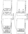
FIGs. 10A and 10B are diagrams illustrating frame structures for carrying ACK/NACK scheduling information for the DL data in the multihop relay wireless communication system according to an embodiment of the present invention. - As shown in
FIG. 10A or 10B , the BS allocates the multi-channel so that the first RS can send the ACK/NACK message for the DL data through the multi-channel. - In
FIG. 10A , the BS allocates different ACK allocation regions for the first MS and the second MS using the UL-MAP ofDL subframe 1000 and transmits the ACK allocation regions to the first RS. The BS constitutes resource allocation information sent to the first RS according to allocation information of the first MS and the second MS. - According to the resource allocation information from the BS, the first RS sends the ACK/
NACK message 1011 for the first MS and the ACK/NACK message 1013 for the second MS to the BS using the different regions ofUL subframe 1010 according to ACKregion scheduling information 1001, 1003. - In
FIG. 10B , the BS allocates the ACK allocation regions 1031 and the 1033 of the first MS and the second MS inUL subframe 1030 as one UL frame region using the ACKregion scheduling information 1021 of UL-MAP ofDL subframe 1020 and sends the UL frame region to the first RS. In this case, the wireless communication system can reduce the overhead in the DL scheduling, compared toFIG. 10A . - To allocate the ACK allocation regions as shown in
FIG. 10B , the BS needs to send to the first RS the information for distinguishing the ACK information of the first MS and the second MS in the one ACK allocation region allocated in the region of the UL subframe. For example, the BS includes the end point information of the ACK/NACK message of the MS or the start point information of the ACK/NACK message of the next MS, to the scheduling information of the ACK allocation region. - Alternatively, the first RS sends the ACK/NACK messages of the MSs in the data transmission order agreed with the BS. For instance, the BS transmits the
data 1 over the i-th frame 910 and then transmits thedata 2 over the (i+2)-th frame 914 inFIG. 9 . Thus, the first RS firstly sends the ACK/NACK message of the second MS for thedata 1 firstly received from the BS, over the (i+5)-th frame 920. Next, the first RS transmits the ACK/NACK message of the second MS for thedata 2. - After sending the ACK/NACK message of the second MS for the
data 2, the first RS can send the ACK/NACK message of the first MS for thedata 1. - Even when the BS transmits the
data 1 and thedata 2 in the same DL subframe and the first RS sends the ACK/NACK messages for thedata 1 and thedata 2 in the same UL subframe, the first RS can transmit the ACK/NACK messages in sequence in the order of the data scheduled and received from the BS. - Accordingly, the BS merely needs to inform the first RS of the region information of the UL frame for allocating the ACK/NACK messages from the next-hop MSs.
- As described above, using the MAP control message that is the ACK region allocation IE of the IEEE 802.16 standard, the BS can transmit the region information for delivering the ACK/NACK message to the lower RS. In the MAP control message, the ID of the lower RS and the UL ACK allocation region information are represented by the OFDM subchannel and by the OFDM symbol.
- Using the method of
FIG. 10A , the BS includes the end point information or the start point information of the multi-ACK channel to the MAP control message. Using the method ofFIG. 10B , the BS can transmit the multi-ACK channel in the order agreed between the BS and the RS without including the additional information to the MAP control message. - As set forth above, the upper node of the multihop relay wireless communication system transmits the multi-control channel to the lower node for the control message for the data retransmission. Therefore, the RS can transmit the control messages for the ARQ provided from the lower nodes and the control messages for the ARQ of the RS, to the upper node at the same time.
- While the invention has been shown and described with reference to certain preferred embodiments thereof, it will be understood by those skilled in the art that various changes in form and details may be made therein without departing from the scope of the invention as defined by the appended claims.
Claims (32)
- A method for operating a relay station, RS, in a wireless relay communication system, the method comprising:receiving (263) data from an upper node;receiving (271), from a first lower node, first information comprising acknowledgement, ACK, or negative acknowledgement, NACK, for data received by the first lower node; andreceiving (273), from a second lower node via the first lower node, second information comprising ACK or NACK for data received by the second lower node;characterized bytransmitting (281, 283, 285), to the upper node, the first information through a first resource region (313) in a frame (310), the second information through a second resource region (315) in the frame (310), and third information comprising ACK or NACK for the data received by the RS through a third resource region (311) in the frame (310),wherein the first resource region (313), the second resource region (315) and the third resource region (311) are indicated by scheduling information (301, 303, 305) received from the upper node, andwherein the first resource region (313), the second resource region (315), and the third resource region (311) are identified by the RS from the scheduling information (301, 303, 305) based on an identifier of the first lower node, an identifier of the second lower node, and an identifier of the RS.
- The method of claim 1, wherein the upper node comprises a base station, BS (200), or an upper RS (202).
- The method of claim 1, wherein the first lower node comprises an RS (204) and the second lower node comprises a mobile station, MS (206), or a lower RS.
- The method of claim 1, wherein the first resource region (313) corresponds to the identifier of the first lower node (204) and the second resource region (315) corresponds to the identifier of the second lower node (206).
- The method of claim 1, wherein the transmitting of the first information, the second information, and the third information comprises:
sequentially allocating the first information, the second information, and the third information in response to a data reception of corresponding data to regions indicated by the scheduling information based on a transmission order of the corresponding data. - The method of claim 1, wherein the scheduling information comprises MAP information.
- The method of claim 1, further comprising:
generating the third information in response to a data reception of the data received from the upper node (200, 202) after checking for errors. - A method for operating a relay station, RS, in a wireless relay communication system, the method comprising:receiving (457), from a first lower node, first information comprising acknowledgement, ACK, or negative acknowledgement, NACK, for data received by the first lower node; andreceiving (457) data from a second lower node via the first lower node;characterized bytransmitting (461, 463), to an upper node, the first information through a first resource region (511) in a frame (510) and second information comprising ACK or NACK for the data received by the RS through a second resource region (513) in the frame (510),wherein the first resource region (511) and the second resource region (513) are indicated by scheduling information (501, 503) received from the upper node, andwherein the first resource region (511) and the second resource region (513) are identified by the RS from the scheduling information (501, 503) based on an identifier of the first lower node and an identifier of the RS.
- The method of claim 8, wherein the first lower node comprises an RS (404), and the second lower node comprises a lower RS or a mobile station, MS (406).
- The method of claim 8, wherein the upper node comprises a base station, BS (400), or an upper RS (402).
- The method of claim 8, wherein the first resource region (511) corresponds to the identifier of the first lower node and the second resource region (513) corresponds to the identifier of the RS.
- The method of claim 8, wherein the scheduling information comprises MAP information.
- The method of claim 8, further comprising:
generating the second information in response to a data reception of the data received from the second lower node (406) after checking for errors. - A method for operating an upper node in a wireless relay communication system, the method comprising:transmitting, to a relay station, RS, scheduling information (301, 303; 501, 503) indicating a first resource region (311; 511) in a frame (310; 510) and a second resource region (313; 513) in the frame (310; 510); andreceiving (281, 283; 461, 463), from the RS, first information through the first resource region (311; 511) and second information through the second resource region (313; 513),wherein the first information comprises acknowledgement, ACK, or negative acknowledgement, NACK, for data received by at least one lower node,wherein the second information comprises ACK or NACK for data received by the RS, andwherein the first resource region (311; 511) and the second resource region (313; 513) are identified by the RS from the scheduling information (301, 303; 501, 503) based on an identifier of the at least one lower node and an identifier of the RS.
- The method of claim 14, wherein the upper node comprises a base station, BS (200; 400), or an upper RS (202; 402).
- The method of claim 14, wherein the at least one lower node comprises a lower RS (204; 404) or a mobile station, MS (206; 406).
- The method of claim 14, further comprising:identifying the identifier of the at least one lower node and the identifier of the RS; andallocating the first resource region (311; 511) and the second resource region (313; 513) based on the identifier of the at least one lower node and the identifier of the RS.
- The method of claim 14, wherein the first resource region (311; 511) corresponds to the identifier of the at least one lower node and the second resource region (313; 513) corresponds to the identifier of the RS.
- The method of claim 17, wherein the allocating of the first resource region (311; 511) and the second resource region (313; 513) comprises:
determining start point information and end point information of at least one of the first resource region (311; 511) and the second resource region (313; 513). - A relay station, RS, in a wireless relay communication system, the RS comprising:at least one processor (840); anda transceiver (800, 820) configured to:receive (263) data from an upper node,receive (271), from a first lower node, first information comprising acknowledgement, ACK, or negative acknowledgement, NACK, for data received by the first lower node, andreceive (273), from a second lower node via the first lower node, second information comprises ACK or NACK for data received by the second lower node,characterized in thatthe transceiver (800, 820) is further configured to transmit (281, 283, 285), to the upper node, the first information through a first resource region (313) in a frame (310), second information through a second resource region (315) in the frame (310), and third information comprising ACK or NACK for the data received by the RS through a third resource region (311) in the frame (310),wherein the first resource region (313), the second resource region (315), and the third resource region (311) are indicated by scheduling information (301, 303, 305) received from the upper node, andwherein the first resource region (313), the second resource region (315), and the third resource region (311) are identified by the RS from the scheduling information (301, 303, 305) based on an identifier of the first lower node, an identifier of the second lower node, and an identifier of the RS.
- The RS of claim 20, wherein the upper node comprises a base station, BS (200), or an upper RS (202).
- The RS of claim 20, wherein the first lower node comprises a RS (204), and the second lower node comprises a lower RS or a mobile station, MS (206).
- The RS of claim 20, wherein the first resource region (313) corresponds to the identifier of the first lower node (204), the second resource region (315) corresponds to an identifier of the second lower node (206), and the third resource region (311) corresponds to the identifier of the RS.
- The RS of claim 20, wherein the at least one processor (840) is further configured to:
sequentially allocate the first information, the second information, and the third information in response to a data reception of corresponding data to regions indicated by the scheduling information based on a transmission order of the corresponding data. - The RS of claim 20, wherein the scheduling information comprises MAP information.
- The RS of claim 20, wherein the at least one processor (840) is further configured to:
generate the third information in response to a data reception of the data received from the upper node (200, 202) after checking for errors. - A relay station, RS, in a wireless relay communication system, the RS comprising:at least one processor (840); anda transceiver (800, 820) configured to:receive (457), from a first lower node, first information comprising acknowledgement, ACK, or negative acknowledgement, NACK, for data received by the first lower node; andreceive (457) data from a second lower node via the first lower node,characterized in thatthe transceiver (800, 820) is further configured to transmit (461, 463), to an upper node, the first information through a first resource region (511) in a frame (510) and second information comprising ACK or NACK for the data received by the RS through a second resource region (513) in the frame (510),wherein the first resource region (511) and the second resource region (513) are indicated by scheduling information (510, 503) received from the upper node, andwherein the first resource region (511) and the second resource region (513) are identified by the RS from the scheduling information (501, 503) based on an identifier of the first lower node and an identifier of the RS.
- The RS of claim 27, wherein the first lower node comprises an RS (404) and the second lower node comprises a lower RS or a mobile station, MS (406).
- The RS of claim 27, wherein the upper node comprises a base station, BS (400), or an upper RS (402).
- The RS of claim 27, wherein the first resource region (511) corresponds to the identifier of the first lower node (404) and the second resource region (513) corresponds to the identifier of the RS.
- The RS of claim 27, wherein the scheduling information comprises MAP information.
- The RS of claim 27, wherein the at least one processor (840) is further configured to:
generate the second information in response to a data reception of the data received from the second lower node (406) after checking for errors.
Applications Claiming Priority (2)
| Application Number | Priority Date | Filing Date | Title |
|---|---|---|---|
| KR20070032983 | 2007-04-03 | ||
| KR1020070091258A KR101408940B1 (en) | 2007-04-03 | 2007-09-08 | Apparatus and method for data retrnasmission in wireless communication system using multi hop pelay |
Publications (3)
| Publication Number | Publication Date |
|---|---|
| EP2015498A2 EP2015498A2 (en) | 2009-01-14 |
| EP2015498A3 EP2015498A3 (en) | 2014-01-22 |
| EP2015498B1 true EP2015498B1 (en) | 2021-03-10 |
Family
ID=39434345
Family Applications (1)
| Application Number | Title | Priority Date | Filing Date |
|---|---|---|---|
| EP08006819.0A Ceased EP2015498B1 (en) | 2007-04-03 | 2008-04-03 | Relaystations and methods for data retransmission in multihop relay wireless communication system |
Country Status (3)
| Country | Link |
|---|---|
| US (1) | US8483116B2 (en) |
| EP (1) | EP2015498B1 (en) |
| WO (1) | WO2008120958A1 (en) |
Families Citing this family (30)
| Publication number | Priority date | Publication date | Assignee | Title |
|---|---|---|---|---|
| EP1976175B1 (en) * | 2007-03-30 | 2022-03-30 | Samsung Electronics Co., Ltd. | Apparatus and method for asynchronous control message transmission for data retransmission in wireless relay communication system |
| KR101572291B1 (en) | 2008-01-02 | 2015-12-02 | 인터디지탈 테크날러지 코포레이션 | Method and apparatus for cooperative wireless communications |
| US8301956B2 (en) * | 2008-04-07 | 2012-10-30 | Samsung Electronics Co., Ltd. | Methods and apparatus to improve communication in a relay channel |
| US8634763B2 (en) * | 2008-04-22 | 2014-01-21 | Intel Corporation | Cooperative communications techniques |
| JPWO2009150853A1 (en) * | 2008-06-13 | 2011-11-10 | パナソニック株式会社 | Relay station apparatus, radio communication apparatus, buffer clear method, and signal relay method |
| WO2010005951A2 (en) * | 2008-07-07 | 2010-01-14 | Interdigital Patent Holdings, Inc. | Method and apparatus for cooperative relaying in wireless communications |
| CN102119496B (en) * | 2008-10-31 | 2013-08-14 | 上海贝尔股份有限公司 | Distributed retransmission method based on superposition coded modulation in multihop relay network |
| KR101457708B1 (en) * | 2008-11-03 | 2014-11-04 | 엘지전자 주식회사 | Method for transmitting acknowledgement/non-acknowledgement in wireless communication systme comprising relay |
| KR101584814B1 (en) * | 2008-12-23 | 2016-01-13 | 엘지전자 주식회사 | Method and apparatus for transmitting scheduling request in wireless communication system |
| KR101607333B1 (en) * | 2009-03-05 | 2016-03-30 | 엘지전자 주식회사 | Method and apparatus for trnasmitting control signal of relay station |
| CN104660382B (en) * | 2009-03-11 | 2019-02-19 | 三星电子株式会社 | The transmission of confirmation signal in communication system |
| KR101729134B1 (en) * | 2009-03-27 | 2017-04-25 | 삼성전자주식회사 | Apparatus and method for arq feedback polling in wireless communication system |
| US8289895B2 (en) * | 2009-04-24 | 2012-10-16 | Research In Motion Limited | Relay link HARQ operation |
| CN101925110B (en) * | 2009-06-16 | 2013-08-07 | 中兴通讯股份有限公司 | Method, relay station and base station for transmitting uplink feedback information of relay link |
| WO2011014019A2 (en) * | 2009-07-29 | 2011-02-03 | 엘지전자 주식회사 | Method and apparatus for transmitting control signal of relay station in wireless communication system |
| EP2564658B1 (en) * | 2010-04-26 | 2015-03-11 | Nokia Solutions and Networks Oy | Connection arrangement in relayed wireless communications |
| KR101782928B1 (en) | 2010-04-29 | 2017-10-23 | 엘지전자 주식회사 | A method for transmitting ACK/NACK signal, and a base station and a user equipment thereof |
| KR101465909B1 (en) * | 2010-07-23 | 2014-11-26 | 엘지전자 주식회사 | Method and apparatus for transceiving control information and/or data to/from a base station via an anchor terminal in a wireless access system supporting machine-type communication |
| US9137642B2 (en) * | 2013-03-20 | 2015-09-15 | Google Inc. | Multi-cast optimized medium access method for wireless network |
| US9648514B2 (en) | 2013-08-09 | 2017-05-09 | Blackberry Limited | Method and system for protocol layer enhancements in data offload over small cells |
| KR20150130628A (en) * | 2014-05-13 | 2015-11-24 | 한국전자통신연구원 | Method for transmitting packet in low power wireless network |
| WO2016018383A1 (en) | 2014-07-31 | 2016-02-04 | Hewlett-Packard Development Company | Live migration of data |
| WO2016036347A1 (en) | 2014-09-02 | 2016-03-10 | Hewlett Packard Enterprise Development Lp | Serializing access to fault tolerant memory |
| US10594442B2 (en) * | 2014-10-24 | 2020-03-17 | Hewlett Packard Enterprise Development Lp | End-to-end negative acknowledgment |
| US10402287B2 (en) | 2015-01-30 | 2019-09-03 | Hewlett Packard Enterprise Development Lp | Preventing data corruption and single point of failure in a fault-tolerant memory |
| WO2016122642A1 (en) | 2015-01-30 | 2016-08-04 | Hewlett Packard Enterprise Development Lp | Determine failed components in fault-tolerant memory |
| US10409681B2 (en) | 2015-01-30 | 2019-09-10 | Hewlett Packard Enterprise Development Lp | Non-idempotent primitives in fault-tolerant memory |
| US10402261B2 (en) | 2015-03-31 | 2019-09-03 | Hewlett Packard Enterprise Development Lp | Preventing data corruption and single point of failure in fault-tolerant memory fabrics |
| US10389342B2 (en) | 2017-06-28 | 2019-08-20 | Hewlett Packard Enterprise Development Lp | Comparator |
| CN112205057B (en) * | 2018-05-16 | 2022-06-07 | 华为技术有限公司 | Data transmission method and device |
Family Cites Families (13)
| Publication number | Priority date | Publication date | Assignee | Title |
|---|---|---|---|---|
| US6990098B1 (en) * | 2000-09-11 | 2006-01-24 | Sun Microsystems, Inc. | Reliable multicast using merged acknowledgements |
| KR100876765B1 (en) * | 2002-05-10 | 2009-01-07 | 삼성전자주식회사 | Apparatus for retransmitting data in mobile communication system and method thereof |
| WO2004002082A1 (en) * | 2002-06-21 | 2003-12-31 | Siemens Aktiengesellschaft | Method and communication station for transmitting data |
| US7839858B2 (en) * | 2004-08-31 | 2010-11-23 | Telefonaktiebolaget Lm Ericsson | Data unit sender and data unit relay device |
| GB2417862B (en) * | 2004-09-01 | 2009-09-09 | Samsung Electronics Co Ltd | Adaptive ARQ system |
| WO2006071049A1 (en) | 2004-12-27 | 2006-07-06 | Lg Electronics Inc. | Supporting hybrid automatic retransmission request in orthogonal frequency division multiplexing access radio access system |
| JP2006196985A (en) | 2005-01-11 | 2006-07-27 | Kddi Corp | Media access control method of radio system and media access control program of repeater station |
| JP4637898B2 (en) | 2005-02-22 | 2011-02-23 | パナソニック株式会社 | Wireless communication method, relay station device, and wireless reception device |
| CN1941734A (en) | 2005-09-26 | 2007-04-04 | 华为技术有限公司 | Method and system for controlling fault based on transfer station |
| US8155016B2 (en) * | 2005-11-12 | 2012-04-10 | Rockstar Bidco, LP | System and method for unbalanced relay-based wireless communications |
| EP1801995A1 (en) * | 2005-12-21 | 2007-06-27 | Fujitsu Limited | Signalling in multi-hop communication systems |
| KR20060098413A (en) | 2006-08-28 | 2006-09-18 | (주) 평창정공 | A heating cylinder device of polishing machine for file |
| CN101166055B (en) | 2006-10-18 | 2011-06-01 | 华为技术有限公司 | Multi-hop relay method and multi-hop relay system |
-
2008
- 2008-04-03 US US12/062,137 patent/US8483116B2/en active Active
- 2008-04-03 WO PCT/KR2008/001884 patent/WO2008120958A1/en active Application Filing
- 2008-04-03 EP EP08006819.0A patent/EP2015498B1/en not_active Ceased
Non-Patent Citations (1)
| Title |
|---|
| None * |
Also Published As
| Publication number | Publication date |
|---|---|
| US20080248793A1 (en) | 2008-10-09 |
| EP2015498A2 (en) | 2009-01-14 |
| US8483116B2 (en) | 2013-07-09 |
| WO2008120958A1 (en) | 2008-10-09 |
| EP2015498A3 (en) | 2014-01-22 |
Similar Documents
| Publication | Publication Date | Title |
|---|---|---|
| EP2015498B1 (en) | Relaystations and methods for data retransmission in multihop relay wireless communication system | |
| US8462690B2 (en) | Apparatus and method for asynchronous control message transmission for data retransmission in wireless relay communication system | |
| US8201044B2 (en) | Apparatus and method for transmitting control message in a wireless communication system using relaying | |
| US8533552B2 (en) | Apparatus and method for retransmitting request in wireless relay communication system | |
| EP2088814B1 (en) | Radio relay station and radio terminal | |
| US8332704B2 (en) | Apparatus and method for supporting automatic retransmission request (ARQ) in a wireless relay communication system | |
| US8514822B2 (en) | Efficient acknowledgement messaging in wireless communications | |
| KR101075777B1 (en) | System and method for transmitting and receiving resource allocation information in a wireless communication system | |
| US8284754B2 (en) | Apparatus and method for determining time to response of retransmission in a multihop relay wireless communication system | |
| JP2008118499A (en) | Wireless base station, relay station, relay method | |
| EP1982455A2 (en) | A bandwidth efficient harq scheme in relay network | |
| US8248987B2 (en) | Apparatus and method for ACK channel transmission in wireless relay communication system | |
| KR20080079567A (en) | Apparatus and method for control message transmission in wireless communication system using relay | |
| CN102237989A (en) | Data transmission method and system | |
| US20110007684A1 (en) | Method for relaying and forwarding the feedback information in harq scenario | |
| AU2008219947B2 (en) | Apparatus and method for retransmitting request in wireless relay communication system | |
| JP5643852B2 (en) | Data retransmission apparatus and method in wireless communication system using multi-hop relay system | |
| EP2412122B1 (en) | Apparatus and method for arq feedback polling in wireless communication system | |
| KR20080089118A (en) | Apparatus and method for data retrnasmission of asynchronous control message transmission in wireless communication system using relay | |
| JP5304852B2 (en) | Radio base station, relay station, radio communication system, control method, relay method |
Legal Events
| Date | Code | Title | Description |
|---|---|---|---|
| PUAI | Public reference made under article 153(3) epc to a published international application that has entered the european phase |
Free format text: ORIGINAL CODE: 0009012 |
|
| 17P | Request for examination filed |
Effective date: 20080403 |
|
| AK | Designated contracting states |
Kind code of ref document: A2 Designated state(s): AT BE BG CH CY CZ DE DK EE ES FI FR GB GR HR HU IE IS IT LI LT LU LV MC MT NL NO PL PT RO SE SI SK TR |
|
| AX | Request for extension of the european patent |
Extension state: AL BA MK RS |
|
| RAP1 | Party data changed (applicant data changed or rights of an application transferred) |
Owner name: SAMSUNG ELECTRONICS CO., LTD. |
|
| RIC1 | Information provided on ipc code assigned before grant |
Ipc: H04L 1/16 20060101AFI20130813BHEP Ipc: H04L 5/00 20060101ALI20130813BHEP |
|
| PUAL | Search report despatched |
Free format text: ORIGINAL CODE: 0009013 |
|
| AK | Designated contracting states |
Kind code of ref document: A3 Designated state(s): AT BE BG CH CY CZ DE DK EE ES FI FR GB GR HR HU IE IS IT LI LT LU LV MC MT NL NO PL PT RO SE SI SK TR |
|
| AX | Request for extension of the european patent |
Extension state: AL BA MK RS |
|
| RIC1 | Information provided on ipc code assigned before grant |
Ipc: H04L 1/18 20060101ALI20131213BHEP Ipc: H04L 1/00 20060101ALI20131213BHEP Ipc: H04L 5/00 20060101ALI20131213BHEP Ipc: H04L 1/16 20060101AFI20131213BHEP |
|
| AKX | Designation fees paid |
Designated state(s): DE FR GB IT NL |
|
| STAA | Information on the status of an ep patent application or granted ep patent |
Free format text: STATUS: EXAMINATION IS IN PROGRESS |
|
| 17Q | First examination report despatched |
Effective date: 20180226 |
|
| GRAP | Despatch of communication of intention to grant a patent |
Free format text: ORIGINAL CODE: EPIDOSNIGR1 |
|
| STAA | Information on the status of an ep patent application or granted ep patent |
Free format text: STATUS: GRANT OF PATENT IS INTENDED |
|
| INTG | Intention to grant announced |
Effective date: 20201013 |
|
| GRAS | Grant fee paid |
Free format text: ORIGINAL CODE: EPIDOSNIGR3 |
|
| GRAA | (expected) grant |
Free format text: ORIGINAL CODE: 0009210 |
|
| STAA | Information on the status of an ep patent application or granted ep patent |
Free format text: STATUS: THE PATENT HAS BEEN GRANTED |
|
| AK | Designated contracting states |
Kind code of ref document: B1 Designated state(s): DE FR GB IT NL |
|
| REG | Reference to a national code |
Ref country code: GB Ref legal event code: FG4D |
|
| REG | Reference to a national code |
Ref country code: DE Ref legal event code: R096 Ref document number: 602008063760 Country of ref document: DE |
|
| REG | Reference to a national code |
Ref country code: NL Ref legal event code: FP |
|
| REG | Reference to a national code |
Ref country code: DE Ref legal event code: R097 Ref document number: 602008063760 Country of ref document: DE |
|
| PLBE | No opposition filed within time limit |
Free format text: ORIGINAL CODE: 0009261 |
|
| STAA | Information on the status of an ep patent application or granted ep patent |
Free format text: STATUS: NO OPPOSITION FILED WITHIN TIME LIMIT |
|
| 26N | No opposition filed |
Effective date: 20211213 |
|
| PG25 | Lapsed in a contracting state [announced via postgrant information from national office to epo] |
Ref country code: IT Free format text: LAPSE BECAUSE OF FAILURE TO SUBMIT A TRANSLATION OF THE DESCRIPTION OR TO PAY THE FEE WITHIN THE PRESCRIBED TIME-LIMIT Effective date: 20210310 |
|
| PGFP | Annual fee paid to national office [announced via postgrant information from national office to epo] |
Ref country code: GB Payment date: 20220321 Year of fee payment: 15 |
|
| PG25 | Lapsed in a contracting state [announced via postgrant information from national office to epo] |
Ref country code: FR Free format text: LAPSE BECAUSE OF NON-PAYMENT OF DUE FEES Effective date: 20210510 |
|
| PGFP | Annual fee paid to national office [announced via postgrant information from national office to epo] |
Ref country code: NL Payment date: 20220322 Year of fee payment: 15 |
|
| PGFP | Annual fee paid to national office [announced via postgrant information from national office to epo] |
Ref country code: DE Payment date: 20220321 Year of fee payment: 15 |
|
| REG | Reference to a national code |
Ref country code: DE Ref legal event code: R119 Ref document number: 602008063760 Country of ref document: DE |
|
| REG | Reference to a national code |
Ref country code: NL Ref legal event code: MM Effective date: 20230501 |
|
| GBPC | Gb: european patent ceased through non-payment of renewal fee |
Effective date: 20230403 |
|
| PG25 | Lapsed in a contracting state [announced via postgrant information from national office to epo] |
Ref country code: GB Free format text: LAPSE BECAUSE OF NON-PAYMENT OF DUE FEES Effective date: 20230403 |
|
| PG25 | Lapsed in a contracting state [announced via postgrant information from national office to epo] |
Ref country code: NL Free format text: LAPSE BECAUSE OF NON-PAYMENT OF DUE FEES Effective date: 20230501 Ref country code: GB Free format text: LAPSE BECAUSE OF NON-PAYMENT OF DUE FEES Effective date: 20230403 Ref country code: DE Free format text: LAPSE BECAUSE OF NON-PAYMENT OF DUE FEES Effective date: 20231103 |