EP2015381A2 - Cordless power tool system - Google Patents
Cordless power tool system Download PDFInfo
- Publication number
- EP2015381A2 EP2015381A2 EP08157843A EP08157843A EP2015381A2 EP 2015381 A2 EP2015381 A2 EP 2015381A2 EP 08157843 A EP08157843 A EP 08157843A EP 08157843 A EP08157843 A EP 08157843A EP 2015381 A2 EP2015381 A2 EP 2015381A2
- Authority
- EP
- European Patent Office
- Prior art keywords
- axis
- terminal
- battery pack
- housing
- battery
- Prior art date
- Legal status (The legal status is an assumption and is not a legal conclusion. Google has not performed a legal analysis and makes no representation as to the accuracy of the status listed.)
- Withdrawn
Links
Images

Classifications
-
- H—ELECTRICITY
- H01—ELECTRIC ELEMENTS
- H01M—PROCESSES OR MEANS, e.g. BATTERIES, FOR THE DIRECT CONVERSION OF CHEMICAL ENERGY INTO ELECTRICAL ENERGY
- H01M50/00—Constructional details or processes of manufacture of the non-active parts of electrochemical cells other than fuel cells, e.g. hybrid cells
- H01M50/20—Mountings; Secondary casings or frames; Racks, modules or packs; Suspension devices; Shock absorbers; Transport or carrying devices; Holders
- H01M50/204—Racks, modules or packs for multiple batteries or multiple cells
- H01M50/207—Racks, modules or packs for multiple batteries or multiple cells characterised by their shape
- H01M50/213—Racks, modules or packs for multiple batteries or multiple cells characterised by their shape adapted for cells having curved cross-section, e.g. round or elliptic
-
- B—PERFORMING OPERATIONS; TRANSPORTING
- B25—HAND TOOLS; PORTABLE POWER-DRIVEN TOOLS; MANIPULATORS
- B25F—COMBINATION OR MULTI-PURPOSE TOOLS NOT OTHERWISE PROVIDED FOR; DETAILS OR COMPONENTS OF PORTABLE POWER-DRIVEN TOOLS NOT PARTICULARLY RELATED TO THE OPERATIONS PERFORMED AND NOT OTHERWISE PROVIDED FOR
- B25F5/00—Details or components of portable power-driven tools not particularly related to the operations performed and not otherwise provided for
- B25F5/02—Construction of casings, bodies or handles
-
- H—ELECTRICITY
- H01—ELECTRIC ELEMENTS
- H01M—PROCESSES OR MEANS, e.g. BATTERIES, FOR THE DIRECT CONVERSION OF CHEMICAL ENERGY INTO ELECTRICAL ENERGY
- H01M10/00—Secondary cells; Manufacture thereof
- H01M10/42—Methods or arrangements for servicing or maintenance of secondary cells or secondary half-cells
- H01M10/46—Accumulators structurally combined with charging apparatus
-
- H—ELECTRICITY
- H01—ELECTRIC ELEMENTS
- H01M—PROCESSES OR MEANS, e.g. BATTERIES, FOR THE DIRECT CONVERSION OF CHEMICAL ENERGY INTO ELECTRICAL ENERGY
- H01M50/00—Constructional details or processes of manufacture of the non-active parts of electrochemical cells other than fuel cells, e.g. hybrid cells
- H01M50/20—Mountings; Secondary casings or frames; Racks, modules or packs; Suspension devices; Shock absorbers; Transport or carrying devices; Holders
- H01M50/204—Racks, modules or packs for multiple batteries or multiple cells
- H01M50/207—Racks, modules or packs for multiple batteries or multiple cells characterised by their shape
- H01M50/209—Racks, modules or packs for multiple batteries or multiple cells characterised by their shape adapted for prismatic or rectangular cells
-
- H—ELECTRICITY
- H01—ELECTRIC ELEMENTS
- H01M—PROCESSES OR MEANS, e.g. BATTERIES, FOR THE DIRECT CONVERSION OF CHEMICAL ENERGY INTO ELECTRICAL ENERGY
- H01M10/00—Secondary cells; Manufacture thereof
- H01M10/05—Accumulators with non-aqueous electrolyte
- H01M10/052—Li-accumulators
- H01M10/0525—Rocking-chair batteries, i.e. batteries with lithium insertion or intercalation in both electrodes; Lithium-ion batteries
-
- Y—GENERAL TAGGING OF NEW TECHNOLOGICAL DEVELOPMENTS; GENERAL TAGGING OF CROSS-SECTIONAL TECHNOLOGIES SPANNING OVER SEVERAL SECTIONS OF THE IPC; TECHNICAL SUBJECTS COVERED BY FORMER USPC CROSS-REFERENCE ART COLLECTIONS [XRACs] AND DIGESTS
- Y02—TECHNOLOGIES OR APPLICATIONS FOR MITIGATION OR ADAPTATION AGAINST CLIMATE CHANGE
- Y02E—REDUCTION OF GREENHOUSE GAS [GHG] EMISSIONS, RELATED TO ENERGY GENERATION, TRANSMISSION OR DISTRIBUTION
- Y02E60/00—Enabling technologies; Technologies with a potential or indirect contribution to GHG emissions mitigation
- Y02E60/10—Energy storage using batteries
Definitions
- the pack housing 20 can have a sidewall 42, which can extend along a longitudinal axis 44 of the pack housing 20, a first end wall 46, which can be coupled to a first end of the sidewall 42, and a second end wall 50 that can be coupled to the sidewall 42 on a side opposite the first end of the sidewall 42.
- the pack housing 20 can have a substantially ovoidal cylindrical shape with an exterior surface 52 having a cross-sectional shape that is symmetric about a major axis 54 and a minor axis 56.
- the pack housing 20 can have a cross-sectional shape with an exterior surface 52 that is shaped as a rounded rectangle.
- the battery assembly 22 can include a pair of battery cells 96 and a thermistor 98.
- the battery cells 96 can be coupled together in an appropriate manner (e.g., in series) and can have a desired battery chemistry, such as a lithiumion battery chemistry.
- the thermistor 98 can be disposed in close proximity to the battery cells 96 to thereby receive heat that is generated by the battery cells 96 when the battery pack 12 is being charged and/or discharged.
Landscapes
- Chemical & Material Sciences (AREA)
- Chemical Kinetics & Catalysis (AREA)
- Electrochemistry (AREA)
- General Chemical & Material Sciences (AREA)
- Engineering & Computer Science (AREA)
- Mechanical Engineering (AREA)
- Manufacturing & Machinery (AREA)
- Battery Mounting, Suspending (AREA)
Abstract
Description
- The present invention generally relates to a system of cordless tools and more particularly to a system of cordless tools having a battery pack that is well suited for use with tools having relatively large housings that include a handle, as well as for use with tools having relatively small housings where the battery pack is employed as a handle.
- Typical cordless tool systems employ a battery pack that can be removably coupled to a plurality of different tools. These tools typically include drills and saws that employ fairly substantial housings that include a handle that may be grasped by the hand of the user to manipulate and operate the tool. Moreover, the housings of such tools can be configured to prevent insertion of the battery pack in a wrong orientation.
- The inventors of the present invention have devised a modular cordless tool system in which one or more battery packs may be removably coupled to a tool having a substantial housing (i.e., a housing that includes a handle) as well as to a tool having an insubstantial housing (i.e., a housing without a handle). For this latter type of tool, the present inventors have found it desirable that the battery pack itself form the handle or base and that the battery pack can have an approximately ovoidal cylindrical shape that can fit comfortable into the hand of the user, despite the size of the user's hand or whether the user is left- or right-handed.
- As modern battery packs can employ several terminals (e.g., a positive terminal, a negative terminal, a thermistor terminal), it was desirable to provide a battery pack with a housing that was substantially symmetric about its longitudinal axis so that it could be employed as a comfortable ambidextrous handle but which would protect the terminals of the battery pack and/or the tool if the user attempted to insert the battery pack into the tool in the wrong orientation.
- In one form, the present invention provides a battery pack that includes a housing, at least one battery cell contained within the housing, a first terminal and a second terminal. The housing preferably includes a substantially ovoidal surface which is substantially symmetric about a first axis of symmetry and a second axis of symmetry which is transverse to the first axis. The surface preferably has first and second substantially linear terminal openings. Preferably, the first opening extends substantially parallel to and is non-coincident with the first axis, while the second opening preferably extends substantially parallel to the second axis. The first and second terminals preferably are disposed within the housing adjacent to the surface. The first terminal preferably is accessible through the first opening and the second terminal preferably is accessible through the second opening.
- Preferably, said first axis comprises a major axis and said second axis comprises a minor axis. Said second opening preferably extends non-coincidental to said minor axis. Said first axis preferably comprises a minor axis and said second axis preferably comprises a major axis. The ovoidal surface preferably comprises a rounded rectangle. Alternatively, the ovoidal surface preferably comprises an oval. Advantageously, said surface may have a lockout opening, wherein said lockout opening is not intersected by at least one of said first axis and said second axis. Said housing may extend in a longitudinal direction which is substantially perpendicular to said surface and may have an ovoidal cross-sectional shape for at least a portion of its dimension in the longitudinal direction. Said housing may extend in a longitudinal direction which is substantially perpendicular to said surface and may have an ovoidal cross-sectional shape for substantially its entire dimension in the longitudinal direction.
- In another form, the invention provides a battery pack that includes a housing, at least one battery cell contained with the housing, first and second terminal openings, first and second terminals and a lock-out opening. The housing preferably has a substantially ovoidal cross-section that extends in a longitudinal dimension, and preferably a substantially flat forward surface. The forward surface preferably is substantially symmetric about a first axis of symmetry and a second axis of symmetry that is transverse to the first axis. The first and second terminal openings preferably extend through the forward surface. The first terminal and a second terminal preferably are disposed within the housing adjacent to the surface. The first terminal preferably is accessible through the first opening and the second terminal preferably is accessible through the second opening. The lockout opening preferably extends through the surface. The lockout opening preferably does not intersect at least one of said first axis and said second axis. Said ovoidal cross-section may comprise a rounded rectangle. Alternatively, said ovoidal cross-section may comprise an oval. Said housing may include a raised collar disposed about said forward flat surface and having a corresponding shape. Said lockout opening preferably does not intersect both said first axis and said second axis.
- In still another form, the invention provides an electrical device for use with a battery pack having a housing with a forward surface having a substantially ovoidal cross-section which is substantially symmetric about a first axis of symmetry and a second axis of symmetry, first and second terminal openings extending through the forward surface and a first terminal and a second terminal disposed within the housing and accessible through the first and second openings, respectively. The device preferably includes a pack receiving cavity and a pair of terminal blades. The pack-receiving cavity preferably has a substantially ovoidal cross-section that substantially corresponds to the forward surface of the pack with a first axis of symmetry and a second axis of symmetry. The terminal blades preferably are disposed in the cavity such that the first blade extends substantially parallel to and non-coincidental with the first axis and the second blade parallel to the second axis. Said first axis may comprise a major axis and said second axis may comprise a minor axis, said second blade extending non-coincidental to said minor axis. Said first axis may comprise a minor axis and said second axis may comprise a major axis, said second blade extending non-coincidental to said major axis. Said device may be a battery charger or a power tool, for example. Said ovoidal cross-section may comprise a rounded rectangle. Alternatively, said ovoidal cross-section may comprise an oval.
- In yet another form, the invention provides an electrical device for use with a battery pack having a housing with a forward surface having a substantially ovoidal cross-section which is substantially symmetric about a first axis of symmetry and a second axis of symmetry, first and second terminal openings extending through the forward surface and a first terminal and a second terminal disposed within the housing and accessible through the first and second openings, respectively, and a lock out opening disposed through the surface. The device preferably comprises a pack receiving cavity, a pair of terminal blades and a lock-out projection. The pack-receiving cavity preferably has a substantially ovoidal cross-section substantially corresponding to the forward surface of the pack with a first axis of symmetry and a second axis of symmetry. The pack-receiving cavity preferably extends in a longitudinal direction. The terminal blades preferably are disposed in the cavity and extend along the longitudinal direction. The lockout projection preferably extends along the longitudinal direction for a distance greater than the extent of the blades. Preferably, at least one of the first axis and the second axis does not intersect the lockout projection. Said ovoidal cross-section may comprise a rounded rectangle. Alternatively, said ovoidal cross-section may comprise an oval. Advantageously, both said first axis and said second axis do not intersect said lockout projection. Said device may be a battery charger or a power tool, for example.
- It is to be understood that any feature of any aspect of the invention may be a feature of any other aspect of the invention.
- Further areas of applicability will become apparent from the description provided herein. It should be understood that the description and specific examples are intended for purposes of illustration only and are not intended to limit the scope of the present disclosure.
- The invention will now be described, by way of example, with reference to the accompanying drawings.
-
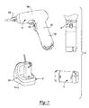
Figure 1 is a perspective view of a system of cordless tools constructed in accordance with the teachings of the present disclosure; -
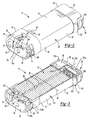
Figure 2 is a perspective view of a portion of the system of cordless power tools ofFigure 1 , illustrating the battery pack in more detail; -
Figure 3 is a longitudinal sectional view of the battery pack; -
Figure 4 is an end view of battery pack; -
Figure 5 is partially broken-away perspective view of a portion of the system of cordless tools ofFigure 1 , illustrating a portion of the first tool in more detail; -
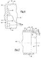
Figure 6 is a section view of a portion of the first tool, illustrating the a first end of a battery connection portion; -
Figure 7 is a section view of a portion of the first tool, illustrating an opposite end of the battery connection portion with the battery pack coupled thereto; -
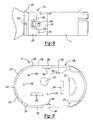
Figure 8 is a side elevation view of a portion of the system of cordless tools ofFigure 1 , illustrating the battery pack as coupled to a second tool; and -
Figure 9 is a bottom plan view of the second tool. - With reference to
Figure 1 of the drawings, a system of cordless power tools constructed in accordance with the teachings of the present invention is generally indicated byreference numeral 10. Thesystem 10 can include abattery pack 12, afirst tool 14, asecond tool 16, and abattery charger 18. - With reference to
Figures 2 and 3 , thebattery pack 12 can include apack housing 20, abattery assembly 22, a set ofbattery terminals 24 and alatch 26. Thepack housing 20 can include abody member 30 and first and second end caps 32 and 34, respectively, that can be coupled together to enclose thebattery assembly 22. The first and second end caps 32 and 34 can be coupled to thebody member 30 in any convenient manner, such astabs 38 that can be formed on thebody member 30 andresilient hooks 40 that can be formed on the first and second end caps 32 and 34. It will be appreciated that thepack housing 20 could be configured differently, such as via a pair of clam shell half members (not shown) that are coupled to one another. - The
pack housing 20 can have asidewall 42, which can extend along a longitudinal axis 44 of thepack housing 20, afirst end wall 46, which can be coupled to a first end of thesidewall 42, and asecond end wall 50 that can be coupled to thesidewall 42 on a side opposite the first end of thesidewall 42. Thepack housing 20 can have a substantially ovoidal cylindrical shape with anexterior surface 52 having a cross-sectional shape that is symmetric about amajor axis 54 and aminor axis 56. For example, thepack housing 20 can have a cross-sectional shape with anexterior surface 52 that is shaped as a rounded rectangle. With additional reference toFigure 4 , thefirst end wall 46 can be generally perpendicular to the longitudinal axis 44 of thepack housing 20 and can define a substantiallyovoidal surface 60 with a firstterminal opening 62 and a secondterminal opening 64. The first and secondterminal openings first end wall 46 that are disposed inwardly of (and do not intersect) the exterior perimeter of the substantiallyovoidal surface 60. The first terminal opening 62 can be generally parallel to and spaced apart from themajor axis 54, while the second terminal opening 64 can be generally parallel to theminor axis 56. In the particular example provided, the first and secondterminal openings major axis 54. - The
first end cap 32 can include one or more one or more lock-out features 70, one or more clipping features 72 and a plurality ofspring terminal openings 74. The lock-out feature(s) 70 can comprise a projection or depression of any desired shape, such as acylindrical depression 76, asemi-cylindrical depression 78 and/or one ormore notches 80 that are formed into thefirst end cap 32 parallel to the longitudinal axis 44 of thebattery pack 12. The clipping features 72 can comprise one ormore recesses 84 that can be formed in thesidewall 42 and can define a ledge 86. Thespring terminal openings 74 can be located in any convenient location. In the particular example provided, thespring terminal openings 74 comprise a plurality ofgrooves 88 that are formed into thesidewall 42 symmetrically about themajor axis 54. - With renewed reference to
Figures 2 and 3 , thesecond end cap 34 can be coupled to thebody member 30 in a manner that is similar to the manner in which thefirst end cap 32 is coupled to thebody member 30. Thesecond end cap 34 can define alatch actuator recess 92. Thelatch actuator recess 92 can be formed in an end of thepack housing 20 opposite the substantiallyovoidal surface 60. - With reference to
Figure 3 , the construction of thebattery assembly 22 is beyond the scope of the present disclosure and need not be described in significant detail herein. Briefly, thebattery assembly 22 can include a pair ofbattery cells 96 and athermistor 98. Thebattery cells 96 can be coupled together in an appropriate manner (e.g., in series) and can have a desired battery chemistry, such as a lithiumion battery chemistry. Thethermistor 98 can be disposed in close proximity to thebattery cells 96 to thereby receive heat that is generated by thebattery cells 96 when thebattery pack 12 is being charged and/or discharged. - With reference to
Figures 2 through 4 , the set ofbattery terminals 24 can include afirst pack terminal 100, asecond pack terminal 102 and a plurality ofthird pack terminals 104. In the particular example provided, the first andsecond pack terminals third pack terminals 104 are cantilevered leaf spring-type terminals that are configured to abut a corresponding terminal in the battery charger 18 (Fig. 1 ), for example. In the particular example provided, thefirst pack terminal 100 is electrically coupled to the negative terminal (not shown) of thebattery assembly 22, thesecond pack terminal 102 is electrically coupled to the positive terminal (not shown), a first one 104a of thethird pack terminals 104 is electrically coupled to thethermistor 98, a second one 104b of thethird pack terminals 104 is electrically coupled to a device that identifies the battery pack 12 (e.g., an identification integrated circuit, resistor and/or diode), and a third one 104c of thethird pack terminals 104 is electrically coupled to one of thebattery cells 96 to provide an inter-cell voltage tap. The first andsecond pack terminals terminal openings third pack terminals 104 are received into thespring terminal openings 74. Thepack housing 20 can be employed to fix the first, second andthird pack terminals pack housing 20 can be configured such that the first andsecond pack terminals terminal openings - With specific reference to
Figure 3 , thelatch 26 can have alatch body 120 and atang 122 that can extend outwardly from thelatch body 120. A stop member 124 can be formed on thelatch body 120. Thetang 122 can include a tapered leadingsurface 128 and anabutting edge 130. Thelatch 26 can be received in thelatch actuator recess 92 such that thetang 122 is positioned to extend outwardly from thesidewall 42 of thepack housing 20. A spring 134 can be employed to bias the latch member outwardly from thelatch actuator recess 92. The stop member 124 can contact thebody member 30 of thepack housing 20 to limit outward movement of thelatch 26. Agrip portion 138 can be coupled to thelatch body 120 to provide a comfortable means for selectively moving thetang 122. - With renewed reference to
Figure 1 , thefirst tool 14 can be any type of tool having a relativelysubstantial housing 150 with ahandle 152. For example, thefirst tool 14 can be a screwdriver with a motor andtransmission assembly 154, anoutput member 156 that can be driven by the motor andtransmission assembly 154, and abattery connection portion 158. - With reference to
Figures 5 and6 , thebattery connection portion 158 can include ahousing member 160, aterminal block 162 and a plurality of mating lock-out features 164. Thehousing member 160 can include awall member 170 that can be integrally formed with thehousing 150. In the example provided, thewall member 170 defines a portion of thehandle 152, as well as abattery chamber 172 with anovoidal opening 174 that is configured to receive thebattery pack 12 therein. Theterminal block 162 can include ablock member 176 and first andsecond tool terminals block member 176. The first andsecond tool terminals battery chamber 172 by a first distance. The first andsecond tool terminals terminal openings 62 and 64 (Fig. 4 ), respectively, and electrically engage the first andsecond pack terminals 100 and 102 (Fig. 4 ), respectively, when thebattery pack 12 is fully received into thebattery chamber 172. - In the particular example provided, the mating lock-out
features 164 comprise afirst projection 190 that is configured to be received in the cylindrical depression 76 (Fig. 4 ) and asecond projection 192 that is configured to be received in the semi-cylindrical depression 78 (Fig. 4 ). The first andsecond projections battery chamber 172 by a second distance that is greater than the first distance. Accordingly, if thebattery pack 12 were to be fitted into thebattery chamber 172 in the wrong orientation, contact between the mating lock-outfeatures 164 and the pack housing 20 (Fig. 4 ) inhibits contact between the first andsecond tool terminals pack housing 20. - With reference to
Figure 7 , contact between the tapered leadingsurface 128 of thetang 122 and thehousing member 160 as thebattery pack 12 is inserted into thebattery chamber 172 along aninsertion axis 200 pushes thetang 122 inwardly toward theinsertion axis 200 to permit thetang 122 to pass through theexterior surface 202 of thehousing member 160. Alignment of thetang 122 to atang recess 204 in thehousing member 160 after the first andsecond tool terminals 178 and 180 (Fig. 5 ) have been matingly engaged to the first andsecond pack terminals 100 and 102 (Fig. 4 ), respectively, permits thetang 122 to move outwardly from thepack housing 20 due to the spring 134 (Fig. 3 ) so that theabutting edge 130 of thetang 122 abuts acorresponding edge 206 of thetang recess 204. Thegrip portion 138 of thelatch body 120 may be moved in a direction that is parallel to a plane that extends longitudinally through thebattery pack 12 that includes themajor axis 54 and theinsertion axis 200 and which is perpendicular to theminor axis 56 to retract thetang 122 toward thesidewall 42 to thereby disengage thetang 122 from thehousing member 160 so that thebattery pack 12 may be withdrawn from thebattery chamber 172. To further facilitate withdrawal of thebattery pack 12, thehousing member 160 can be recessed at a first location 210 (Fig. 5 ), which corresponds to the location of thegrip portion 138 when thebattery pack 12 is inserted into thebattery chamber 172, and a second location 212 (Fig. 5 ) that can be disposed opposite thefirst location 210. Thehousing member 160 may otherwise shroud thebattery pack 12. For example, thehousing member 160 may include wing portions 214 (Fig. 5 ) that extend to or beyond the second end of thebattery pack 12 when thebattery pack 12 is fully installed to thehousing member 160. - With reference to
Figure 8 , thesecond tool 16 can be any type of tool having a relativelyinsubstantial housing 230 that does not include a handle. For example, thesecond tool 16 can be a flash light having alight source 232, aswitch 234 and abattery connection portion 238. - In
Figure 9 , thebattery connection portion 238 can include ahousing member 240, aterminal block 242, a plurality of mating lock-outfeatures 244 and a pair oflatch members 246 that can be movably coupled toopposite sides 248 of thehousing member 240. Thehousing member 240 can include awall member 250 that can define abattery recess 252 with anopening 254 that is configured to receive thebattery pack 12 therein (Fig. 8 ). Theterminal block 242 can include ablock member 260 and first andsecond tool terminals block member 260. The first andsecond tool terminals battery recess 252 by the first distance (similar to the configuration of thefirst tool 14 described above). The first andsecond tool terminals terminal openings 62 and 64 (Fig. 4 ), respectively, and electrically engage the first andsecond pack terminals 100 and 102 (Fig. 4 ), respectively, when thebattery pack 12 is received into thebattery recess 252. In the particular example provided, the mating lock-outfeatures 244 comprise afirst projection 270, which is configured to be received in the cylindrical depression 76 (Fig. 4 ), asecond projection 272, which is configured to be received in the semi-cylindrical depression 78 (Fig. 4 ), a set ofthird projections 274, which are configured to be received in the notches 80 (Fig. 4 ), and a set offourth projections 276 that are configured to be aligned to the spring terminal openings 74 (Fig. 4 ). The first andsecond projections battery recess 252 by a second distance that is greater than the first distance (similar to the configuration of the first tool described above). Thethird projections 274 andfourth projections 276 can be sized to require alignment between thesecond tool 16 and thebattery pack 12 before thebattery pack 12 is received into thebattery recess 252. Thelatch members 246 can include alatch tang 280 that can releasably engage the recesses 84 (Fig. 2 ) in the sidewall 42 (Fig. 2 ) to thereby couple thesecond tool 16 to the battery pack 12 (Fig. 8 ). - It will be appreciated that while the latching of the
second tool 16 to thebattery pack 12 is robust, it is nonetheless somewhat more delicate than the latching of thefirst tool 14 to thebattery pack 12. Accordingly, the asymmetric orientation of the first andsecond pack terminals 100 and 102 (Fig. 4 ) can help to stabilize the connection between thesecond tool 16 and the battery pack 12 (Fig. 8 ). For example, the orientation of the first pack terminal 100 (Fig. 4 ) can render the first pack terminal 100 (Fig. 4 ) somewhat more resistant to bending than the second pack terminal 102 (Fig. 4 ) in response to a load applied to thesecond tool 16 in a direction parallel to the major axis 54 (Fig. 3 ). Similarly, the orientation of the second pack terminal 102 (Fig. 4 ) can render the second pack terminal 102 (Fig. 4 ) somewhat more resistant to bending than the first pack terminal 100 (Fig. 4 ) in response to a load applied to thesecond tool 16 in a direction parallel to the minor axis 56 (Fig. 3 ). - Aside from the connection to the
battery pack 12, the battery charger 18 (Fig. 1 ) can be configured in a conventional manner and as such, the components of thebattery charger 18, such as its charging circuit, need not be discussed in detail herein. With reference toFigure 1 , thebattery charger 18 can include ahousing 300 that can have abattery connection portion 302 that can be similar to thebattery connection portion 158 of thefirst tool 14, except that thebattery connection portion 302 can include one or more auxiliary terminals (not shown) that can be electrically coupled to the spring terminals 104 (Fig. 4 ) when thebattery pack 12 is inserted into thebattery connection portion 302. - While specific examples have been described in the specification and illustrated in the drawings, it will be understood by those of ordinary skill in the art that various changes may be made and equivalents may be substituted for elements thereof without departing from the scope of the present disclosure as defined in the claims. Furthermore, the mixing and matching of features, elements and/or functions between various examples is expressly contemplated herein so that one of ordinary skill in the art would appreciate from this disclosure that features, elements and/or functions of one example may be incorporated into another example as appropriate, unless described otherwise, above. Moreover, many modifications may be made to adapt a particular situation or material to the teachings of the present disclosure without departing from the essential scope thereof. Therefore, it is intended that the present disclosure not be limited to the particular examples illustrated by the drawings and described in the specification as the best mode presently contemplated for carrying out this invention, but that the scope of the present disclosure will include any embodiments falling within the foregoing description and the appended claims.
Claims (12)
- A battery pack comprising:a housing including a substantially ovoidal surface which is substantially symmetric about a first axis of symmetry and a second axis of symmetry which is transverse to said first axis, said surface having first and second substantially linear terminal openings, said first opening extending substantially parallel to and non-coincidental with said first axis and said second opening extending substantially parallel to said second axis;at least one battery cell contained within said housing;a first terminal and a second terminal disposed within said housing adjacent to said surface, said first terminal accessible through first opening and said second terminal accessible through said second opening.
- A battery pack according to claim 1, said first axis comprising a major axis and said second axis comprising a minor axis.
- A pack according to claim 1 or claim 2, said second opening extending non-coincidental to said minor axis.
- A battery pack according to any preceding claim, said first axis comprising a minor axis and said second axis comprising a major axis.
- A battery pack according to any preceding claim, the ovoidal surface comprising a rounded rectangle.
- A battery pack according to any one of claims 1 to 4, the ovoidal surface comprising an oval.
- A battery pack according to any preceding claim, said surface having a lockout opening, wherein said lockout opening is not intersected by at least one of said first axis and said second axis.
- A battery pack according to any preceding claim, said housing extending in a longitudinal direction which is substantially perpendicular to said surface and having an ovoidal cross-sectional shape for at least a portion of its dimension in the longitudinal direction.
- A battery pack according to any preceding claim, said housing extending in a longitudinal direction which is substantially perpendicular to said surface and having an ovoidal cross-sectional shape for substantially its entire dimension in the longitudinal direction.
- An electrical device for use with a battery pack according to any preceding claim.
- An electrical device according to claim 10, wherein the electrical device is a battery charger.
- An electrical device according to claim 10, wherein the electrical device is a power tool.
Applications Claiming Priority (2)
| Application Number | Priority Date | Filing Date | Title |
|---|---|---|---|
| US94324007P | 2007-06-11 | 2007-06-11 | |
| US12/015,958 US20080305387A1 (en) | 2007-06-11 | 2008-01-17 | Cordless power tool system |
Publications (2)
| Publication Number | Publication Date |
|---|---|
| EP2015381A2 true EP2015381A2 (en) | 2009-01-14 |
| EP2015381A3 EP2015381A3 (en) | 2014-08-06 |
Family
ID=40096172
Family Applications (1)
| Application Number | Title | Priority Date | Filing Date |
|---|---|---|---|
| EP08157843.7A Withdrawn EP2015381A3 (en) | 2007-06-11 | 2008-06-09 | Cordless power tool system |
Country Status (6)
| Country | Link |
|---|---|
| US (1) | US20080305387A1 (en) |
| EP (1) | EP2015381A3 (en) |
| CN (1) | CN201282155Y (en) |
| AU (1) | AU2008202274A1 (en) |
| CA (1) | CA2631035A1 (en) |
| NZ (1) | NZ568589A (en) |
Cited By (5)
| Publication number | Priority date | Publication date | Assignee | Title |
|---|---|---|---|---|
| WO2013165597A1 (en) | 2012-05-04 | 2013-11-07 | Tricopan Llc | System and method for identifying batteries |
| US9870670B2 (en) | 2012-03-20 | 2018-01-16 | Tricopian, Llc | Two-way exchange vending |
| US9985451B2 (en) | 2012-10-19 | 2018-05-29 | Tricopian, Llc | System and method for providing rechargeable batteries |
| US10529973B2 (en) | 2013-08-22 | 2020-01-07 | Tricopian, Llc | Standardized rechargeable battery cell |
| US11440176B2 (en) | 2017-01-24 | 2022-09-13 | Techtronic Cordless Gp | Battery terminal holder for electric tools |
Families Citing this family (36)
| Publication number | Priority date | Publication date | Assignee | Title |
|---|---|---|---|---|
| DE102007042404A1 (en) * | 2007-09-06 | 2009-03-12 | Robert Bosch Gmbh | Rechargeable battery pack for power supply of hand-held machine tool, has guide and receiver co-operating with temperature sensor e.g. negative temperature coefficient resistor, so that sensor is heat-conductively connected with cell |
| USD631830S1 (en) * | 2008-10-14 | 2011-02-01 | Boston-Power, Inc. | Battery pack |
| USD631828S1 (en) * | 2008-10-14 | 2011-02-01 | Boston-Power, Inc. | Battery pack |
| USD631829S1 (en) * | 2008-10-14 | 2011-02-01 | Boston-Power, Inc. | Battery pack |
| USD631833S1 (en) * | 2008-10-14 | 2011-02-01 | Boston-Power, Inc. | Battery pack |
| USD631831S1 (en) * | 2008-10-14 | 2011-02-01 | Boston-Power, Inc. | Battery pack |
| USD631825S1 (en) * | 2008-10-14 | 2011-02-01 | Boston-Power, Inc. | Battery pack |
| USD631826S1 (en) * | 2008-10-14 | 2011-02-01 | Boston-Power, Inc. | Battery pack |
| USD631827S1 (en) * | 2008-10-14 | 2011-02-01 | Boston-Power, Inc. | Battery pack |
| USD631832S1 (en) * | 2008-10-14 | 2011-02-01 | Boston-Power, Inc. | Battery pack |
| KR101135478B1 (en) * | 2010-02-04 | 2012-04-13 | 삼성에스디아이 주식회사 | Rechargeable battery |
| WO2013070240A1 (en) | 2011-11-11 | 2013-05-16 | Crucible Intellectual Property, Llc | Dual plunger rod for controlled transport in an injection molding system |
| US9302320B2 (en) | 2011-11-11 | 2016-04-05 | Apple Inc. | Melt-containment plunger tip for horizontal metal die casting |
| US8847774B1 (en) * | 2011-12-07 | 2014-09-30 | Jeffrey Bryan Gronneberg | Invisible barrier rechargeable battery assembly |
| US8979110B2 (en) * | 2012-03-16 | 2015-03-17 | Specialized Bicycle Components, Inc. | Bicycle with battery mount |
| CN203644867U (en) | 2012-05-07 | 2014-06-11 | 密尔沃基电动工具公司 | Battery powered power tools |
| JP6015179B2 (en) * | 2012-07-12 | 2016-10-26 | 日立工機株式会社 | Electric tool |
| US9004151B2 (en) | 2012-09-27 | 2015-04-14 | Apple Inc. | Temperature regulated melt crucible for cold chamber die casting |
| US8701742B2 (en) | 2012-09-27 | 2014-04-22 | Apple Inc. | Counter-gravity casting of hollow shapes |
| US8813816B2 (en) | 2012-09-27 | 2014-08-26 | Apple Inc. | Methods of melting and introducing amorphous alloy feedstock for casting or processing |
| US8833432B2 (en) | 2012-09-27 | 2014-09-16 | Apple Inc. | Injection compression molding of amorphous alloys |
| US8813814B2 (en) | 2012-09-28 | 2014-08-26 | Apple Inc. | Optimized multi-stage inductive melting of amorphous alloys |
| US8813813B2 (en) | 2012-09-28 | 2014-08-26 | Apple Inc. | Continuous amorphous feedstock skull melting |
| US10197335B2 (en) | 2012-10-15 | 2019-02-05 | Apple Inc. | Inline melt control via RF power |
| US9925583B2 (en) | 2013-07-11 | 2018-03-27 | Crucible Intellectual Property, Llc | Manifold collar for distributing fluid through a cold crucible |
| US9873151B2 (en) | 2014-09-26 | 2018-01-23 | Crucible Intellectual Property, Llc | Horizontal skull melt shot sleeve |
| EP3086434A1 (en) * | 2015-04-24 | 2016-10-26 | HILTI Aktiengesellschaft | Mains powered battery charger, charging system and handheld machine tool |
| SE1551123A1 (en) * | 2015-08-31 | 2017-03-01 | Conroy Medical Ab | Cordless apparatus |
| US10376766B2 (en) | 2016-07-29 | 2019-08-13 | Black & Decker Inc. | Scoreboard and system |
| USD899355S1 (en) | 2016-08-15 | 2020-10-20 | Milwaukee Electric Tool Corporation | Battery |
| EP3526827B1 (en) | 2016-10-14 | 2022-08-03 | Milwaukee Electric Tool Corporation | Battery pack |
| CA2997326A1 (en) * | 2017-03-09 | 2018-09-09 | Hunter Douglas Inc. | Battery pack for a motorized architectural structure covering |
| US11858106B2 (en) | 2019-08-08 | 2024-01-02 | Black & Decker Inc. | Power tools and power tools platform |
| CN214818166U (en) * | 2020-07-27 | 2021-11-23 | 浙江齐享科技有限公司 | Battery pack and electric tool |
| USD1067186S1 (en) * | 2022-01-19 | 2025-03-18 | Techtronic Cordless Gp | Terminal placement for a battery pack |
| EP4741109A1 (en) * | 2024-11-08 | 2026-05-13 | Milwaukee Electric Tool Corporation | Battery pack interface for power tool |
Family Cites Families (75)
| Publication number | Priority date | Publication date | Assignee | Title |
|---|---|---|---|---|
| US2962062A (en) * | 1958-12-08 | 1960-11-29 | Howard W Winkler | Attachment for power saws |
| NL125516C (en) * | 1963-07-10 | |||
| US3292673A (en) * | 1963-08-27 | 1966-12-20 | Rockwell Mfg Co | Power operated portable hand saw |
| US3262472A (en) * | 1964-05-08 | 1966-07-26 | Black & Decker Mfg Co | Depth and bevel adjustment means for portable power-driven saw |
| US3338394A (en) * | 1965-05-20 | 1967-08-29 | Waldorf Paper Prod Co | Cartons for holding cylindrical objects |
| US3447577A (en) * | 1966-06-13 | 1969-06-03 | Stanley Works | Circular trim saw |
| US3706332A (en) * | 1971-01-13 | 1972-12-19 | Black & Decker Mfg Co | Circular saw guard and linkage |
| US3730239A (en) * | 1971-12-10 | 1973-05-01 | Skil Corp | Circular saw with improved movable guard construction |
| US3734207A (en) * | 1971-12-27 | 1973-05-22 | M Fishbein | Battery powered orthopedic cutting tool |
| US3757194A (en) * | 1972-07-03 | 1973-09-04 | Black & Decker Mfg Co | Cordless power tool having removable battery pack |
| GB1422759A (en) * | 1973-06-08 | 1976-01-28 | Wolf Geraete Gmbh | Battery power pack |
| US3973179A (en) * | 1974-08-23 | 1976-08-03 | The Black And Decker Manufacturing Company | Modular cordless tools |
| US3952239A (en) * | 1974-08-23 | 1976-04-20 | The Black And Decker Manufacturing Company | Modular cordless tools |
| US3999110A (en) * | 1975-02-06 | 1976-12-21 | The Black And Decker Manufacturing Company | Battery pack and latch |
| US4321523A (en) * | 1978-10-05 | 1982-03-23 | The Gates Rubber Company | Battery charger and power supply circuitry |
| US4221051A (en) * | 1979-05-30 | 1980-09-09 | The Singer Company | Circular saw with improved base plate adjustment |
| GB2059338B (en) * | 1979-09-19 | 1983-08-17 | Albery W | Saw |
| US4288733A (en) * | 1979-10-17 | 1981-09-08 | Black & Decker Inc. | Battery charger system and method adapted for use in a sterilized environment |
| US4309067A (en) * | 1979-10-17 | 1982-01-05 | Black & Decker Inc. | Mechanical and electrical connection interface for a battery containing pack |
| USD265985S (en) * | 1979-10-17 | 1982-08-31 | Black & Decker, Inc. | Rechargeable battery pack |
| JPS58222802A (en) * | 1982-06-21 | 1983-12-24 | 松下電工株式会社 | Electric type circular saw |
| US4516324A (en) * | 1982-11-01 | 1985-05-14 | Black & Decker Inc. | Modular housing system for a circular saw |
| FR2562722B1 (en) * | 1984-04-06 | 1987-04-24 | Black & Decker Inc | PROCESS AND DEVICE FOR MANUFACTURING AN ELECTRICAL ACCUMULATOR ASSEMBLY COMPRISING A PLURALITY OF RECHARGEABLE ACCUMULATORS |
| FR2562723B1 (en) * | 1984-04-06 | 1986-08-22 | Black & Decker Inc | IMPROVED DEVICE FOR CHARGING AN ELECTRIC BATTERY ASSEMBLY |
| US4616169A (en) * | 1985-04-08 | 1986-10-07 | Scovill Inc. | Battery-powered appliance |
| US4945604A (en) * | 1987-11-12 | 1990-08-07 | Black & Decker Inc. | Portable blower |
| USD302971S (en) * | 1988-01-28 | 1989-08-22 | Black & Decker Inc. | Battery pack for use with portable power tools or the like |
| US4871629A (en) * | 1988-02-04 | 1989-10-03 | Black & Decker Inc. | Latching arrangement for battery packs |
| USD299640S (en) * | 1988-02-12 | 1989-01-31 | Black & Decker Inc. | Battery pack or similar article |
| US4847513A (en) * | 1988-02-26 | 1989-07-11 | Black & Decker Inc. | Power-operated device with a cooling facility |
| US4835410A (en) * | 1988-02-26 | 1989-05-30 | Black & Decker Inc. | Dual-mode corded/cordless system for power-operated devices |
| US4957831A (en) * | 1988-03-04 | 1990-09-18 | Black & Decker, Inc. | Control apparatus for switching a battery pack |
| US5391972A (en) * | 1988-03-11 | 1995-02-21 | Gardner; Billy J. | Cordless tool battery housing and charging system |
| US5144217A (en) * | 1989-03-03 | 1992-09-01 | Black & Decker Inc. | Cordless tool battery housing and charging system |
| US4856394A (en) * | 1988-04-14 | 1989-08-15 | Porter-Cable Corporation | Portable circular saw |
| DE3815651A1 (en) * | 1988-05-07 | 1989-11-16 | Scintilla Ag | MOTORIZED GRASS SHEARS |
| USD304822S (en) * | 1988-07-09 | 1989-11-28 | Makita Electric Works, Ltd. | Battery pack |
| US4982501A (en) * | 1990-03-05 | 1991-01-08 | Black & Decker Inc. | Depth of cut adjustment for a portable circular saw |
| US5010651A (en) * | 1990-07-10 | 1991-04-30 | Skil Corporation | Portable circular saw |
| US5148094A (en) * | 1990-08-10 | 1992-09-15 | Black & Decker Inc. | Charger with universal battery pack receptacle |
| US5207697A (en) * | 1991-06-27 | 1993-05-04 | Stryker Corporation | Battery powered surgical handpiece |
| GB2258188B (en) * | 1991-07-31 | 1994-05-11 | William Albery | Portable saws |
| US5200280A (en) * | 1991-09-05 | 1993-04-06 | Black & Decker Inc. | Terminal cover for a battery pack |
| US5280525A (en) * | 1991-09-27 | 1994-01-18 | At&T Bell Laboratories | Adaptive frequency dependent compensation for telecommunications channels |
| USD335277S (en) * | 1991-10-22 | 1993-05-04 | Makita Corporation | Battery pack |
| GB2269475B (en) * | 1992-08-06 | 1996-05-01 | Gsl Rechargeable Products Limi | Battery operated electrical device |
| DE4238936A1 (en) * | 1992-11-19 | 1994-05-26 | Bosch Gmbh Robert | Electromotive circular saw |
| NZ263988A (en) * | 1993-04-05 | 1997-10-24 | Black & Decker Inc | Battery pack for cordless implements |
| USD350111S (en) * | 1993-04-12 | 1994-08-30 | Makita Corporation | Battery pack |
| USD352698S (en) * | 1993-04-12 | 1994-11-22 | Makita Corporation | Design for battery pack |
| DE4403186B4 (en) * | 1994-02-02 | 2009-03-19 | Robert Bosch Gmbh | Circular saw with pendulum hood and with a bevel angle adjuster |
| US5553675A (en) * | 1994-06-10 | 1996-09-10 | Minnesota Mining And Manufacturing Company | Orthopedic surgical device |
| USD363656S (en) * | 1994-08-02 | 1995-10-31 | Black & Decker Inc. | Cordless circular saw |
| US5681667A (en) * | 1994-08-11 | 1997-10-28 | Black & Decker Inc. | Battery pack retaining latch for cordless device |
| US5663011A (en) * | 1994-08-11 | 1997-09-02 | Black & Decker Inc. | Battery pack retaining latch for cordless device |
| US5508123A (en) * | 1995-03-06 | 1996-04-16 | Wey Henn Co., Ltd. | Power supplying device |
| DE19521423B4 (en) * | 1995-06-14 | 2006-08-31 | Robert Bosch Gmbh | Hand tool with battery-powered drive motor and battery assembly for such a hand tool |
| DE19521426B4 (en) * | 1995-06-14 | 2006-04-27 | Robert Bosch Gmbh | Hand tool with battery powered drive motor |
| US5589288A (en) * | 1995-07-31 | 1996-12-31 | Black & Decker, Inc. | Cordless power tool having a push button battery release arrangement |
| USD376579S (en) * | 1995-08-09 | 1996-12-17 | Black & Decker Inc. | Battery pack |
| USD387728S (en) * | 1996-05-09 | 1997-12-16 | Makita Corporation | Battery pack |
| US5854549A (en) * | 1996-09-24 | 1998-12-29 | Motorola, Inc. | Contact arrangement having an auxiliary contact |
| USD401901S (en) * | 1996-11-20 | 1998-12-01 | Black & Decker Inc. | Battery pack contact end |
| GB9720721D0 (en) * | 1997-10-01 | 1997-11-26 | Black & Decker Inc | Power Tool |
| US5945803A (en) * | 1998-06-09 | 1999-08-31 | Black & Decker Inc. | Apparatus for determining battery pack temperature and identity |
| USD415100S (en) * | 1998-06-16 | 1999-10-12 | Black & Decker Inc. | Battery pack |
| US6175211B1 (en) * | 1999-04-15 | 2001-01-16 | Black & Decker Inc. | Battery pack with identification device |
| JP3506916B2 (en) * | 1998-07-03 | 2004-03-15 | 株式会社マキタ | Charging device |
| US6057608A (en) * | 1998-08-13 | 2000-05-02 | Black & Decker Inc. | Cordless power tool system |
| US6075341A (en) * | 1999-02-17 | 2000-06-13 | Black & Decker Inc. | Power pack charging system for a power tool |
| US6627345B1 (en) * | 1999-07-15 | 2003-09-30 | Black & Decker Inc. | Battery pack |
| USD432077S (en) * | 1999-07-28 | 2000-10-17 | Black & Decker Inc. | Battery pack |
| JP4234875B2 (en) * | 2000-02-18 | 2009-03-04 | 日立工機株式会社 | DC power supply |
| USD475679S1 (en) * | 2001-10-18 | 2003-06-10 | Black & Decker Inc. | Battery pack |
| US6859013B2 (en) * | 2002-04-03 | 2005-02-22 | Black & Decker Inc. | Battery charger with protection circuitry |
-
2008
- 2008-01-17 US US12/015,958 patent/US20080305387A1/en not_active Abandoned
- 2008-05-09 CA CA002631035A patent/CA2631035A1/en not_active Abandoned
- 2008-05-22 AU AU2008202274A patent/AU2008202274A1/en not_active Abandoned
- 2008-05-26 NZ NZ568589A patent/NZ568589A/en not_active IP Right Cessation
- 2008-06-06 CN CNU2008201158578U patent/CN201282155Y/en not_active Expired - Fee Related
- 2008-06-09 EP EP08157843.7A patent/EP2015381A3/en not_active Withdrawn
Cited By (9)
| Publication number | Priority date | Publication date | Assignee | Title |
|---|---|---|---|---|
| US9870670B2 (en) | 2012-03-20 | 2018-01-16 | Tricopian, Llc | Two-way exchange vending |
| US10460547B2 (en) | 2012-03-20 | 2019-10-29 | Tricopian, Llc | Two-way exchange vending |
| US11087579B2 (en) | 2012-03-20 | 2021-08-10 | Tricopian, Llc | Two-way exchange vending |
| WO2013165597A1 (en) | 2012-05-04 | 2013-11-07 | Tricopan Llc | System and method for identifying batteries |
| EP2845261A4 (en) * | 2012-05-04 | 2016-04-27 | Tricopian Llc | SYSTEM AND METHOD FOR IDENTIFYING BATTERIES |
| US9985451B2 (en) | 2012-10-19 | 2018-05-29 | Tricopian, Llc | System and method for providing rechargeable batteries |
| US10529973B2 (en) | 2013-08-22 | 2020-01-07 | Tricopian, Llc | Standardized rechargeable battery cell |
| US11600892B2 (en) | 2013-08-22 | 2023-03-07 | Tricopian, Llc | Connection portion for connecting removable power unit to an electric device |
| US11440176B2 (en) | 2017-01-24 | 2022-09-13 | Techtronic Cordless Gp | Battery terminal holder for electric tools |
Also Published As
| Publication number | Publication date |
|---|---|
| NZ568589A (en) | 2009-05-31 |
| US20080305387A1 (en) | 2008-12-11 |
| AU2008202274A1 (en) | 2009-01-08 |
| CN201282155Y (en) | 2009-07-29 |
| CA2631035A1 (en) | 2008-12-11 |
| EP2015381A3 (en) | 2014-08-06 |
Similar Documents
| Publication | Publication Date | Title |
|---|---|---|
| US20080305387A1 (en) | Cordless power tool system | |
| EP1699097B1 (en) | Cordless power tool system | |
| CN213184490U (en) | Battery packs and power tools | |
| EP2556566B1 (en) | Floating battery contact module for a power tool | |
| US7005831B2 (en) | Cordless power tool system utilizing battery pack connection system with guide rails and guide slots | |
| US6329788B1 (en) | Cordless power tool system | |
| US4191917A (en) | Battery pack rechargeable in recessed or flush-type receptacles | |
| US7999507B2 (en) | Power tool having mating battery terminals | |
| EP2596918B1 (en) | Electric tools | |
| CN101001723B (en) | Battery-operated screwdriver | |
| EP0606104B1 (en) | Rechargeable type small electric appliance | |
| CN111148604B (en) | Battery Pack | |
| CN108698215A (en) | hand tool machine | |
| EP3772393B1 (en) | Battery pack | |
| CN102933353A (en) | Electric tool | |
| WO2000077865A1 (en) | Multi-use lead-acid power pack for use with a cordless power hand tool and other loads | |
| US11967730B2 (en) | Power tool having a multi-latch battery interface | |
| CN111136620A (en) | Battery packs, battery pack and power tool combinations, and battery pack and charger combinations | |
| CN111048938B (en) | Connector with a locking member | |
| AU2021104300A4 (en) | Power tool battery pack receptacle | |
| CN115149199A (en) | Battery Appliances and Systems |
Legal Events
| Date | Code | Title | Description |
|---|---|---|---|
| PUAI | Public reference made under article 153(3) epc to a published international application that has entered the european phase |
Free format text: ORIGINAL CODE: 0009012 |
|
| PUAI | Public reference made under article 153(3) epc to a published international application that has entered the european phase |
Free format text: ORIGINAL CODE: 0009012 |
|
| AK | Designated contracting states |
Kind code of ref document: A2 Designated state(s): AT BE BG CH CY CZ DE DK EE ES FI FR GB GR HR HU IE IS IT LI LT LU LV MC MT NL NO PL PT RO SE SI SK TR |
|
| AX | Request for extension of the european patent |
Extension state: AL BA MK RS |
|
| PUAL | Search report despatched |
Free format text: ORIGINAL CODE: 0009013 |
|
| AK | Designated contracting states |
Kind code of ref document: A3 Designated state(s): AT BE BG CH CY CZ DE DK EE ES FI FR GB GR HR HU IE IS IT LI LT LU LV MC MT NL NO PL PT RO SE SI SK TR |
|
| AX | Request for extension of the european patent |
Extension state: AL BA MK RS |
|
| RIC1 | Information provided on ipc code assigned before grant |
Ipc: H01M 2/10 20060101AFI20140630BHEP Ipc: B25F 5/02 20060101ALI20140630BHEP Ipc: H01M 10/46 20060101ALI20140630BHEP Ipc: H01M 10/0525 20100101ALI20140630BHEP |
|
| 17P | Request for examination filed |
Effective date: 20150113 |
|
| RBV | Designated contracting states (corrected) |
Designated state(s): AT BE BG CH CY CZ DE DK EE ES FI FR GB GR HR HU IE IS IT LI LT LU LV MC MT NL NO PL PT RO SE SI SK TR |
|
| AKX | Designation fees paid |
Designated state(s): DE GB |
|
| STAA | Information on the status of an ep patent application or granted ep patent |
Free format text: STATUS: THE APPLICATION IS DEEMED TO BE WITHDRAWN |
|
| 18D | Application deemed to be withdrawn |
Effective date: 20150207 |