EP2015236A1 - Technique de rédirection dans un réseau de communication - Google Patents
Technique de rédirection dans un réseau de communication Download PDFInfo
- Publication number
- EP2015236A1 EP2015236A1 EP07013525A EP07013525A EP2015236A1 EP 2015236 A1 EP2015236 A1 EP 2015236A1 EP 07013525 A EP07013525 A EP 07013525A EP 07013525 A EP07013525 A EP 07013525A EP 2015236 A1 EP2015236 A1 EP 2015236A1
- Authority
- EP
- European Patent Office
- Prior art keywords
- service provisioning
- provisioning environment
- network
- domain name
- service
- Prior art date
- Legal status (The legal status is an assumption and is not a legal conclusion. Google has not performed a legal analysis and makes no representation as to the accuracy of the status listed.)
- Ceased
Links
Images


Classifications
-
- H—ELECTRICITY
- H04—ELECTRIC COMMUNICATION TECHNIQUE
- H04L—TRANSMISSION OF DIGITAL INFORMATION, e.g. TELEGRAPHIC COMMUNICATION
- H04L65/00—Network arrangements, protocols or services for supporting real-time applications in data packet communication
- H04L65/1066—Session management
- H04L65/1069—Session establishment or de-establishment
-
- G—PHYSICS
- G06—COMPUTING; CALCULATING OR COUNTING
- G06F—ELECTRIC DIGITAL DATA PROCESSING
- G06F9/00—Arrangements for program control, e.g. control units
- G06F9/06—Arrangements for program control, e.g. control units using stored programs, i.e. using an internal store of processing equipment to receive or retain programs
- G06F9/46—Multiprogramming arrangements
- G06F9/50—Allocation of resources, e.g. of the central processing unit [CPU]
- G06F9/5083—Techniques for rebalancing the load in a distributed system
-
- G—PHYSICS
- G06—COMPUTING; CALCULATING OR COUNTING
- G06Q—INFORMATION AND COMMUNICATION TECHNOLOGY [ICT] SPECIALLY ADAPTED FOR ADMINISTRATIVE, COMMERCIAL, FINANCIAL, MANAGERIAL OR SUPERVISORY PURPOSES; SYSTEMS OR METHODS SPECIALLY ADAPTED FOR ADMINISTRATIVE, COMMERCIAL, FINANCIAL, MANAGERIAL OR SUPERVISORY PURPOSES, NOT OTHERWISE PROVIDED FOR
- G06Q10/00—Administration; Management
- G06Q10/06—Resources, workflows, human or project management; Enterprise or organisation planning; Enterprise or organisation modelling
-
- H—ELECTRICITY
- H04—ELECTRIC COMMUNICATION TECHNIQUE
- H04L—TRANSMISSION OF DIGITAL INFORMATION, e.g. TELEGRAPHIC COMMUNICATION
- H04L67/00—Network arrangements or protocols for supporting network services or applications
- H04L67/50—Network services
- H04L67/56—Provisioning of proxy services
- H04L67/563—Data redirection of data network streams
-
- H—ELECTRICITY
- H04—ELECTRIC COMMUNICATION TECHNIQUE
- H04L—TRANSMISSION OF DIGITAL INFORMATION, e.g. TELEGRAPHIC COMMUNICATION
- H04L61/00—Network arrangements, protocols or services for addressing or naming
- H04L61/45—Network directories; Name-to-address mapping
- H04L61/4505—Network directories; Name-to-address mapping using standardised directories; using standardised directory access protocols
- H04L61/4511—Network directories; Name-to-address mapping using standardised directories; using standardised directory access protocols using domain name system [DNS]
Definitions
- the present invention generally relates to a communication network including a service provisioning domain with two or more service provisioning environments.
- the invention relates to a technique for redirecting a client device to a specific service provisioning environment within the communication network.
- redirection is a technique that causes a service provisioning environment such as a network server receiving a particular client request to not actually serve this request, but to redirect instead the client device to another network server.
- Redirection is a powerful tool for various purposes such as load sharing (also called workload distribution) among multiple service provisioning environments that are in operation simultaneously.
- load sharing also called workload distribution
- client requests can be evenly distributed among the individual environments, and the overall processing load can thus be shared within the service provisioning domain.
- Closely related to the task of load sharing is the aspect of redundancy, which ensures that a client request can still be served in case one or more of the service provisioning environments have to be taken out of service.
- Modern communication networks are typically horizontally structured into individual layers with dedicated communication protocols being used on each layer.
- Load sharing mechanisms can be set up on various of these layers, such as on the network layer (layer 3 in the Open System Interconnection Basic Reference Model, or, in short, OSI model) or on the data link layer (layer 2 in the OSI model).
- Layer 3 in the Open System Interconnection Basic Reference Model, or, in short, OSI model
- OSI model Open System Interconnection Basic Reference Model
- layer 2 in the OSI model
- Recent experience has shown that it is in many cases desirable to separate the individual service provisioning environments on the network level.
- Such a layer 3 separation has the advantage that the not uncommon failure of individual network components (including switches and connectors) will not lead to an outage of the whole service provisioning domain, but will only effect a single environment.
- IP Internet Protocol
- IP version 4 an IP network address is a 4 byte (32 bit) address having the format byte1.byte2.byte3.byte4, for example 127.0.0.33.
- DNS Domain Name System
- DNS The resolving feature of DNS can be used for implementing load sharing on layer 3.
- a domain name such as "connect.ubs.com” is assigned to a service provisioning domain, and each service provisioning environment within this domain receives a designated network address.
- DNS selects one of the network addresses of the service provisioning environments (e.g. according to a round robin scheme or in a random manner) and responds to the client request with the selected network address. Alternatively, the selection may be performed on the client side.
- DNS responds with a list of network addresses of the service provisioning environments, and the selection of one specific network address (environment) is performed by e.g. a browser installed on the client device.
- the client software often includes a routine (typically implemented in the browser) which automatically requests a new resolution of a domain name during an ongoing session of the client device (such a new resolution may also be performed in response to a user request).
- the session may involve a service provisioning environment that has previously been assigned to the client device by the DNS-based or any other load sharing mechanism.
- the load sharing mechanism may return the network address of an environment that is different from the environment involved in the ongoing session. This scenario will lead to indefinite states as a second (parallel) session may be set up between the client device and the other environment.
- time-outs in the first (initial) session may occur.
- domain name resolution processes during an ongoing session may interference with load sharing mechanisms.
- load sharing mechanisms there is a need for a technique that provides a better user experience in the above and similar scenarios.
- a method of redirecting a client device to network service in a communication network wherein the communication network includes at least a first and a second service provisioning environment each capable of providing the network service and wherein the service provisioning environments are addressable under a common first domain name resolvable into a first network address of each service provisioning environment.
- the method comprises the following steps that are carried out in the first service provisioning environment: receiving a first client request at the first network address of the first service provisioning environment; responding to the first client request with a redirection to a dedicated second domain of the first service provisioning environment, the second domain name being resolvable into a second network address of the first service provisioning environment; receiving a second client request at the second network address of the first service provisioning environment; and initiating the establishment of a session with the client device to provide the network service.
- Each service provisioning environment may include a service provisioning cluster of two or more servers each capable of providing the requested network service.
- each service provisioning environment may include a load balancing mechanism that performs load balancing among the servers of the local cluster.
- two or more (or all) service provisioning environments are co-located at a single geographical site.
- the service provisioning environments are located at geographically spaced-apart sites. The second variant guarantees that the network service can still be provided in case of a disastrous event having only a local impact.
- state information associating the requesting client device with the first service provisioning environment. Such an association may be performed upon receipt of the first client request or, alternatively, at a later point in time.
- the state information may be maintained locally within the respective service provisioning environment, at a central component within the network, locally at the requesting client device, or at two or more of these places.
- the state information may compromise a so-called cookie referencing the first service provisioning environment. The validity of the cookie may be limited to a single session ("session cookie").
- session cookie In addition to or as an alternative to cookies, there exist various further possibilities for maintaining state information.
- the state information may for example be appended to the dedicated domain name of the first service provisioning environment transmitted to the client device in response to the first client request. To this end, Universal Resource Locater (URL) rewriting techniques may be employed.
- URL Universal Resource Locater
- At least one of the cookie and the appended state information may be returned by the client device via the second client request.
- the fact that only the appended state information but no cookie is returned can be interpreted in certain scenarios as indication that the client device does not provide cookie support.
- a message requesting the enablement of cookie support may be sent to the client device.
- a further method aspect comprises the steps of receiving an initial client request at the second network address of the second service provisioning environment, the second network address being resolvable from a dedicated second domain name of the second service provisioning environment; evaluating, if available, the state information associating the requesting client device with one of the service provisioning environments; and handling the initial client request depending on the result of this evaluation of the state information.
- the initial client request need not be the very first client request in absolute terms, but is only "initial" with respect to the method steps following this request.
- the evaluation of the state information reveals that no state information is available for the requesting client device.
- handling the initial client request may comprise redirecting the client device to the common first domain name of the first and second service provisioning environments. Such a redirection may, for example, be performed to ensure that a deployed load balancing mechanism is not circumvented.
- the first client request at the first network address of the first service provisioning environment may then be received in response to the redirection to (and resolution of) the common first domain name.
- the evaluation step performed in response to the initial client request in the second service provisioning environment yields the result that the requesting client device is associated with the first service provisioning environment.
- the step of handling the initial client request may comprise redirecting the client device to the dedicated second domain name of the first service provisioning environment. It can thus be ensured that a potential ongoing session previously initiated by the requesting client device in the first service provisioning environment is continued in the first service provisioning environment (and that no conflicting second session in the second service provisioning environment is invoked).
- the evaluation results in the finding that the requesting client device is associated with the second service provisioning environment e.g. because there exists an ongoing session for this client device in the second provisioning environment.
- the initial client request (which might then actually be a subsequent request from the point of view of an ongoing session) may be locally handled within the second service provisioning environment.
- a response to the initial client request may comprise a redirection to the dedicated second domain name of the first service provisioning environment. The redirection will ensure in the case of an ongoing session that this session can be continued in the first service provisioning environment.
- the client request discussed above in context with the second service provisioning environment may be generated in various ways.
- the client request is generated from an earlier defined link, such as a browser bookmark activated by a user.
- the user manually types in (and activates) any network address of the second service provisioning environment into an appropriate browser field.
- the method further comprises the step of maintaining a domain name resolution mechanism associating the domain names and the network addresses of the first and second service provisioning environments.
- the domain name resolution mechanism such as a DNS, may be provided by a central network component or in a distributed manner.
- a controlled shutdown may be preceded by, or a reaction to a failure in a service provisioning environment may be consist of, disabling a resolution of the first and/or second domain name into the first and/or second address of the corresponding service provisioning environment.
- Disabling a resolution into a network address of the first or the second service provisioning environment may include removing this network address of the corresponding service provisioning environment from domain name resolution.
- redirection to the first or the second service provisioning environment is blocked by excluding the first network address of the corresponding service provisioning environment from domain name resolution.
- a redirection to the first or second service provisioning environment is blocked by replacing the second network address of the corresponding service provisioning environment with a third network address of a service provisioning environment not excluded from redirection.
- the third network address which may be allocated to a specific service provisioning environment in addition to the first and second network addresses, may serve for various purposes.
- the third network address may, for example, belong to a mechanism which deletes, in response to a client request of client device having an ongoing session in the service provisioning environment blocked from redirection, any state information associating the requesting client device with the service provisioning environment excluded from redirection.
- the third network address may belong to a mechanism that redirects, in response to a client request of a client device having an ongoing session in the service provisioning environment excluded from redirection, the requesting client device to the common first domain name of the service provisioning environments. In the latter case, and assuming that the first service provisioning environment has not been blocked from redirection, the first client request discussed above may be received in response to the redirection to the common first domain name.
- a method of redirecting a client device to network service in a communication network service wherein the communication network includes at least a first and a second service provisioning environment each capable of providing the network service and wherein the service provisioning environments are addressable under a common first domain name resolvable into a first network address of each service provisioning environment.
- the method comprises the following steps that are carried out by the client device: transmitting a first client request to the first network address of the first service provisioning environment; receiving (typically from the first service provisioning environment) a redirection to a dedicated second domain name of the first service provisioning environment, the second domain name being resolvable into a second network address of the first service provisioning environment; obtaining the second network address of the first service provisioning environment; and transmitting a second client request to the second network address of the first service provisioning environment to establish a session with the first service provisioning environment for obtaining the network service.
- the first network address of the first service provisioning environment may be selected using a global load balancing strategy distributing workload among the service provisioning environments.
- the global load balancing strategy may at least partially be implemented in a DNS.
- a method of directing a client to a network service in a communication network wherein the communication network includes at least a first and a second service provisioning environment each capable of providing the network service.
- the service provisioning environments are addressable under a common first domain name resolvable into a first network address of each service provisioning environment, and each service provisioning environment is additionally directly addressable under a dedicated second domain name resolvable into a second network address of the respective service provisioning environment.
- the method comprises the steps of maintaining a domain name resolution mechanism associating the domain names and network addresses of the first and second service provisioning environments; and disabling a redirection to the first or second service provisioning environment by excluding the first network address of the corresponding service provisioning environment from domain name resolution.
- This directing method may be combined with global load balancing among the various service provisioning environments. Moreover, a local load balancing mechanism may additionally or alternatively be provided within each service provisioning environment.
- the domain name resolution mechanism may direct each incoming resolution request for a common first domain name to the dedicated first network address of a single service provisioning environment that has been selected by a global load balancing strategy.
- the global load balancing strategy may be provided on the network side (e. g. by a DNS), and it may involve the client side if required.
- the selection underlying the load balancing strategy can be based on a round robin scheme, on a random mechanism, or on any other suitable technique.
- the domain name resolution mechanism responds to each incoming resolution request for the common first domain name with a list of first network addresses for enabling a selection of a specific first network address (and service provisioning environment) by a global load balancing strategy implemented on a client side.
- Each service provisioning environment may include a single server or, alternatively, a service provisioning cluster.
- a service provisioning cluster may comprise two or more servers each capable of providing the requested network service.
- the service provisioning environment may additionally include a local load balancing mechanism for performing workload distribution among the two or more servers of the service provisioning cluster.
- a computer program product which comprises program code portions for performing the steps of the methods disclosed herein when the computer program product is run on one or more computing devices of a computer system.
- the computer program product may be stored on computer-readable recording medium such as a hard disk, a CD-ROM or the like.
- a network device for redirecting a client device to a network service in a communication network
- the communication network includes at least a first and a second service provisioning environment each capable of providing the network service, and wherein the service provisioning environments are addressable under a common first domain name resolvable into a first network address of each service provisioning environment.
- the network device operates on behalf of the first service provisioning environment and comprises a first interface adapted to receive a first client request at the first network address of the first service provisioning environment; a responder adapted to respond to the first client request with a redirection to a dedicated second domain name of the first service provisioning environment, the second domain name being resolvable into a second network address of the first service provisioning environment; a second interface adapted to receive a second client request at the second network address of the first service provisioning environment; and a session initiator adapted to initiate the establishment of a session with the requesting client device (e.g. over the second network address of the first service provisioning environment) to provide the requested network service.
- the network device may be located within the first service provisioning environment or at a border thereof.
- a client device capable of being redirected to a network device in a communication network
- the communication network includes at least a second and a first service provisioning environment each capable of providing the network service, and wherein the service provisioning environments are addressable under a common first domain name resolvable into a first network address of each service provisioning environment.
- the client device comprises a transmitter adapted to transmit a first client request to the first network address of the first service provisioning environment; an interface adapted to receive a redirection to a dedicated second domain name of the first service provisioning environment, the second domain name being resolvable into a second network address of the first service provisioning environment; and an address fetcher adapted to obtain the second network address of the first service provisioning environment and to initiate transmission of a second client request to the second network address to establish a session with the first service provisioning environment for obtaining the network service.
- a domain name resolution device for directing a client device to a network service in a communication network
- the communication network includes at least a first and a second service provisioning environment each capable of providing the network service and wherein the service provisioning environments are addressable under a common first domain name resolvable into a first network address of each service provisioning environment and wherein each service provisioning platform is directly addressable under a dedicated second domain name resolvable into a second network address of the respective service provisioning environment.
- the domain name resolution device comprises a domain name resolution mechanism associating the domain names and network addresses of the first and second service provisioning environments; and a disabler adapted to disable a direction to the first or the second service provisioning environment by excluding the first network address of the corresponding service provisioning environment from domain name resolution.
- Fig. 1 schematically illustrates a communication network 100 that comprises a plurality of devices 200, 300, 400, 400', 400".
- the communication network 100 comprises a client device 200, a domain name resolution device 300 as well as a plurality of network devices 400, 400', 400".
- the communication network 100 further includes two network connections 110, 120 that enable a communication between the devices 200, 300, 400, 400', 400".
- the client device 200 can be implemented as a personal computer (PC), as a personal digital assistant (PDA), as a mobile telephone or the like.
- the client device 200 is configured to communicate via the first network connection 110 (which may stretch across a private network or a public network such as the Internet) with the domain name resolution device 100.
- the client device 200 is further configured to communicate via the second network communication 120 (which again may stretch across a private network or a public network such as the Internet) with one or more of the network devices 400, 400', 400".
- Each of the network devices 400, 400', 400" is embedded in a local service provisioning environment 402, 402', 402".
- each service provisioning environment 402, 402', 402" comprises a functionality for providing one or more network services. This functionality can be incorporated into the respective network device 400, 400', 400" or, in the alternative, it may be provided in the form of a local server or server cluster (not shown) in communication with the respective network device 400, 400', 400".
- the service provisioning environments 402, 402', 402" provide at least some of the network services in a redundant manner.
- the client device 200 As the client device 200 is generally only interested in obtaining a specific network service, it is typically not of importance to the client device 200 by which specific one of the service provisioning environments 402, 402', 402" the network service will eventually be provided. For this reason, the client device 200 need not necessarily be aware of the fact that several service provisioning environments 402, 402', 402" are set up in parallel. This permits the implementation of load balancing mechanisms or redundancy techniques to select a single one of the service provisioning environments 402, 402', 402" that is to provide the network service to the client device 200.
- the plurality of service provisioning environments 402, 402', 402" is addressable under a common first domain name that can be resolved into a dedicated first network address of each service provisioning environment 402, 402', 402". Moreover, each individual service provisioning environment 402, 402', 402" is directly addressable under a dedicated second domain name that is resolvable into a dedicated second network address of the respective service provisioning environment 402, 402', 402". Therefore, at least two dedicated network addresses (that are unique within the communication network 100) have been allocated to each of the service provisioning environments 402, 402', 402".
- the client device 200 comprises a transmitter 202 adapted to transmit, via network connection 120, a first client request to the first network address of the first service provisioning environment 402.
- This first network address may have been obtained by the client device 200 from the domain name resolution device 300 in response to a previously performed domain name resolution process.
- the client device 200 further comprises an interface 204 adapted to receive, from the first service provisioning environment 400 via network connection 120, a redirection command.
- the redirection command refers to a dedicated second domain name of the first service provisioning environment 402, and the second domain name is resolvable into a second network address of the first service provisioning environment 402.
- the dedicated second domain name of the first service provisioning environment 402 is forwarded to an address fetcher 206 of the client device 200.
- the address fetcher 206 is adapted to obtain the second network address of the first service provisioning environment 402 based on the second domain name received by the interface 204. To this end, the address fetcher 206 may communicate, via network connection 110, with the domain name resolution device 300.
- the domain name resolution device 300 is configured to resolve the second domain name of the first service provisioning environment 402 obtained from the address fetcher 206 into the corresponding second network address of the first service provisioning environment, and to return the second network address to the address fetcher 206.
- the address fetcher 206 is further configured to initiate transmission of a second client request to the second network address of the first service provisioning environment 402 to establish a session within the first service provisioning environment 402 for obtaining the network service.
- the network device 400 communicating with the client device 200 comprises a first interface 404 adapted to receive the first client request at the first network address of the first service provisioning environment 402.
- a responder 406 of the network device 400 is adapted to respond to this first client request with a redirection to a dedicated second domain name of the first service provisioning environment 402. This dedicated second domain name is resolvable into the second network address of the first service provisioning environment 402.
- the network device 400 additionally comprises a second interface 408 adapted to receive a second client request at the second network address of the first service provisioning environment 402.
- the second interface 408 is in communication with a session initiator 410 of the network device 400.
- the session initiator 410 is adapted to initiate the establishment of session with the requesting client device 200 to provide the requested network service.
- the session initiator 410 may communicate with a server or a server cluster belonging to the first service provisioning environment 402 but not shown in Fig. 1 .
- the domain name resolution device 300 comprises a domain name resolution mechanism 302 associating all of the domain names and network addresses of the service provisioning environments 402, 402', 402".
- the domain name resolution mechanism 302 may be based on DNS functionalities well known to the skilled artisan.
- the domain name resolution device 300 further comprises a disabler 314 as shown in Fig. 1 .
- the disabler 304 is adapted to selectively disable a direction to any one of the service provisioning environments 402, 402', 402". To this end, the disabler 304 is configured to exclude the first network address of the corresponding service provisioning environment 402, 402', 402" from domain name resolution.
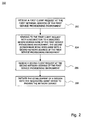
- Fig. 2 illustrates an exemplary flow diagram 200 of the steps performed in context with redirecting a client device, such as the client device 200 shown in Fig. 1 , to a network service in a communication network.
- the method steps may be performed by the network device 400 embedded in the first service provisioning environment 402 as illustrated in Fig. 1 or by any other central or distributed component located within or at the border of the first service provisioning environment.
- the method starts, in step 202, with receipt of a first client request at the first network address of a first service provisioning environment of a service provisioning domain.
- the first client request is a Hyper Text Transfer Protocol (HTTP) request.
- HTTP Hyper Text Transfer Protocol
- the first client request may relate to the establishment of a session during which a network service will be provided.
- the network service may be any service that can be provided by a network server, such as an e-banking service, an electronic purchasing transaction, or the like.
- a response to the first client request is generated and transmitted back to the client device.
- the response redirects the client device to a dedicated second domain name of the first service provisioning environment.
- This dedicated second domain name is resolvable into a second network address of the first service provisioning environment.
- a second client request of the client device having transmitted the first client request is received at the second network address of the first service provisioning environment.
- the client device has been informed about the designated second domain name of the first service provisioning environment, and this second domain name (due to its unique association with the first service provisioning environment) may then safely be resolved during any subsequent (browser-initiated or user-initiated) new resolutions without the risk of directing the client to a second service provisioning environment different from the first service provisioning environment in which a session will be or has been established.
- a final step 208 the establishment of a session with the requesting client device (over the second network address) is initiated in order to provide the requested network service.
- the session will typically involve the requesting client device as well as at least one server located within the first service provisioning environment.
- Fig. 3 shows a schematic flow diagram 300 illustrating the steps performed by a client device, such as the client device 200 shown in Fig. 1 , in context with being redirected to a network service in a communications network.
- the steps illustrated in the flow diagram 300 can be performed together with the steps shown in flow diagram 200 of Fig. 2 .
- a first client request is transmitted by the client device to a first network address of a first service provisioning environment of a service provisioning domain.
- the first service provisioning environment may be configured as shown in Fig. 1 (reference numeral 402) or in any other manner.
- the method proceeds with receipt of a redirection command from the first service provisioning environment in step 304.
- the redirection command redirects the client device to a dedicated second domain name of the first service provisioning environment, and this second domain name is resolvable into a second network address of the first service provisioning environment.
- step 306 the client device obtains the second network address of the first service provisioning environment.
- a domain name resolution may be performed.
- step 308 a second client request is transmitted to the second network address of the first service provisioning environment.
- a session for providing the requested network service is established within the first service provisioning environment.
- the second domain name obtained in step 304 is used further on by the client device during any (browser-initiated or user-initiated) subsequent domain name resolution processes during the ongoing session.
- the client device may locally associate the established session with the dedicated second domain name of the first service provisioning environment. Any subsequent domain name resolution based on the second domain name of the first service provisioning environment will then always yield the second network address of the first service provisioning environment, and not a network address of any other service provisioning environment that may exist in parallel to the first service provisioning environment in the service provisioning domain. This technique thus helps to ensure that any session-related signalling originating from the client device will always be routed to the ongoing session within the first service provisioning environment.
- Fig. 4 shows a schematic flow diagram 400 of a method for directing a client device, such as the client device 200 in Fig. 1 , to a network service in a communication network.
- the method steps illustrated in the flow diagram 400 may be combined with the method steps illustrated in the flow diagrams 200 and 300 of Figs. 2 and 3 , respectively.
- the method underlying the flow diagram 400 may be practised by the domain name resolution device 300 of Fig. 1 or any other device.
- the method starts in step 402 with maintaining a domain name resolution mechanism.
- This mechanism associates the domain names and network addresses of two or more service provisioning environments and may take the form of a database table.
- the domain name resolution mechanism associates a common first domain name of the multiple service provisioning environments with a dedicated first network address of each service provisioning environment, and a dedicated second domain name of each service provisioning environment with a second network address of the respective service provisioning environment.
- the method selectively disables a direction to one of the service provisioning environments by excluding the first network address of the corresponding service provisioning environment from domain name resolution.
- the specific first network address may simply be deleted, or it may be overwritten by a third network address.
- the third network address may belong to a mechanism that redirects a requesting client to the common first domain name of the service provisioning environments. Alternatively, or in addition, such a mechanism may delete any state information associating the requesting client with the service provisioning environment for which the first network address has been disabled.
- a two-layered load balancing mechanism having an upper (global) load balancing layer and a lower (local) load balancing layer will be described. While the global load balancing layer is provided for distributing workload among (in the non-limiting example) two service provisioning environments, the local load balancing layer is provided in each service provisioning environment for distributing workload among two or more local network servers that may constitute a service provisioning cluster.
- the service provisioning environments are set up at geographically spaced-apart sites to ensure that a disastrous event of only local impact will not lead to a complete network service outage (first redundancy aspect).
- the two service provisioning environments (hereinafter also called service provisioning sites or simply sites) are separated on the network layer (layer 3 in the OSI standard model). Any network breakdown or network mis-configuration in the service provisioning domain will thus typically lead to an outage of only one single site (second redundancy aspect).
- the main components of the communication network 500 include a client device 510, a domain name resolution mechanism 520 with additional global load balancing (or global traffic management, GTM) functionality, and two service provisioning environments 530, 530' located at geographically space-apart sites called "FLUR" on the one hand and "URDORF" on the other hand.
- the client device 510, the domain name resolution mechanism 520 and the service provisioning environments 530, 530' communicate with each other via the Internet 540.
- the Internet 540 harbours the domain name resolution mechanism (GTM) 520 as well as an Internet Service Provider (ISP) 550 associated with the client device 510. Any signalling to and from the client device 510 is routed via the IPS 550 as illustrated by the arrows in Fig. 5 .
- the client device 510 comprises a local storage (not shown) such as a hard disk or a random access memory (RAM) for at least temporarily storing state information.
- the state information may relate to a site and/or a session during which a network service is, has been or will be obtained.
- the state information includes at least a cookie 512 and table or list 514 for storing address-related information. The content and purpose of the cookie 512 and the table or list 514 will be explained in more detail below.
- this network component has access to a table 522 associating domain names and network addresses of the two service provisioning sites 530, 530'. If additional service provisioning sites are required, the corresponding domain names and network addresses will also be stored in the table 522.
- the two service provisioning sites 530, 530' have a similar configuration.
- a local load balancer 532 also called local traffic manager, LTM
- LTM local traffic manager
- the LTM 532 is a layer 2 component and locally routes any client requests to one of several Reverse Proxies (RP) 536.
- RP Reverse Proxies
- four RPs 536 are provided at each site 530, 530' each RP 536 having its dedicated network address (in the present case, an IP address such x.x.x.11, x.x.x.12, .
- each site 530, 530' could be installed at each site 530, 530'.
- Each of the RPs 536 is coupled between the LTM 532 and a web server (or web server instance) 538.
- the four RPs 536 installed at each site 530, 530' thus effectively shield the associated web servers 538 from the client device 510 and any other devices connected to the Internet 540.
- Each web server 538 comprises a first redirection listener 560 at port 111, a worker listener 562 at port 122 and a second redirection listener 564 at port 133.
- the two redirector listeners 560, 564 basically perform redirection tasks, whereas the worker listener 562 is in charge of establishing a session in context with the provision of the network service requested by the client device 510.
- Each of the listeners 560, 562, 564 of the web server 538 is configured to communicate with a dedicated translator 570, 572, 574 installed on the LTM 532.
- the translators 570, 572, 574 are each uniquely addressable by a dedicated network address at port 443.
- port 443 is reserved for encrypted Secure Socket Layer (SSL) signalling that will penetrate the firewall 534.
- SSL Secure Socket Layer
- the translation tasks of the translators 570, 572, 574 basely comprise Network Address Translation (NAT) and Port Address Translation (PAT) tasks to ensure that a client request received, for example, at the network address y.y.y.33 at port 443 by the translator 570 is forwarded to the network address of a selected one of the RPs 536 at the port of the proper listener.
- the translator 570 addressable by the client device 510 at the network address/port y.y.y.33:443 of site 530 forwards any client request to the first redirection listener 560 of the web server 538 connected to the first RP 536 at address/port x.x.x.11:111.
- the translator 570 performs a reverse-translation for any signalling received from the first redirection listener 560 and directed to the client device 510. Similar considerations apply to the two remaining translators 572 and 574.
- the requested network service may be an e-banking or any other application that is based on the session paradigm.
- a session will be understood as a lasting connection between the client device 510 and a worker instance 562 running on one of the web servers 538.
- the duration of the connection may range from a few seconds to several hours or longer.
- the connection will typically be terminated once the requested network service has been provided to the client device 510.
- the operational mode illustrated in Fig. 5 starts with a user of the client device 510 typing in the common domain name of the service provisioning domain in the appropriate field of a browser running on the client device 510.
- the user may activate a predefined link such as a browser bookmark to the common domain name.
- the common domain name of the service provisioning domain can be interpreted as the common domain name of the two service provisioning sites 530, 530'.
- this common domain name is constituted by the URL "https://connect.ubs.com”.
- the network addresses associated with this common domain name are not cached anywhere on the client device 510 or by the ISP 550. Accordingly, the initial state of the client device 510 will be as follows: Initial state of the client device in the scenario of Fig. 5 URL https://connect.ubs.com Site Cookie None DNS Cache None
- a DNS recurser (not shown) of the client device 510 will finally be directed to the GTM 520.
- the domain name "connect.ubs.com” is associated with two network address entries, namely y.y.y.33 on the one hand and y.y.y.44 on the other hand.
- the first network address y.y.y.33 is associated with the site "FLUR” 530 (more specifically with the translator 570 of the LTM 532 of site 530), and the second network address y.y.y.44 is associated with the site "URDORF" 530' (more specifically with the translator 570' of the LTM 532' of site 530').
- the two sites 530, 530' are addressable under the common domain name "connect.ubs.com", and this common domain name is resolvable into a dedicated network address y.y.y.33 of the site "FLUR” 530 and into another dedicated network address y.y.y.44 of the site "URDORF" 530'.
- the approach of assigning individual network addresses of several sites to a common domain name permits the implementation of a global load balancing mechanism and of redundancy on the site level.
- global load balancing is performed by the GTM 520, in which case the GTM 520 will return the selected network address of a single one of the sites 530, 530' (i.e. either y.y.y.33 or y.y.y.44) to the DNS recurser of the client device 510.
- the selection of the specific network address may be based on a round robin scheme, or it may be performed in a random manner. Other alternatives for selecting a network address in context with global load balancing exist also.
- the client device 510 receives from the GTM 520 a list that includes the network addresses of each available site 530, 530'.
- the client thus receives the two network addresses x.x.x.33 and x.x.x.44 from the GTM 520 and associates both network addresses with the domain name "connect.ubs.com" as becomes apparent from the local client table 514.
- the selection of a single one of the network addresses associated with "connect.ubs.com” will then be performed on the client device 510 (e. g. according to a round robin scheme or in a random manner or by the user).
- a second signalling step (2) the browser running on the client device 510 is trying to connect to a Hyper Text Transfer Protocol SSL (HTTPS) server at the network address y.y.y.33 and at the SSL port 443.
- HTTPS Hyper Text Transfer Protocol SSL
- the corresponding signalling is routed by the ISP 550 through the Internet to site 530, where it penetrates the firewall 534 and reaches translator 570 associated with the target address/port y.y.y.33:443.
- the LTM 532 Upon receipt of the client request in signalling step (2), the LTM 532 performs a local load balancing process and selects a single RP 536 (and an associated web server 538) for processing the client request.
- the selection performed in this regard by the LTM 532 may be based on any load balancing strategy including round robin and random schemes.
- the LTM 532 selects RP 536 with network address x.x.x.11. Since the client request is a first request that is not yet associated with an ongoing session and for which no state information is available, the LTM 532 forwards the client request to port 111 of the web server 436 after having performed the required NAT/PAT processes. As stated above, port 111 is associated with the first redirection listener 560.
- the first redirection listener 560 has various tasks.
- a first task comprises maintaining state information to enable a tracking of the client device 510 and of the browser running on the client device 510.
- a cookie 512 is set at the client device 510.
- the cookie 512 references the site "FLUR" 530 as illustrated by a single bullet in Fig. 5 .
- a corresponding cookie 512' referencing the site "URDORF" 530' will be graphically identified by two bullets (for illustrating purposes only).
- the first redirection listener 560 redirects the client device 510 to the dedicated domain name "connect1.ubs.com” of the site "FLUR” 530. This redirection can be performed by a HTTP response message including a 3xx redirection status code such as 302 (or in any other way such as by a form-based redirect).
- the browser running on the client device 510 may be configured or instructed to mandatorily return both the cookie (if cookie support is provided) and the cookie variable in any subsequent client request.
- the client device 510 Once the client device 510 has received the dedicated domain name "connect1.ubs.com” of the site "FLUR" 530 in signalling step (2), the client device 510 will request the network address associated with this domain name. To this end, a further signalling step is performed between the client device 510 and the GTM 520 in a similar way as discussed above with reference to signalling step (1).
- Domain name resolution by the GTM 520 based on the content of the table 522 reveals that the network address associated with "connect1.ubs.com” is set to y.y.y.55.
- the client device 510 will thus open a connection to y.y.y.55 at SSL port 443 with cookie 512 set to the site "FLUR" 530.
- the corresponding client request (including the cookie variable and, if cookies are supported, the cookie 512 itself) is received by the translator 572 associated with the network address y.y.y.55 at port 443 at the LTM 532.
- the translator 572 will forward the client request according to a local load balancing strategy to the first available RP 536 at port 122.
- the client request is forwarded to the RP 536 at address x.x.x.11 on port 122.
- port 122 belongs to worker listener 562, which will then establish an SSL session to provide the requested network service. All future requests and responses exchanged between the client device 510 and the web server instance 538 will be sent over the established SSL session. Once the network service has been provided, the session may be terminated again.
- the cookie 512 that has been set in signalling step (2) may then either be deleted or deactivated or simply remains unchanged.
- the operational mode illustrated in Fig. 6 is a regular operational mode that illustrates the behaviour of the network 500 in case a client request is generated from an earlier defined link such as a browser bookmark.
- Any bookmark that has been created earlier by the browser running on the client device 510 during a session that was handled by the site "URDORF" 530' will point to the domain name of this site (i.e. to "connenct2.ubs.com”).
- a user may directly type in the designated domain name "connect2.ubs.com” in the appropriate field of this browser.
- the initial state of client device 510 will in each case be the following: Initial state of the client device 510 in the scenario of Fig. 6 URL https://connect2.ubs.com Site Cookie None DNS Cache None
- the client device 510 Upon activating the bookmark pointing to "connect2.ubs.com", or upon confirming a corresponding user input, the client device 510 will resolve the network address of the domain name "connect2.ubs.com” to y.y.y.66 during a domain name resolution process involving the GTM 520 and the GTM table 522.
- the corresponding signalling is similar to signalling step (1) discussed above in context with Fig. 5 .
- the client device 510 will connect in a first signalling step (1) to the site "URDORF" 530'. That is, the client device 510 sends a client request via SSL and through the firewall 534' to the translator 572' associated with the network address y.y.y.66 at port 443.
- the translator 572' first performs NAT/PAT and then forwards the client request to the worker listener 562' running on the web server 538' of a selected RP 536'.
- the corresponding worker process will first evaluate state information associated with the requesting client device 510 and will thus determine that client device 510 does not yet have a site cookie.
- the client device Upon receipt of the redirection command in signalling step (1), the client device proceeds with further signalling steps (2), (3) and (4).
- these three further signalling steps are identical to signalling steps (1), (2) and (3), respectively, discussed above in connection with Fig. 5 .
- a first signalling step (1) as illustrated in Fig. 7 will be performed.
- the client device 510 resolves, with the help of the GTM 520, the network address of "connect2.ubs.com” to y.y.y.66.
- a next signalling step (2) the client connects to the network address y.y.y.66 at SSL port 433. This connection will lead the client device 510 to the worker listener 562' at port 122 of the web server 538' as explained above (signalling step (1) in Fig. 6 ).
- the worker listener 562' at port 122 of the site "URDORF" 530' recognises from the available state information (i.e. from cookie 512) that the requesting client device 510 has an ongoing session at the site "FLUR" 530. Consequently, the worker listener 562' redirects the client device 520 to a worker listener at the site "FLUR” 530 via a resolution of the domain name "connect1.ubs.com".
- the client device 510 connects to the appropriate translator 572 at the site "FLUR” 530 and gets forwarded therefrom to the associated worker listener 562 handling the ongoing session.
- FIG. 8 A still further operational mode will now be discussed with reference to Fig. 8 .
- the client device 510 has a standing session with the site "FLUR" 530 while the user activates a bookmark or any other link pointing to the common domain name "connect.ubs.com”.
- the initial state of the client device 510 is summarised in the table below: Initial state of the client device 510 in the scenario of Fig. 8 URL https://connect.ubs.com Site Cookie FLUR DNS Cache None
- the client device 510 has a standing session with the site "FLUR" 530 (signalling step (1)) and, during this session, the user activates a link pointing to the common domain name "connect.ubs.com” of the service provisioning sites 530, 530'.
- the browser of the client device 510 will instruct the GTM 520 to perform a domain name resolution process for "connect.ubs.com".
- the GTM 520 will return a list including the two network addresses x.x.x.33 and x.x.x.44 as explained earlier.
- the client device 510 selects the x.x.x.44 address.
- the client device 510 will be directed in a third signalling step (3) to the first redirector listener 560' of the site "URDORF" 530'.
- the first redirector listener 560' will evaluate if any state information is available and will thus determine, based on the cookie 512, that the client device 510 has an ongoing session with the site "FLUR” 530.
- the first redirector listener 560' thus redirects the client directly to "connect1.ubs.com” (and thus to the corresponding worker process at the site "FLUR” 530).
- the client device 510 in a fourth signalling step (4) connects back to his original worker process 562.
- the redirection logic of the first redirection listener 560, 560' is triggered by receipt of an incoming HTTP client request (step 910).
- the first redirection listener 560, 560' determines if state information is available for the requesting client device 510.
- the state information is maintained in the form of a cookie 512 referencing a particular one of the two service provisioning sites 530, 530'.
- step 912 If it is determined in step 912 that a cookie 512 is actually available, the redirection logic proceeds with step 914 and determines if the first redirection listener 560, 560' processing the incoming client request belongs to the specific service provisioning site 530, 530' referenced in the cookie 512. If this determination in step 914 results in the finding that the client request has reached the correct site, the redirection logic proceeds with step 914 and redirects the client device 510 to the worker listener 562, 562' of the local site.
- step 914 If, on the other hand, the determination performed step 914 yields the result that the cookie references a site different from the site in which the client request is evaluated, the redirection process continues with step 918 and redirects the requesting client device 510 to the specific site referenced in the cookie.
- step 920 a site cookie 512 is set and, additionally, a cookie variable is set by writing a site reference in the redirection URL as discussed above. Moreover, the requesting client device 510 is redirected to the local worker listener 562, 562' of the present site 530, 530'. This situation corresponds to the scenario shown in Fig. 5 .
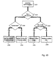
- Fig. 10 illustrates the redirection logic of the worker listener 572, 572' as implemented, for example, in the network scenarios of Figs. 5 to 8 .
- the redirection process starts with the receipt of an incoming HTTP client request by the worker listener 562, 562' of one the sites 530, 530' (step 1010).
- state information i.e., a cookie 512
- a cookie 512 it is determined in a next step 1030 if the cookie 512 references the site of the specific worker listener 562, 562' processing the client request. If, based on evaluation of the cookie, it is determined in step 1030 that the cookie 512 references the correct site 530, 530', the cookie variable is removed and the client request is forwarded to a specific application and processed in a next step 1040. Otherwise (i.e. in case the cookie 512 references another site) the redirection process continues with redirecting the client device 510 to the site referenced in the cookie 512 (step 1050). This redirection result corresponds to the scenario illustrated in Fig. 7 .
- step 1020 If it is determined in step 1020 that no state information is available, it is determined in a next step 1060 if the requesting client device 510 has a valid cookie variable (i.e., references the correct site 530, 530'). If a valid cookie variable can be found in step 1060, the redirection process continues with a redirection to an error page in step 1070.
- the error page requests the user of the client device 510 to activate the cookie support feature of his/her browser. In this regard, the fact that no cookie is returned while the request is accompanied by a valid cookie variable is interpreted as an indication that cookie support has been disabled at the client site.
- the client device 510 is redirected in step 1080 to the common domain name of the sites 530, 530' (i.e. to the global URL "https://connect.ubs.com") for starting the process shown in Fig. 5 .
- Fig. 11 it will be assumed that the site "URDORF" 530' has been taken out of service some time ago. In order to prevent that global load balancing will still direct any requesting client 510 to the site 530' taken out of service, the domain name resolution table 522 of the GTM 520 has been updated accordingly by excluding the network address y.y.y.44 from global domain name resolution. This can be done by deleting or blocking the corresponding network addresses in the table 522.
- the scenario illustrated in Fig. 11 is similar to the first connection scenario shown in Fig. 5 with the exception of the reconfigured GTM 520.
- the initial state of the client device 510 is shown in the following table. Initial state of the client device 510 in the scenario of Fig. 11 URL https://connect.ubs.com Site Cookie None DNS Cache None
- the signalling starts with a first signalling step (1) in which the client device 510 requests the network address corresponding to the common domain name "connect.ubs.com".
- the first signalling step (1) is performed in a similar manner as the first signalling step (1) shown in Fig. 5 with the exception that the GTM 522 returns only a single network address, namely the network address y.y.y.33 of the site "FLUR” 530.
- the client device 510 will thus automatically be directed to the site "FLUR” 530 still in service and has no possibility of selecting the other site “URDORF" 530' compared to the scenario of Fig. 5 .
- the table 522 of the GTM 520 will include N-1 network address entries for the common domain name "connect.ubs.com". Consequently, the GTM 520 will return N-1 network addresses to the requesting client device 510 to enable the selection of a specific site. Alternatively, the selection among the N-1 network addresses could of course also be performed by the GTM 520.
- the client device 510 initiates a second signalling step (2) that will result in a redirection as illustrated by signalling step (3).
- Signalling steps (2) and (3) of Fig. 11 then correspond to signalling steps (2) and (3) of Fig. 5 .
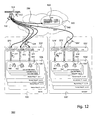
- FIG. 12 An additional operational mode illustrated in Fig. 12 corresponds to a graceful take-over from the site "URDORF" 530' to the site “FLUR” 530 during an ongoing session. It will be assumed that the site “URDORF” 530' is about to be shut down for maintenance purposes. Therefore, the GTM 520 has already been reconfigured to point only to the site "FLUR” 530 as explained above in connection with Fig. 11 .
- the LTM 532' effected by this shutdown will wait until all connections have been transferred to another site 530.
- the actual shutdown of the site 530' will only be triggered when there are no more client devices 510 connected to this site 530'.
- the initial state of the client device 510 is shown in the following table: Initial state of the client device 510 in the scenario of Fig. 12 URL https://connect2.ubs.com Site Cookie URDORF DNS Cache CONNECT2 -> URDORF
- signalling step (1) indicates that the client device 510 has a standing session and is logged in at the site "URDORF" 530'.
- the GTM 520 has been reconfigured to point only to the site “FLUR” 530 due to an imminent shutdown of the site “URDORF” 530'.
- the reconfiguration of the GTM 520 concerns two entries in the GTM table 522. First, the network address y.y.y.44 of the site "URDORF" 530' will be removed or blocked so that a resolution of the common domain name "connect.ubs.com” will not direct the client 510 to the site "URDORF" 530'.
- the network address associated with the designated domain name "connenct2.ubs.com” of the site "URDORF" 530' will be changed such that it directs the client device 510 (via the translator 574) to the second redirection listener 564 of the site "FLUR” 530.
- domain name resolution will return the network address y.y.y.77 to the client device 510 in signalling step (2).
- the network address y.y.y.77 returned in signalling step (2) will direct the client device 510 to the second redirection listener 564 of the site "FLUR” 530 as indicated by signalling step (3).
- the second redirection listener 564 will perform some dedicated tasks.
- a first task includes a deletion of all state information (including cookies) associating the client device 510 with the site "URDORF" 530' that has to be taken out of service.
- An optional second task redirects the client device 510 to the common domain name "connect.ubs.com" to ensure a workload distribution in case of a service provisioning domain including three or more service provisioning sites.
- a redirection is not mandatory, so that the second redirection listener 564 may set a cookie 512 referencing the site "FLUR" 530 and redirect the client device 510 directly to "connect1.ubs.com", i.e. to the first redirection listener 560. Additionally, the second redirection listener 564 may trigger the display of an information message on a monitor of the client device 510 to inform the user about the ongoing redirection process (as a new authentication may be required).
- the client device 510 will in a next signalling step (4) contact the first redirection listener 560.
- the first redirection listener 560 will redirect the client device 512 to the local worker listener 562 as explained above in connection with the signalling steps of (2) and (3) of Fig. 5 .
- the client device 510 connects to the worker instance 562 on the web server 538 of the site "FLUR" 530. There, the client device 510 will have to log-in again (new authentication) because the log-in context (site token) is not shared between the sites 530, 530'.
- the client device 510 activates a link to a site 530' that has been taken out of service while the client device 510 has an ongoing session on another site 530.
- the GTM table 520 has previously been reconfigured as discussed in context with Fig. 12 .
- the initial state of the client device 510 will thus be as follows. Initial state of client device 510 in the scenario of Fig. 13 URL https://connect2.ubs.com Site Cookie FLUR DNS Cache None
- the client device 510 is connected to and has an authenticated session with the site "FLUR” 530.
- the user activates a link to the designated domain name "connect2.ubs.com” of the site “URDORF” 530' that has been taken out of service.
- a second signalling step (2) the GTM 520 resolves "connect2.ubs.com” into the network address x.x.x.77.
- the network address x.x.x.77 directs the client device 510 to the second redirection listener 564 via translator 574.
- This is illustrated by signalling step (3).
- the second redirection listener 564 evaluates the state information (i.e. the cookie 512) associated with the requesting client device 510 and thus determines that the client device 510 has an ongoing session at the site "FLUR" and a valid session context.
- the second redirection listener 564 will thus redirect the client device 510 directly to the local worker listener 562 at "connect1.ubs.com".
- the client device 510 thus connects with his existing session context to the worker listener 562 to continue the ongoing session.
- the redirection process starts, in step 1410, with receipt of an incoming HTTP client request by the second redirection listener 564, 564'.
- a next step 1420 is determined if state information (i.e. a cookie 512) is available for the requesting client device 510.
- step 1430 if the state information references the particular site of the second redirection listener 564, 564' or a wrong site. In the case the correct site is referenced, the redirection process continues with step 1440, and the client device 510 is redirected to the local worker listener 562, 562'. This scenario has been discussed above with reference to Fig. 13 .
- step 1450 all cookies are deleted and the requesting client device 510 is redirected to the common domain name of the service provisioning sites 530, 530' (i.e. to the global URL "connect.ubs.com") to ensure that a global load balancing is performed. This basically corresponds to the scenario discussed above with reference to Fig. 12 .
- step 1420 it may be determined in step 1420 that no state information is available for the requesting client device 510 (i.e. that no cookie 512 has been set).
- the redirection process continues with step 1460 and with a redirection to the common domain name "connect.ubs.com" for a global load balancing.
- the redirection in cases of scheduled and unscheduled site outages occurs via a reconfiguration of the GTM table 522 and, more specifically, of the DNS entries included therein.
- DNS entries changed on the GTM 520 will have to be propagated through the Internet 540 to the client device 510. Any caching on the way from the GTM 520 to the client device 510 (such as in the DNS of the ISP 550) will slow down the whole propagation process. Therefore, the validity period of the DNS response should be set to a minimum value.
- State information such as cookies and cookie variables is not only helpful to implement the redirection logic, but it may also be an important factor for tracking established sessions such as e-banking or electronic purchase sessions.
- there are three methods to preserve state information in the form of a "session state" in a HTTPS session namely the SSL session ID, the session number in the URL (URL-rewrite) and the setting of a session cookie.
- the use of the SSL session ID may not work in cases in which client devices sit behind an SSL RP, which is re-using sessions.
- the use of a session number in the URL is not transparent to the end users and is stored in the browsing history (which can be undesirable in some cases).
- session cookies in combination with URL rewriting for detecting cookie support, might often be a good solution not only for redirection control but also for session tracking. For this reason, it may be desirable to trap client devices with no cookie support with a redirection to a corresponding error page as illustrated by block 1070 in Fig. 10 .
- the trapping may be implemented in a "site cookie setting filter" as follows: if no valid cookie is available, the first redirector 560, 560' not only sets a site cookie, but also writes the cookie in the redirection URL (cookie variable) as shown in box 920 of Fig. 9 .
Priority Applications (2)
| Application Number | Priority Date | Filing Date | Title |
|---|---|---|---|
| EP07013525A EP2015236A1 (fr) | 2007-07-10 | 2007-07-10 | Technique de rédirection dans un réseau de communication |
| US11/898,733 US8127018B2 (en) | 2007-07-10 | 2007-09-14 | Redirection techniques in a communication network |
Applications Claiming Priority (1)
| Application Number | Priority Date | Filing Date | Title |
|---|---|---|---|
| EP07013525A EP2015236A1 (fr) | 2007-07-10 | 2007-07-10 | Technique de rédirection dans un réseau de communication |
Publications (1)
| Publication Number | Publication Date |
|---|---|
| EP2015236A1 true EP2015236A1 (fr) | 2009-01-14 |
Family
ID=38935773
Family Applications (1)
| Application Number | Title | Priority Date | Filing Date |
|---|---|---|---|
| EP07013525A Ceased EP2015236A1 (fr) | 2007-07-10 | 2007-07-10 | Technique de rédirection dans un réseau de communication |
Country Status (2)
| Country | Link |
|---|---|
| US (1) | US8127018B2 (fr) |
| EP (1) | EP2015236A1 (fr) |
Cited By (7)
| Publication number | Priority date | Publication date | Assignee | Title |
|---|---|---|---|---|
| WO2010068451A2 (fr) * | 2008-11-25 | 2010-06-17 | Citrix Systems, Inc. | Systèmes et procédés pour la persistance de sites gslb |
| US7925694B2 (en) | 2007-10-19 | 2011-04-12 | Citrix Systems, Inc. | Systems and methods for managing cookies via HTTP content layer |
| US8090877B2 (en) | 2008-01-26 | 2012-01-03 | Citrix Systems, Inc. | Systems and methods for fine grain policy driven cookie proxying |
| EP3364630A1 (fr) * | 2017-02-20 | 2018-08-22 | Nokia Solutions and Networks Oy | Procédé de distribution de charge et appareil de réseau |
| CN112583952A (zh) * | 2020-12-09 | 2021-03-30 | 北京金山云网络技术有限公司 | 重定向调度处理方法、装置、系统及相关设备、存储介质 |
| CN112712360A (zh) * | 2019-10-25 | 2021-04-27 | 腾讯科技(深圳)有限公司 | 充值方法及装置 |
| US20210297353A1 (en) * | 2020-03-19 | 2021-09-23 | EMC IP Holding Company LLC | Method, device, and computer program product for accessing application system |
Families Citing this family (10)
| Publication number | Priority date | Publication date | Assignee | Title |
|---|---|---|---|---|
| KR100969470B1 (ko) | 2008-07-24 | 2010-07-14 | 에스케이 텔레콤주식회사 | 리소스 보안 시스템 및 리소스 보안 방법 |
| US8363663B2 (en) * | 2009-04-02 | 2013-01-29 | The Boeing Company | Methods and apparatus for routing data to nodes |
| US8671221B2 (en) * | 2010-11-17 | 2014-03-11 | Hola Networks Ltd. | Method and system for increasing speed of domain name system resolution within a computing device |
| US8533786B2 (en) * | 2010-12-02 | 2013-09-10 | Salesforce.Com, Inc. | Method and apparatus for protecting against attacks from outside content |
| CA2824203C (fr) | 2011-01-12 | 2021-03-30 | Level 3 Communications, Llc | Noms de domaine personnalises dans un reseau de distribution de contenu (cdn) |
| US8874790B2 (en) | 2011-12-30 | 2014-10-28 | Verisign, Inc. | DNS package in a partitioned network |
| US10594650B2 (en) * | 2013-07-12 | 2020-03-17 | Skyhook Wireless, Inc. | Propagating attributes between network addresses |
| US10097503B2 (en) | 2013-09-27 | 2018-10-09 | Fastly, Inc. | Content node network address selection for content delivery |
| CA2867585A1 (fr) * | 2013-10-15 | 2015-04-15 | Coho Data Inc. | Procedes, dispositifs et systemes pour coordonner une communication basee sur un reseau dans des systemes de serveur distribues avec commutation sdn |
| US10044609B2 (en) * | 2014-02-04 | 2018-08-07 | Fastly, Inc. | Communication path selection for content delivery |
Family Cites Families (8)
| Publication number | Priority date | Publication date | Assignee | Title |
|---|---|---|---|---|
| US5708780A (en) * | 1995-06-07 | 1998-01-13 | Open Market, Inc. | Internet server access control and monitoring systems |
| US5987523A (en) * | 1997-06-04 | 1999-11-16 | International Business Machines Corporation | Applet redirection for controlled access to non-orginating hosts |
| US6718387B1 (en) * | 1997-12-10 | 2004-04-06 | Sun Microsystems, Inc. | Reallocating address spaces of a plurality of servers using a load balancing policy and a multicast channel |
| US7441045B2 (en) * | 1999-12-13 | 2008-10-21 | F5 Networks, Inc. | Method and system for balancing load distribution on a wide area network |
| AU2001275327A1 (en) * | 2000-06-09 | 2001-12-24 | Charles P. Brown | Method and system for protecting domain names |
| US7509369B1 (en) * | 2001-07-11 | 2009-03-24 | Swsoft Holdings, Ltd. | Balancing shared servers in virtual environments |
| US7631084B2 (en) * | 2001-11-02 | 2009-12-08 | Juniper Networks, Inc. | Method and system for providing secure access to private networks with client redirection |
| JP4241660B2 (ja) * | 2005-04-25 | 2009-03-18 | 株式会社日立製作所 | 負荷分散装置 |
-
2007
- 2007-07-10 EP EP07013525A patent/EP2015236A1/fr not_active Ceased
- 2007-09-14 US US11/898,733 patent/US8127018B2/en not_active Expired - Fee Related
Non-Patent Citations (4)
| Title |
|---|
| ALTAVISTA: "Multi-site session persistence with ZXTM GLB and ZXTM", pages 1 - 2, XP002466007, Retrieved from the Internet <URL:http://de.altavista.com/web/results?itag=ody&pg=aq&aqmode=s&aqa=Multi-site+session+persistence+with+ZXTM+GLB+and+ZXTM&aqp=&aqo=&aqn=&kgs=0&kls=0&d2=0&dt=dtrange&dfr%5Bd%5D=1&dfr%5Bm%5D=1&dfr%5By%5D=1980&dto%5Bd%5D=30&dto%5Bm%5D=6&dto%5By%5D=2007&filetype=&rc=dmn&swd=&lh=&nbq=10> [retrieved on 20080124] * |
| BROADBAND-TESTING: "Zeus Extensible Traffic Manager (ZXTM), A Broadband-Testing Report", 2004, La Calade, 11700 Moux, Aude, France, pages 1 - 29, XP002466006, Retrieved from the Internet <URL:http://www.zeus.com/documents/en/br/broadband-testing_zxtm.pdf> [retrieved on 20080124] * |
| ZEUS TECHNOLOGY LIMITED: "Multi-site session persistence with ZXTM GLB and ZXTM", 30 June 2007 (2007-06-30), Retrieved from the Internet <URL:http://www.zeus.com/documents/en/ZX/ZXTM_GLB_multisite_persistence.pdf> [retrieved on 20080124] * |
| ZEUS TECHNOLOGY LIMITED: "ZXTM BLG, Scaling your services with ZXTM Global Load Balancer", 30 June 2007 (2007-06-30), pages 1 - 13, XP002466005, Retrieved from the Internet <URL:http://www.zeus.com/documents/en/Sc/Scaling_with_ZXTM_GLB.pdf> [retrieved on 20080124] * |
Cited By (16)
| Publication number | Priority date | Publication date | Assignee | Title |
|---|---|---|---|---|
| US7925694B2 (en) | 2007-10-19 | 2011-04-12 | Citrix Systems, Inc. | Systems and methods for managing cookies via HTTP content layer |
| US8090877B2 (en) | 2008-01-26 | 2012-01-03 | Citrix Systems, Inc. | Systems and methods for fine grain policy driven cookie proxying |
| US8769660B2 (en) | 2008-01-26 | 2014-07-01 | Citrix Systems, Inc. | Systems and methods for proxying cookies for SSL VPN clientless sessions |
| US9059966B2 (en) | 2008-01-26 | 2015-06-16 | Citrix Systems, Inc. | Systems and methods for proxying cookies for SSL VPN clientless sessions |
| WO2010068451A2 (fr) * | 2008-11-25 | 2010-06-17 | Citrix Systems, Inc. | Systèmes et procédés pour la persistance de sites gslb |
| WO2010068451A3 (fr) * | 2008-11-25 | 2010-09-02 | Citrix Systems, Inc. | Systèmes et procédés pour la persistance de sites gslb |
| US8260926B2 (en) | 2008-11-25 | 2012-09-04 | Citrix Systems, Inc. | Systems and methods for GSLB site persistence |
| US8566450B2 (en) | 2008-11-25 | 2013-10-22 | Citrix Systems, Inc. | Systems and methods for GSLB site persistence |
| EP3364630A1 (fr) * | 2017-02-20 | 2018-08-22 | Nokia Solutions and Networks Oy | Procédé de distribution de charge et appareil de réseau |
| WO2018149684A1 (fr) * | 2017-02-20 | 2018-08-23 | Nokia Solutions And Networks Oy | Procédé de distribution de charge et appareil de réseau |
| CN112712360A (zh) * | 2019-10-25 | 2021-04-27 | 腾讯科技(深圳)有限公司 | 充值方法及装置 |
| CN112712360B (zh) * | 2019-10-25 | 2024-02-13 | 腾讯科技(深圳)有限公司 | 充值方法及装置 |
| US20210297353A1 (en) * | 2020-03-19 | 2021-09-23 | EMC IP Holding Company LLC | Method, device, and computer program product for accessing application system |
| CN113497815A (zh) * | 2020-03-19 | 2021-10-12 | 伊姆西Ip控股有限责任公司 | 用于访问应用系统的方法、设备和计算机程序产品 |
| US11558301B2 (en) * | 2020-03-19 | 2023-01-17 | EMC IP Holding Company LLC | Method, device, and computer program product for accessing application system |
| CN112583952A (zh) * | 2020-12-09 | 2021-03-30 | 北京金山云网络技术有限公司 | 重定向调度处理方法、装置、系统及相关设备、存储介质 |
Also Published As
| Publication number | Publication date |
|---|---|
| US8127018B2 (en) | 2012-02-28 |
| US20090019143A1 (en) | 2009-01-15 |
Similar Documents
| Publication | Publication Date | Title |
|---|---|---|
| US8127018B2 (en) | Redirection techniques in a communication network | |
| CN111314499B (zh) | 一种域名代理方法、装置、设备及可读存储介质 | |
| US8706906B2 (en) | Multipath routing process | |
| CN108886540B (zh) | 域名解析方法、装置及计算机可读存储介质 | |
| EP1552413B1 (fr) | Procédé et système pour fournir un contenu à la demande sur un serveur d'origine | |
| US9009327B2 (en) | Systems and methods for providing IIP address stickiness in an SSL VPN session failover environment | |
| US8132247B2 (en) | Systems and methods for authorizing a client in an SSL VPN session failover environment | |
| EP3080972B1 (fr) | Procédé et noeud de réseau pour mettre en cache du contenu web | |
| US8156199B1 (en) | Centralized control of client-side domain name resolution using VPN services | |
| US7680954B2 (en) | Proxy DNS for web browser request redirection in public hotspot accesses | |
| US8930554B2 (en) | Transferring session data between network applications accessible via different DNS domains | |
| US20070061465A1 (en) | Host migration system | |
| CN113037878B (zh) | 一种cdn数据访问方法、系统及电子设备 | |
| US10645061B2 (en) | Methods and systems for identification of a domain of a command and control server of a botnet | |
| WO2016069592A1 (fr) | Systèmes et procédés de distribution de contenu | |
| JP2004524602A (ja) | ピアツーピア環境においてキャッシュされた資源間における資源の相同性 | |
| WO2007143551A2 (fr) | Messagerie instantanée utilisant le navigateur | |
| EP2343867A1 (fr) | Système et procédé de réduction de trafic intranet sur des liens de goulot d'étranglement dans un réseau de télécommunication | |
| CA2680210A1 (fr) | Moteur de recherche internet | |
| JP2007207231A (ja) | ネットワークにおける分散サービスへのアクセス法 | |
| US20230198987A1 (en) | Systems and methods for controlling accessing and storing objects between on-prem data center and cloud | |
| EP1387301A2 (fr) | Etablissement de connexions réseau | |
| EP2963880B1 (fr) | Procede d'envoi et de traitement de donnees et routeur | |
| CN103138961B (zh) | 服务器控制方法、被控服务器及中心控制服务器 | |
| US20040225708A1 (en) | Establishment of network connections |
Legal Events
| Date | Code | Title | Description |
|---|---|---|---|
| PUAI | Public reference made under article 153(3) epc to a published international application that has entered the european phase |
Free format text: ORIGINAL CODE: 0009012 |
|
| AK | Designated contracting states |
Kind code of ref document: A1 Designated state(s): AT BE BG CH CY CZ DE DK EE ES FI FR GB GR HU IE IS IT LI LT LU LV MC MT NL PL PT RO SE SI SK TR |
|
| AX | Request for extension of the european patent |
Extension state: AL BA HR MK RS |
|
| 17P | Request for examination filed |
Effective date: 20090128 |
|
| 17Q | First examination report despatched |
Effective date: 20090304 |
|
| AKX | Designation fees paid |
Designated state(s): AT BE BG CH CY CZ DE DK EE ES FI FR GB GR HU IE IS IT LI LT LU LV MC MT NL PL PT RO SE SI SK TR |
|
| RAP1 | Party data changed (applicant data changed or rights of an application transferred) |
Owner name: UBS BUSINESS SOLUTIONS AG |
|
| STAA | Information on the status of an ep patent application or granted ep patent |
Free format text: STATUS: THE APPLICATION HAS BEEN REFUSED |
|
| 18R | Application refused |
Effective date: 20171211 |