EP2015136A1 - Projector and brightness adjusting method - Google Patents
Projector and brightness adjusting method Download PDFInfo
- Publication number
- EP2015136A1 EP2015136A1 EP08010811A EP08010811A EP2015136A1 EP 2015136 A1 EP2015136 A1 EP 2015136A1 EP 08010811 A EP08010811 A EP 08010811A EP 08010811 A EP08010811 A EP 08010811A EP 2015136 A1 EP2015136 A1 EP 2015136A1
- Authority
- EP
- European Patent Office
- Prior art keywords
- projector
- projector body
- rotation operation
- output device
- image output
- Prior art date
- Legal status (The legal status is an assumption and is not a legal conclusion. Google has not performed a legal analysis and makes no representation as to the accuracy of the status listed.)
- Granted
Links
- 238000000034 method Methods 0.000 title claims description 9
- 230000003287 optical effect Effects 0.000 claims abstract description 70
- 238000001514 detection method Methods 0.000 claims abstract description 15
- 238000003780 insertion Methods 0.000 claims description 94
- 230000037431 insertion Effects 0.000 claims description 94
- 239000004973 liquid crystal related substance Substances 0.000 description 20
- 238000012545 processing Methods 0.000 description 10
- 239000000758 substrate Substances 0.000 description 6
- 230000000694 effects Effects 0.000 description 5
- 230000000903 blocking effect Effects 0.000 description 4
- 210000002858 crystal cell Anatomy 0.000 description 4
- 238000010586 diagram Methods 0.000 description 4
- NJPPVKZQTLUDBO-UHFFFAOYSA-N novaluron Chemical compound C1=C(Cl)C(OC(F)(F)C(OC(F)(F)F)F)=CC=C1NC(=O)NC(=O)C1=C(F)C=CC=C1F NJPPVKZQTLUDBO-UHFFFAOYSA-N 0.000 description 4
- 239000003086 colorant Substances 0.000 description 3
- 230000001105 regulatory effect Effects 0.000 description 3
- 230000001276 controlling effect Effects 0.000 description 2
- 238000012986 modification Methods 0.000 description 2
- 230000004048 modification Effects 0.000 description 2
- 238000012544 monitoring process Methods 0.000 description 2
- 238000000926 separation method Methods 0.000 description 2
- 238000000465 moulding Methods 0.000 description 1
- 230000002093 peripheral effect Effects 0.000 description 1
Images




Classifications
-
- H—ELECTRICITY
- H04—ELECTRIC COMMUNICATION TECHNIQUE
- H04N—PICTORIAL COMMUNICATION, e.g. TELEVISION
- H04N5/00—Details of television systems
- H04N5/74—Projection arrangements for image reproduction, e.g. using eidophor
-
- G—PHYSICS
- G03—PHOTOGRAPHY; CINEMATOGRAPHY; ANALOGOUS TECHNIQUES USING WAVES OTHER THAN OPTICAL WAVES; ELECTROGRAPHY; HOLOGRAPHY
- G03B—APPARATUS OR ARRANGEMENTS FOR TAKING PHOTOGRAPHS OR FOR PROJECTING OR VIEWING THEM; APPARATUS OR ARRANGEMENTS EMPLOYING ANALOGOUS TECHNIQUES USING WAVES OTHER THAN OPTICAL WAVES; ACCESSORIES THEREFOR
- G03B29/00—Combinations of cameras, projectors or photographic printing apparatus with non-photographic non-optical apparatus, e.g. clocks or weapons; Cameras having the shape of other objects
-
- G—PHYSICS
- G03—PHOTOGRAPHY; CINEMATOGRAPHY; ANALOGOUS TECHNIQUES USING WAVES OTHER THAN OPTICAL WAVES; ELECTROGRAPHY; HOLOGRAPHY
- G03B—APPARATUS OR ARRANGEMENTS FOR TAKING PHOTOGRAPHS OR FOR PROJECTING OR VIEWING THEM; APPARATUS OR ARRANGEMENTS EMPLOYING ANALOGOUS TECHNIQUES USING WAVES OTHER THAN OPTICAL WAVES; ACCESSORIES THEREFOR
- G03B21/00—Projectors or projection-type viewers; Accessories therefor
- G03B21/14—Details
- G03B21/145—Housing details, e.g. position adjustments thereof
Definitions
- the present invention relates to a projector and a brightness adjusting method.
- a projector that includes a projector body, which has a light modulating device that modulates light emitted from a light source according to input image information to thereby form an optical image and a projection optical device that projects the formed optical image in an enlarged manner, and an image output device that outputs the image information to the projector body, the projector body and the image output device being configured to be able to rotate relative to each other (for example, refer to JP-A-2005-99617 ).
- the projector disclosed in JP-A-2005-99617 is configured such that a projecting section (projector body) is connected with a DVD (digital versatile disk) reproduction section (image output device) through a connecting section provided above the DVD reproduction section and the projecting section can rotate relative to the DVD reproduction section.
- a projecting section projector body
- DVD digital versatile disk
- image output device image output device
- An advantage of some aspects of the invention is that it provides a projector, which can be comfortably used by a user in a case where a projector body and an image output device are in a relative rotation operation state or a recording medium is in an insertion or ejection operation state, and a brightness adjusting method.
- a projector including a projector body, which has a light modulating device that modulates light emitted from a light source according to input image information to thereby form an optical image and a projection optical device that projects the formed optical image in an enlarged manner, an image output device that outputs the image information to the projector body, and a connection mechanism for connecting the projector body and the image output device with each other such that the projector body and the image output device can rotate relative to each other includes: a rotation operation detecting unit that detects a relative rotation operation of the projector body and the image output device; and a control unit that controls the projector body and the rotation operation detecting unit.
- the control unit includes: a rotation operation recognition portion that recognizes whether or not the projector body and the image output device are in a relative rotation operation state on the basis of a detection result of the rotation operation detecting unit; and a brightness adjusting portion that adjusts the brightness of light emitted from the projection optical device when the rotation operation recognition portion has recognized that the projector body and the image output device are in the relative rotation operation state.
- the brightness adjusting portion adjusts the brightness of light emitted from the projection optical device when the rotation operation recognition portion has recognized that the projector body and the image output device are in the relative rotation operation state.
- the brightness adjustment portion performs adjustment for reducing the brightness of light emitted from the projection optical device, for example, by performing adjustment for reducing the brightness of light emitted from the light source or adjustment for reducing the brightness of the optical image formed by the light modulating device, a user can comfortably use the projector without an uncomfortable feeling even in a condition where the projector body and the image output device are in the relative rotation operation state.
- the rotation operation detecting unit includes a plurality of switches for detecting whether or not the projector body and the image output device are located at a plurality of predetermined relative positions, and the rotation operation recognition portion recognizes that the projector body and the image output device are in the relative rotation operation state when all of the plurality of switches have detected that the projector body and the image output device are not located at the predetermined relative positions.
- predetermined relative positions of the projector body and the image output device are set to first and second relative positions.
- a surface of the image output device provided with an operation portion and a front-end-side surface in the direction of projection performed by the projection optical device are located at the same side in the case of the first relative position and located at opposite sides in the case of the second relative position.
- two switches for detecting whether or not the projector body and the image output device are located at the relative positions are provided as a rotation operation detecting unit.
- the rotation operation recognition portion recognizes that the projector body and the image output device are in the relative rotation operation state, and the brightness adjustment portion performs adjustment for reducing the brightness of light emitted from the projection optical device.
- the rotation operation recognition portion recognizes that the projector body and the image output device are not in the relative rotation operation state, and the brightness adjustment portion does not adjust the brightness of light emitted from the projection optical device.
- the rotation operation recognition portion not only can recognize that the projector body and the image output device are in the relative rotation operation state but also can reliably recognize that the projector body and the image output device are located at the respective relative positions.
- the projector in which the projector body and the image output device are configured to be able to rotate relative to each other can be suitably used by setting each relative position to a position suitable for use of the projector, such as the first and second relative positions.
- a projector including a projector body, which has a light modulating device that modulates light emitted from a light source according to input image information to thereby form an optical image and a projection optical device that projects the formed optical image in an enlarged manner, and an image output device that has an insertion and ejection opening for inserting and ejecting a recording medium and that outputs the image information to the projector body includes: an insertion and ejection operation detecting unit that detects an insertion or ejection operation of the recording medium; and a control unit that controls the projector body and the insertion and ejection operation detecting unit.
- the control unit includes: an insertion and ejection operation recognition portion that recognizes whether or not the recording medium is in an insertion or ejection operation state on the basis of a detection result of the insertion and ejection operation detecting unit; and a brightness adjusting portion that adjusts the brightness of light emitted from the projection optical device when the insertion and ejection operation recognition portion has recognized that the recording medium is in the insertion or ejection operation state.
- the brightness adjusting portion adjusts the brightness of light emitted from the projection optical device when the insertion and ejection operation recognition portion has recognized that the recording medium is in the insertion and ejection operation state. Accordingly, for example, since the brightness adjustment portion performs adjustment for reducing the brightness of light emitted from the projection optical device, the user can comfortably use the projector without an uncomfortable feeling even in a condition where a recording medium is in an insertion or ejection operation state.
- the brightness adjusting portion adjusts the brightness of light emitted from the projection optical device by controlling the light modulating device.
- the brightness adjustment portion can quickly adjust the brightness of light emitted from the projection optical device compared with a case of performing adjustment for reducing the brightness of light emitted from a light source.
- a brightness adjusting method used in a projector including a projector body, which has a light modulating device that modulates light emitted from a light source according to input image information to thereby form an optical image and a projection optical device that projects the formed optical image in an enlarged manner, and an image output device that has an insertion and ejection opening for inserting and ejecting a recording medium and that outputs the image information to the projector body includes: executing insertion and ejection operation recognition for recognizing whether or not the recording medium is in an insertion or ejection operation state; and executing brightness adjustment for adjusting the brightness of light emitted from the projection optical device when it is recognized that the recording medium is in the insertion or ejection operation state in the executing of the insertion and ejection operation recognition.
- Fig. 1 is a perspective view illustrating a projector according to a first embodiment as viewed from a front side.
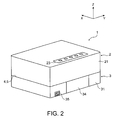
- Fig. 2 is a perspective view illustrating the projector according to the embodiment as viewed from a rear side.
- Fig. 3 is an exploded perspective view illustrating the projector according to the embodiment as viewed from the front side.
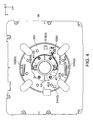
- Fig. 4 is a view illustrating a top plate as viewed from the below in a state where the projector according to the embodiment is temporarily fixed at the first temporarily fixed position.
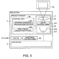
- Fig. 5 is a block diagram illustrating the schematic configuration of the projector according to the embodiment.
- Fig. 6 is a flow chart illustrating brightness adjustment processing of the projector according to the embodiment.
- Fig. 7 is a block diagram illustrating the schematic configuration of a projector according to a second embodiment.
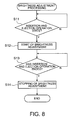
- Fig. 8 is a flow chart illustrating brightness adjustment processing of the projector according to the embodiment.
- Fig. 1 is a perspective view illustrating a projector 1 as viewed from a front side
- Fig. 2 is a perspective view illustrating the projector 1 as viewed from a rear side
- Fig. 3 is an exploded perspective view illustrating the projector 1 as viewed from the front side.
- the direction from the rear side of the projector 1 to the front side thereof is set to an X axis and two axes perpendicular to the X axis are set to a Y axis (horizontal axis) and a Z axis (vertical axes), respectively, for the convenience of explanation.
- Y axis horizontal axis
- Z axis vertical axes
- the projector 1 includes: a projector body 2 that forms an optical image by modulating light emitted from a light source according to input image information and projects the formed optical image in an enlarged manner; a DVD player 3 that outputs image information to the projector body 2; a connection mechanism 4 that rotatably connects the projector body 2 and the DVD player 3 with each other; a rotation regulating mechanism 5 that regulates the rotation of the projector body 2 and the DVD player 3; and a rotation operation detecting unit 6 (refer to Fig. 4 ) that detects a relative rotation operation of the projector body 2 and the DVD player 3.
- the rotation operation detecting unit 6 will be described in detail later.
- the projector body 2 is placed at an upper direction side (+Z-axis direction side) of the DVD player 3 and includes: an upper housing 21 formed in an approximately rectangular parallelepiped shape; a projection lens 22 exposed on a front surface (surface at +X-axis direction side) of the upper housing 21; and an operation panel 23 provided at a rear side (-X-axis direction side) of an upper surface (surface at +Z-axis direction side) of the upper housing 21.
- the operation panel 23 is used to execute operations, such as starting and adjustment of the projector 1, and operations, such as reproduction and stopping of the DVD player 3.
- the DVD player 3 executes reproduction, stopping, and the like of image information, sound information, and the like recorded in a recording medium, such as a DVD, inserted in the DVD player 3 when the DVD operation panel 23 is operated.
- the DVD player 3 serving as an image output device outputs image information and the like recorded in a recording medium to the projector body 2 through an image cable (not shown) by reproducing the recording medium, such as a DVD, recorded with image information and the like as digital data. As shown in Figs.
- the DVD player 3 is disposed at a lower side (-Z-axis direction side) of the projector body 2 and includes: a lower housing 31 formed in an approximately rectangular parallelepiped shape; a DVD insertion and ejection opening 32 provided approximately in the middle of a front surface of the lower housing 31; a DVD operation display unit 33 provided below the DVD insertion and ejection opening 32; and an interface cover 34 and an inlet connector 35 provided on a rear surface (surface at -X-axis direction side) of the lower housing 31.
- the DVD insertion and ejection opening 32 is a slot-in type insertion and ejection opening into which a recording medium, such as a DVD, is inserted and from which the recording medium is ejected.
- the DVD player 3 reproduces image information and the like recorded in the recording medium inserted in the DVD insertion and ejection opening 32.
- an ejection switch 32A for ejecting a recording medium is attached next to the DVD insertion and ejection opening 32.
- the ejection switch 32A will be described in detail later.
- the DVD operation display unit 33 is a unit that displays states, such as reproduction and stopping, of the DVD player 3. A user can check the states, such as reproduction and stopping of a recording medium, by viewing the DVD operation display unit 33.
- various kinds of interface connectors such as an image input terminal used to input image information from the outside to the projector 1, are provided inside the interface cover 34.
- the interface cover 34 protects the interface connectors.
- the interface cover 34 may not be provided.
- the inlet connector 35 is a connector used to connect an AC power cable from the outside and is exposed without being covered by the interface cover 34.
- connection mechanism 4 includes: a plate-shaped member 41 fixed to a bottom plate 24 of the projector body 2; a rotation member 42 that is fixed to the plate-shaped member 41 and is rotatably attached to a top plate 36 of the DVD player 3; and a plurality of divided circular ring members 43 that attach the rotation member 42 to the top plate 36.
- the projection lens 22 (refer to Fig. 1 ) exposed from the upper housing 21, the DVD insertion and ejection opening 32 (refer to Fig. 1 ) provided in the lower housing 31, and the like are not shown.
- the plate-shaped member 41 is a plate-shaped member formed in an approximately cross shape in plan view and has four ends extending in four directions in a state where the four ends are approximately perpendicular to each other.
- the rotation member 42 is fixed to approximately the middle of the plate-shaped member 41 with a plurality of screws.
- the rotation member 42 includes a rotation member body 421 having an approximately cylindrical shape and an extending portion 422 provided so as to be approximately perpendicular to one end of the rotation member body 421 at a side of the top plate 36 in the axial direction and to extend toward the outside.
- an approximately disc-like pedestal 361 protruding upward is formed at the approximately middle position of the top plate 36 by press molding, for example.
- an approximately circular opening 361A is formed at the approximately middle position of the pedestal 36.
- the rotation member 42 is inserted into the opening 361A from the above in the state where the rotation member 42 is fixed to the plate-shaped member 41.
- the divided circular ring members 43 are members obtained by dividing a plate-shaped circular ring member, which has approximately the same internal diameter as the external diameter of the rotation member body 421, into two portions and are formed to have approximately the same thickness as a gap between the extending portion 422 and the top plate 36 in a state where the rotation member 42 is inserted into the opening 361A.
- the divided circular ring members 43 are inserted such that the rotation member body 421 is interposed in a gap between the top plate 36 and the extending portion 422 and are fixed to the top plate 36 with a plurality of screws.
- the top plate 36 is fixed to the lower housing 31 with a plurality of screws.
- the rotation regulating mechanism 5 includes stopper portions 51A and 51B, which are provided at two positions on a right side surface side (+Y-axis direction side) and a left side surface side (-Y-axis direction side) in the peripheral edge of the pedestal 361 and are bent so as to protrude upward, and click springs 52A and 52B attached at two positions on a front surface side (+X-axis direction side) and a rear surface side (-X-axis direction side).
- the stopper portions 51A and 51B are in contact with the plate-shaped member 41 to thereby regulate the rotation of the plate-shaped member 41 in a predetermined direction.
- the stopper portion 51A is in contact with the plate-shaped member 41 in a state where the projection lens 22 of the projector body 2 and the DVD insertion and ejection opening 32 of the DVD player 3 are positioned at the same side, that is, in states shown in Figs. 1 and 3 and regulates the rotation of the plate-shaped member 41 in a clockwise direction (arrow A in Fig. 3 ) as viewed from the above.
- the stopper portion 51B is in contact with the plate-shaped member 41 in a state where the projection lens 22 and the DVD insertion and ejection opening 32 are positioned at opposite sides, that is, in a state shown in Fig. 2 and regulates the rotation of the plate-shaped member 41 in a counterclockwise direction (arrow B in Fig. 3 ).
- the click springs 52A and 52B apply to the plate-shaped member 41 a resistive force against the rotation opposite rotation in the predetermined direction regulated by the stopper portions 51A and 51B when the plate-shaped member 41 comes in contact with the stopper portions 51A and 51B.
- the plate-shaped member 41 is temporarily fixed in a state where the plate-shaped member 41 is in contact with the stopper portions 51A and 51B. Furthermore, in the present embodiment, it is assumed that a temporarily fixed position in a state where the plate-shaped member 41 is in contact with the stopper portion 51A is a first temporarily fixed position (refer to Figs. 1 to 3 ) and a temporarily fixed position in a state where the plate-shaped member 41 is in contact with the stopper portion 51B is a second temporarily fixed position.
- Fig. 4 illustrates the top plate 36 as viewed from the below in a state where the projector 1 is temporarily fixed at the first temporarily fixed position.
- the rotation operation detecting unit 6 includes: switches 61A and 61B each of which is attached to approximately the middle of each of the divided circular ring members 43 and has an approximately rectangular shape in plan view; and a substrate 62 for switches that is attached to the pedestal 361 so as to detect conduction and non-conduction of the switches 61A and 61B.
- a shaft 611 is provided in the corner of each of the switches 61A and 61B so as to protrude toward the outside on an approximately extending line of a diagonal line of each of the switches 61A and 61B.
- the shaft 611 can freely rotate around a corner of each of the switches 61A and 61B and is biased toward a side of the rotation member 42 with respect to the corner of each of the switches 61A and 61B.
- the switches 61A and 61B are not electrically conducted in a state where a load is not applied to the shaft 611 (state of the switch 61B in Fig. 4 ).
- the switches 61A and 61B are electrically conducted when a load is applied to the shaft 611 and the shaft 611 is inserted such that the shaft 611 is approximately parallel to surfaces of the switches 61A and 61B facing the rotation member 42 (state of the switch 61A in Fig. 4 ).
- a protruding portion 422A protruding toward the click spring 52A in a state where the projector 1 is temporarily fixed at the first temporarily fixed position is formed in the extension 422 of the rotation member 42.
- the protruding portion 422A is formed at the position where a load is applied to the shaft 611 of the switch 61A in a state where the projector 1 is temporarily fixed at the first temporarily fixed position and a load is applied to the shaft 611 of the switch 61B in a state where the projector 1 is temporarily fixed at the second temporarily fixed position.
- the switch 61A in a state where the projector 1 is temporarily fixed at the first temporarily fixed position, the switch 61A is electrically conducted and the switch 61B is not electrically conducted.
- the switch 61A in a state where the projector 1 is temporarily fixed at the second temporarily fixed position, the switch 61A is not electrically conducted and the switch 61B is electrically conducted. Accordingly, the switches 61A and 61B detect whether or not the projector body 2 and the DVD player 3 are located at the first temporarily fixed position (first relative position) or the second temporarily fixed position (second relative position), respectively.
- the substrate 62 for switches is a circuit board for detecting conduction (ON state) and non-conduction (OFF state) of the switches 61A and 61B and is controlled by a control unit 26 to be described later. In addition, the substrate 62 for switches outputs each detected ON or OFF state to the control unit 26.
- Fig. 5 is a block diagram illustrating the schematic configuration of the projector 1.
- the projector body 2 is schematically configured to include an image projection unit 25 and the control unit 26.
- the image projection unit 25 forms an optical image by modulating light emitted from a light source according to image information and projects the formed optical image onto a projection surface of a screen Sc or the like in an enlarged manner.
- the image projection unit 25 includes a light source device 251, a liquid crystal panel 252, and the above-described projection lens 22.
- the light source device 251 includes a light source lamp 253 formed by using a high-pressure discharge lamp, and the light source lamp 253 emits light toward the liquid crystal panel 252.
- the light source device 251 may also include various kinds of self-luminous elements, such as a light-emitting diode, a laser diode, and an organic EL element, instead of the light source lamp 253.
- the liquid crystal panel 252 serving as a light modulating device is a transmissive liquid crystal panel.
- the liquid crystal panel 252 forms an optical image by changing the arrangement of liquid crystal molecules included in liquid crystal cells (not shown) on the basis of image information and performing modulation according to image data by transmitting or blocking light emitted from the light source lamp 253 and then emits the optical image to the projection lens 22.
- the projection lens 22 serving as a projection optical device is configured as a group lens in which a plurality of lenses are provided within a cylindrical lens barrel (not shown) and projects the optical image emitted from the liquid crystal panel 252 toward the screen Sc in an enlarged manner. In addition, a projection image based on the emitted optical image is displayed on the screen Sc.
- the projector body 2 includes a color light separation optical device for separating light, which is emitted from the light source lamp 253, into light components corresponding to three colors of RGB (Red, Green, and Blue). Furthermore, the liquid crystal panel 252 is provided corresponding to three colors of RGB separated by the color light separation optical device. In addition, the projector body 2 includes a mixing optical device that generates an optical image, which expresses a color image, by mixing optical images corresponding to three colors.
- the control unit 26 is configured to include a CPU (central processing unit), for example, and controls the projector body 2 and the substrate 62 for switches.
- the control unit 26 includes a rotation operation recognition portion 261 and a brightness adjusting portion 262.
- the rotation operation recognition portion 261 recognizes whether or not the projector body 2 and the DVD player 3 are in a relative rotation operation state on the basis of an ON or OFF state of each of the switches 61A and 61B output from the substrate 62 for switches.
- the brightness adjusting portion 262 adjusts the brightness of the light emitted from the projection lens 22 when the rotation operation recognition portion 261 has recognized that the projector body 2 and the DVD player 3 are in the relative rotation operation state.
- Fig. 6 is a flow chart illustrating brightness adjustment processing of the projector 1.
- the projector 1 executes the following brightness adjustment processing while projecting an optical image, which is formed according to image information, onto the screen Sc in an enlarged manner.
- the rotation operation recognition portion 261 recognizes whether or not the projector body 2 and the DVD player 3 are in a relative rotation operation state by monitoring an ON or OFF state of each of the switches 61A and 61B output from the substrate 62 for switches (step S1: rotation operation recognition step).
- the rotation operation recognition portion 261 recognizes that the projector 1 is temporarily fixed at the first temporarily fixed position when the switch 61A is in an ON state and the switch 61B is in an OFF state. In addition, the rotation operation recognition portion 261 recognizes that the projector 1 is temporarily fixed at the second temporarily fixed position when the switch 61A is in an OFF state and the switch 61B is in an ON state.
- the rotation operation recognition portion 261 recognizes that the projector body 2 and the DVD player 3 are in the relative rotation operation state when all of the two switches 61A and 61B are in OFF states, that is, when the projector body 2 and the DVD player 3 are not at the first temporarily fixed position and the second temporarily fixed position.
- step S2 brightness adjustment step
- the brightness adjusting portion 262 performs adjustment for reducing the brightness of light emitted from the projection lens 22 by outputting to the liquid crystal panel 252 image information for blocking light emitted from the light source lamp 253 in all liquid crystal cells, that is, image information for causing a display image, which is displayed on the screen Sc, to be the entirely black image.
- the brightness adjusting portion 262 does not adjust the brightness of light emitted from the projection lens 22 when the rotation operation recognition portion 261 has recognized that the projector body 2 and the DVD player 3 are not in the relative rotation operation state, that is, when the projector 1 is located at the first temporarily fixed position or the second temporarily fixed position. Accordingly, in this case, image information recorded in a recording medium inserted in the DVD insertion and ejection opening 32 is input to the liquid crystal panel 252.
- step S2 the rotation operation recognition portion 261 recognizes whether or not the projector body 2 and the DVD player 3 have ended the relative rotation operation (step S3: rotation operation end recognition step).
- step S4 brightness adjustment stopping step
- the brightness adjustment processing of the projector 1 is executed by executing steps S1 to S4 described above.
- the projector 1 according to the present embodiment has the following effects.
- the brightness adjusting portion 262 performs adjustment for reducing the brightness of light emitted from the projection lens 22 when the rotation operation recognition portion 261 has recognized that the projector body 2 and the DVD player 3 are in the relative rotation operation state, a user can comfortably use the projector 1 without an uncomfortable feeling even in a condition where the projector body 2 and the DVD player 3 are in the relative rotation operation state.
- the rotation operation recognition portion 261 not only can recognize that the projector body 2 and the DVD player 3 are in the relative rotation operation state but also can reliably recognize that the projector body 2 and DVD player 3 are located at the respective temporarily fixed positions.
- the first temporarily fixed position and the second temporarily fixed position are set to positions suitable for use of the projector 1, the projector 1 in which the projector body 2 and the DVD player 3 are configured to be able to rotate relative to each other can be suitably used.
- the brightness adjusting portion 262 performs adjustment for reducing the brightness of light emitted from the projection lens 22 by outputting to the liquid crystal panel 252 the image information for blocking light emitted from the light source lamp 253 in all liquid crystal cells, the brightness of the light emitted from the projection lens 22 can be quickly adjusted compared with a case of performing adjustment for reducing the brightness of light emitted from the light source lamp 253.
- the brightness adjusting portion 262 adjusts the brightness of light emitted from the projection lens 22 when the rotation operation recognition portion 261 has recognized that the projector body 2 and the DVD player 3 are in the relative rotation operation state.
- the projector 1A according to the present embodiment is different from the projector 1 according to the first embodiment in that an insertion and ejection operation recognition portion 263 for recognizing whether or not a recording medium is in an insertion or ejection operation state is included and a brightness adjusting portion 262A adjusts the brightness of light emitted from the projection lens 22 when the insertion and ejection operation recognition portion 263 has recognized that the recording medium is in the insertion or ejection operation state.
- Fig. 7 is a block diagram illustrating the schematic configuration of the projector 1A.
- a DVD player 3A includes an insertion and ejection operation detecting unit 37.
- the insertion and ejection operation detecting unit 37 is configured to include an insertion detection switch 371 for detecting insertion of a recording medium and an ejection switch 32A for performing ejection of a recording medium.
- the insertion detection switch 371 is a mechanical switch provided inside a DVD insertion and ejection opening. When a part of a recording medium is inserted from the DVD insertion and ejection opening 32, the insertion detection switch 371 detects the inserted recording medium. In addition, when the recording medium is detected by the insertion detection switch 371, the DVD player 3A pulls the inserted recording medium to be placed thereinside.
- the ejection switch 32A is a switch for making the DVD player 3A start ejection of a recording medium when pressed. When the ejection switch 32A is pressed, the DVD player 3A ejects the recording medium, which is placed inside, to the outside.
- the insertion detection switch 371 and the ejection switch 32A are controlled by a control unit 26A.
- the insertion detection switch 371 outputs a state of detection of a recording medium to the control unit 26A and the ejection switch 32A outputs a pressed state to the control unit 26A.
- the control unit 26A controls a projector body 2A and the insertion and ejection operation detecting unit 37 and includes the insertion and ejection operation recognition portion 263 and the brightness adjusting portion 262A.
- the insertion and ejection operation recognition portion 263 recognizes whether or not a recording medium is in an insertion or ejection operation state on the basis of states output from the insertion detection switch 371 and the ejection switch 32A.
- the brightness adjusting portion 262A adjusts the brightness of light emitted from the projection lens 22 when the insertion and ejection operation recognition portion 263 has recognized that the recording medium is in an insertion or ejection operation state.
- Fig. 8 is a flow chart illustrating brightness adjustment processing of the projector 1A.
- the projector 1A executes the following brightness adjustment processing while projecting an optical image, which is formed according to image information, onto the screen Sc in an enlarged manner.
- the insertion and ejection operation recognition portion 263 recognizes whether or not a recording medium is in an insertion or ejection operation state by monitoring states of insertion and ejection output from the insertion and ejection operation detecting unit 37 (step S11: inserting operation recognition step).
- the insertion and ejection operation recognition portion 263 recognizes a period of time until placement of a recording medium in the DVD player 3A is completed after the recording medium is detected by the insertion detection switch 371 and a period of time until the recording medium is completely ejected from the DVD player 3A after the ejection switch 32A is pressed as an insertion and ejection operation state of the recording medium.
- step S12 brightness adjustment step
- the brightness adjusting portion 262A performs adjustment for reducing the brightness of light emitted from the projection lens 22 by outputting to the liquid crystal panel 252 image information for blocking light emitted from the light source lamp 253 in all liquid crystal cells.
- the insertion and ejection operation recognition portion 263 recognizes whether or not the insertion and ejection operation of the recording medium has ended (step S13: insertion and ejection operation end recognition step).
- the brightness adjusting portion 262A stops adjusting the brightness of light emitted from the projection lens 22 (step S14: brightness adjustment stopping step).
- the brightness adjustment processing of the projector 1A is executed by executing steps S11 to S14 described above.
- the brightness adjusting portion 262A adjusts the brightness of light emitted from the projection lens 22 when the insertion and ejection operation recognition portion 263 has recognized that a recording medium is in an insertion or ejection operation state, a user can comfortably use the projector 1A without an uncomfortable feeling even in a condition where a recording medium is in an insertion or ejection operation state.
- the rotation operation detecting unit and the insertion and ejection operation detecting unit 37 are configured to include switches, such as the switches 61A and 61B or the insertion detection switch 371, and the ejection switch 32A.
- switches such as the switches 61A and 61B or the insertion detection switch 371, and the ejection switch 32A.
- an optical sensor may also be used. That is, components for detecting the relative rotation operation and the insertion and ejection operation are preferably used.
- the brightness adjusting portions 262 and 262A adjust the brightness of light emitted from the projection lens 22 by controlling the liquid crystal panel 252.
- light emitted from a light source may be reduced or light emitted from a projection optical device may be blocked by a shutter or the like. That is, components capable of adjusting the brightness of light emitted from a projection optical device are preferably used.
- the brightness adjusting portion 262A adjusts the brightness of light emitted from the projection lens 22 when the insertion and ejection operation recognition portion 263 has recognized that a recording medium is in an insertion or ejection operation state.
- the brightness may also be adjusted only when the rotation operation recognition portion 261 has recognized that the projector 1 is temporarily fixed at the first temporarily fixed position and the insertion and ejection operation recognition portion 263 has recognized that the recording medium is in an insertion or ejection operation state.
- the insertion and ejection operation recognition portion 263 and the brightness adjusting portion 262A are provided in the projector 1A configured such that the projector body 2 and the DVD player 3 can rotate relative to each other.
- a projector body and an image output device may not be configured to rotate relative to each other. That is, a projector having an insertion and ejection opening for inserting and ejecting a recording medium is preferably used.
- the transmissive liquid crystal panel 252 is adopted.
- the invention is not limited to the transmissive liquid crystal panel 252.
- a reflective liquid crystal panel may be adopted or a digital micromirror device (DMD) may also be adopted.
- DMD digital micromirror device
- the 'DMD' is a trademark of Texas Instrument, Inc., U.S.
- the DVD players 3 and 3A are exemplified as image output devices.
- a video player may be used as an image output device. That is, a device that outputs image information to a projector body is preferably used.
- the invention can be used for a projector and can be suitably used particularly for a projector including a projector body and an image output device.
Landscapes
- Physics & Mathematics (AREA)
- General Physics & Mathematics (AREA)
- Engineering & Computer Science (AREA)
- Multimedia (AREA)
- Signal Processing (AREA)
- Projection Apparatus (AREA)
- Transforming Electric Information Into Light Information (AREA)
- Liquid Crystal (AREA)
Abstract
Description
- The present invention relates to a projector and a brightness adjusting method.
- There is known a projector that includes a projector body, which has a light modulating device that modulates light emitted from a light source according to input image information to thereby form an optical image and a projection optical device that projects the formed optical image in an enlarged manner, and an image output device that outputs the image information to the projector body, the projector body and the image output device being configured to be able to rotate relative to each other (for example, refer to
JP-A-2005-99617 - The projector disclosed in
JP-A-2005-99617 - However, in the case of the projector disclosed in
JP-A-2005-99617 - Furthermore, in the case of the projector disclosed in
JP-A-2005-99617 - An advantage of some aspects of the invention is that it provides a projector, which can be comfortably used by a user in a case where a projector body and an image output device are in a relative rotation operation state or a recording medium is in an insertion or ejection operation state, and a brightness adjusting method.
- According to an aspect of the invention, a projector including a projector body, which has a light modulating device that modulates light emitted from a light source according to input image information to thereby form an optical image and a projection optical device that projects the formed optical image in an enlarged manner, an image output device that outputs the image information to the projector body, and a connection mechanism for connecting the projector body and the image output device with each other such that the projector body and the image output device can rotate relative to each other includes: a rotation operation detecting unit that detects a relative rotation operation of the projector body and the image output device; and a control unit that controls the projector body and the rotation operation detecting unit. The control unit includes: a rotation operation recognition portion that recognizes whether or not the projector body and the image output device are in a relative rotation operation state on the basis of a detection result of the rotation operation detecting unit; and a brightness adjusting portion that adjusts the brightness of light emitted from the projection optical device when the rotation operation recognition portion has recognized that the projector body and the image output device are in the relative rotation operation state.
- In the above-described configuration, the brightness adjusting portion adjusts the brightness of light emitted from the projection optical device when the rotation operation recognition portion has recognized that the projector body and the image output device are in the relative rotation operation state. Thus, since the brightness adjustment portion performs adjustment for reducing the brightness of light emitted from the projection optical device, for example, by performing adjustment for reducing the brightness of light emitted from the light source or adjustment for reducing the brightness of the optical image formed by the light modulating device, a user can comfortably use the projector without an uncomfortable feeling even in a condition where the projector body and the image output device are in the relative rotation operation state.
- In the projector according to the aspect of the invention, preferably, the rotation operation detecting unit includes a plurality of switches for detecting whether or not the projector body and the image output device are located at a plurality of predetermined relative positions, and the rotation operation recognition portion recognizes that the projector body and the image output device are in the relative rotation operation state when all of the plurality of switches have detected that the projector body and the image output device are not located at the predetermined relative positions.
- For example, in the case where an operation portion, such as an insertion and ejection opening of a DVD, is provided in the image output device, predetermined relative positions of the projector body and the image output device are set to first and second relative positions. Here, a surface of the image output device provided with an operation portion and a front-end-side surface in the direction of projection performed by the projection optical device are located at the same side in the case of the first relative position and located at opposite sides in the case of the second relative position. In addition, two switches for detecting whether or not the projector body and the image output device are located at the relative positions are provided as a rotation operation detecting unit.
- Furthermore, in this manner, it is possible to make the position of an operation portion of the image output device close to a user of the projector in a state where the user of the projector is provided opposite a screen since the user of the projector can locate the projector body and the image output device at the first relative position when the projector is disposed in a place behind the user and can locate the projector body and the image output device at the second relative position when the projector is disposed in a place before the user. As a result, the operability can be improved.
- According to those described above, in the case where the projector body and the image output device are not located at the first and second relative positions, two switches all detect that the projector body and the image output device are not located at the predetermined relative positions. Accordingly, the rotation operation recognition portion recognizes that the projector body and the image output device are in the relative rotation operation state, and the brightness adjustment portion performs adjustment for reducing the brightness of light emitted from the projection optical device. On the other hand, in the case where the projector body and the image output device are located at the first and second relative positions, either one of the two switches detects that the projector body and the image output device are located at the predetermined relative positions. Accordingly, the rotation operation recognition portion recognizes that the projector body and the image output device are not in the relative rotation operation state, and the brightness adjustment portion does not adjust the brightness of light emitted from the projection optical device.
- That is, according to such a configuration, the rotation operation recognition portion not only can recognize that the projector body and the image output device are in the relative rotation operation state but also can reliably recognize that the projector body and the image output device are located at the respective relative positions. Thus, the projector in which the projector body and the image output device are configured to be able to rotate relative to each other can be suitably used by setting each relative position to a position suitable for use of the projector, such as the first and second relative positions.
- According to another aspect of the invention, a projector including a projector body, which has a light modulating device that modulates light emitted from a light source according to input image information to thereby form an optical image and a projection optical device that projects the formed optical image in an enlarged manner, and an image output device that has an insertion and ejection opening for inserting and ejecting a recording medium and that outputs the image information to the projector body includes: an insertion and ejection operation detecting unit that detects an insertion or ejection operation of the recording medium; and a control unit that controls the projector body and the insertion and ejection operation detecting unit. The control unit includes: an insertion and ejection operation recognition portion that recognizes whether or not the recording medium is in an insertion or ejection operation state on the basis of a detection result of the insertion and ejection operation detecting unit; and a brightness adjusting portion that adjusts the brightness of light emitted from the projection optical device when the insertion and ejection operation recognition portion has recognized that the recording medium is in the insertion or ejection operation state.
- In the above-described configuration, the brightness adjusting portion adjusts the brightness of light emitted from the projection optical device when the insertion and ejection operation recognition portion has recognized that the recording medium is in the insertion and ejection operation state. Accordingly, for example, since the brightness adjustment portion performs adjustment for reducing the brightness of light emitted from the projection optical device, the user can comfortably use the projector without an uncomfortable feeling even in a condition where a recording medium is in an insertion or ejection operation state.
- In the projector according to the aspect of the invention, preferably, the brightness adjusting portion adjusts the brightness of light emitted from the projection optical device by controlling the light modulating device.
- According to such a configuration, the brightness adjustment portion can quickly adjust the brightness of light emitted from the projection optical device compared with a case of performing adjustment for reducing the brightness of light emitted from a light source.
- According to still another aspect of the invention, a brightness adjusting method used in a projector that includes a projector body, which has a light modulating device that modulates light emitted from a light source according to input image information to thereby form an optical image and a projection optical device that projects the formed optical image in an enlarged manner, and an image output device that outputs the image information to the projector body and that is configured such that the projector body and the image output device can rotate relative to each other includes: executing rotation operation recognition for recognizing whether or not the projector body and the image output device are in a relative rotation operation state; and executing brightness adjustment for adjusting the brightness of light emitted from the projection optical device when it is recognized that the projector body and the image output device are in the relative rotation operation state in the executing of the rotation operation recognition.
- According to the above-described configuration, the same operations and effects as those of the above projector can be achieved.
- According to still another aspect of the invention, a brightness adjusting method used in a projector including a projector body, which has a light modulating device that modulates light emitted from a light source according to input image information to thereby form an optical image and a projection optical device that projects the formed optical image in an enlarged manner, and an image output device that has an insertion and ejection opening for inserting and ejecting a recording medium and that outputs the image information to the projector body includes: executing insertion and ejection operation recognition for recognizing whether or not the recording medium is in an insertion or ejection operation state; and executing brightness adjustment for adjusting the brightness of light emitted from the projection optical device when it is recognized that the recording medium is in the insertion or ejection operation state in the executing of the insertion and ejection operation recognition.
- According to the above-described configuration, the same operations and effects as those of the above projector can be achieved.
- The invention will be described with reference to the accompanying drawings, wherein like numbers reference like elements.
-
Fig. 1 is a perspective view illustrating a projector according to a first embodiment as viewed from a front side. -
Fig. 2 is a perspective view illustrating the projector according to the embodiment as viewed from a rear side. -
Fig. 3 is an exploded perspective view illustrating the projector according to the embodiment as viewed from the front side. -
Fig. 4 is a view illustrating a top plate as viewed from the below in a state where the projector according to the embodiment is temporarily fixed at the first temporarily fixed position. -
Fig. 5 is a block diagram illustrating the schematic configuration of the projector according to the embodiment. -
Fig. 6 is a flow chart illustrating brightness adjustment processing of the projector according to the embodiment. -
Fig. 7 is a block diagram illustrating the schematic configuration of a projector according to a second embodiment. -
Fig. 8 is a flow chart illustrating brightness adjustment processing of the projector according to the embodiment. - Hereinafter, an embodiment of the invention will be described with reference to the accompanying drawings.
-
Fig. 1 is a perspective view illustrating aprojector 1 as viewed from a front side, andFig. 2 is a perspective view illustrating theprojector 1 as viewed from a rear side.Fig. 3 is an exploded perspective view illustrating theprojector 1 as viewed from the front side. Moreover, inFigs. 1 to 3 , the direction from the rear side of theprojector 1 to the front side thereof is set to an X axis and two axes perpendicular to the X axis are set to a Y axis (horizontal axis) and a Z axis (vertical axes), respectively, for the convenience of explanation. The same is true for the following drawings. - As shown in
Figs. 1 to 3 , theprojector 1 includes: aprojector body 2 that forms an optical image by modulating light emitted from a light source according to input image information and projects the formed optical image in an enlarged manner; aDVD player 3 that outputs image information to theprojector body 2; aconnection mechanism 4 that rotatably connects theprojector body 2 and theDVD player 3 with each other; arotation regulating mechanism 5 that regulates the rotation of theprojector body 2 and theDVD player 3; and a rotation operation detecting unit 6 (refer toFig. 4 ) that detects a relative rotation operation of theprojector body 2 and theDVD player 3. In addition, the rotationoperation detecting unit 6 will be described in detail later. - As shown in
Figs. 1 and2 , theprojector body 2 is placed at an upper direction side (+Z-axis direction side) of theDVD player 3 and includes: anupper housing 21 formed in an approximately rectangular parallelepiped shape; aprojection lens 22 exposed on a front surface (surface at +X-axis direction side) of theupper housing 21; and anoperation panel 23 provided at a rear side (-X-axis direction side) of an upper surface (surface at +Z-axis direction side) of theupper housing 21. Theoperation panel 23 is used to execute operations, such as starting and adjustment of theprojector 1, and operations, such as reproduction and stopping of theDVD player 3. TheDVD player 3 executes reproduction, stopping, and the like of image information, sound information, and the like recorded in a recording medium, such as a DVD, inserted in theDVD player 3 when theDVD operation panel 23 is operated. - The
DVD player 3 serving as an image output device outputs image information and the like recorded in a recording medium to theprojector body 2 through an image cable (not shown) by reproducing the recording medium, such as a DVD, recorded with image information and the like as digital data. As shown inFigs. 1 and2 , theDVD player 3 is disposed at a lower side (-Z-axis direction side) of theprojector body 2 and includes: alower housing 31 formed in an approximately rectangular parallelepiped shape; a DVD insertion andejection opening 32 provided approximately in the middle of a front surface of thelower housing 31; a DVDoperation display unit 33 provided below the DVD insertion andejection opening 32; and aninterface cover 34 and aninlet connector 35 provided on a rear surface (surface at -X-axis direction side) of thelower housing 31. - The DVD insertion and
ejection opening 32 is a slot-in type insertion and ejection opening into which a recording medium, such as a DVD, is inserted and from which the recording medium is ejected. TheDVD player 3 reproduces image information and the like recorded in the recording medium inserted in the DVD insertion andejection opening 32. In addition, anejection switch 32A for ejecting a recording medium is attached next to the DVD insertion andejection opening 32. In addition, theejection switch 32A will be described in detail later. - The DVD
operation display unit 33 is a unit that displays states, such as reproduction and stopping, of theDVD player 3. A user can check the states, such as reproduction and stopping of a recording medium, by viewing the DVDoperation display unit 33. - Although not shown, for example, various kinds of interface connectors, such as an image input terminal used to input image information from the outside to the
projector 1, are provided inside theinterface cover 34. Theinterface cover 34 protects the interface connectors. In addition, it is possible to use various kinds of interface connectors by opening theinterface cover 34. In addition, theinterface cover 34 may not be provided. - The
inlet connector 35 is a connector used to connect an AC power cable from the outside and is exposed without being covered by theinterface cover 34. - That is, various kinds of interface connectors and the
inlet connector 35 are provided in the lower-side DVD player 3. - As shown in
Fig. 3 , theconnection mechanism 4 includes: a plate-shapedmember 41 fixed to abottom plate 24 of theprojector body 2; arotation member 42 that is fixed to the plate-shapedmember 41 and is rotatably attached to atop plate 36 of theDVD player 3; and a plurality of dividedcircular ring members 43 that attach therotation member 42 to thetop plate 36. - Moreover, in
Fig. 3 , the projection lens 22 (refer toFig. 1 ) exposed from theupper housing 21, the DVD insertion and ejection opening 32 (refer toFig. 1 ) provided in thelower housing 31, and the like are not shown. - The plate-shaped
member 41 is a plate-shaped member formed in an approximately cross shape in plan view and has four ends extending in four directions in a state where the four ends are approximately perpendicular to each other. Therotation member 42 is fixed to approximately the middle of the plate-shapedmember 41 with a plurality of screws. - The
rotation member 42 includes arotation member body 421 having an approximately cylindrical shape and an extendingportion 422 provided so as to be approximately perpendicular to one end of therotation member body 421 at a side of thetop plate 36 in the axial direction and to extend toward the outside. - Here, an approximately disc-
like pedestal 361 protruding upward is formed at the approximately middle position of thetop plate 36 by press molding, for example. At the approximately middle position of thepedestal 361, an approximatelycircular opening 361A is formed. In addition, therotation member 42 is inserted into theopening 361A from the above in the state where therotation member 42 is fixed to the plate-shapedmember 41. - The divided
circular ring members 43 are members obtained by dividing a plate-shaped circular ring member, which has approximately the same internal diameter as the external diameter of therotation member body 421, into two portions and are formed to have approximately the same thickness as a gap between the extendingportion 422 and thetop plate 36 in a state where therotation member 42 is inserted into theopening 361A. - In addition, the divided
circular ring members 43 are inserted such that therotation member body 421 is interposed in a gap between thetop plate 36 and the extendingportion 422 and are fixed to thetop plate 36 with a plurality of screws. In addition, thetop plate 36 is fixed to thelower housing 31 with a plurality of screws. - The
rotation regulating mechanism 5 includesstopper portions pedestal 361 and are bent so as to protrude upward, and clicksprings - The
stopper portions member 41 to thereby regulate the rotation of the plate-shapedmember 41 in a predetermined direction. Specifically, thestopper portion 51A is in contact with the plate-shapedmember 41 in a state where theprojection lens 22 of theprojector body 2 and the DVD insertion and ejection opening 32 of theDVD player 3 are positioned at the same side, that is, in states shown inFigs. 1 and3 and regulates the rotation of the plate-shapedmember 41 in a clockwise direction (arrow A inFig. 3 ) as viewed from the above. In addition, thestopper portion 51B is in contact with the plate-shapedmember 41 in a state where theprojection lens 22 and the DVD insertion and ejection opening 32 are positioned at opposite sides, that is, in a state shown inFig. 2 and regulates the rotation of the plate-shapedmember 41 in a counterclockwise direction (arrow B inFig. 3 ). - The click springs 52A and 52B apply to the plate-shaped member 41 a resistive force against the rotation opposite rotation in the predetermined direction regulated by the
stopper portions member 41 comes in contact with thestopper portions - Accordingly, in order to rotate the plate-shaped
member 41 in the direction being separated from thestopper portions member 41 is temporarily fixed in a state where the plate-shapedmember 41 is in contact with thestopper portions member 41 is in contact with thestopper portion 51A is a first temporarily fixed position (refer toFigs. 1 to 3 ) and a temporarily fixed position in a state where the plate-shapedmember 41 is in contact with thestopper portion 51B is a second temporarily fixed position. -
Fig. 4 illustrates thetop plate 36 as viewed from the below in a state where theprojector 1 is temporarily fixed at the first temporarily fixed position. - As shown in
Fig. 4 , the rotationoperation detecting unit 6 includes:switches circular ring members 43 and has an approximately rectangular shape in plan view; and asubstrate 62 for switches that is attached to thepedestal 361 so as to detect conduction and non-conduction of theswitches - A
shaft 611 is provided in the corner of each of theswitches switches shaft 611 can freely rotate around a corner of each of theswitches rotation member 42 with respect to the corner of each of theswitches switches switch 61B inFig. 4 ). In addition, theswitches shaft 611 and theshaft 611 is inserted such that theshaft 611 is approximately parallel to surfaces of theswitches switch 61A inFig. 4 ). - In the extending
portion 422 of therotation member 42, a protrudingportion 422A protruding toward theclick spring 52A in a state where theprojector 1 is temporarily fixed at the first temporarily fixed position is formed in theextension 422 of therotation member 42. The protrudingportion 422A is formed at the position where a load is applied to theshaft 611 of theswitch 61A in a state where theprojector 1 is temporarily fixed at the first temporarily fixed position and a load is applied to theshaft 611 of theswitch 61B in a state where theprojector 1 is temporarily fixed at the second temporarily fixed position. - That is, in a state where the
projector 1 is temporarily fixed at the first temporarily fixed position, theswitch 61A is electrically conducted and theswitch 61B is not electrically conducted. On the other hand, in a state where theprojector 1 is temporarily fixed at the second temporarily fixed position, theswitch 61A is not electrically conducted and theswitch 61B is electrically conducted. Accordingly, theswitches projector body 2 and theDVD player 3 are located at the first temporarily fixed position (first relative position) or the second temporarily fixed position (second relative position), respectively. - The
substrate 62 for switches is a circuit board for detecting conduction (ON state) and non-conduction (OFF state) of theswitches control unit 26 to be described later. In addition, thesubstrate 62 for switches outputs each detected ON or OFF state to thecontrol unit 26. -
Fig. 5 is a block diagram illustrating the schematic configuration of theprojector 1. - As shown in
Fig. 5 , theprojector body 2 is schematically configured to include animage projection unit 25 and thecontrol unit 26. - The
image projection unit 25 forms an optical image by modulating light emitted from a light source according to image information and projects the formed optical image onto a projection surface of a screen Sc or the like in an enlarged manner. Theimage projection unit 25 includes alight source device 251, aliquid crystal panel 252, and the above-describedprojection lens 22. - The
light source device 251 includes alight source lamp 253 formed by using a high-pressure discharge lamp, and thelight source lamp 253 emits light toward theliquid crystal panel 252. In addition, thelight source device 251 may also include various kinds of self-luminous elements, such as a light-emitting diode, a laser diode, and an organic EL element, instead of thelight source lamp 253. - The
liquid crystal panel 252 serving as a light modulating device is a transmissive liquid crystal panel. Theliquid crystal panel 252 forms an optical image by changing the arrangement of liquid crystal molecules included in liquid crystal cells (not shown) on the basis of image information and performing modulation according to image data by transmitting or blocking light emitted from thelight source lamp 253 and then emits the optical image to theprojection lens 22. - The
projection lens 22 serving as a projection optical device is configured as a group lens in which a plurality of lenses are provided within a cylindrical lens barrel (not shown) and projects the optical image emitted from theliquid crystal panel 252 toward the screen Sc in an enlarged manner. In addition, a projection image based on the emitted optical image is displayed on the screen Sc. - In addition, although not shown, the
projector body 2 includes a color light separation optical device for separating light, which is emitted from thelight source lamp 253, into light components corresponding to three colors of RGB (Red, Green, and Blue). Furthermore, theliquid crystal panel 252 is provided corresponding to three colors of RGB separated by the color light separation optical device. In addition, theprojector body 2 includes a mixing optical device that generates an optical image, which expresses a color image, by mixing optical images corresponding to three colors. - The
control unit 26 is configured to include a CPU (central processing unit), for example, and controls theprojector body 2 and thesubstrate 62 for switches. Thecontrol unit 26 includes a rotationoperation recognition portion 261 and abrightness adjusting portion 262. - The rotation
operation recognition portion 261 recognizes whether or not theprojector body 2 and theDVD player 3 are in a relative rotation operation state on the basis of an ON or OFF state of each of theswitches substrate 62 for switches. - The
brightness adjusting portion 262 adjusts the brightness of the light emitted from theprojection lens 22 when the rotationoperation recognition portion 261 has recognized that theprojector body 2 and theDVD player 3 are in the relative rotation operation state. -
Fig. 6 is a flow chart illustrating brightness adjustment processing of theprojector 1. - When power is supplied to the
projector 1, theprojector 1 executes the following brightness adjustment processing while projecting an optical image, which is formed according to image information, onto the screen Sc in an enlarged manner. - First, the rotation
operation recognition portion 261 recognizes whether or not theprojector body 2 and theDVD player 3 are in a relative rotation operation state by monitoring an ON or OFF state of each of theswitches substrate 62 for switches (step S1: rotation operation recognition step). - Specifically, the rotation
operation recognition portion 261 recognizes that theprojector 1 is temporarily fixed at the first temporarily fixed position when theswitch 61A is in an ON state and theswitch 61B is in an OFF state. In addition, the rotationoperation recognition portion 261 recognizes that theprojector 1 is temporarily fixed at the second temporarily fixed position when theswitch 61A is in an OFF state and theswitch 61B is in an ON state. - In addition, the rotation
operation recognition portion 261 recognizes that theprojector body 2 and theDVD player 3 are in the relative rotation operation state when all of the twoswitches projector body 2 and theDVD player 3 are not at the first temporarily fixed position and the second temporarily fixed position. - When it is recognized that the
projector body 2 and theDVD player 3 are in the relative rotation operation state in rotation operation recognition step S1, thebrightness adjusting portion 262 starts adjustment for reducing the brightness of light emitted from the projection lens 22 (step S2: brightness adjustment step). - Specifically, when the rotation
operation recognition portion 261 recognizes that theprojector body 2 and theDVD player 3 are in the relative rotation operation state, thebrightness adjusting portion 262 performs adjustment for reducing the brightness of light emitted from theprojection lens 22 by outputting to theliquid crystal panel 252 image information for blocking light emitted from thelight source lamp 253 in all liquid crystal cells, that is, image information for causing a display image, which is displayed on the screen Sc, to be the entirely black image. On the other hand, thebrightness adjusting portion 262 does not adjust the brightness of light emitted from theprojection lens 22 when the rotationoperation recognition portion 261 has recognized that theprojector body 2 and theDVD player 3 are not in the relative rotation operation state, that is, when theprojector 1 is located at the first temporarily fixed position or the second temporarily fixed position. Accordingly, in this case, image information recorded in a recording medium inserted in the DVD insertion and ejection opening 32 is input to theliquid crystal panel 252. - When the brightness is adjusted in brightness adjustment step S2, the rotation
operation recognition portion 261 recognizes whether or not theprojector body 2 and theDVD player 3 have ended the relative rotation operation (step S3: rotation operation end recognition step). - When it is recognized that the relative rotation operation has ended in rotation operation end recognition step S3, the
brightness adjusting portion 262 stops adjusting the brightness of light emitted from the projection lens 22 (step S4: brightness adjustment stopping step). - The brightness adjustment processing of the
projector 1 is executed by executing steps S1 to S4 described above. - The
projector 1 according to the present embodiment has the following effects. - (1) Since the
brightness adjusting portion 262 performs adjustment for reducing the brightness of light emitted from theprojection lens 22 when the rotationoperation recognition portion 261 has recognized that theprojector body 2 and theDVD player 3 are in the relative rotation operation state, a user can comfortably use theprojector 1 without an uncomfortable feeling even in a condition where theprojector body 2 and theDVD player 3 are in the relative rotation operation state. - (2) Since the rotation operation detecting unit includes the
switches projector body 2 and theDVD player 3 are located at the first temporarily fixed position and the second temporarily fixed position, the rotationoperation recognition portion 261 not only can recognize that theprojector body 2 and theDVD player 3 are in the relative rotation operation state but also can reliably recognize that theprojector body 2 andDVD player 3 are located at the respective temporarily fixed positions. In addition, since the first temporarily fixed position and the second temporarily fixed position are set to positions suitable for use of theprojector 1, theprojector 1 in which theprojector body 2 and theDVD player 3 are configured to be able to rotate relative to each other can be suitably used. - (3) Since the
brightness adjusting portion 262 performs adjustment for reducing the brightness of light emitted from theprojection lens 22 by outputting to theliquid crystal panel 252 the image information for blocking light emitted from thelight source lamp 253 in all liquid crystal cells, the brightness of the light emitted from theprojection lens 22 can be quickly adjusted compared with a case of performing adjustment for reducing the brightness of light emitted from thelight source lamp 253. - Hereinafter, a
projector 1A according to a second embodiment of the invention will be described. - Moreover, in the following description, components that have been already described are denoted by the same reference numerals, and a detailed explanation thereof will be omitted.
- In the
projector 1 according to the first embodiment, thebrightness adjusting portion 262 adjusts the brightness of light emitted from theprojection lens 22 when the rotationoperation recognition portion 261 has recognized that theprojector body 2 and theDVD player 3 are in the relative rotation operation state. However, theprojector 1A according to the present embodiment is different from theprojector 1 according to the first embodiment in that an insertion and ejectionoperation recognition portion 263 for recognizing whether or not a recording medium is in an insertion or ejection operation state is included and abrightness adjusting portion 262A adjusts the brightness of light emitted from theprojection lens 22 when the insertion and ejectionoperation recognition portion 263 has recognized that the recording medium is in the insertion or ejection operation state. -
Fig. 7 is a block diagram illustrating the schematic configuration of theprojector 1A. - As shown in
Fig. 7 , aDVD player 3A includes an insertion and ejectionoperation detecting unit 37. - The insertion and ejection
operation detecting unit 37 is configured to include aninsertion detection switch 371 for detecting insertion of a recording medium and anejection switch 32A for performing ejection of a recording medium. - The
insertion detection switch 371 is a mechanical switch provided inside a DVD insertion and ejection opening. When a part of a recording medium is inserted from the DVD insertion and ejection opening 32, theinsertion detection switch 371 detects the inserted recording medium. In addition, when the recording medium is detected by theinsertion detection switch 371, theDVD player 3A pulls the inserted recording medium to be placed thereinside. - The
ejection switch 32A is a switch for making theDVD player 3A start ejection of a recording medium when pressed. When theejection switch 32A is pressed, theDVD player 3A ejects the recording medium, which is placed inside, to the outside. - The
insertion detection switch 371 and theejection switch 32A are controlled by acontrol unit 26A. In addition, theinsertion detection switch 371 outputs a state of detection of a recording medium to thecontrol unit 26A and theejection switch 32A outputs a pressed state to thecontrol unit 26A. - The
control unit 26A controls aprojector body 2A and the insertion and ejectionoperation detecting unit 37 and includes the insertion and ejectionoperation recognition portion 263 and thebrightness adjusting portion 262A. - The insertion and ejection
operation recognition portion 263 recognizes whether or not a recording medium is in an insertion or ejection operation state on the basis of states output from theinsertion detection switch 371 and theejection switch 32A. - The
brightness adjusting portion 262A adjusts the brightness of light emitted from theprojection lens 22 when the insertion and ejectionoperation recognition portion 263 has recognized that the recording medium is in an insertion or ejection operation state. -
Fig. 8 is a flow chart illustrating brightness adjustment processing of theprojector 1A. - When power is supplied to the
projector 1A, theprojector 1A executes the following brightness adjustment processing while projecting an optical image, which is formed according to image information, onto the screen Sc in an enlarged manner. - First, the insertion and ejection
operation recognition portion 263 recognizes whether or not a recording medium is in an insertion or ejection operation state by monitoring states of insertion and ejection output from the insertion and ejection operation detecting unit 37 (step S11: inserting operation recognition step). - Specifically, the insertion and ejection
operation recognition portion 263 recognizes a period of time until placement of a recording medium in theDVD player 3A is completed after the recording medium is detected by theinsertion detection switch 371 and a period of time until the recording medium is completely ejected from theDVD player 3A after theejection switch 32A is pressed as an insertion and ejection operation state of the recording medium. - When it is recognized that the recording medium is in an insertion and ejection operation state in inserting operation recognition step S11, the
brightness adjusting portion 262A starts adjustment for reducing the brightness of light emitted from the projection lens 22 (step S12: brightness adjustment step). - Specifically, when the insertion and ejection
operation recognition portion 263 recognizes that the recording medium is in the insertion and ejection operation state, thebrightness adjusting portion 262A performs adjustment for reducing the brightness of light emitted from theprojection lens 22 by outputting to theliquid crystal panel 252 image information for blocking light emitted from thelight source lamp 253 in all liquid crystal cells. - When the brightness is adjusted in brightness adjustment step S12, the insertion and ejection
operation recognition portion 263 recognizes whether or not the insertion and ejection operation of the recording medium has ended (step S13: insertion and ejection operation end recognition step). - When it is recognized that the insertion and ejection operation has ended in insertion and ejection operation end recognition step S13, the
brightness adjusting portion 262A stops adjusting the brightness of light emitted from the projection lens 22 (step S14: brightness adjustment stopping step). - The brightness adjustment processing of the
projector 1A is executed by executing steps S11 to S14 described above. - Also in the present embodiment, not only the same operations and effect as in the first embodiment but also the following operations and effects can be achieved.
- That is, since the
brightness adjusting portion 262A adjusts the brightness of light emitted from theprojection lens 22 when the insertion and ejectionoperation recognition portion 263 has recognized that a recording medium is in an insertion or ejection operation state, a user can comfortably use theprojector 1A without an uncomfortable feeling even in a condition where a recording medium is in an insertion or ejection operation state. - The invention is not limited to the embodiments described above, but various modifications or improvements may be made without departing from the scope and spirit of the invention.
- In the embodiments described above, the rotation operation detecting unit and the insertion and ejection
operation detecting unit 37 are configured to include switches, such as theswitches insertion detection switch 371, and theejection switch 32A. However, for example, an optical sensor may also be used. That is, components for detecting the relative rotation operation and the insertion and ejection operation are preferably used. - In the embodiments described above, the
brightness adjusting portions projection lens 22 by controlling theliquid crystal panel 252. However, for example, light emitted from a light source may be reduced or light emitted from a projection optical device may be blocked by a shutter or the like. That is, components capable of adjusting the brightness of light emitted from a projection optical device are preferably used. - In the second embodiment, the
brightness adjusting portion 262A adjusts the brightness of light emitted from theprojection lens 22 when the insertion and ejectionoperation recognition portion 263 has recognized that a recording medium is in an insertion or ejection operation state. However, for example, the brightness may also be adjusted only when the rotationoperation recognition portion 261 has recognized that theprojector 1 is temporarily fixed at the first temporarily fixed position and the insertion and ejectionoperation recognition portion 263 has recognized that the recording medium is in an insertion or ejection operation state. - In the second embodiment, the insertion and ejection
operation recognition portion 263 and thebrightness adjusting portion 262A are provided in theprojector 1A configured such that theprojector body 2 and theDVD player 3 can rotate relative to each other. However, a projector body and an image output device may not be configured to rotate relative to each other. That is, a projector having an insertion and ejection opening for inserting and ejecting a recording medium is preferably used. - In the embodiments described above, the transmissive
liquid crystal panel 252 is adopted. However, the invention is not limited to the transmissiveliquid crystal panel 252. For example, a reflective liquid crystal panel may be adopted or a digital micromirror device (DMD) may also be adopted. In addition, the 'DMD' is a trademark of Texas Instrument, Inc., U.S. - In the embodiments described above, the
DVD players - The invention can be used for a projector and can be suitably used particularly for a projector including a projector body and an image output device.
Claims (6)
- A projector comprising:a projector body, which has a light modulating device that modulates light emitted from a light source according to input image information to thereby form an optical image and a projection optical device that projects the formed optical image in an enlarged manner;an image output device that outputs the image information to the projector body;a connection mechanism for connecting the projector body and the image output device with each other such that the projector body and the image output device can rotate relative to each other;a rotation operation detecting unit that detects a relative rotation operation of the projector body and the image output device; anda control unit that controls the projector body and the rotation operation detecting unit,wherein the control unit includes:a rotation operation recognition portion that recognizes whether or not the projector body and the image output device are in a relative rotation operation state on the basis of a detection result of the rotation operation detecting unit; anda brightness adjusting portion that adjusts the brightness of light emitted from the projection optical device when the rotation operation recognition portion has recognized that the projector body and the image output device are in the relative rotation operation state.
- The projector according to Claim 1,
wherein the rotation operation detecting unit includes a plurality of switches for detecting whether or not the projector body and the image output device are located at a plurality of predetermined relative positions, and
the rotation operation recognition portion recognizes that the projector body and the image output device are in the relative rotation operation state when all of the plurality of switches have detected that the projector body and the image output device are not located at the predetermined relative positions. - A projector including a projector body, which has a light modulating device that modulates light emitted from a light source according to input image information to thereby form an optical image and a projection optical device that projects the formed optical image in an enlarged manner, and an image output device that has an insertion and ejection opening for inserting and ejecting a recording medium and that outputs the image information to the projector body, comprising:an insertion and ejection operation detecting unit that detects an insertion or ejection operation of the recording medium; anda control unit that controls the projector body and the insertion and ejection operation detecting unit,wherein the control unit includes:an insertion and ejection operation recognition portion that recognizes whether or not the recording medium is in an insertion or ejection operation state on the basis of a detection result of the insertion and ejection operation detecting unit; anda brightness adjusting portion that adjusts the brightness of light emitted from the projection optical device when the insertion and ejection operation recognition portion has recognized that the recording medium is in the insertion or ejection operation state.
- The projector according to any one of Claim 1 to Claim 3,
wherein the brightness adjusting portion adjusts the brightness of light emitted from the projection optical device by controlling the light modulating device. - A brightness adjusting method used in a projector that includes a projector body, which has a light modulating device that modulates light emitted from a light source according to input image information to thereby form an optical image and a projection optical device that projects the formed optical image in an enlarged manner, and an image output device that outputs the image information to the projector body and that is configured such that the projector body and the image output device can rotate relative to each other, the method comprising:executing rotation operation recognition for recognizing whether or not the projector body and the image output device are in a relative rotation operation state; andexecuting brightness adjustment for adjusting the brightness of light emitted from the projection optical device when it is recognized that the projector body and the image output device are in the relative rotation operation state in the executing of the rotation operation recognition.
- A brightness adjusting method used in a projector including a projector body, which has a light modulating device that modulates light emitted from a light source according to input image information to thereby form an optical image and a projection optical device that projects the formed optical image in an enlarged manner, and an image output device that has an insertion and ejection opening for inserting and ejecting a recording medium and that outputs the image information to the projector body, the method comprising:executing insertion and ejection operation recognition for recognizing whether or not the recording medium is in an insertion or ejection operation state; andexecuting brightness adjustment for adjusting the brightness of light emitted from the projection optical device when it is recognized that the recording medium is in the insertion or ejection operation state in the executing of the insertion and ejection operation recognition.
Applications Claiming Priority (1)
| Application Number | Priority Date | Filing Date | Title |
|---|---|---|---|
| JP2007184687A JP4420074B2 (en) | 2007-07-13 | 2007-07-13 | Projector and brightness adjustment method |
Publications (2)
| Publication Number | Publication Date |
|---|---|
| EP2015136A1 true EP2015136A1 (en) | 2009-01-14 |
| EP2015136B1 EP2015136B1 (en) | 2010-04-21 |
Family
ID=39672947
Family Applications (1)
| Application Number | Title | Priority Date | Filing Date |
|---|---|---|---|
| EP08010811A Ceased EP2015136B1 (en) | 2007-07-13 | 2008-06-13 | Projector and brightness adjusting method |
Country Status (6)
| Country | Link |
|---|---|
| US (1) | US7905609B2 (en) |
| EP (1) | EP2015136B1 (en) |
| JP (1) | JP4420074B2 (en) |
| KR (1) | KR100929212B1 (en) |
| CN (1) | CN101344709B (en) |
| DE (1) | DE602008001033D1 (en) |
Families Citing this family (5)
| Publication number | Priority date | Publication date | Assignee | Title |
|---|---|---|---|---|
| JP2012047843A (en) * | 2010-08-25 | 2012-03-08 | Seiko Epson Corp | Control device, image display device, and control method |
| WO2018055964A1 (en) | 2016-09-23 | 2018-03-29 | 富士フイルム株式会社 | Projection lens and projector |
| CN109791347B (en) * | 2016-09-23 | 2022-03-29 | 富士胶片株式会社 | Projection lens and projector |
| CN106918981B (en) * | 2017-04-25 | 2018-11-09 | 苏州佳世达光电有限公司 | Dynamic brightness method of adjustment and projector |
| CN114824849A (en) | 2021-01-29 | 2022-07-29 | 松下知识产权经营株式会社 | Lens mounting device and projector |
Citations (4)
| Publication number | Priority date | Publication date | Assignee | Title |
|---|---|---|---|---|
| JP2002209161A (en) | 2001-01-10 | 2002-07-26 | Sony Corp | Image display device and support mechanism thereof |
| WO2003038517A1 (en) | 2001-10-31 | 2003-05-08 | Motorola, Inc. | Compact projection system and associated device |
| US20040017548A1 (en) | 2002-03-13 | 2004-01-29 | Denmeade Timothy J. | Digital media source integral with microprocessor, image projection device and audio components as a self-contained |
| JP2005099617A (en) | 2003-09-26 | 2005-04-14 | Seiko Epson Corp | projector |
Family Cites Families (19)
| Publication number | Priority date | Publication date | Assignee | Title |
|---|---|---|---|---|
| JPH05323288A (en) | 1992-05-19 | 1993-12-07 | Matsushita Electric Ind Co Ltd | Display device |
| JPH10239073A (en) | 1997-02-28 | 1998-09-11 | Sony Corp | Display method, image information storage method, display device, navigation device, and automobile |
| US6335729B2 (en) | 1997-02-28 | 2002-01-01 | Sony Corporation | Display method, method of storing image information, display apparatus, navigation apparatus and automobile |
| JP2000194302A (en) | 1998-12-28 | 2000-07-14 | Brother Ind Ltd | Projection display device |
| JP4269425B2 (en) | 1999-09-03 | 2009-05-27 | ソニー株式会社 | Projector and safety device thereof |
| TW480362B (en) | 2000-09-14 | 2002-03-21 | Delta Electronics Inc | Automatic calibration method and device of the projector display |
| JP4051527B2 (en) | 2001-06-26 | 2008-02-27 | セイコーエプソン株式会社 | Front projection display system and method for correcting distortion of projected image |
| KR100852664B1 (en) * | 2002-05-21 | 2008-08-18 | 엘지전자 주식회사 | Apparatus and Method for Correcting Screen of The Projector |
| JP2004101622A (en) | 2002-09-05 | 2004-04-02 | Seiko Epson Corp | Projector, projector control method and control program |
| JP3900287B2 (en) | 2003-06-17 | 2007-04-04 | 船井電機株式会社 | Disc player integrated television receiver |
| JP4228854B2 (en) | 2003-09-18 | 2009-02-25 | セイコーエプソン株式会社 | projector |
| JP2006013947A (en) | 2004-06-25 | 2006-01-12 | Funai Electric Co Ltd | Device and method for reproducing/displaying image disc |
| JP2006023472A (en) | 2004-07-07 | 2006-01-26 | Olympus Corp | Projector device |
| CN102006346A (en) * | 2004-09-21 | 2011-04-06 | 株式会社尼康 | Projector device |
| JP2006133401A (en) | 2004-11-04 | 2006-05-25 | Olympus Corp | Projector and its light reducing method |
| JP4725083B2 (en) * | 2004-11-19 | 2011-07-13 | 株式会社ニコン | Projector device, mobile phone |
| JP2006163105A (en) | 2004-12-09 | 2006-06-22 | Seiko Epson Corp | Video projection table |
| JP2006243551A (en) | 2005-03-04 | 2006-09-14 | Toshiba Corp | Projector and projector lamp control |
| JP2007121756A (en) | 2005-10-28 | 2007-05-17 | Brother Ind Ltd | Projection device |
-
2007
- 2007-07-13 JP JP2007184687A patent/JP4420074B2/en not_active Expired - Fee Related
-
2008
- 2008-05-14 US US12/120,590 patent/US7905609B2/en not_active Expired - Fee Related
- 2008-06-13 DE DE602008001033T patent/DE602008001033D1/en active Active
- 2008-06-13 EP EP08010811A patent/EP2015136B1/en not_active Ceased
- 2008-07-11 KR KR1020080067740A patent/KR100929212B1/en not_active Expired - Fee Related
- 2008-07-11 CN CN2008101303364A patent/CN101344709B/en not_active Expired - Fee Related
Patent Citations (4)
| Publication number | Priority date | Publication date | Assignee | Title |
|---|---|---|---|---|
| JP2002209161A (en) | 2001-01-10 | 2002-07-26 | Sony Corp | Image display device and support mechanism thereof |
| WO2003038517A1 (en) | 2001-10-31 | 2003-05-08 | Motorola, Inc. | Compact projection system and associated device |
| US20040017548A1 (en) | 2002-03-13 | 2004-01-29 | Denmeade Timothy J. | Digital media source integral with microprocessor, image projection device and audio components as a self-contained |
| JP2005099617A (en) | 2003-09-26 | 2005-04-14 | Seiko Epson Corp | projector |
Also Published As
| Publication number | Publication date |
|---|---|
| CN101344709B (en) | 2010-04-14 |
| JP2009020445A (en) | 2009-01-29 |
| US20090015800A1 (en) | 2009-01-15 |
| EP2015136B1 (en) | 2010-04-21 |
| KR20090007238A (en) | 2009-01-16 |
| US7905609B2 (en) | 2011-03-15 |
| KR100929212B1 (en) | 2009-12-01 |
| CN101344709A (en) | 2009-01-14 |
| DE602008001033D1 (en) | 2010-06-02 |
| JP4420074B2 (en) | 2010-02-24 |
Similar Documents
| Publication | Publication Date | Title |
|---|---|---|
| EP2015136B1 (en) | Projector and brightness adjusting method | |
| US7665854B2 (en) | Projection-type display apparatus | |
| CN100424748C (en) | image display device | |
| EP2706409B1 (en) | Image projection apparatus | |
| US7055970B2 (en) | Optical apparatus and projector | |
| US7984991B2 (en) | Projector including audio data switching unit for switching audio data output to speakers and control method for the same | |
| US12087189B2 (en) | Projection apparatus and projection method thereof | |
| US9039204B2 (en) | Projector having a projector lens part and a cover part | |
| JP4488112B2 (en) | Projector and brightness adjustment method | |
| JP5040492B2 (en) | Projector and brightness adjustment method | |
| US20040207650A1 (en) | Projector | |
| CN204705805U (en) | Projector | |
| JP4232586B2 (en) | Optical device manufacturing apparatus and manufacturing method thereof | |
| JP2004205714A (en) | Electronic device lid, electronic device housing, and projector | |
| WO2025161304A1 (en) | Laser projection device and control method therefor | |
| US10018896B2 (en) | Projector having a notch and fitting mechanism therein | |
| JP2009025446A (en) | Projector and control method | |
| WO2007087752A1 (en) | Input method and input apparatus for prejection display, projection display system having same apparatus | |
| JP2014059482A (en) | Light source device and projection device | |
| CN113176700A (en) | Pluggable small laser projection device | |
| JP2011118014A (en) | Projector and method of controlling the same | |
| JP2011022235A (en) | Projector and method of controlling the same | |
| JP2018005164A (en) | Projector and method for controlling projector | |
| JP2009044720A (en) | Projector and control method |
Legal Events
| Date | Code | Title | Description |
|---|---|---|---|
| PUAI | Public reference made under article 153(3) epc to a published international application that has entered the european phase |
Free format text: ORIGINAL CODE: 0009012 |
|
| AK | Designated contracting states |
Kind code of ref document: A1 Designated state(s): AT BE BG CH CY CZ DE DK EE ES FI FR GB GR HR HU IE IS IT LI LT LU LV MC MT NL NO PL PT RO SE SI SK TR |
|
| AX | Request for extension of the european patent |
Extension state: AL BA MK RS |
|
| 17P | Request for examination filed |
Effective date: 20090326 |
|
| GRAP | Despatch of communication of intention to grant a patent |
Free format text: ORIGINAL CODE: EPIDOSNIGR1 |
|
| AKX | Designation fees paid |
Designated state(s): DE FR GB |
|
| GRAS | Grant fee paid |
Free format text: ORIGINAL CODE: EPIDOSNIGR3 |
|
| RAP1 | Party data changed (applicant data changed or rights of an application transferred) |
Owner name: SEIKO EPSON CORPORATION |
|
| GRAA | (expected) grant |
Free format text: ORIGINAL CODE: 0009210 |
|
| AK | Designated contracting states |
Kind code of ref document: B1 Designated state(s): DE FR GB |
|
| REG | Reference to a national code |
Ref country code: GB Ref legal event code: FG4D |
|
| REF | Corresponds to: |
Ref document number: 602008001033 Country of ref document: DE Date of ref document: 20100602 Kind code of ref document: P |
|
| PLBE | No opposition filed within time limit |
Free format text: ORIGINAL CODE: 0009261 |
|
| STAA | Information on the status of an ep patent application or granted ep patent |
Free format text: STATUS: NO OPPOSITION FILED WITHIN TIME LIMIT |
|
| 26N | No opposition filed |
Effective date: 20110124 |
|
| REG | Reference to a national code |
Ref country code: FR Ref legal event code: PLFP Year of fee payment: 9 |
|
| REG | Reference to a national code |
Ref country code: FR Ref legal event code: PLFP Year of fee payment: 10 |
|
| REG | Reference to a national code |
Ref country code: FR Ref legal event code: PLFP Year of fee payment: 11 |
|
| PGFP | Annual fee paid to national office [announced via postgrant information from national office to epo] |
Ref country code: DE Payment date: 20210518 Year of fee payment: 14 Ref country code: FR Payment date: 20210513 Year of fee payment: 14 |
|
| PGFP | Annual fee paid to national office [announced via postgrant information from national office to epo] |
Ref country code: GB Payment date: 20210519 Year of fee payment: 14 |
|
| REG | Reference to a national code |
Ref country code: DE Ref legal event code: R119 Ref document number: 602008001033 Country of ref document: DE |
|
| GBPC | Gb: european patent ceased through non-payment of renewal fee |
Effective date: 20220613 |
|
| PG25 | Lapsed in a contracting state [announced via postgrant information from national office to epo] |
Ref country code: FR Free format text: LAPSE BECAUSE OF NON-PAYMENT OF DUE FEES Effective date: 20220630 |
|
| PG25 | Lapsed in a contracting state [announced via postgrant information from national office to epo] |
Ref country code: GB Free format text: LAPSE BECAUSE OF NON-PAYMENT OF DUE FEES Effective date: 20220613 Ref country code: DE Free format text: LAPSE BECAUSE OF NON-PAYMENT OF DUE FEES Effective date: 20230103 |