EP2014604A1 - Heated sensorless glass guard with control for forklift trucks - Google Patents
Heated sensorless glass guard with control for forklift trucks Download PDFInfo
- Publication number
- EP2014604A1 EP2014604A1 EP08010518A EP08010518A EP2014604A1 EP 2014604 A1 EP2014604 A1 EP 2014604A1 EP 08010518 A EP08010518 A EP 08010518A EP 08010518 A EP08010518 A EP 08010518A EP 2014604 A1 EP2014604 A1 EP 2014604A1
- Authority
- EP
- European Patent Office
- Prior art keywords
- windshield
- temperature
- vehicle
- controller
- power
- Prior art date
- Legal status (The legal status is an assumption and is not a legal conclusion. Google has not performed a legal analysis and makes no representation as to the accuracy of the status listed.)
- Withdrawn
Links
- 239000011521 glass Substances 0.000 title claims description 39
- 238000010438 heat treatment Methods 0.000 claims abstract description 38
- 239000000463 material Substances 0.000 claims description 8
- 238000001816 cooling Methods 0.000 claims description 7
- 238000000034 method Methods 0.000 claims description 5
- 230000008859 change Effects 0.000 claims description 3
- 230000005494 condensation Effects 0.000 abstract description 13
- 238000009833 condensation Methods 0.000 abstract description 13
- 239000005341 toughened glass Substances 0.000 description 4
- RYGMFSIKBFXOCR-UHFFFAOYSA-N Copper Chemical compound [Cu] RYGMFSIKBFXOCR-UHFFFAOYSA-N 0.000 description 2
- 239000000853 adhesive Substances 0.000 description 2
- 230000001070 adhesive effect Effects 0.000 description 2
- 230000000712 assembly Effects 0.000 description 2
- 238000000429 assembly Methods 0.000 description 2
- 238000004364 calculation method Methods 0.000 description 2
- 230000000694 effects Effects 0.000 description 2
- 230000004044 response Effects 0.000 description 2
- 239000004020 conductor Substances 0.000 description 1
- 229910052802 copper Inorganic materials 0.000 description 1
- 239000010949 copper Substances 0.000 description 1
- 239000011889 copper foil Substances 0.000 description 1
- 238000010586 diagram Methods 0.000 description 1
- 230000007613 environmental effect Effects 0.000 description 1
- 230000006870 function Effects 0.000 description 1
- 238000007496 glass forming Methods 0.000 description 1
- 238000012986 modification Methods 0.000 description 1
- 230000004048 modification Effects 0.000 description 1
- 230000009467 reduction Effects 0.000 description 1
- 230000000007 visual effect Effects 0.000 description 1
Images


Classifications
-
- B—PERFORMING OPERATIONS; TRANSPORTING
- B66—HOISTING; LIFTING; HAULING
- B66F—HOISTING, LIFTING, HAULING OR PUSHING, NOT OTHERWISE PROVIDED FOR, e.g. DEVICES WHICH APPLY A LIFTING OR PUSHING FORCE DIRECTLY TO THE SURFACE OF A LOAD
- B66F9/00—Devices for lifting or lowering bulky or heavy goods for loading or unloading purposes
- B66F9/06—Devices for lifting or lowering bulky or heavy goods for loading or unloading purposes movable, with their loads, on wheels or the like, e.g. fork-lift trucks
- B66F9/075—Constructional features or details
- B66F9/07545—Overhead guards
-
- B—PERFORMING OPERATIONS; TRANSPORTING
- B60—VEHICLES IN GENERAL
- B60L—PROPULSION OF ELECTRICALLY-PROPELLED VEHICLES; SUPPLYING ELECTRIC POWER FOR AUXILIARY EQUIPMENT OF ELECTRICALLY-PROPELLED VEHICLES; ELECTRODYNAMIC BRAKE SYSTEMS FOR VEHICLES IN GENERAL; MAGNETIC SUSPENSION OR LEVITATION FOR VEHICLES; MONITORING OPERATING VARIABLES OF ELECTRICALLY-PROPELLED VEHICLES; ELECTRIC SAFETY DEVICES FOR ELECTRICALLY-PROPELLED VEHICLES
- B60L1/00—Supplying electric power to auxiliary equipment of vehicles
- B60L1/02—Supplying electric power to auxiliary equipment of vehicles to electric heating circuits
-
- B—PERFORMING OPERATIONS; TRANSPORTING
- B60—VEHICLES IN GENERAL
- B60S—SERVICING, CLEANING, REPAIRING, SUPPORTING, LIFTING, OR MANOEUVRING OF VEHICLES, NOT OTHERWISE PROVIDED FOR
- B60S1/00—Cleaning of vehicles
- B60S1/02—Cleaning windscreens, windows or optical devices
- B60S1/023—Cleaning windscreens, windows or optical devices including defroster or demisting means
- B60S1/026—Cleaning windscreens, windows or optical devices including defroster or demisting means using electrical means
-
- H—ELECTRICITY
- H05—ELECTRIC TECHNIQUES NOT OTHERWISE PROVIDED FOR
- H05B—ELECTRIC HEATING; ELECTRIC LIGHT SOURCES NOT OTHERWISE PROVIDED FOR; CIRCUIT ARRANGEMENTS FOR ELECTRIC LIGHT SOURCES, IN GENERAL
- H05B1/00—Details of electric heating devices
- H05B1/02—Automatic switching arrangements specially adapted to apparatus ; Control of heating devices
- H05B1/0227—Applications
- H05B1/023—Industrial applications
- H05B1/0236—Industrial applications for vehicles
-
- H—ELECTRICITY
- H05—ELECTRIC TECHNIQUES NOT OTHERWISE PROVIDED FOR
- H05B—ELECTRIC HEATING; ELECTRIC LIGHT SOURCES NOT OTHERWISE PROVIDED FOR; CIRCUIT ARRANGEMENTS FOR ELECTRIC LIGHT SOURCES, IN GENERAL
- H05B3/00—Ohmic-resistance heating
- H05B3/84—Heating arrangements specially adapted for transparent or reflecting areas, e.g. for demisting or de-icing windows, mirrors or vehicle windshields
-
- H—ELECTRICITY
- H05—ELECTRIC TECHNIQUES NOT OTHERWISE PROVIDED FOR
- H05B—ELECTRIC HEATING; ELECTRIC LIGHT SOURCES NOT OTHERWISE PROVIDED FOR; CIRCUIT ARRANGEMENTS FOR ELECTRIC LIGHT SOURCES, IN GENERAL
- H05B2203/00—Aspects relating to Ohmic resistive heating covered by group H05B3/00
- H05B2203/035—Electrical circuits used in resistive heating apparatus
Definitions
- the present invention relates to forklift trucks, and in particular, relates to an improved method and apparatus for preventing fog and condensation from accumulating on a windshield of a forklift truck that traverses between environments having varying temperatures.
- the windshield may experience significant temperature differentials of more than 100° F.
- various locations on the windshield may be colder than others.
- condensation can accumulate on the windshield when the truck travels from the cold storage application into the warmer environment. Subsequently, when the truck travels back into the cold environment, the condensation can freeze on the windshield. The condensation and frozen condensation can obstruct the operator's view. Furthermore, frozen condensation can render the forklift truck unavailable for an extended amount of time.
- a wire mesh is conventionally used in place of a windshield so as to prevent condensation from obstructing the operator's view.
- the wire mesh inadequately shields the operator from the potentially severe wind chills that are produced during operation of the forklift truck.
- heated windshield assemblies have also been constructed for use in forklift trucks operated in cold storage environments. These assemblies maintain appropriate temperature levels to reduce fogging and condensation from obstructing an operator's view, as discussed above, and have typically employed temperature sensors provided on the windshield to directly monitor the temperature. These heating devices, however, require additional components that add cost to the vehicle.
- the present invention provides a forklift or other material handling vehicle with a heated windshield for use in a cold storage environment.
- Environmental parameters such as the ambient temperature of vehicle operation, and vehicle parameters, such as the speed of the vehicle and the battery voltage, are monitored using sensors in the vehicle and an on-board controller, and the feedback is used to adjust the power supply to the windshield in order to maintain the temperature at an appropriate level.
- a man-operated vehicle of the type powered by a battery and including a traction motor configured to move the vehicle between a first location having a cold storage temperature, and a second location having a dew point temperature greater than the cold storage temperature is provided.
- the vehicle comprises a windshield member having first and second surfaces exposed to the ambient environment.
- a heating assembly is disposed within the windshield member and configured to supply heat to the windshield.
- a control circuit is provided for supplying power to the heating assembly.
- the control circuit comprises a temperature sensor for sensing ambient temperatures, a speed sensor for sensing a speed of the man-operated vehicle, and a power regulator connected to the heating assembly.
- a controller is in electrical communication with the heating assembly, the temperature sensor and the speed sensor, and is operable to drive the power regulator to maintain the windshield at a predetermined temperature and to adjust the power supply to the heating assembly from the power regulator based on at least one of a rate of the sensed ambient temperature, the sensed speed of the man-operated vehicle, and a voltage level of the battery.
- a method for heating a windshield in an open, man operated, vehicle to prevent condensation from accumulating on the windshield as it travels between a cold location and a warm location includes sensing an ambient temperature, calculating a temperature of the windshield, and applying electrical power to a heating assembly in the windshield to heat the windshield to a predetermined regulation temperature.
- the power supplied to the windshield is adjusted based on at least one of a speed of the vehicle and a rate of change of the ambient temperature while the vehicle is in operation.
- a forklift vehicle including a battery, a traction motor powered by the battery and configured to move the vehicle between a first location having a cold storage temperature, and a second location having a dew point temperature greater than the cold storage temperature, an operator compartment coupled to the traction motor and allowing an operator to ride in the vehicle, and a windshield member coupled to said operator compartment and having first and second surfaces exposed to the ambient environment.
- the first surface of the windshield faces the operator compartment, and the second surface faces away from the operator compartment.
- a heating assembly is disposed within the windshield member and configured to supply heat thereto, and a control circuit is provided for supplying power to the heating assembly.
- the control circuit comprises a temperature sensor for sensing ambient temperatures, a speed sensor for sensing a speed of the man-operated vehicle, a voltage sensor for sensing a voltage of the battery, and a switching element for providing a switched power supply to the heating assembly.
- a controller is in electrical communication with the heating elements, the temperature sensor and the speed sensor, and is operable to drive the switching element at a switching rate selected to supply electrical power to the heating assembly to heat the windshield to a predetermined temperature and to adjust the switching rate based on at least one of a sensed voltage level of the battery, a sensed ambient temperature and a sensed speed of the man-operated vehicle.
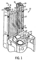
- Fig. 1 is a perspective view of a portion of a forklift truck employing the temperature control system of the preferred embodiment with a section of the operator console cut away;
- Fig. 2 is an electrical schematic diagram of a control circuit in accordance with a preferred embodiment of the invention.
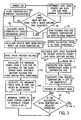
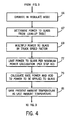
- Figs. 3 and 4 are a flow chart illustrating control of the heated glass guard.
- Fig. 5 is a graphic illustrating power provided to the glass versus ambient temperature.
- FIG. 1 a portion of an open forklift truck 10 is illustrated having an operator console 12 and a telescoping assembly 14 that supports the forklift (not shown).
- the telescoping assembly 14 includes a pair of elongated I-beams 16 that are supported in a vertical orientation by elongated beams 18 and 20.
- the forklift truck 10 operates under a plurality of controls located on the operator console 12, including a control handle 11, a steering column 13, and an array of switches.
- the control handle 11 provides an independent electrical position signal to control a respective one of the lift/lower, reach/retract, tilt and side shift functions of the forks by means of working hydraulics fitted to the truck, and controls the travel speed of the vehicle during forks first and forks trailing operations.
- a control handle 11 is illustrated in accordance with the preferred embodiment, it should be appreciated that any suitable alternative control apparatus could be used that is capable of producing a desired response.
- the use of a control handle 11 is preferred because it requires less operator effort than conventional hydraulic levers and facilitate longer working periods involving complex maneuvers without unduly tiring the operator.
- the steering column 13 controls the orientation of the forklift truck 10.
- the operator is typically positioned immediately behind the operator console 12, to allow for easy access to the controls, and between the I-beams 16, 18, 20 at various lifting stages to maximize his or her field of vision.
- the forklift truck 10 is, of course, mobile and suitable for use in cold storage applications typically having a temperature as low as -25°F or, in some cases, even lower.
- the truck 10 includes a windshield assembly 22 that is secured by a plurality of brackets 24 that are mounted onto the beams 20 in an overlapping relationship with the windshield assembly.
- the windshield assembly 22 has an extended height sufficient to significantly reduce the wind chill effect that is experienced by the operator during operation of the forklift truck 10 at high speeds in the cold storage environment.
- the windshield assembly 22 is preferably constructed of a laminate that includes first and second layers of tempered glass 28 and 26 having an inner surface 21 and an outer surface 23, respectively. Because the forklift truck 10 is an open vehicle, both surfaces 21 and 23 are exposed to the ambient environment and are capable of producing condensation when the truck 10 travels from the cold storage application to the warmer environment. Although tempered glass is described, it should be appreciated that the windshield assembly could comprise any alternative suitable material that is readily heated, and that is adequately transparent such that the operator's vision is unobstructed.
- a heating assembly 27 includes a plurality of thin elongated heating copper wires 25 that are sandwiched between the two layers of glass 26 and 28.
- the wires 25 extend vertically and are spaced equidistantly apart across the entire width of the windshield assembly 22.
- Each wire 25 is connected at its top end to a bus bar 29, formed from tinned copper foil, that extends across the top of the windshield assembly 22.
- a similar bus bar 31 that extends across the bottom of the windshield assembly 22 is connected to the wires 25 at their lower ends.
- the wires 25 and bus bars 29 and 31 may be formed from any suitable conductive material.
- the wires 25 are embedded within the windshield assembly 22, they are capable of maintaining the temperature of both surfaces 21 and 23 greater than the dew point of the warmer environment. Additionally, because the wires 25 are preferably disposed equidistantly between the inner and outer surfaces 21 and 23, equal amounts of heat are applied to each surface, thereby maintaining the surfaces at substantially the same temperature, further reducing the risk of condensation from accumulating on one of the surfaces. It should be appreciated that the wires 25 could alternatively extend horizontally in accordance with an alternate embodiment.
- the heating assembly 27 is placed between the tempered glass sections 26 and 28, which are adhesively attached to each other using an adhesive, such as PVB.
- an adhesive such as PVB.
- any alternative suitable windshield laminate having a heating assembly therein, and that is capable of maintaining the temperature of the inner and outer surfaces 21 and 23 greater than the dew point of the warmer environment may be used, as would be understood by one having ordinary skill in the art.
- the bus bars 29 and 31 form part of a control circuit 36 which conducts current to the heating wires 25.
- the current flow through the wires 25 produces heat proportional to the resistance and the square of the current (I 2 *R), and this heat is conducted relatively uniformly throughout the windshield assembly 22.
- the wires 25 are configured to supply heat to both layers 26 and 28 of the windshield assembly 22 to maintain the temperature of the inner surface 21 substantially the same as the temperature of the outer surface 23, thereby preventing condensation from accumulating on either surface of the assembly.
- the control circuit 36 includes a controller 44, which can be a microprocessor, microcontroller, or other device, including either an on-board or separate memory component 51, a real time clock 52, and circuitry for counting and accumulating pulses, shown here as pulse accumulator 54.
- the controller 44 drives a switching element 46, such as a drive transistor, that is coupled to the heating assembly 27 in the windshield assembly 22 to provide a switching power supply, and a contactor or relay 52 which provides power to and removes power from the heating assembly 27.
- the controller 44 receives feedback from a temperature sensor 40, a speed sensor 42, and voltage dividers 48 and 50, which are coupled to the battery 35 and the switching element 46, respectively.
- Material constants and other data related to the heating assembly 27 and windshield assembly 22 are stored in the memory 51 for use in calculating temperatures, as described below. These constants can include a maximum allowable heating temperature, which is based on the adhesive used to attach the heating assembly 27 to the windshield 22, and heating and resistance constants related to the wire in the heating assembly, including a heater wire resistance versus heater wire temperature and heater wire thermal resistance (temperature rise per unit power).
- material constants and other data related to the glass forming the windshield including glass surface thermal resistance (surface temperature rise per unit power applied), glass surface heating time constant, glass surface cooling time constant, and glass surface thermal loss versus truck speed, are stored in the memory 51. This stored data is retrieved from memory 51 and used in calculating the power applied to the windshield 22 as described below.
- the controller 44 receives a temperature feedback signal from the ambient temperature sensor 40, and a speed feedback signal from a traction speed indicator 42.
- Battery voltage feedback is sensed at the voltage divider 48, which is coupled to the battery 35 through a fuse 38.
- Application of power to the heating assembly 27 is similarly sensed at the voltage divider 50, which is coupled to the drain of drive transistor 46, and provides feedback indicating the number of pulses applied to the heating assembly 27 from the transistor 46.
- the controller 44 drives the drive transistor 46 using a pulse width modulated algorithm to provide power to the heater assembly 27. Two modes of operation are provided, a warm-up mode, which is entered when the forklift truck 10 is powered up; and a regulation mode, which is entered when the glass components of windshield assembly 22 reach a predetermined temperature, as described more fully below.
- a flow chart illustrating operation of the control circuit 36 is shown.
- the controller 44 calculates a time that the truck has been powered down or "off', and reads the ambient temperature (step 55).
- the controller 44 determines whether the "off" time exceeds four cooling time constants (step 56) based on timing data from the real time clock 52, and the cooling time constant that is retrieved from memory 51. If so, the temperature of the glass component of the windshield 22 is assumed to be the ambient temperature, as determined by feedback from the ambient temperature sensor 40 (step 58).
- the wire resistance thermal constant is given in ohms per degrees C.
- controller 44 reads the truck voltage from the battery (step 59), and calculates the maximum amount of power that can be safely applied to the heating assembly 27 (step 63), and the maximum power that can be applied based on the current voltage level of battery 35 (step 61), based on feedback sensed from the voltage divider 48.
- the heater wire thermal resistance is a material parameter given in degrees C per watt.
- the controller 44 compares the calculated temperature to a predetermined temperature level at which the temperature regulation mode is entered, which can be, for example, 100° F (step 64). If the calculated temperature is equivalent to the predetermined regulation temperature, the controller 44 enters the "regulate" mode (step 66).
- PWM duty cycle power to glass x heater wire resistance battery voltage 2 which is derived by combining the following formulas required
- step 78 the time and glass temperature values are saved in memory 51, and the controller 44 returns to step 57 to again calculate the heater wire resistance.
- the controller 44 when the calculated glass temperature exceeds the regulate threshold in step 64, the controller 44 does not enter the warm up mode in step 71, but instead enters the regulate mode 66.
- the power to be applied to the glass is determined by reference to a look-up table including empirical values relating applied power to the ambient temperature, as shown in Fig. 5 .
- This adjustment linearly adjusts the power applied to the glass from a 0% adjustment when the truck is not moving to a 30% boost of the power applied to the glass when the truck is moving at a speed of 7 miles per hour.
- the controller 44 compares the calculated power to the maximum value calculated in step 62 above, and applies the lower of the calculated value and the maximum value in step 77. In step 79, the controller 44 adjusts the power applied to the windshield to account for thermal time lags using a differentiator response.
- rate power temperature lag constant * d ambient temperature / dt
- the temperature lag constant is determined empirically, and is adjusted to minimize the windshield temperature variation when the vehicle is moved from one ambient temperature to another, such as when driving in and out of a freezer. Although this constant can vary somewhat depending on the vehicle used, in this application, the constant was calculated empirically to be substantially 200 watt-seconds per degrees C.
- step 57 power to glass * rate power
- the controller 44 monitors the transistor 46 by counting pulses from the voltage divider 50. No edges are counted if the drive transistor 46 has failed, either shorted or opened, if the heat system 25 fails, either shorted or opened, if the contactor 52 fails open, or if the fuse 38 fails open. Under these circumstances, the operator is alerted to the failure through either a visual or audio indicator and the maximum speed that the forklift truck is capable of reaching is reduced to minimize the effects of fogging on the windshield. To maintain efficiency of the vehicle, the reduction in speed can be applied only when the truck is moving in the forks first direction and the operator is facing the windshield.
Landscapes
- Engineering & Computer Science (AREA)
- Transportation (AREA)
- Mechanical Engineering (AREA)
- Structural Engineering (AREA)
- Power Engineering (AREA)
- Civil Engineering (AREA)
- Life Sciences & Earth Sciences (AREA)
- Geology (AREA)
- Forklifts And Lifting Vehicles (AREA)
Abstract
Description
- The present invention relates to forklift trucks, and in particular, relates to an improved method and apparatus for preventing fog and condensation from accumulating on a windshield of a forklift truck that traverses between environments having varying temperatures.
- When operating a forklift vehicle at higher speeds in cold storage environments, where temperatures can typically reach as low as -25°F, a significant wind chill is experienced by the operator, thereby causing discomfort. It is therefore desirable to install a windshield in the truck that will protect the operator from the winds associated with operation of the forklift truck in the cold environment and reduce operator discomfort.
- However, because forklift trucks typically traverse between cold storage applications and warm environments, the windshield may experience significant temperature differentials of more than 100° F. Moreover, due to the cold air flow within the cold storage application, various locations on the windshield may be colder than others. Additionally, because the temperature of the cold storage application is commonly less than the dew point of the warmer environment, condensation can accumulate on the windshield when the truck travels from the cold storage application into the warmer environment. Subsequently, when the truck travels back into the cold environment, the condensation can freeze on the windshield. The condensation and frozen condensation can obstruct the operator's view. Furthermore, frozen condensation can render the forklift truck unavailable for an extended amount of time.
- As a result of the significant drawbacks currently associated with installing a windshield on forklift trucks that traverse between environments having significantly varying temperatures, a wire mesh is conventionally used in place of a windshield so as to prevent condensation from obstructing the operator's view. However, the wire mesh inadequately shields the operator from the potentially severe wind chills that are produced during operation of the forklift truck.
- Because of these problems, heated windshield assemblies have also been constructed for use in forklift trucks operated in cold storage environments. These assemblies maintain appropriate temperature levels to reduce fogging and condensation from obstructing an operator's view, as discussed above, and have typically employed temperature sensors provided on the windshield to directly monitor the temperature. These heating devices, however, require additional components that add cost to the vehicle.
- The present invention provides a forklift or other material handling vehicle with a heated windshield for use in a cold storage environment. Environmental parameters, such as the ambient temperature of vehicle operation, and vehicle parameters, such as the speed of the vehicle and the battery voltage, are monitored using sensors in the vehicle and an on-board controller, and the feedback is used to adjust the power supply to the windshield in order to maintain the temperature at an appropriate level.
- In accordance with a first aspect of the invention, a man-operated vehicle of the type powered by a battery and including a traction motor configured to move the vehicle between a first location having a cold storage temperature, and a second location having a dew point temperature greater than the cold storage temperature, is provided. The vehicle comprises a windshield member having first and second surfaces exposed to the ambient environment. A heating assembly is disposed within the windshield member and configured to supply heat to the windshield. A control circuit is provided for supplying power to the heating assembly. The control circuit comprises a temperature sensor for sensing ambient temperatures, a speed sensor for sensing a speed of the man-operated vehicle, and a power regulator connected to the heating assembly. A controller is in electrical communication with the heating assembly, the temperature sensor and the speed sensor, and is operable to drive the power regulator to maintain the windshield at a predetermined temperature and to adjust the power supply to the heating assembly from the power regulator based on at least one of a rate of the sensed ambient temperature, the sensed speed of the man-operated vehicle, and a voltage level of the battery.
- In another aspect, a method for heating a windshield in an open, man operated, vehicle to prevent condensation from accumulating on the windshield as it travels between a cold location and a warm location is provided. The steps of the method include sensing an ambient temperature, calculating a temperature of the windshield, and applying electrical power to a heating assembly in the windshield to heat the windshield to a predetermined regulation temperature. The power supplied to the windshield is adjusted based on at least one of a speed of the vehicle and a rate of change of the ambient temperature while the vehicle is in operation.
- In still another aspect of the invention, a forklift vehicle is provided including a battery, a traction motor powered by the battery and configured to move the vehicle between a first location having a cold storage temperature, and a second location having a dew point temperature greater than the cold storage temperature, an operator compartment coupled to the traction motor and allowing an operator to ride in the vehicle, and a windshield member coupled to said operator compartment and having first and second surfaces exposed to the ambient environment. The first surface of the windshield faces the operator compartment, and the second surface faces away from the operator compartment. A heating assembly is disposed within the windshield member and configured to supply heat thereto, and a control circuit is provided for supplying power to the heating assembly.
- The control circuit comprises a temperature sensor for sensing ambient temperatures, a speed sensor for sensing a speed of the man-operated vehicle, a voltage sensor for sensing a voltage of the battery, and a switching element for providing a switched power supply to the heating assembly. A controller is in electrical communication with the heating elements, the temperature sensor and the speed sensor, and is operable to drive the switching element at a switching rate selected to supply electrical power to the heating assembly to heat the windshield to a predetermined temperature and to adjust the switching rate based on at least one of a sensed voltage level of the battery, a sensed ambient temperature and a sensed speed of the man-operated vehicle.
- These as well as other features and characteristics of the present invention will be apparent from the description which follows. In the detailed description below, preferred embodiments of the invention will be described with reference to the accompanying drawings. These embodiments do not represent the full scope of the invention. Rather the invention may be employed in other embodiments, and reference should therefore be made to the claims herein for interpreting the breadth of the invention.
- Reference is hereby made to the following figures in which like reference numerals correspond to like elements throughout and in which:
-
Fig. 1 is a perspective view of a portion of a forklift truck employing the temperature control system of the preferred embodiment with a section of the operator console cut away; and -
Fig. 2 is an electrical schematic diagram of a control circuit in accordance with a preferred embodiment of the invention. -
Figs. 3 and4 are a flow chart illustrating control of the heated glass guard. -
Fig. 5 is a graphic illustrating power provided to the glass versus ambient temperature. - Referring initially to
Fig. 1 , a portion of anopen forklift truck 10 is illustrated having anoperator console 12 and atelescoping assembly 14 that supports the forklift (not shown). Thetelescoping assembly 14 includes a pair of elongated I-beams 16 that are supported in a vertical orientation byelongated beams - The
forklift truck 10 operates under a plurality of controls located on theoperator console 12, including acontrol handle 11, asteering column 13, and an array of switches. Thecontrol handle 11 provides an independent electrical position signal to control a respective one of the lift/lower, reach/retract, tilt and side shift functions of the forks by means of working hydraulics fitted to the truck, and controls the travel speed of the vehicle during forks first and forks trailing operations. Although acontrol handle 11 is illustrated in accordance with the preferred embodiment, it should be appreciated that any suitable alternative control apparatus could be used that is capable of producing a desired response. The use of acontrol handle 11 is preferred because it requires less operator effort than conventional hydraulic levers and facilitate longer working periods involving complex maneuvers without unduly tiring the operator. - Referring still to
Fig. 1 , thesteering column 13 controls the orientation of theforklift truck 10. During operation of thetruck 10, the operator is typically positioned immediately behind theoperator console 12, to allow for easy access to the controls, and between the I-beams forklift truck 10 is, of course, mobile and suitable for use in cold storage applications typically having a temperature as low as -25°F or, in some cases, even lower. - The
truck 10 includes awindshield assembly 22 that is secured by a plurality ofbrackets 24 that are mounted onto thebeams 20 in an overlapping relationship with the windshield assembly. Thewindshield assembly 22 has an extended height sufficient to significantly reduce the wind chill effect that is experienced by the operator during operation of theforklift truck 10 at high speeds in the cold storage environment. - The
windshield assembly 22 is preferably constructed of a laminate that includes first and second layers of tempered glass 28 and 26 having an inner surface 21 and an outer surface 23, respectively. Because theforklift truck 10 is an open vehicle, both surfaces 21 and 23 are exposed to the ambient environment and are capable of producing condensation when thetruck 10 travels from the cold storage application to the warmer environment. Although tempered glass is described, it should be appreciated that the windshield assembly could comprise any alternative suitable material that is readily heated, and that is adequately transparent such that the operator's vision is unobstructed. - As shown in
Fig. 1 , aheating assembly 27 includes a plurality of thin elongatedheating copper wires 25 that are sandwiched between the two layers of glass 26 and 28. Thewires 25 extend vertically and are spaced equidistantly apart across the entire width of thewindshield assembly 22. Eachwire 25 is connected at its top end to abus bar 29, formed from tinned copper foil, that extends across the top of thewindshield assembly 22. Asimilar bus bar 31 that extends across the bottom of thewindshield assembly 22 is connected to thewires 25 at their lower ends. Thewires 25 andbus bars wires 25 are embedded within thewindshield assembly 22, they are capable of maintaining the temperature of both surfaces 21 and 23 greater than the dew point of the warmer environment. Additionally, because thewires 25 are preferably disposed equidistantly between the inner and outer surfaces 21 and 23, equal amounts of heat are applied to each surface, thereby maintaining the surfaces at substantially the same temperature, further reducing the risk of condensation from accumulating on one of the surfaces. It should be appreciated that thewires 25 could alternatively extend horizontally in accordance with an alternate embodiment. - In accordance with the preferred embodiment, the
heating assembly 27 is placed between the tempered glass sections 26 and 28, which are adhesively attached to each other using an adhesive, such as PVB. It should be appreciated, however, that any alternative suitable windshield laminate having a heating assembly therein, and that is capable of maintaining the temperature of the inner and outer surfaces 21 and 23 greater than the dew point of the warmer environment may be used, as would be understood by one having ordinary skill in the art. - As will be described in more detail below, the bus bars 29 and 31 form part of a control circuit 36 which conducts current to the
heating wires 25. As is well known in the art, the current flow through thewires 25 produces heat proportional to the resistance and the square of the current (I2*R), and this heat is conducted relatively uniformly throughout thewindshield assembly 22. As a result, thewires 25 are configured to supply heat to both layers 26 and 28 of thewindshield assembly 22 to maintain the temperature of the inner surface 21 substantially the same as the temperature of the outer surface 23, thereby preventing condensation from accumulating on either surface of the assembly. - Referring now also to
Fig. 2 , a control circuit 36 for controlling the heating of the tempered glass of thewindshield assembly 22 is schematically illustrated. The control circuit 36 includes acontroller 44, which can be a microprocessor, microcontroller, or other device, including either an on-board orseparate memory component 51, areal time clock 52, and circuitry for counting and accumulating pulses, shown here aspulse accumulator 54. Thecontroller 44 drives a switchingelement 46, such as a drive transistor, that is coupled to theheating assembly 27 in thewindshield assembly 22 to provide a switching power supply, and a contactor or relay 52 which provides power to and removes power from theheating assembly 27. Thecontroller 44 receives feedback from atemperature sensor 40, aspeed sensor 42, andvoltage dividers battery 35 and the switchingelement 46, respectively. Material constants and other data related to theheating assembly 27 andwindshield assembly 22 are stored in thememory 51 for use in calculating temperatures, as described below. These constants can include a maximum allowable heating temperature, which is based on the adhesive used to attach theheating assembly 27 to thewindshield 22, and heating and resistance constants related to the wire in the heating assembly, including a heater wire resistance versus heater wire temperature and heater wire thermal resistance (temperature rise per unit power). Additionally, material constants and other data related to the glass forming the windshield, including glass surface thermal resistance (surface temperature rise per unit power applied), glass surface heating time constant, glass surface cooling time constant, and glass surface thermal loss versus truck speed, are stored in thememory 51. This stored data is retrieved frommemory 51 and used in calculating the power applied to thewindshield 22 as described below. - In operation, the
controller 44 receives a temperature feedback signal from theambient temperature sensor 40, and a speed feedback signal from atraction speed indicator 42. Battery voltage feedback is sensed at thevoltage divider 48, which is coupled to thebattery 35 through afuse 38. Application of power to theheating assembly 27 is similarly sensed at thevoltage divider 50, which is coupled to the drain ofdrive transistor 46, and provides feedback indicating the number of pulses applied to theheating assembly 27 from thetransistor 46. Based on the feedback, thecontroller 44 drives thedrive transistor 46 using a pulse width modulated algorithm to provide power to theheater assembly 27. Two modes of operation are provided, a warm-up mode, which is entered when theforklift truck 10 is powered up; and a regulation mode, which is entered when the glass components ofwindshield assembly 22 reach a predetermined temperature, as described more fully below. - Referring now to
Figs. 3 and4 , a flow chart illustrating operation of the control circuit 36 is shown. Initially, when power is turned on, thecontroller 44 calculates a time that the truck has been powered down or "off', and reads the ambient temperature (step 55). Thecontroller 44 then determines whether the "off" time exceeds four cooling time constants (step 56) based on timing data from thereal time clock 52, and the cooling time constant that is retrieved frommemory 51. If so, the temperature of the glass component of thewindshield 22 is assumed to be the ambient temperature, as determined by feedback from the ambient temperature sensor 40 (step 58). If not,controller 44 calculates the temperature of the glass using the following formula (step 60):
Here, the last glass temperature can, again, be retrieved frommemory 51. After the glass temperature is determined, thecontroller 44 calculates the heater wire resistance (step 57), using the following equation:
Here, the wire resistance thermal constant is given in ohms per degrees C. After the heater wire resistance is calculated,controller 44 reads the truck voltage from the battery (step 59), and calculates the maximum amount of power that can be safely applied to the heating assembly 27 (step 63), and the maximum power that can be applied based on the current voltage level of battery 35 (step 61), based on feedback sensed from thevoltage divider 48. The maximum power which can be safely applied to thewindshield 22 is given by the following equation:
Here, the heater wire thermal resistance is a material parameter given in degrees C per watt. The maximum power which can be applied given the present voltage ofbattery 35 is given by the following equation:
After these values are calculated, thecontroller 44 selects the lower of the of the two maximum power calculations (step 62), to be used in further calculations below. - The
controller 44 then compares the calculated temperature to a predetermined temperature level at which the temperature regulation mode is entered, which can be, for example, 100° F (step 64). If the calculated temperature is equivalent to the predetermined regulation temperature, thecontroller 44 enters the "regulate" mode (step 66). If not, thecontroller 44 continues to regulate thewindshield 22 in the "warm up" mode (step 71), applying the selected maximum power level to theheating assembly 27 by controlling thetransistor 46, and, instep 73, calculating the glass temperature using the following equations:

where the final glass temperature is the temperature that the windshield temperature would rise to if the heater was left on indefinitely, and where the glass surface thermal resistance is a material constant in degrees C per watt. - After the temperature is calculated, the
controller 44 then calculates the pulse width modulated (PWM) duty cycle for driving thetransistor 46 based on the selected value using the following equation:
which is derived by combining the following formulas
and
After the PWM duty cycle is calculated instep 74, the controller adjusts commands to thetransistor 46 to drive the transistor at the calculated duty cycle instep 76. Instep 78, the time and glass temperature values are saved inmemory 51, and thecontroller 44 returns to step 57 to again calculate the heater wire resistance. - Referring now to
Fig. 4 , when the calculated glass temperature exceeds the regulate threshold instep 64, thecontroller 44 does not enter the warm up mode instep 71, but instead enters the regulatemode 66. In the regulatemode 66, the power to be applied to the glass is determined by reference to a look-up table including empirical values relating applied power to the ambient temperature, as shown inFig. 5 . The value retrieved from the table is then multiplied by a truck speed factor instep 69, as follows:
where the Truck Speed Factor is calculated as:
- This adjustment linearly adjusts the power applied to the glass from a 0% adjustment when the truck is not moving to a 30% boost of the power applied to the glass when the truck is moving at a speed of 7 miles per hour. The
controller 44 compares the calculated power to the maximum value calculated instep 62 above, and applies the lower of the calculated value and the maximum value instep 77. Instep 79, thecontroller 44 adjusts the power applied to the windshield to account for thermal time lags using a differentiator response. A "rate power" term is first calculated by taking the derivative of the ambient temperature with respect to time and multiplying it by a scaling constant:
When using a digital controller, the derivative is computed using the presently measured ambient temperatures as well as a previously measured ambient temperature taken at a known time interval. The temperature lag constant is determined empirically, and is adjusted to minimize the windshield temperature variation when the vehicle is moved from one ambient temperature to another, such as when driving in and out of a freezer. Although this constant can vary somewhat depending on the vehicle used, in this application, the constant was calculated empirically to be substantially 200 watt-seconds per degrees C.
The rate power term is then added to the previously calculated value of power to be applied to the windshield to get the final amount of power to be applied to the windshield:
After the appropriate power level is calculated, the present ambient temperature is saved for reference in the next loop of control, and thecontroller 44 advances to step 74 (Fig. 3 ), described above. The controller then returns to step 57 (Fig. 3 ). The loop betweenstep 57 andstep 78 continues as long as the power to the truck stays on. - As power is applied, the
controller 44 monitors thetransistor 46 by counting pulses from thevoltage divider 50. No edges are counted if thedrive transistor 46 has failed, either shorted or opened, if theheat system 25 fails, either shorted or opened, if thecontactor 52 fails open, or if thefuse 38 fails open. Under these circumstances, the operator is alerted to the failure through either a visual or audio indicator and the maximum speed that the forklift truck is capable of reaching is reduced to minimize the effects of fogging on the windshield. To maintain efficiency of the vehicle, the reduction in speed can be applied only when the truck is moving in the forks first direction and the operator is facing the windshield. - The above has been described as a preferred embodiment of the present invention. It will occur to those that practice the art that many modifications may be made without departing from the spirit and scope of the invention. In order to apprise the public of the various embodiments that may fall within the scope of the invention, the following claims are made.
Claims (13)
- A man-operated material handling vehicle of the type powered by a battery and including a traction motor configured to move the vehicle between a first location having a cold storage temperature, and a second location having a dew point temperature greater than the cold storage temperature, the vehicle comprising:a windshield member mounted onto said vehicle having first and second surfaces exposed to the ambient environment, wherein the first surface faces an operator console, and the second surface faces away from the operator console;a heating assembly disposed within the windshield member and configured to supply heat thereto; anda control circuit for supplying power to the heating assembly, the control circuit comprising:a temperature sensor for sensing ambient temperatures;a speed sensor for sensing a speed of the man-operated vehicle;a power regulator connected to the heating assembly; anda controller in electrical communication with the heating assembly, the temperature sensor and the speed sensor, the controller being operable to drive the power regulator to maintain the windshield at a predetermined temperature and to adjust the power supply to the heating assembly from the power regulator based on at least one of a rate of the sensed ambient temperature, the sensed speed of the man-operated vehicle, and a voltage level of the battery.
- The vehicle as recited in claim 1, wherein the controller is further operable to calculate a maximum power level that can be applied to the windshield, and a necessary power level to maintain the windshield at the predetermined temperature at the sensed ambient temperature and the sensed truck speed, and to control the power regulator to deliver power at the lower of the maximum power level and the necessary power level.
- The vehicle as recited in claim 2, wherein the controller is further operable to calculate a maximum power level that can be applied at the sensed battery voltage level, and to deliver power at the lower of the maximum power level, the necessary power level, and the maximum power level at the sensed battery voltage.
- The vehicle as recited in claim 1, wherein the power regulator comprises a switching element, and the controller is further operable to drive the switching element at a pulse width modulated duty cycle.
- The vehicle as recited in claim 4, wherein the controller is further operable to calculate a pulse width modulated duty cycle using the following equation:

- The vehicle as recited in claim 1, wherein the controller is further operable to calculate a surface temperature of the windshield when power is initially applied based on a temperature at power off, an ambient temperature, and a cooling time constant of the windshield material.
- The vehicle as recited in claim 6, wherein the controller is further operable to calculate a temperature of the windshield during a warm-up period as a function of the following equation:

- The vehicle as recited in claim 1, wherein the vehicle is an open forklift truck.
- The vehicle as recited in claim 1, wherein the controller adjusts the power supply based on a rate of change of the ambient temperature and the truck speed.
- The method as recited in claim 6, wherein the controller is further operable to calculate the temperature of the windshield using the following equation:

- The method as recited in claim 6, wherein the controller is operable to determine whether the vehicle has been off for a period of four or more cooling time constants and to assign the ambient temperature as the temperature of the windshield when the vehicle has been off for more than four time constants.
- The vehicle of claim 1, wherein the power regulator comprises a switching element, and the controller is operable to adjust the switching rate based on the rate of change of the sensed ambient temperature.
- The vehicle of claim 1, wherein the power regulator comprises a switching element and the controller is operable to calculate a maximum power level and to drive the switching element based on the maximum power level.
Applications Claiming Priority (1)
| Application Number | Priority Date | Filing Date | Title |
|---|---|---|---|
| US11/763,953 US8084716B2 (en) | 2007-06-15 | 2007-06-15 | Heated glass guard with sensorless control for forklift trucks |
Publications (1)
| Publication Number | Publication Date |
|---|---|
| EP2014604A1 true EP2014604A1 (en) | 2009-01-14 |
Family
ID=39745481
Family Applications (1)
| Application Number | Title | Priority Date | Filing Date |
|---|---|---|---|
| EP08010518A Withdrawn EP2014604A1 (en) | 2007-06-15 | 2008-06-10 | Heated sensorless glass guard with control for forklift trucks |
Country Status (3)
| Country | Link |
|---|---|
| US (1) | US8084716B2 (en) |
| EP (1) | EP2014604A1 (en) |
| CA (1) | CA2635084C (en) |
Cited By (1)
| Publication number | Priority date | Publication date | Assignee | Title |
|---|---|---|---|---|
| WO2023099919A1 (en) * | 2021-12-03 | 2023-06-08 | Diamond Coatings Ltd | Resistive heating device |
Families Citing this family (8)
| Publication number | Priority date | Publication date | Assignee | Title |
|---|---|---|---|---|
| DE102011009672A1 (en) * | 2011-01-28 | 2012-08-02 | Webasto Ag | Electric heating, vehicle with electric heating and method of controlling an electric heater |
| US9045043B2 (en) | 2013-01-23 | 2015-06-02 | Ford Global Technologies, Llc | Zonal vehicle glass heating strategy |
| US9371217B1 (en) * | 2013-05-09 | 2016-06-21 | Mark C. DePumpo | Large wheeled, hand operated forklift |
| US10067006B2 (en) | 2014-06-19 | 2018-09-04 | Elwha Llc | Nanostructure sensors and sensing systems |
| US10285220B2 (en) | 2014-10-24 | 2019-05-07 | Elwha Llc | Nanostructure heaters and heating systems and methods of fabricating the same |
| US10785832B2 (en) * | 2014-10-31 | 2020-09-22 | Elwha Llc | Systems and methods for selective sensing and selective thermal heating using nanostructures |
| WO2016160113A2 (en) * | 2015-03-31 | 2016-10-06 | Crown Equipment Corporation | Method for controlling a functional system of a materials handling vehicle |
| JP7852562B2 (en) * | 2023-04-24 | 2026-04-28 | トヨタ自動車株式会社 | Defogger control unit |
Citations (6)
| Publication number | Priority date | Publication date | Assignee | Title |
|---|---|---|---|---|
| EP0991301A1 (en) * | 1998-09-30 | 2000-04-05 | Volkswagen Aktiengesellschaft | Window heating device for vehicles |
| WO2001039549A1 (en) * | 1999-11-26 | 2001-05-31 | Tyco Electronics Raychem Gmbh | Control of heating arrangement with multiple sensors |
| DE10042563A1 (en) * | 2000-08-30 | 2002-03-28 | Audi Ag | Control method for heating of automobile external rear view mirror regulates heating power dependent on vehicle velocity and external temperature |
| EP1234736A1 (en) * | 2001-02-05 | 2002-08-28 | The Raymond Corporation | Heated windscreen for forklift trucks |
| EP1318697A1 (en) * | 2001-12-07 | 2003-06-11 | Delphi Technologies, Inc. | Power control method for a motor vehicle electric window heater |
| DE102005055003A1 (en) * | 2005-11-18 | 2007-05-24 | Bayerische Motoren Werke Ag | Wind defogger`s power controlling method for window pane, involves determining actual temperature of window pane depending on environmental and vehicle parameters, and adjusting defogger power depending on actual and reference temperatures |
Family Cites Families (11)
| Publication number | Priority date | Publication date | Assignee | Title |
|---|---|---|---|---|
| US2979596A (en) * | 1961-04-11 | Windshield temperature controller | ||
| EP0008929A1 (en) * | 1978-09-05 | 1980-03-19 | John Walter Rilett | Motors and gas supply apparatus therefor |
| US4277672A (en) | 1979-12-03 | 1981-07-07 | General Electric Company | Control circuit for controlling quantity of heat to electrically heatable windshield |
| JP2501334B2 (en) * | 1987-06-19 | 1996-05-29 | 松下電工株式会社 | Reflow furnace |
| CA2049452A1 (en) * | 1990-08-21 | 1992-02-22 | Sheng-Hann Lee | Window cleaning fluid heating system |
| US6163013A (en) | 1992-12-07 | 2000-12-19 | Navistar International Transportation Corp | Continuous duty direct current heated windshield with ambient temperature limit switch |
| US5496989A (en) * | 1994-05-05 | 1996-03-05 | United Technology Corporation | Windshield temperature control system |
| US5632917A (en) | 1994-08-08 | 1997-05-27 | Ford Motor Company | Electric windshield defroster |
| US6037573A (en) | 1998-05-15 | 2000-03-14 | Ford Motor Company | System and method for controlling the operation of a heated wiper area |
| DE10120098B4 (en) * | 2001-04-25 | 2004-02-05 | Brose Fahrzeugteile Gmbh & Co. Kg | Heating and method for controlling the heating of a functional unit of a motor vehicle |
| US6624396B2 (en) * | 2001-08-28 | 2003-09-23 | Hatco Corporation | Conveyor speed control system for a conveyor oven |
-
2007
- 2007-06-15 US US11/763,953 patent/US8084716B2/en active Active
-
2008
- 2008-06-10 EP EP08010518A patent/EP2014604A1/en not_active Withdrawn
- 2008-06-13 CA CA2635084A patent/CA2635084C/en active Active
Patent Citations (6)
| Publication number | Priority date | Publication date | Assignee | Title |
|---|---|---|---|---|
| EP0991301A1 (en) * | 1998-09-30 | 2000-04-05 | Volkswagen Aktiengesellschaft | Window heating device for vehicles |
| WO2001039549A1 (en) * | 1999-11-26 | 2001-05-31 | Tyco Electronics Raychem Gmbh | Control of heating arrangement with multiple sensors |
| DE10042563A1 (en) * | 2000-08-30 | 2002-03-28 | Audi Ag | Control method for heating of automobile external rear view mirror regulates heating power dependent on vehicle velocity and external temperature |
| EP1234736A1 (en) * | 2001-02-05 | 2002-08-28 | The Raymond Corporation | Heated windscreen for forklift trucks |
| EP1318697A1 (en) * | 2001-12-07 | 2003-06-11 | Delphi Technologies, Inc. | Power control method for a motor vehicle electric window heater |
| DE102005055003A1 (en) * | 2005-11-18 | 2007-05-24 | Bayerische Motoren Werke Ag | Wind defogger`s power controlling method for window pane, involves determining actual temperature of window pane depending on environmental and vehicle parameters, and adjusting defogger power depending on actual and reference temperatures |
Cited By (1)
| Publication number | Priority date | Publication date | Assignee | Title |
|---|---|---|---|---|
| WO2023099919A1 (en) * | 2021-12-03 | 2023-06-08 | Diamond Coatings Ltd | Resistive heating device |
Also Published As
| Publication number | Publication date |
|---|---|
| CA2635084C (en) | 2016-07-19 |
| CA2635084A1 (en) | 2008-12-15 |
| US8084716B2 (en) | 2011-12-27 |
| US20080308542A1 (en) | 2008-12-18 |
Similar Documents
| Publication | Publication Date | Title |
|---|---|---|
| US8084716B2 (en) | Heated glass guard with sensorless control for forklift trucks | |
| EP0726632B1 (en) | Lift truck with internal temperature monitor and system | |
| CA1158813A (en) | Anti-freezing system for a windshield-wiper | |
| US6507164B1 (en) | Current based power management for a trolling motor | |
| EP2082920B1 (en) | Electric additional heating for a motor vehicle | |
| EP2801248B1 (en) | End of cut speed control system | |
| EP1477386B1 (en) | Electric motor drive apparatus and motor-driven power steering system | |
| JP3687212B2 (en) | Battery cooling system | |
| US7828036B2 (en) | Wind sensing awning control having arm-mounted sensor | |
| EP0468806B1 (en) | Temperature control system for motors and power components of a material handling vehicle | |
| US20090240312A1 (en) | Patient Temperature Control System With Variable Gradient Warming/Cooling | |
| US20040075411A1 (en) | Wind sensing awning control | |
| EP1876511A2 (en) | Method and system for supplying electrical energy from a battery power supply unit | |
| EP1318697A1 (en) | Power control method for a motor vehicle electric window heater | |
| CA2819790A1 (en) | Switched reluctance motor torque estimation | |
| JP2020108213A (en) | Electric work vehicle | |
| HK1128914A (en) | Heated sensorless glass guard with control for forklift trucks | |
| EP1234736B1 (en) | Vehicle with heated windscreen | |
| CA3194388A1 (en) | Power indicator for electric vehicle | |
| DE10058434A1 (en) | Controlling a heater for an external mirror on a vehicle controls heating power for the heater by relying on a change in external temperature per unit of time | |
| EP1475263B1 (en) | A controller for a power train | |
| CN212709149U (en) | Automatic cover heat preservation device and transport vechicle | |
| DE10042563A1 (en) | Control method for heating of automobile external rear view mirror regulates heating power dependent on vehicle velocity and external temperature | |
| JP3436665B2 (en) | Electric vehicle speed control device | |
| WO2015200136A1 (en) | Engine cooling dual fan system with ec and dc motors and method of operating |
Legal Events
| Date | Code | Title | Description |
|---|---|---|---|
| PUAI | Public reference made under article 153(3) epc to a published international application that has entered the european phase |
Free format text: ORIGINAL CODE: 0009012 |
|
| PUAI | Public reference made under article 153(3) epc to a published international application that has entered the european phase |
Free format text: ORIGINAL CODE: 0009012 |
|
| AK | Designated contracting states |
Kind code of ref document: A1 Designated state(s): AT BE BG CH CY CZ DE DK EE ES FI FR GB GR HR HU IE IS IT LI LT LU LV MC MT NL NO PL PT RO SE SI SK TR |
|
| AX | Request for extension of the european patent |
Extension state: AL BA MK RS |
|
| 17P | Request for examination filed |
Effective date: 20090126 |
|
| AKX | Designation fees paid |
Designated state(s): DE FR GB IT SE |
|
| REG | Reference to a national code |
Ref country code: HK Ref legal event code: DE Ref document number: 1128914 Country of ref document: HK |
|
| 17Q | First examination report despatched |
Effective date: 20100115 |
|
| STAA | Information on the status of an ep patent application or granted ep patent |
Free format text: STATUS: THE APPLICATION IS DEEMED TO BE WITHDRAWN |
|
| 18D | Application deemed to be withdrawn |
Effective date: 20101231 |
|
| REG | Reference to a national code |
Ref country code: HK Ref legal event code: WD Ref document number: 1128914 Country of ref document: HK |