EP2014377A1 - Mounting for turbine blades - Google Patents
Mounting for turbine blades Download PDFInfo
- Publication number
- EP2014377A1 EP2014377A1 EP07013720A EP07013720A EP2014377A1 EP 2014377 A1 EP2014377 A1 EP 2014377A1 EP 07013720 A EP07013720 A EP 07013720A EP 07013720 A EP07013720 A EP 07013720A EP 2014377 A1 EP2014377 A1 EP 2014377A1
- Authority
- EP
- European Patent Office
- Prior art keywords
- blade
- holder
- clamping devices
- linkage
- turbine blades
- Prior art date
- Legal status (The legal status is an assumption and is not a legal conclusion. Google has not performed a legal analysis and makes no representation as to the accuracy of the status listed.)
- Granted
Links
Images


Classifications
-
- C—CHEMISTRY; METALLURGY
- C23—COATING METALLIC MATERIAL; COATING MATERIAL WITH METALLIC MATERIAL; CHEMICAL SURFACE TREATMENT; DIFFUSION TREATMENT OF METALLIC MATERIAL; COATING BY VACUUM EVAPORATION, BY SPUTTERING, BY ION IMPLANTATION OR BY CHEMICAL VAPOUR DEPOSITION, IN GENERAL; INHIBITING CORROSION OF METALLIC MATERIAL OR INCRUSTATION IN GENERAL
- C23C—COATING METALLIC MATERIAL; COATING MATERIAL WITH METALLIC MATERIAL; SURFACE TREATMENT OF METALLIC MATERIAL BY DIFFUSION INTO THE SURFACE, BY CHEMICAL CONVERSION OR SUBSTITUTION; COATING BY VACUUM EVAPORATION, BY SPUTTERING, BY ION IMPLANTATION OR BY CHEMICAL VAPOUR DEPOSITION, IN GENERAL
- C23C14/00—Coating by vacuum evaporation, by sputtering or by ion implantation of the coating forming material
- C23C14/22—Coating by vacuum evaporation, by sputtering or by ion implantation of the coating forming material characterised by the process of coating
- C23C14/50—Substrate holders
- C23C14/505—Substrate holders for rotation of the substrates
-
- C—CHEMISTRY; METALLURGY
- C23—COATING METALLIC MATERIAL; COATING MATERIAL WITH METALLIC MATERIAL; CHEMICAL SURFACE TREATMENT; DIFFUSION TREATMENT OF METALLIC MATERIAL; COATING BY VACUUM EVAPORATION, BY SPUTTERING, BY ION IMPLANTATION OR BY CHEMICAL VAPOUR DEPOSITION, IN GENERAL; INHIBITING CORROSION OF METALLIC MATERIAL OR INCRUSTATION IN GENERAL
- C23C—COATING METALLIC MATERIAL; COATING MATERIAL WITH METALLIC MATERIAL; SURFACE TREATMENT OF METALLIC MATERIAL BY DIFFUSION INTO THE SURFACE, BY CHEMICAL CONVERSION OR SUBSTITUTION; COATING BY VACUUM EVAPORATION, BY SPUTTERING, BY ION IMPLANTATION OR BY CHEMICAL VAPOUR DEPOSITION, IN GENERAL
- C23C14/00—Coating by vacuum evaporation, by sputtering or by ion implantation of the coating forming material
- C23C14/04—Coating on selected surface areas, e.g. using masks
- C23C14/042—Coating on selected surface areas, e.g. using masks using masks
Definitions
- the invention relates to a holder for at least two turbine blades for use in a coating device, which has a clamping device for fixing the blade root and blade for each turbine blade, wherein at least two clamping devices are mounted one above the other on a rod of the holder.
- Turbine blades are provided with coatings to increase their heat and corrosion resistance.
- an MCrAlY adhesion promoter layer and a ceramic layer thereon are applied by PVD (Physical Vapor Deposition).
- PVD Physical Vapor Deposition
- brackets are known to fix a plurality of turbine blades simultaneously, which can then be arranged as a whole in a coating chamber. The use of such holders makes it possible to coat a plurality of turbine blades in one pass.
- a holder of the type mentioned is, for example, in the EP 0 975 435 B1 described.
- This holder comprises a central element on which clamping devices for turbine blades are formed on several levels one above the other.
- the clamping devices are designed in each case to fix a turbine blade to its blade root and to its blade leaf. Furthermore, in each case two clamping devices are arranged in superimposed planes mirror images of each other.
- the clamping devices are each provided with a masking element, which encloses the blade root in the clamped state.
- This masking element may be, for example, box-shaped and have open upper and lower sides.
- the turbine blade can then be guided with its blade root through the open top. Subsequently, the underside of the masking element is closed, so that the blade root of the turbine blade is completely surrounded by the masking element.
- Advantages of this embodiment are that it can be prevented in a simple manner that coating material reaches the surface of the blade root.
- clamping devices each have a shading element for the trailing edge of the airfoil. This will ensure that no coating material impinges on the trailing edge of the blade during the coating process.
- the linkage has a central element over which the holder is rotatable as a whole. This design makes it possible to rotate the coating device during the coating process so that the clamped turbine blades are uniformly coated from all sides.
- FIG. 1 a holder for six turbine blades according to the invention is shown in a perspective view, which is designed for use in a coating apparatus.
- the holder has six clamping devices 1, wherein in each case three clamping devices are mounted on a plane via star-shaped holding elements 2 on a linkage 3 of the holder. In each case two clamping devices 1 of the various levels are arranged one above the other with the same orientation in alignment.
- the clamping devices 1 each have a lower, not shown in the drawing clamping element for fixing a blade root and an upper clamping element 4 for fixing a blade of a turbine blade, which are each attached to two superposed holding elements 2. Furthermore, the clamping devices 1 are each provided with a box-shaped masking element 5 for the blade root of the turbine blade.
- the masking element 5 has an open top 6 and an open bottom, wherein the top 6 is formed to enclose a performed airfoil. At the open bottom, a closure flap, not shown in the drawing, can be attached, which closes the masking element 5 after insertion of the turbine blade, so that the blade root of the turbine blade is completely enclosed by the masking element 5.
- the linkage 3 of the holder is formed by a column-shaped central element 8, the holding elements 2 and stiffening rods 9, which connect the superposed holding elements 2 together.
- the central element 8 of the linkage 3 is designed so that it can be rotated automatically about its own axis, for example, after connection with a suitable motor.
- the entire rod 3 is designed to be dismantled.
- the middle holding element 2b is pushed onto the central element 8 of the holder until the upper clamping elements 4 formed on the underside of the holding element 2b surround the tips of the blades of the turbine blade 10.
- the shutdown elements 7 cover the trailing edges of the blades.
- the blades are fixed by means of the upper clamping elements 4.
- the holder is shown in this state, but only a turbine blade 10 is fixed.
- FIG. 5 shows the holder with an inserted turbine blade 10 with all three retaining elements 2a, 2b, 2c, but without the stiffening rods.
- the bracket may be used with the turbine blade 10 in a coating apparatus.
Abstract
Description
Die Erfindung betrifft eine Halterung für wenigstens zwei Turbinenschaufeln zur Verwendung in einer Beschichtungsvorrichtung, die für jede Turbinenschaufel eine Einspanneinrichtung zur Fixierung von Schaufelfuß und Schaufelblatt aufweist, wobei wenigstens zwei Einspanneinrichtungen übereinander an einem Gestänge der Halterung angebracht sind.The invention relates to a holder for at least two turbine blades for use in a coating device, which has a clamping device for fixing the blade root and blade for each turbine blade, wherein at least two clamping devices are mounted one above the other on a rod of the holder.
Turbinenschaufeln werden mit Beschichtungen versehen, um ihre Wärme- und Korrosionsbeständigkeit zu erhöhen. Dazu werden beispielsweise eine MCrAlY-Haftvermittlerschicht und eine darauf liegende Keramikschicht durch PVD (Physical Vapour Deposition) aufgetragen. Im Stand der Technik sind Halterungen bekannt, um mehrere Turbinenschaufeln gleichzeitig zu fixieren, die dann als Ganzes in einer Beschichtungskammer angeordnet werden können. Der Einsatz derartiger Halterungen ermöglicht es, mehrere Turbinenschaufeln in einem Durchgang zu beschichten.Turbine blades are provided with coatings to increase their heat and corrosion resistance. For this purpose, for example, an MCrAlY adhesion promoter layer and a ceramic layer thereon are applied by PVD (Physical Vapor Deposition). In the prior art brackets are known to fix a plurality of turbine blades simultaneously, which can then be arranged as a whole in a coating chamber. The use of such holders makes it possible to coat a plurality of turbine blades in one pass.
Eine Halterung der eingangs genannten Art ist beispielsweise in der
Beim Einsatz der bekannten Halterung in einer Beschichtungsvorrichtung kann es schwierig sein, ein gleichmäßiges Auftragen der Beschichtung auf alle Bereiche der Turbinenschaufeln sicher zu stellen. So wird das von der Beschichtungsvorrichtung abgegebene Beschichtungsmaterial aufgrund der unterschiedlichen Orientierung der Turbinenschaufeln ungleichmäßig auf dieser abgeschieden.When using the known support in a coating apparatus, it may be difficult to ensure a uniform application of the coating to all areas of the turbine blades. Thus, due to the different orientation of the turbine blades, the coating material emitted by the coating device is unevenly deposited thereon.
Es ist daher Aufgabe der vorliegenden Erfindung, eine Halterung der eingangs genannten Art anzugeben, mit der es möglich ist, mehrere Turbinenschaufeln auf einfache Weise gleichmäßig zu beschichten.It is therefore an object of the present invention to provide a holder of the type mentioned, with which it is possible to coat a plurality of turbine blades in a simple manner evenly.
Diese Aufgabe wird erfindungsgemäß dadurch gelöst, dass die wenigstens zwei Einspanneinrichtung weitestgehend mit der gleichen räumlichen Ausrichtung und Orientierung an dem Gestänge befestigt sind.This object is achieved in that the at least two clamping device are largely fixed with the same spatial orientation and orientation on the linkage.
Durch die weitestgehend gleiche räumliche Ausrichtung der Einspanneinrichtungen sind auch die darin fixierten Turbinenschaufeln räumlich gleich ausgerichtet, so dass auf einfache Weise sichergestellt ist, dass die Turbinenschaufeln gleichmäßig beschichtet werden, wenn die Halterung in einer Beschichtungsvorrichtung verwendet wird. So besteht nicht die Gefahr, dass unterschiedliche Bereiche der einzelnen Turbinenschaufeln mit zu viel oder zu wenig Beschichtungsmaterial versehen werden.Due to the largely identical spatial orientation of the clamping devices and the turbine blades fixed therein are spatially aligned, so that it is easily ensured that the turbine blades are coated evenly when the holder is used in a coating device. Thus, there is no danger that different areas of the individual turbine blades are provided with too much or too little coating material.
Gemäß einer Ausführungsform der Erfindung ist vorgesehen, dass die Einspanneinrichtungen mit jeweils einem Maskierungselement versehen sind, welches den Schaufelfuß im eingespannten Zustand umschließt. Dieses Maskierungselement kann beispielsweise kastenförmig ausgebildet sein und offene Ober- und Unterseiten aufweisen. Die Turbinenschaufel kann dann mit ihrem Schaufelfuß durch die offene Oberseite hindurch geführt werden. Anschließend wird die Unterseite des Maskierungselementes verschlossen, so dass der Schaufelfuß der Turbinenschaufel vollständig von dem Maskierungselement umgeben ist. Vorteile dieser Ausführungsform sind, dass auf einfache Weise verhindert werden kann, dass Beschichtungsmaterial auf die Oberfläche des Schaufelfußes gelangt.According to one embodiment of the invention it is provided that the clamping devices are each provided with a masking element, which encloses the blade root in the clamped state. This masking element may be, for example, box-shaped and have open upper and lower sides. The turbine blade can then be guided with its blade root through the open top. Subsequently, the underside of the masking element is closed, so that the blade root of the turbine blade is completely surrounded by the masking element. Advantages of this embodiment are that it can be prevented in a simple manner that coating material reaches the surface of the blade root.
Es ist ebenfalls möglich, dass die Einspanneinrichtungen jeweils ein Abschattungselement für die Abströmkante des Schaufelblattes aufweisen. Auf diese Weise wird sichergestellt, dass auf die Abströmkante des Schaufelblattes während des Beschichtungsvorganges kein Beschichtungsmaterial auftrifft.It is also possible that the clamping devices each have a shading element for the trailing edge of the airfoil. This will ensure that no coating material impinges on the trailing edge of the blade during the coating process.
In Weiterbildung der Erfindung ist vorgesehen, dass das Gestänge ein zentrales Element aufweist, über das die Halterung als Ganzes drehbar ist. Diese Ausbildung ermöglicht es, die Beschichtungsvorrichtung während des Beschichtungsvorgangs so zu drehen, dass die eingespannten Turbinenschaufeln gleichmäßig von allen Seiten beschichtet werden.In a further development of the invention it is provided that the linkage has a central element over which the holder is rotatable as a whole. This design makes it possible to rotate the coating device during the coating process so that the clamped turbine blades are uniformly coated from all sides.
Weitere vorteilhafte Ausführungsformen sind in den Unteransprüchen angegeben.Further advantageous embodiments are specified in the subclaims.
Die Erfindung wird im Folgenden anhand eines Ausführungsbeispiels unter Bezugnahme auf die Zeichnungen detailliert beschrieben.The invention will be described in detail below with reference to an embodiment with reference to the drawings.
In den Zeichnungen zeigen:
- Figur 1
- eine perspektivische Ansicht einer erfindungsgemäßen Halterung,
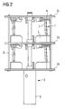
- Figur 2
- eine seitliche Ansicht der Halterung der
Figur 1 , Figur 3- eine perspektivische Ansicht eines Teils der Halterung der
Figur 1 in zerlegtem Zustand, Figur 4- eine seitliche Ansicht eines Teils der Halterung der
Figur 1 in teilweise montiertem Zustand, und Figur 5- eine seitliche Ansicht der Halterung der
Figur 1 im montierten Zustand ohne Versteifungsstangen.
- FIG. 1
- a perspective view of a holder according to the invention,
- FIG. 2
- a side view of the holder of
FIG. 1 . - FIG. 3
- a perspective view of a portion of the holder of
FIG. 1 in disassembled condition, - FIG. 4
- a side view of a portion of the holder of
FIG. 1 in partially assembled condition, and - FIG. 5
- a side view of the holder of
FIG. 1 in assembled condition without stiffening rods.
In der
Die Einspanneinrichtungen 1 weisen jeweils ein unteres, in der Zeichnung nicht gezeigtes Spannelement zur Fixierung eines Schaufelfußes und ein oberes Spannelement 4 zur Fixierung eines Schaufelblatts einer Turbinenschaufel auf, wobei diese jeweils an zwei übereinander angeordneten Halteelementen 2 befestigt sind. Weiterhin sind die Einspanneinrichtungen 1 jeweils mit einem kastenförmig ausgebildeten Maskierungselement 5 für den Schaufelfuß der Turbinenschaufel versehen. Das Maskierungselement 5 weist eine offene Oberseite 6 und eine offene Unterseite auf, wobei die Oberseite 6 ausgebildet ist, um ein durchgeführtes Schaufelblatt einzufassen. An der offenen Unterseite ist eine in der Zeichnung nicht gezeigte Verschlussklappe anbringbar, die das Maskierungselement 5 nach dem Einsetzen der Turbinenschaufel verschließt, so dass der Schaufelfuß der Turbinenschaufel vollständig von dem Maskierungselement 5 umschlossen ist.The clamping devices 1 each have a lower, not shown in the drawing clamping element for fixing a blade root and an
An den oberen Spannelementen 4 ist jeweils zusätzlich lösbar ein Abschattungselement 7 befestigt, das die Abströmkante des Schaufelblatts einer in der Spanneinrichtung 1 fixierten Turbinenschaufel überdeckt.A
Das Gestänge 3 der Halterung wird von einem säulenförmig ausgebildeten zentralen Element 8, den Halteelementen 2 sowie von Versteifungsstangen 9 gebildet, die die übereinander liegenden Halteelemente 2 miteinander verbinden. Das zentrale Element 8 des Gestänges 3 ist so ausgebildet, dass es beispielsweise nach Verbindung mit einem geeigneten Motor automatisch um seine eigene Achse gedreht werden kann. Das gesamte Gestänge 3 ist zerlegbar ausgebildet.The
Um Turbinenschaufeln in der Halterung zu befestigen, werden die Versteifungsstangen 9 und die beiden oberen Halteelemente 2b, 2c entfernt. Dieser Zustand der Halterung ist in der
In einem weiteren Schritt wird das mittlere Halteelement 2b auf das zentrale Element 8 der Halterung aufgeschoben, bis die an der Unterseite des Halteelements 2b ausgebildeten oberen Spannelemente 4 die Spitzen der Schaufelblätter der Turbinenschaufel 10 einfassen. Dabei überdecken die Abschaltungselemente 7 die Abströmkanten der Schaufelblätter. Die Schaufelblätter werden mit Hilfe der oberen Spannelemente 4 fixiert. In der
Danach werden in der oben beschriebenen Weise drei weitere Turbinenschaufeln 10 zwischen den unteren und oberen Spannelementen des mittleren und des oberen Halteelements 2b, 2c fixiert. Die
Zuletzt werden die Versteifungsstangen 9 in die Halterung wieder eingesetzt und verriegelt. In diesem Zustand kann die Halterung mit den Turbinenschaufel 10 in einer Beschichtungsvorrichtung eingesetzt werden.Finally, the stiffening
Jeweils zwei übereinander am Gestänge 3 befestigte Spanneinrichtungen 1 weisen die gleiche räumliche Ausrichtung und Orientierung auf. Folglich haben auch zwei Turbinenschaufeln 10, die in diesen beiden Einspanneinrichtungen fixiert sind, dieselbe räumliche Ausrichtung. Wenn die Halterung als Ganzes dann in einer Beschichtungsvorrichtung angeordnet und während des Beschichtungsvorganges um das zentrale Element 8 gedreht wird, erfolgt eine gleichmäßige Beschichtung der in den Einspanneinrichtungen 1 fixierten Turbinenschaufeln 10.In each case two clamping devices 1 fastened one above the other to the
Claims (6)
die für jede Turbinenschaufel (10) eine Einspanneinrichtung (1) zur Fixierung von Schaufelfuß und Schaufelblatt aufweist,
wobei wenigstens zwei Einspanneinrichtungen (1) übereinander an einem Gestänge (3) der Halterung angebracht sind,
dadurch gekennzeichnet, dass
die wenigstens zwei Einspanneinrichtungen (1) weitestgehend mit der gleichen räumlichen Ausrichtung und Orientierung an dem Gestänge (3) befestigt sind.Support for at least two turbine blades (10) for use in a coating device,
which has for each turbine blade (10) a clamping device (1) for fixing the blade root and blade,
wherein at least two clamping devices (1) are mounted one above the other on a linkage (3) of the holder,
characterized in that
the at least two clamping devices (1) are fastened, as far as possible, to the linkage (3) with the same spatial orientation and orientation.
dadurch gekennzeichnet, dass
die Einspanneinrichtungen (1) mit jeweils einem Maskierungselement (6) versehen sind, welches den Schaufelfuß im eingespannten Zustand umschließt.Holder according to claim 1,
characterized in that
the clamping devices (1) are each provided with a masking element (6) which encloses the blade root in the clamped state.
dadurch gekennzeichnet, dass
die Einspanneinrichtungen (1) jeweils ein Abschattungselement (7) für die Abströmkante des Schaufelblatts aufweisen.Holder according to one of the preceding claims,
characterized in that
the clamping devices (1) each have a shading element (7) for the trailing edge of the blade.
dadurch gekennzeichnet, dass
das Gestänge (3) ein zentrales Element (8) aufweist, über das die Halterung als Ganzes drehbar ist.Holder according to one of the preceding claims,
characterized in that
the linkage (3) has a central element (8) over which the holder as a whole is rotatable.
dadurch gekennzeichnet, dass
jeweils drei Einspanneinrichtungen (1) in zwei Ebenen übereinander insbesondere sternförmig am Gestänge (3) angebracht sind.Holder according to one of the preceding claims,
characterized in that
each three clamping devices (1) in two planes one above the other, in particular star-shaped mounted on the linkage (3).
dadurch gekennzeichnet, dass
das Gestänge (3) zerlegbar ausgebildet ist.Holder according to one of the preceding claims,
characterized in that
the linkage (3) is designed dismantled.
Priority Applications (2)
| Application Number | Priority Date | Filing Date | Title |
|---|---|---|---|
| DE200750003308 DE502007003308D1 (en) | 2007-07-12 | 2007-07-12 | Support for turbine blades |
| EP20070013720 EP2014377B1 (en) | 2007-07-12 | 2007-07-12 | Mounting for turbine blades |
Applications Claiming Priority (1)
| Application Number | Priority Date | Filing Date | Title |
|---|---|---|---|
| EP20070013720 EP2014377B1 (en) | 2007-07-12 | 2007-07-12 | Mounting for turbine blades |
Publications (2)
| Publication Number | Publication Date |
|---|---|
| EP2014377A1 true EP2014377A1 (en) | 2009-01-14 |
| EP2014377B1 EP2014377B1 (en) | 2010-03-31 |
Family
ID=38611057
Family Applications (1)
| Application Number | Title | Priority Date | Filing Date |
|---|---|---|---|
| EP20070013720 Not-in-force EP2014377B1 (en) | 2007-07-12 | 2007-07-12 | Mounting for turbine blades |
Country Status (2)
| Country | Link |
|---|---|
| EP (1) | EP2014377B1 (en) |
| DE (1) | DE502007003308D1 (en) |
Cited By (2)
| Publication number | Priority date | Publication date | Assignee | Title |
|---|---|---|---|---|
| WO2013086286A3 (en) * | 2011-12-08 | 2013-08-01 | Prexair S. T. Technology, Inc. | Tooling fixture assembly for use in a coating operation |
| DE102014205426A1 (en) * | 2014-03-24 | 2015-09-24 | Siemens Aktiengesellschaft | Frame for holding components |
Families Citing this family (1)
| Publication number | Priority date | Publication date | Assignee | Title |
|---|---|---|---|---|
| CN109397143A (en) * | 2018-12-13 | 2019-03-01 | 株洲市超宇实业有限责任公司 | Slot blade coated fixture |
Citations (7)
| Publication number | Priority date | Publication date | Assignee | Title |
|---|---|---|---|---|
| US2645611A (en) * | 1948-09-20 | 1953-07-14 | Shwayder Bros Inc | Method of and bath for electrolytic polishing |
| US3783007A (en) * | 1971-10-01 | 1974-01-01 | Texas Instruments Inc | Metal carbonitrile coatings |
| US4271005A (en) * | 1979-12-03 | 1981-06-02 | United Technologies Corporation | Workpiece support apparatus for use with cathode sputtering devices |
| US5264245A (en) * | 1991-12-04 | 1993-11-23 | Howmet Corporation | CVD method for forming uniform coatings |
| EP0863226A1 (en) * | 1997-03-06 | 1998-09-09 | United Technologies Corporation | Modular fixture for coating apparatus |
| WO2004055227A2 (en) * | 2002-12-14 | 2004-07-01 | Mtu Aero Engines Gmbh | Method and device for the cvd coating of workpieces |
| EP0975435B1 (en) * | 1997-01-13 | 2006-11-29 | United Technologies Corporation | Modular coating fixture |
-
2007
- 2007-07-12 EP EP20070013720 patent/EP2014377B1/en not_active Not-in-force
- 2007-07-12 DE DE200750003308 patent/DE502007003308D1/en active Active
Patent Citations (7)
| Publication number | Priority date | Publication date | Assignee | Title |
|---|---|---|---|---|
| US2645611A (en) * | 1948-09-20 | 1953-07-14 | Shwayder Bros Inc | Method of and bath for electrolytic polishing |
| US3783007A (en) * | 1971-10-01 | 1974-01-01 | Texas Instruments Inc | Metal carbonitrile coatings |
| US4271005A (en) * | 1979-12-03 | 1981-06-02 | United Technologies Corporation | Workpiece support apparatus for use with cathode sputtering devices |
| US5264245A (en) * | 1991-12-04 | 1993-11-23 | Howmet Corporation | CVD method for forming uniform coatings |
| EP0975435B1 (en) * | 1997-01-13 | 2006-11-29 | United Technologies Corporation | Modular coating fixture |
| EP0863226A1 (en) * | 1997-03-06 | 1998-09-09 | United Technologies Corporation | Modular fixture for coating apparatus |
| WO2004055227A2 (en) * | 2002-12-14 | 2004-07-01 | Mtu Aero Engines Gmbh | Method and device for the cvd coating of workpieces |
Cited By (4)
| Publication number | Priority date | Publication date | Assignee | Title |
|---|---|---|---|---|
| WO2013086286A3 (en) * | 2011-12-08 | 2013-08-01 | Prexair S. T. Technology, Inc. | Tooling fixture assembly for use in a coating operation |
| KR20140108252A (en) * | 2011-12-08 | 2014-09-05 | 프랙스에어 에스.티. 테크놀로지, 인코포레이티드 | Tooling fixture assembly for use in a coating operation |
| US9789513B2 (en) | 2011-12-08 | 2017-10-17 | Praxair S.T. Technology, Inc. | Tooling fixture assembly for use in a coating operation |
| DE102014205426A1 (en) * | 2014-03-24 | 2015-09-24 | Siemens Aktiengesellschaft | Frame for holding components |
Also Published As
| Publication number | Publication date |
|---|---|
| DE502007003308D1 (en) | 2010-05-12 |
| EP2014377B1 (en) | 2010-03-31 |
Similar Documents
| Publication | Publication Date | Title |
|---|---|---|
| DE10305543C5 (en) | Method for assembling rotor blades and a rotor blade for a wind energy plant | |
| DE3110318C2 (en) | ||
| DE19526747C2 (en) | Air flow direction control device of an air conditioner | |
| DE69737037T2 (en) | MODULAR FASTENING FOR WORKPIECES TO COAT | |
| DE2215375A1 (en) | Rotary filter drum | |
| EP1762303A1 (en) | Method for preparing turbine blades for spray coating and device for holding such blades | |
| DE1500949B1 (en) | Installation device for dowels in lightweight composite panels | |
| EP2014377B1 (en) | Mounting for turbine blades | |
| DE202011000688U1 (en) | Device for accommodating filters for microscopes | |
| WO2009127203A1 (en) | Strut for an intermediate turbine housing, intermediate turbine housing, and method for producing an intermediate turbine housing | |
| DE19643336C2 (en) | Method for dismantling the front bearing housing or LP compressor shaft part of an aircraft engine | |
| EP2878812B1 (en) | Wind turbine rotor blade for a rotor with a spinner | |
| EP2659023A1 (en) | Holder for boring head coating | |
| DE2810457C2 (en) | A method of temporarily covering an opening in an object to be surface treated | |
| DE102007056690A1 (en) | Plant for the production of a lightweight structure | |
| DE202010000513U1 (en) | Hair replacement with integrated safety device | |
| DE2811669C2 (en) | Planer head with reversible knives | |
| EP1055873A2 (en) | Lamp | |
| DE19603978A1 (en) | Ventilation tile for tile stove | |
| DE4242851A1 (en) | Process for producing a guide vane for turbomachinery, in particular for axial compressors | |
| DE202013009757U1 (en) | Insect revolving door | |
| DE2307405C3 (en) | Gas heater | |
| DE1940722A1 (en) | Rotor for thin-film treatment apparatus | |
| DE2643923C2 (en) | Bracket for the drive unit of a roller shutter | |
| DE3114101C2 (en) | Air inlet ducts |
Legal Events
| Date | Code | Title | Description |
|---|---|---|---|
| PUAI | Public reference made under article 153(3) epc to a published international application that has entered the european phase |
Free format text: ORIGINAL CODE: 0009012 |
|
| AK | Designated contracting states |
Kind code of ref document: A1 Designated state(s): AT BE BG CH CY CZ DE DK EE ES FI FR GB GR HU IE IS IT LI LT LU LV MC MT NL PL PT RO SE SI SK TR |
|
| AX | Request for extension of the european patent |
Extension state: AL BA HR MK RS |
|
| 17P | Request for examination filed |
Effective date: 20090223 |
|
| 17Q | First examination report despatched |
Effective date: 20090401 |
|
| AKX | Designation fees paid |
Designated state(s): CH DE FR GB IT LI NL |
|
| GRAP | Despatch of communication of intention to grant a patent |
Free format text: ORIGINAL CODE: EPIDOSNIGR1 |
|
| GRAS | Grant fee paid |
Free format text: ORIGINAL CODE: EPIDOSNIGR3 |
|
| GRAA | (expected) grant |
Free format text: ORIGINAL CODE: 0009210 |
|
| AK | Designated contracting states |
Kind code of ref document: B1 Designated state(s): CH DE FR GB IT LI NL |
|
| REG | Reference to a national code |
Ref country code: CH Ref legal event code: EP Ref country code: GB Ref legal event code: FG4D Free format text: NOT ENGLISH |
|
| REG | Reference to a national code |
Ref country code: CH Ref legal event code: NV Representative=s name: SIEMENS SCHWEIZ AG |
|
| REF | Corresponds to: |
Ref document number: 502007003308 Country of ref document: DE Date of ref document: 20100512 Kind code of ref document: P |
|
| REG | Reference to a national code |
Ref country code: NL Ref legal event code: VDEP Effective date: 20100331 |
|
| PG25 | Lapsed in a contracting state [announced via postgrant information from national office to epo] |
Ref country code: NL Free format text: LAPSE BECAUSE OF FAILURE TO SUBMIT A TRANSLATION OF THE DESCRIPTION OR TO PAY THE FEE WITHIN THE PRESCRIBED TIME-LIMIT Effective date: 20100331 |
|
| PLBE | No opposition filed within time limit |
Free format text: ORIGINAL CODE: 0009261 |
|
| STAA | Information on the status of an ep patent application or granted ep patent |
Free format text: STATUS: NO OPPOSITION FILED WITHIN TIME LIMIT |
|
| 26N | No opposition filed |
Effective date: 20110104 |
|
| PG25 | Lapsed in a contracting state [announced via postgrant information from national office to epo] |
Ref country code: IT Free format text: LAPSE BECAUSE OF FAILURE TO SUBMIT A TRANSLATION OF THE DESCRIPTION OR TO PAY THE FEE WITHIN THE PRESCRIBED TIME-LIMIT Effective date: 20100331 |
|
| REG | Reference to a national code |
Ref country code: FR Ref legal event code: ST Effective date: 20110331 |
|
| PG25 | Lapsed in a contracting state [announced via postgrant information from national office to epo] |
Ref country code: FR Free format text: LAPSE BECAUSE OF NON-PAYMENT OF DUE FEES Effective date: 20100802 |
|
| PGFP | Annual fee paid to national office [announced via postgrant information from national office to epo] |
Ref country code: GB Payment date: 20120709 Year of fee payment: 6 |
|
| PGFP | Annual fee paid to national office [announced via postgrant information from national office to epo] |
Ref country code: DE Payment date: 20120906 Year of fee payment: 6 |
|
| PGFP | Annual fee paid to national office [announced via postgrant information from national office to epo] |
Ref country code: CH Payment date: 20121011 Year of fee payment: 6 |
|
| REG | Reference to a national code |
Ref country code: CH Ref legal event code: PL |
|
| GBPC | Gb: european patent ceased through non-payment of renewal fee |
Effective date: 20130712 |
|
| REG | Reference to a national code |
Ref country code: DE Ref legal event code: R119 Ref document number: 502007003308 Country of ref document: DE Effective date: 20140201 |
|
| PG25 | Lapsed in a contracting state [announced via postgrant information from national office to epo] |
Ref country code: CH Free format text: LAPSE BECAUSE OF NON-PAYMENT OF DUE FEES Effective date: 20130731 Ref country code: DE Free format text: LAPSE BECAUSE OF NON-PAYMENT OF DUE FEES Effective date: 20140201 Ref country code: GB Free format text: LAPSE BECAUSE OF NON-PAYMENT OF DUE FEES Effective date: 20130712 Ref country code: LI Free format text: LAPSE BECAUSE OF NON-PAYMENT OF DUE FEES Effective date: 20130731 |