EP2014136B1 - Détection d'erreurs de diodes électroluminescentes - Google Patents
Détection d'erreurs de diodes électroluminescentes Download PDFInfo
- Publication number
- EP2014136B1 EP2014136B1 EP07724386.3A EP07724386A EP2014136B1 EP 2014136 B1 EP2014136 B1 EP 2014136B1 EP 07724386 A EP07724386 A EP 07724386A EP 2014136 B1 EP2014136 B1 EP 2014136B1
- Authority
- EP
- European Patent Office
- Prior art keywords
- light
- emitting diode
- current
- diode arrangement
- voltage
- Prior art date
- Legal status (The legal status is an assumption and is not a legal conclusion. Google has not performed a legal analysis and makes no representation as to the accuracy of the status listed.)
- Not-in-force
Links
Images


Classifications
-
- H—ELECTRICITY
- H05—ELECTRIC TECHNIQUES NOT OTHERWISE PROVIDED FOR
- H05B—ELECTRIC HEATING; ELECTRIC LIGHT SOURCES NOT OTHERWISE PROVIDED FOR; CIRCUIT ARRANGEMENTS FOR ELECTRIC LIGHT SOURCES, IN GENERAL
- H05B45/00—Circuit arrangements for operating light-emitting diodes [LED]
- H05B45/50—Circuit arrangements for operating light-emitting diodes [LED] responsive to malfunctions or undesirable behaviour of LEDs; responsive to LED life; Protective circuits
- H05B45/58—Circuit arrangements for operating light-emitting diodes [LED] responsive to malfunctions or undesirable behaviour of LEDs; responsive to LED life; Protective circuits involving end of life detection of LEDs
-
- H—ELECTRICITY
- H05—ELECTRIC TECHNIQUES NOT OTHERWISE PROVIDED FOR
- H05B—ELECTRIC HEATING; ELECTRIC LIGHT SOURCES NOT OTHERWISE PROVIDED FOR; CIRCUIT ARRANGEMENTS FOR ELECTRIC LIGHT SOURCES, IN GENERAL
- H05B47/00—Circuit arrangements for operating light sources in general, i.e. where the type of light source is not relevant
- H05B47/20—Responsive to malfunctions or to light source life; for protection
- H05B47/23—Responsive to malfunctions or to light source life; for protection of two or more light sources connected in series
- H05B47/235—Responsive to malfunctions or to light source life; for protection of two or more light sources connected in series with communication between the lamps and a central unit
Definitions
- the invention relates to the field of detecting a failure of a light emitting diode.
- Light-emitting diodes have the advantage of a long service life, which is why they are often used, for example, for emergency lighting, which are automatically switched on when a mains supply for other lighting devices such as, for example, gas discharge lamps fails.
- the DE 198 41 490 A1 shows a circuit arrangement which serves to protect a series circuit of at least two LEDs from failure.
- Each of the series-connected light emitting diode is connected in parallel with a bypass device.
- each light emitting diode is a comparator with its two input terminals connected in parallel. That is, at a first terminal of the diode, a first input terminal of the comparator is turned on, while at a second terminal of the diode, a second terminal of the comparator is connected.
- the outputs of all comparators are connected to each other. Each individual comparator only detects whether the voltage differs before the diode and after the diode.
- the DE 34 41 824 C2 shows a very simple circuit for monitoring the functionality of lamps in traffic control. For this purpose, the current through the lamp is monitored as the only parameter.
- the invention has for its object to provide a way of detecting a failure interruption of at least one light emitting diode.
- an operating circuit for a light-emitting diode arrangement which has one or more light-emitting diodes connected in series, to which in each case one element is connected in parallel, which takes over the current through the light-emitting diode in the event of an interruption failure of a light-emitting diode. It is further provided a detection unit which is designed to interrupt a failure of at least one light-emitting diode by detecting the temporal evolution of the diode current and the voltage at the light-emitting diode arrangement to recognize.
- the circuit may be configured to operate the light emitting diode array with constant power. In this case, an interruption failure is detected by an increase in the voltage across the light emitting diode array with simultaneous decrease in the current through the light emitting diode array.
- the circuit may alternatively be configured to operate the light emitting diode array with a constant current. An interrupt failure is detected by an increase in the voltage across the light emitting diode array.
- the detection unit can detect the current and voltage conditions of the light-emitting diode arrangement continuously or at intervals.
- the detection unit can store the detected current and voltage conditions of the light-emitting diode arrangement in a memory and detect an interruption failure of at least one light-emitting diode by comparing current values of the current and voltage conditions of the light-emitting diode arrangement with at least one stored value.
- the circuit can be connected to an external data line and check the current and voltage conditions of the light-emitting diode array to a query on the external data line query out.
- the result of the externally requested check can be transmitted via the external data line.
- the light-emitting diode arrangement can be designed as an emergency lighting, which is automatically switched on in case of failure of the mains supply for main lighting.
- the detection unit may perform the monitoring of the time evolution of the diode current and / or the voltage across the light emitting diode array compensated with respect to the LED temperature.
- the detection unit can be supplied to a direct or indirect temperature information with respect to the LED temperature.
- Another exemplary embodiment relates to an operating method for a light-emitting diode array having one or more light emitting diodes connected in series, to each of which an element is connected in parallel, which takes over the current through the light emitting diode in case of failure of a light emitting diode.
- a detection unit detects an interruption failure of at least one light emitting diode by monitoring the timing of the diode current and the voltage across the light emitting diode array.
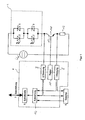
- a light-emitting diode arrangement 1 which has a plurality of light-emitting diodes 2 connected in series in the exemplary embodiment.
- a protective element 3 is connected in parallel, which is designed to take over the power in the event of failure of the associated light-emitting diode 2, which has flowed through the light-emitting diode 2 before the failure.
- the protective element may in particular be an antiparallel-connected Zener diode 3.
- a control unit 4 controls and / or regulates the current and the voltage across the light emitting diode array 1.
- the control unit 4 performs a constant power operation or a constant current operation.
- the control unit 4 detects the actual prevailing actual current 8 by means of a measuring resistor 13 and possibly also the actual voltage 9 of the light-emitting diode arrangement 1 and evaluates it by a controller 10.
- the controller 10 then outputs a control variable for the current and / or power control.
- the controller 10 controls the control input 12 as a transistor implemented linear regulator 11, which is connected in series to the diode line on the low-voltage side.
- the control unit 4 may be functionally connected to an internal or external memory 5 in which at least one set of measured current and voltage values can be stored and read out for later comparison with the corresponding current values.
- the control unit 4 can furthermore have an interface 6 for connecting an external data line 7.
- the data line which may be a bus line 7
- desired values for the power and / or the current of the light-emitting diode arrangement 1 can be supplied, for example, from a control unit.
- instructions can also be supplied via this external data line 7, by means of which the execution of an error check can be instructed by the control unit and / or the result of such a check can be interrogated.
- control unit 4 can be designed to carry out the error check continuously, at intervals and / or by external commands.
- the result of the error check can then be displayed, reported or signaled.
- the error checking aims at detecting a breakdown failure of at least one light emitting diode 2, in which the parallel connected protective element 3 takes over the diode current.
- the control unit 4 monitors the time profile of the current and / or voltage conditions at the light-emitting diode arrangement 1.
- the time profile can be carried out by an evaluation unit 14 by comparing current values with (for example, stored) values from the past.
- the time derivative of the respective parameter can be determined, which will be discussed later in detail on the basis of FIG. 4 will be explained.
- the rapid time change in the event of a fault can be detected by means of a circuit which has a capacitor and / or an inductance.
- a failure is detected if the said evaluation results in a deviation that is greater than a predetermined threshold value.
- an error can be detected if there is a change over time in a short period of time.
- slower temperature drifts can be ruled out.
- the evaluation may be temperature compensated, i. the dependence of the diode characteristics on the temperature response is taken into account.
- the light-emitting diode arrangement 1 can be emergency lighting, in which proper operation is of particular importance.
- the remote inquiry described above may be important.
- FIG. 2 shows, as in the case of the operation of the light-emitting diode array 1 with a constant (regulated) power in the event of an interruption error of at least one light emitting diode. 2 the current through the light emitting diode array 1 decreases as the voltage rises. This can be done by detecting the time changes of current and voltage eg. By a circuit as in FIG. 1 be detected.
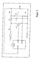
- FIG. 3 shows a possibility of measuring the current and / or the voltage of the diode path 1.
- the current and / or power control is performed by the control unit 4 by clocked driving a circuit breaker 15 of a switching regulator, in a conventional manner continue with a closed switch 15th can be energized choke Lb, whose energy is discharged with an open switch 15 via a diode Db on the diode path 1.
- a mean value fluctuating diode current whose time average depends on the timing of the switch 15.
- FIGS. 1 and 3 Show ways to directly capture the current and / or voltage of the diode path shows FIG. 4 a possible implementation of the detection and evaluation of the time derivatives of the current and / or the voltage of the diode path.
- the current regulation is represented by means of a linear regulator in the form of a transistor 11 whose control terminal 12 is driven by the supply voltage U IN of the light-emitting diode path 1 divided by a voltage divider 16, 17. Via a measuring resistor 13, the current through the linear regulator 11th and thus the current i detected by the LED strip 1. More specifically, by means of a capacitor 18, the time change delta (i) of the diode current can be detected and then compared by a comparator 19 with a reference value i REF .
- the time change delta (U) of the diode voltage U is detected and compared by a comparator 21 with a reference value U REF .
- the output signals of the two comparators 19, 21 are fed to a logic evaluation unit 22, which, for example, outputs an error message if, in a short time, the diode current decreases and at the same time the diode voltage rises, as in FIG FIG. 2 is shown.
- control unit can take into account a temperature information regarding the temperature of the light-emitting diodes in the fault detection, in order thus to compensate for the temperature dependence of the light-emitting diode forward voltage for a given current.
- the temperature measurement can be done directly via a temperature sensor or indirectly.
- the detection unit can determine, by means of access to a table stored in advance, the corrected forward voltage associated with the temperature of the light-emitting diodes and make them the basis for error detection.
Landscapes
- Circuit Arrangement For Electric Light Sources In General (AREA)
- Led Devices (AREA)
Claims (16)
- Circuit d'alimentation pour un agencement à diode électroluminescente (1), qui présente une ou plusieurs diodes électroluminescentes connectées en série (2), auxquelles est connecté en parallèle respectivement un élément (3) qui, en cas de défaillance d'interruption d'une diode électroluminescente (2), prend en charge le courant à travers la diode électroluminescente (2),
caractérisé en ce qu'une unité de détection (4) est prévue, laquelle est conçue pour détecter une défaillance d'interruption d'au moins une diode électroluminescente (2) au moyen d'une surveillance de l'évolution dans le temps du courant de diode et de la tension aux bornes de l'agencement à diode électroluminescente (1), dans lequel- l'unité de détection (4) stocke dans une mémoire (5) des valeurs de courant et de tension détectées de l'agencement à diode électroluminescente (1) et détecte une défaillance d'interruption d'au moins une diode électroluminescente (1) au moyen d'une comparaison (14) de valeurs de courant et de tension actuelles de l'agencement à diode électroluminescente (1) avec au moins une valeur mémorisée précédemment, ou- l'unité de détection (4) détecte la dérivée par rapport au temps du courant de diode et de la tension aux bornes de l'agencement à diode électroluminescente (1). - Circuit selon la revendication 1,
qui est conçu pour alimenter l'agencement à diode électroluminescente (1) avec une puissance constante, dans lequel une défaillance d'interruption est détectée au moyen d'une augmentation de la tension aux bornes de l'agencement à diode électroluminescente (1) en cas de diminution simultanée du courant à travers l'agencement à diode électroluminescente (1). - Circuit selon la revendication 1,
qui est conçu pour alimenter l'agencement à diode électroluminescente (1) avec un courant constant, dans lequel une défaillance d'interruption est détectée au moyen d'une augmentation de la tension aux bornes de l'agencement à diode électroluminescente (1). - Circuit selon l'une des revendications précédentes,
dans lequel l'unité de détection détecte les états du courant et de la tension de l'agencement à diode électroluminescente (1) de manière continue ou intermittente. - Circuit selon l'une des revendications précédentes,
qui est relié à une ligne de données externe (7) et qui examine les états du courant et de la tension de l'agencement à diode électroluminescente suite à une requête parvenue par l'intermédiaire de la ligne de données externe. - Circuit selon la revendication 5,
qui transmet le résultat de l'examen demandé de manière externe par l'intermédiaire de la ligne de données externe (7). - Circuit selon l'une des revendications précédentes,
dans lequel l'agencement à diode électroluminescente (1) est conçu en tant qu'éclairage de secours qui est mis en marche automatiquement en cas d'un dysfonctionnement ou d'une défaillance de l'alimentation réseau. - Circuit selon l'une des revendications précédentes,
dans lequel l'unité de détection exécute la surveillance de l'évolution dans le temps du courant de diode et de la tension aux bornes de l'agencement à diode électroluminescente (1) d'une manière compensée relativement à la température de diode électroluminescente, et, pour ce faire, une information directe ou indirecte de température relativement à la température de diode électroluminescente est fournie à l'unité de détection. - Procédé d'alimentation pour un agencement à diode électroluminescente, lequel présente une ou plusieurs diodes électroluminescentes connectées en série, auxquelles est connecté en parallèle respectivement un élément qui, en cas de défaillance d'interruption d'une diode électroluminescente, prend en charge le courant à travers la diode électroluminescente,
caractérisé en ce qu'une défaillance d'interruption d'au moins une diode électroluminescente est détectée au moyen d'une surveillance de l'évolution dans le temps du courant de diode et de la tension aux bornes de l'agencement à diode électroluminescente,
dans lequel des valeurs de courant et de tension détectées de l'agencement à diode électroluminescente sont stockées dans une mémoire,
dans lequel une défaillance d'interruption d'au moins une diode électroluminescente est détectée au moyen d'une comparaison de valeurs de courant et de tension actuelles de l'agencement à diode électroluminescente avec au moins une valeur mémorisée précédemment, ou
dans lequel la dérivée par rapport au temps du courant de diode et de la tension aux bornes de l'agencement à diode électroluminescente est détectée. - Procédé d'alimentation selon la revendication 9,
dans lequel l'agencement à diode électroluminescente est alimenté avec une puissance constante et une défaillance d'interruption est détectée au moyen d'une augmentation de la tension aux bornes de l'agencement à diode électroluminescente en cas de diminution simultanée du courant à travers l'agencement à diode électroluminescente. - Procédé d'alimentation selon la revendication 9,
dans lequel l'agencement à diode électroluminescente est alimenté avec un courant constant, et une défaillance d'interruption est détectée au moyen d'une augmentation de la tension aux bornes de l'agencement à diode électroluminescente. - Procédé d'alimentation selon l'une des revendications 9 à 11,
dans lequel, pour détecter une défaillance d'erreur, les états du courant et de la tension de l'agencement à diode électroluminescente sont détectés de manière continue ou intermittente. - Procédé d'alimentation selon la revendication 12,
dans lequel les états détectées du courant et de la tension de l'agencement à diode électroluminescente sont stockés dans une mémoire et une défaillance d'interruption d'au moins une diode électroluminescente est détectée au moyen d'une comparaison de valeurs actuelles des états du courant et de la tension de l'agencement à diode électroluminescente avec au moins une valeur mémorisée précédemment. - Procédé d'alimentation selon l'une des revendications 9 à 13,
dans lequel les états du courant et de la tension de l'agencement à diode électroluminescente sont examinés suite à une requête parvenue par l'intermédiaire de la ligne de données externe. - Procédé d'alimentation selon la revendication 14,
dans lequel le résultat de l'examen demandé de manière externe est envoyé en retour par l'intermédiaire de la ligne de données externe. - Procédé d'alimentation selon l'une des revendications 9 à 15,
dans lequel l'agencement à diode électroluminescente est utilisé en tant qu'éclairage de secours qui est mis en marche automatiquement en cas de défaillance de l'alimentation réseau.
Priority Applications (1)
| Application Number | Priority Date | Filing Date | Title |
|---|---|---|---|
| EP11156563A EP2343954A3 (fr) | 2006-04-21 | 2007-04-19 | Détection de défaillance pour LED |
Applications Claiming Priority (2)
| Application Number | Priority Date | Filing Date | Title |
|---|---|---|---|
| DE102006018575A DE102006018575A1 (de) | 2006-04-21 | 2006-04-21 | Fehlererkennung von Leuchtdioden |
| PCT/EP2007/003449 WO2007121927A1 (fr) | 2006-04-21 | 2007-04-19 | Détection d'erreurs de diodes électroluminescentes |
Related Child Applications (1)
| Application Number | Title | Priority Date | Filing Date |
|---|---|---|---|
| EP11156563.6 Division-Into | 2011-03-02 |
Publications (2)
| Publication Number | Publication Date |
|---|---|
| EP2014136A1 EP2014136A1 (fr) | 2009-01-14 |
| EP2014136B1 true EP2014136B1 (fr) | 2013-12-11 |
Family
ID=37103158
Family Applications (2)
| Application Number | Title | Priority Date | Filing Date |
|---|---|---|---|
| EP11156563A Withdrawn EP2343954A3 (fr) | 2006-04-21 | 2007-04-19 | Détection de défaillance pour LED |
| EP07724386.3A Not-in-force EP2014136B1 (fr) | 2006-04-21 | 2007-04-19 | Détection d'erreurs de diodes électroluminescentes |
Family Applications Before (1)
| Application Number | Title | Priority Date | Filing Date |
|---|---|---|---|
| EP11156563A Withdrawn EP2343954A3 (fr) | 2006-04-21 | 2007-04-19 | Détection de défaillance pour LED |
Country Status (3)
| Country | Link |
|---|---|
| EP (2) | EP2343954A3 (fr) |
| DE (1) | DE102006018575A1 (fr) |
| WO (1) | WO2007121927A1 (fr) |
Families Citing this family (8)
| Publication number | Priority date | Publication date | Assignee | Title |
|---|---|---|---|---|
| DE102008047731B4 (de) * | 2008-09-18 | 2020-06-04 | HELLA GmbH & Co. KGaA | Verfahren zur Fehlererkennung in einer Beleuchtungsvorrichtung |
| DE102008048701B4 (de) * | 2008-09-24 | 2020-06-04 | HELLA GmbH & Co. KGaA | Verfahren zum Betrieb einer Reihenschaltung von mindestens zwei LED's |
| FR2937492B1 (fr) * | 2008-10-16 | 2012-05-25 | A R P Signal | Dispositif de generation de lumiere et systeme a feux de signalisation utilisant un tel dispositif. |
| DE102009017989A1 (de) * | 2009-04-21 | 2010-10-28 | Vossloh-Schwabe Optoelectronic Gmbh & Co. Kg | LED-Überwachungseinrichtung |
| DE102009029909A1 (de) * | 2009-06-19 | 2010-12-23 | Hella Kgaa Hueck & Co. | Verfahren zur Ausfallerkennung von Leuchtdioden und Schaltungsanordnung |
| DE102009031040A1 (de) * | 2009-06-30 | 2011-01-05 | GM Global Technology Operations, Inc., Detroit | Fahrzeug-Blinker, Fahrzeug-Blinker-Steuergerät und Verfahren zum Betreiben eines Fahrzeug-Blinker-Steuergeräts |
| AT512751B1 (de) * | 2012-03-29 | 2015-03-15 | Din Dietmar Nocker Facilityman Gmbh | Schaltungsanordnung und Verfahren zum Testen eines Leuchtdiodenzweigs einer Schaltungsanordnung |
| EP3125648B1 (fr) * | 2015-07-31 | 2022-11-09 | Yunex GmbH | Circuit de commande de diodes d'éclairage pour un indicateur |
Citations (1)
| Publication number | Priority date | Publication date | Assignee | Title |
|---|---|---|---|---|
| DE3441824A1 (de) * | 1983-11-25 | 1985-06-05 | Ferranti plc, Gatley, Cheadle, Cheshire | Detektor zur feststellung des ausfalls einer lampe |
Family Cites Families (9)
| Publication number | Priority date | Publication date | Assignee | Title |
|---|---|---|---|---|
| JP2991893B2 (ja) * | 1993-05-31 | 1999-12-20 | 富士通株式会社 | 発光素子の駆動回路及びこれを用いた光増幅中継器 |
| DE19602891A1 (de) * | 1996-01-27 | 1997-08-07 | Kammerer Gmbh M | Verfahren und Anordnung zur Einstellung der Helligkeit eines strom- oder spannungsgesteuerten Leuchtmittels zur Hinterleuchtung einer Anzeige, insbesondere für Kraftfahrzeuge |
| DE19841490B4 (de) | 1998-09-10 | 2005-06-30 | Infineon Technologies Ag | Schaltungsanordnung zum Schutz einer Serienschaltung aus mindestens zwei Leuchdioden vor dem Ausfall |
| DE10025821A1 (de) * | 2000-05-25 | 2002-07-25 | Sickinger Monika | Led-Lichtquelle |
| US6650064B2 (en) * | 2000-09-29 | 2003-11-18 | Aerospace Optics, Inc. | Fault tolerant led display design |
| EP1322139A1 (fr) * | 2001-12-19 | 2003-06-25 | Toyoda Gosei Co., Ltd. | Lampe à diodes électroluminescentes pour véhicules |
| CA2391681A1 (fr) * | 2002-06-26 | 2003-12-26 | Star Headlight & Lantern Co. Of Canada Ltd. | Voyant d'avertissement a semi-conducteurs avec circuit d'excitation commande par microprocesseur |
| US20050001562A1 (en) * | 2003-07-02 | 2005-01-06 | 911Ep, Inc. | LED compensation circuit |
| JP4771354B2 (ja) * | 2004-09-17 | 2011-09-14 | 株式会社小糸製作所 | 車両用灯具の点灯制御回路 |
-
2006
- 2006-04-21 DE DE102006018575A patent/DE102006018575A1/de not_active Withdrawn
-
2007
- 2007-04-19 EP EP11156563A patent/EP2343954A3/fr not_active Withdrawn
- 2007-04-19 EP EP07724386.3A patent/EP2014136B1/fr not_active Not-in-force
- 2007-04-19 WO PCT/EP2007/003449 patent/WO2007121927A1/fr not_active Ceased
Patent Citations (1)
| Publication number | Priority date | Publication date | Assignee | Title |
|---|---|---|---|---|
| DE3441824A1 (de) * | 1983-11-25 | 1985-06-05 | Ferranti plc, Gatley, Cheadle, Cheshire | Detektor zur feststellung des ausfalls einer lampe |
Also Published As
| Publication number | Publication date |
|---|---|
| EP2343954A3 (fr) | 2012-06-06 |
| WO2007121927A1 (fr) | 2007-11-01 |
| EP2343954A2 (fr) | 2011-07-13 |
| DE102006018575A1 (de) | 2007-10-25 |
| EP2014136A1 (fr) | 2009-01-14 |
Similar Documents
| Publication | Publication Date | Title |
|---|---|---|
| EP2014136B1 (fr) | Détection d'erreurs de diodes électroluminescentes | |
| EP2347932B1 (fr) | Consommateur électrique de reconnaissance d'une panne dans des véhicules automobiles | |
| DE112014000785B4 (de) | Energieversorgungsvorrichtung | |
| EP2817860B1 (fr) | Dispositif de commutation de sécurité avec bloc d'alimentation | |
| EP2334146B1 (fr) | Circuit de commande pour diodes électroluminescentes | |
| DE19723456C2 (de) | Fehlschlußerkennungseinrichtung für elektrische Verbraucher | |
| DE102009017989A1 (de) | LED-Überwachungseinrichtung | |
| DE102013101050A1 (de) | Sicherheitsschaltvorrichtung mit sicherem Netzteil | |
| DE102014118795A1 (de) | Beleuchtungsbaugruppe und Leuchte | |
| EP2942851B1 (fr) | Procédé de surveillance de la puissance d'un consommateur électrique | |
| WO2015028511A1 (fr) | Dispositif d'alimentation d'au moins une charge en énergie électrique ou de fourniture de puissance électrique à au moins une charge | |
| EP2866526A1 (fr) | Circuit à DEL et procédé de fonctionnement d'un circuit à DEL | |
| EP2866524B1 (fr) | Système et procédé de surveillance de plusieurs rampes de DEL et éclairage à DEL doté d'un tel système | |
| EP2656687B1 (fr) | Appareil de commande de del | |
| DE102012220760A1 (de) | Multifunktionales Betriebsgerät zum Versorgen eines Verbrauchers wie eines LED-Moduls sowie Verfahren zu dessen Betrieb | |
| DE102009045650B4 (de) | Verfahren zur Regelung einer Anzeigevorrichtung | |
| DE102008004791A1 (de) | Lasterkennungsschaltung für dimmbare LED | |
| EP3125651B1 (fr) | Attenuation de dispositifs d'eclairage | |
| EP4077048B1 (fr) | Phare de véhicule comprenant un système de circuit | |
| EP2648481B1 (fr) | Adaptateur destiné au raccordement de lampes à DEL sur une alimentation en tension dotée d'une surveillance de fonction pour lampes à incandescence | |
| DE10121380A1 (de) | Elektronisch abgesicherte Stromversorgung für Schaltungsgruppen, Anzeigevorrichtung für eine sich ändernde Information | |
| DE102014008614B4 (de) | LED-Beleuchtungsvorrichtung für eine Wechselspannungsversorgung in einem Flugzeug sowie Flugzeug mit der LED-Beleuchtungsvorrichtung | |
| EP2887774B1 (fr) | Circuit destiné au fonctionnement d'une unité de lampe pouvant fonctionner sur courant alternatif, ainsi que procédé de fonctionnement d'une telle unité de lampe | |
| DE10040246A1 (de) | Verfahren und Vorrichtung zur Ansteuerung wenigstens eines Verbrauchers | |
| DE102013112815A1 (de) | Sicherheitssteuerung |
Legal Events
| Date | Code | Title | Description |
|---|---|---|---|
| PUAI | Public reference made under article 153(3) epc to a published international application that has entered the european phase |
Free format text: ORIGINAL CODE: 0009012 |
|
| 17P | Request for examination filed |
Effective date: 20080925 |
|
| AK | Designated contracting states |
Kind code of ref document: A1 Designated state(s): AT BE BG CH CY CZ DE DK EE ES FI FR GB GR HU IE IS IT LI LT LU LV MC MT NL PL PT RO SE SI SK TR |
|
| AX | Request for extension of the european patent |
Extension state: AL BA HR MK RS |
|
| 17Q | First examination report despatched |
Effective date: 20090303 |
|
| RAP1 | Party data changed (applicant data changed or rights of an application transferred) |
Owner name: TRIDONIC GMBH & CO KG |
|
| DAX | Request for extension of the european patent (deleted) | ||
| GRAP | Despatch of communication of intention to grant a patent |
Free format text: ORIGINAL CODE: EPIDOSNIGR1 |
|
| INTG | Intention to grant announced |
Effective date: 20130725 |
|
| GRAS | Grant fee paid |
Free format text: ORIGINAL CODE: EPIDOSNIGR3 |
|
| GRAA | (expected) grant |
Free format text: ORIGINAL CODE: 0009210 |
|
| AK | Designated contracting states |
Kind code of ref document: B1 Designated state(s): AT BE BG CH CY CZ DE DK EE ES FI FR GB GR HU IE IS IT LI LT LU LV MC MT NL PL PT RO SE SI SK TR |
|
| REG | Reference to a national code |
Ref country code: GB Ref legal event code: FG4D Free format text: NOT ENGLISH |
|
| REG | Reference to a national code |
Ref country code: CH Ref legal event code: EP |
|
| REG | Reference to a national code |
Ref country code: AT Ref legal event code: REF Ref document number: 645136 Country of ref document: AT Kind code of ref document: T Effective date: 20140115 |
|
| REG | Reference to a national code |
Ref country code: IE Ref legal event code: FG4D Free format text: LANGUAGE OF EP DOCUMENT: GERMAN |
|
| REG | Reference to a national code |
Ref country code: DE Ref legal event code: R096 Ref document number: 502007012574 Country of ref document: DE Effective date: 20140206 |
|
| REG | Reference to a national code |
Ref country code: NL Ref legal event code: VDEP Effective date: 20131211 |
|
| PG25 | Lapsed in a contracting state [announced via postgrant information from national office to epo] |
Ref country code: SE Free format text: LAPSE BECAUSE OF FAILURE TO SUBMIT A TRANSLATION OF THE DESCRIPTION OR TO PAY THE FEE WITHIN THE PRESCRIBED TIME-LIMIT Effective date: 20131211 Ref country code: LT Free format text: LAPSE BECAUSE OF FAILURE TO SUBMIT A TRANSLATION OF THE DESCRIPTION OR TO PAY THE FEE WITHIN THE PRESCRIBED TIME-LIMIT Effective date: 20131211 Ref country code: NL Free format text: LAPSE BECAUSE OF FAILURE TO SUBMIT A TRANSLATION OF THE DESCRIPTION OR TO PAY THE FEE WITHIN THE PRESCRIBED TIME-LIMIT Effective date: 20131211 Ref country code: FI Free format text: LAPSE BECAUSE OF FAILURE TO SUBMIT A TRANSLATION OF THE DESCRIPTION OR TO PAY THE FEE WITHIN THE PRESCRIBED TIME-LIMIT Effective date: 20131211 |
|
| REG | Reference to a national code |
Ref country code: LT Ref legal event code: MG4D |
|
| PG25 | Lapsed in a contracting state [announced via postgrant information from national office to epo] |
Ref country code: CY Free format text: LAPSE BECAUSE OF FAILURE TO SUBMIT A TRANSLATION OF THE DESCRIPTION OR TO PAY THE FEE WITHIN THE PRESCRIBED TIME-LIMIT Effective date: 20131211 Ref country code: LV Free format text: LAPSE BECAUSE OF FAILURE TO SUBMIT A TRANSLATION OF THE DESCRIPTION OR TO PAY THE FEE WITHIN THE PRESCRIBED TIME-LIMIT Effective date: 20131211 |
|
| PG25 | Lapsed in a contracting state [announced via postgrant information from national office to epo] |
Ref country code: EE Free format text: LAPSE BECAUSE OF FAILURE TO SUBMIT A TRANSLATION OF THE DESCRIPTION OR TO PAY THE FEE WITHIN THE PRESCRIBED TIME-LIMIT Effective date: 20131211 Ref country code: IS Free format text: LAPSE BECAUSE OF FAILURE TO SUBMIT A TRANSLATION OF THE DESCRIPTION OR TO PAY THE FEE WITHIN THE PRESCRIBED TIME-LIMIT Effective date: 20140411 |
|
| PG25 | Lapsed in a contracting state [announced via postgrant information from national office to epo] |
Ref country code: PL Free format text: LAPSE BECAUSE OF FAILURE TO SUBMIT A TRANSLATION OF THE DESCRIPTION OR TO PAY THE FEE WITHIN THE PRESCRIBED TIME-LIMIT Effective date: 20131211 Ref country code: CZ Free format text: LAPSE BECAUSE OF FAILURE TO SUBMIT A TRANSLATION OF THE DESCRIPTION OR TO PAY THE FEE WITHIN THE PRESCRIBED TIME-LIMIT Effective date: 20131211 Ref country code: RO Free format text: LAPSE BECAUSE OF FAILURE TO SUBMIT A TRANSLATION OF THE DESCRIPTION OR TO PAY THE FEE WITHIN THE PRESCRIBED TIME-LIMIT Effective date: 20131211 Ref country code: SK Free format text: LAPSE BECAUSE OF FAILURE TO SUBMIT A TRANSLATION OF THE DESCRIPTION OR TO PAY THE FEE WITHIN THE PRESCRIBED TIME-LIMIT Effective date: 20131211 Ref country code: PT Free format text: LAPSE BECAUSE OF FAILURE TO SUBMIT A TRANSLATION OF THE DESCRIPTION OR TO PAY THE FEE WITHIN THE PRESCRIBED TIME-LIMIT Effective date: 20140411 Ref country code: ES Free format text: LAPSE BECAUSE OF FAILURE TO SUBMIT A TRANSLATION OF THE DESCRIPTION OR TO PAY THE FEE WITHIN THE PRESCRIBED TIME-LIMIT Effective date: 20131211 |
|
| REG | Reference to a national code |
Ref country code: DE Ref legal event code: R097 Ref document number: 502007012574 Country of ref document: DE |
|
| PLBE | No opposition filed within time limit |
Free format text: ORIGINAL CODE: 0009261 |
|
| STAA | Information on the status of an ep patent application or granted ep patent |
Free format text: STATUS: NO OPPOSITION FILED WITHIN TIME LIMIT |
|
| PG25 | Lapsed in a contracting state [announced via postgrant information from national office to epo] |
Ref country code: DK Free format text: LAPSE BECAUSE OF FAILURE TO SUBMIT A TRANSLATION OF THE DESCRIPTION OR TO PAY THE FEE WITHIN THE PRESCRIBED TIME-LIMIT Effective date: 20131211 |
|
| 26N | No opposition filed |
Effective date: 20140912 |
|
| PG25 | Lapsed in a contracting state [announced via postgrant information from national office to epo] |
Ref country code: LU Free format text: LAPSE BECAUSE OF FAILURE TO SUBMIT A TRANSLATION OF THE DESCRIPTION OR TO PAY THE FEE WITHIN THE PRESCRIBED TIME-LIMIT Effective date: 20140419 Ref country code: MC Free format text: LAPSE BECAUSE OF FAILURE TO SUBMIT A TRANSLATION OF THE DESCRIPTION OR TO PAY THE FEE WITHIN THE PRESCRIBED TIME-LIMIT Effective date: 20131211 |
|
| REG | Reference to a national code |
Ref country code: CH Ref legal event code: PL |
|
| REG | Reference to a national code |
Ref country code: DE Ref legal event code: R097 Ref document number: 502007012574 Country of ref document: DE Effective date: 20140912 |
|
| REG | Reference to a national code |
Ref country code: IE Ref legal event code: MM4A |
|
| PG25 | Lapsed in a contracting state [announced via postgrant information from national office to epo] |
Ref country code: CH Free format text: LAPSE BECAUSE OF NON-PAYMENT OF DUE FEES Effective date: 20140430 Ref country code: LI Free format text: LAPSE BECAUSE OF NON-PAYMENT OF DUE FEES Effective date: 20140430 |
|
| PG25 | Lapsed in a contracting state [announced via postgrant information from national office to epo] |
Ref country code: SI Free format text: LAPSE BECAUSE OF FAILURE TO SUBMIT A TRANSLATION OF THE DESCRIPTION OR TO PAY THE FEE WITHIN THE PRESCRIBED TIME-LIMIT Effective date: 20131211 |
|
| PG25 | Lapsed in a contracting state [announced via postgrant information from national office to epo] |
Ref country code: IE Free format text: LAPSE BECAUSE OF NON-PAYMENT OF DUE FEES Effective date: 20140419 |
|
| PG25 | Lapsed in a contracting state [announced via postgrant information from national office to epo] |
Ref country code: MT Free format text: LAPSE BECAUSE OF FAILURE TO SUBMIT A TRANSLATION OF THE DESCRIPTION OR TO PAY THE FEE WITHIN THE PRESCRIBED TIME-LIMIT Effective date: 20131211 |
|
| REG | Reference to a national code |
Ref country code: FR Ref legal event code: PLFP Year of fee payment: 10 |
|
| PG25 | Lapsed in a contracting state [announced via postgrant information from national office to epo] |
Ref country code: BG Free format text: LAPSE BECAUSE OF FAILURE TO SUBMIT A TRANSLATION OF THE DESCRIPTION OR TO PAY THE FEE WITHIN THE PRESCRIBED TIME-LIMIT Effective date: 20131211 |
|
| PG25 | Lapsed in a contracting state [announced via postgrant information from national office to epo] |
Ref country code: IT Free format text: LAPSE BECAUSE OF FAILURE TO SUBMIT A TRANSLATION OF THE DESCRIPTION OR TO PAY THE FEE WITHIN THE PRESCRIBED TIME-LIMIT Effective date: 20131211 Ref country code: GR Free format text: LAPSE BECAUSE OF FAILURE TO SUBMIT A TRANSLATION OF THE DESCRIPTION OR TO PAY THE FEE WITHIN THE PRESCRIBED TIME-LIMIT Effective date: 20140312 |
|
| PG25 | Lapsed in a contracting state [announced via postgrant information from national office to epo] |
Ref country code: TR Free format text: LAPSE BECAUSE OF FAILURE TO SUBMIT A TRANSLATION OF THE DESCRIPTION OR TO PAY THE FEE WITHIN THE PRESCRIBED TIME-LIMIT Effective date: 20131211 Ref country code: HU Free format text: LAPSE BECAUSE OF FAILURE TO SUBMIT A TRANSLATION OF THE DESCRIPTION OR TO PAY THE FEE WITHIN THE PRESCRIBED TIME-LIMIT; INVALID AB INITIO Effective date: 20070419 Ref country code: BE Free format text: LAPSE BECAUSE OF FAILURE TO SUBMIT A TRANSLATION OF THE DESCRIPTION OR TO PAY THE FEE WITHIN THE PRESCRIBED TIME-LIMIT Effective date: 20140430 |
|
| PGFP | Annual fee paid to national office [announced via postgrant information from national office to epo] |
Ref country code: FR Payment date: 20160427 Year of fee payment: 10 Ref country code: AT Payment date: 20160428 Year of fee payment: 10 |
|
| REG | Reference to a national code |
Ref country code: AT Ref legal event code: MM01 Ref document number: 645136 Country of ref document: AT Kind code of ref document: T Effective date: 20170419 |
|
| REG | Reference to a national code |
Ref country code: FR Ref legal event code: ST Effective date: 20171229 |
|
| PG25 | Lapsed in a contracting state [announced via postgrant information from national office to epo] |
Ref country code: AT Free format text: LAPSE BECAUSE OF NON-PAYMENT OF DUE FEES Effective date: 20170419 Ref country code: FR Free format text: LAPSE BECAUSE OF NON-PAYMENT OF DUE FEES Effective date: 20170502 |
|
| REG | Reference to a national code |
Ref country code: DE Ref legal event code: R084 Ref document number: 502007012574 Country of ref document: DE |
|
| REG | Reference to a national code |
Ref country code: DE Ref legal event code: R079 Ref document number: 502007012574 Country of ref document: DE Free format text: PREVIOUS MAIN CLASS: H05B0033080000 Ipc: H05B0045000000 |
|
| PGFP | Annual fee paid to national office [announced via postgrant information from national office to epo] |
Ref country code: GB Payment date: 20200429 Year of fee payment: 14 |
|
| GBPC | Gb: european patent ceased through non-payment of renewal fee |
Effective date: 20210419 |
|
| PG25 | Lapsed in a contracting state [announced via postgrant information from national office to epo] |
Ref country code: GB Free format text: LAPSE BECAUSE OF NON-PAYMENT OF DUE FEES Effective date: 20210419 |
|
| P01 | Opt-out of the competence of the unified patent court (upc) registered |
Effective date: 20230530 |
|
| PGFP | Annual fee paid to national office [announced via postgrant information from national office to epo] |
Ref country code: DE Payment date: 20240429 Year of fee payment: 18 |
|
| REG | Reference to a national code |
Ref country code: DE Ref legal event code: R119 Ref document number: 502007012574 Country of ref document: DE |
|
| PG25 | Lapsed in a contracting state [announced via postgrant information from national office to epo] |
Ref country code: DE Free format text: LAPSE BECAUSE OF NON-PAYMENT OF DUE FEES Effective date: 20251104 |