EP2014019B1 - Triangulation mit kolokalisierten sensoren - Google Patents
Triangulation mit kolokalisierten sensoren Download PDFInfo
- Publication number
- EP2014019B1 EP2014019B1 EP06849775.9A EP06849775A EP2014019B1 EP 2014019 B1 EP2014019 B1 EP 2014019B1 EP 06849775 A EP06849775 A EP 06849775A EP 2014019 B1 EP2014019 B1 EP 2014019B1
- Authority
- EP
- European Patent Office
- Prior art keywords
- sensors
- actuator
- event
- location
- circle
- Prior art date
- Legal status (The legal status is an assumption and is not a legal conclusion. Google has not performed a legal analysis and makes no representation as to the accuracy of the status listed.)
- Expired - Lifetime
Links
Images


Classifications
-
- G—PHYSICS
- G01—MEASURING; TESTING
- G01M—TESTING STATIC OR DYNAMIC BALANCE OF MACHINES OR STRUCTURES; TESTING OF STRUCTURES OR APPARATUS, NOT OTHERWISE PROVIDED FOR
- G01M7/00—Vibration-testing of structures; Shock-testing of structures
- G01M7/02—Vibration-testing by means of a shake table
- G01M7/027—Specimen mounting arrangements, e.g. table head adapters
Definitions
- a common location sensing scheme known as triangulation involves the measurement of distance to an event from a reference point.
- sensors are placed in at least three separate locales to determine the location of an object situated at a point between the sensors.
- SHM structural health monitoring
- the invention relates to the in-plane location triangulation of remote objects, features, events or damage using sensors positioned in substantially close proximity to each other.
- the sensors are configured to detect objects, features, events or damage that is located at a position outside of the perimeter formed by the sensors.
- a method of detecting an event in a mechanical structure using sensors and at least one actuator includes generating an excited signal in the structure using the at least one actuator, detecting a reflected signal from the event using each of three of more of the sensors, the three or more of the sensors being positioned around a circle having a central axis, and the sensors and the at least one actuator being positioned concentrically with respect to the central axis, determining respective durations of time for which the reflected signals travel from the event to each of the sensors, and calculating a location of the event by using differences in the respective durations of time for which the reflected signal travels from the event to each of the sensors to determine an angle and a distance at which the event is positioned.
- Implementations of the invention may include one or more of the following features.
- the event may comprise one of an impact event, physical damage or a feature in the structure.
- the sensors may be positioned at even intervals around a circle.
- a method of detecting a position of a feature in a structure using a device having sensors and at least one actuator can include detecting an acoustic event, returning a reflected wave signal from the event to each of the sensors in the device, determining a respective duration of time for which the signal travels from the event to each of the sensors, and calculating a location of the event by using differences in the respective durations of time for which the signal travels from the event to each of the sensors to determine an angle and a distance at which the event is positioned.
- the device includes at least one actuator and at least three sensors being positioned around a circle having a central axis, the at least one actuator and the sensors being positioned concentrically around the central axis, wherein the device is configured to determine the location of the event by using the at least one actuator to generate an excited signal in the structure and using each of the at least three sensors to detect a reflected signal from the event.
- the actuator can surround the at least three sensors.
- the actuator can be positioned in plane with the at least three sensors.
- the at least three sensors can surround the at least one actuator.
- An arrangement of the at least three sensors and an arrangement of the at least one actuator can be concentrically aligned.
- the at least three sensors can be positioned at even intervals around the circle.
- the at least one actuator used to generate the excited signal can be a separate component from the at least three sensors used to detect the reflected signal.
- the event can comprise one of an impact event, physical damage or a feature in the structure.
- the at least one actuator and the at least three sensors may be co-planar.
- Co-located sensors can be used actively to replace phased array methods. Location of an event can be determined within approximately 2 degrees of accuracy. Location of an event can be determined within better than 2 degrees of accuracy. "Halo effect” and "blackout" regions found in traditional phased array can be substantially eliminated. Co-located sensors can be used to replace larger, denser sensor triangulation arrays. The method can be broadly defused in aerospace, automotive, naval and civil applications, or in other fields. Fewer sensors can accomplish detection without limiting the range over which detecting is desired. Co-located sensors can be used in large or in small applications requiring differing power to obtain the desired range and resolution.
- Embodiments of the invention can use an array of actuator and sensor components, including but not limited to piezoelectric wafers, strain gauges, fiber optics or MEMS devices.
- a set of sensors in a node can be used passively to determine the location of an impact event using acoustic emission.
- a set of sensors in a node can actively locate the position (e.g., angle and radius) to a damage feature using Lamb waves or other common ultrasound techniques.
- Embodiments of the invention are directed to co-located sensors in a single package used to determine the position (angle and radius) of an impact event or damage feature located outside of the sensor package using triangulation methods.
- Embodiments of the invention can be directed to piezoelectric-based sensors and an actuator that are positioned in close proximity to one another and can be packaged within a single unit and share a common hardware infrastructure.
- Embodiments of the invention can be used in facilitating damage detection, non-destructive testing (“NDT”), radar, sonar and structural health monitoring (“SHM”).
- NDT non-destructive testing
- SHM structural health monitoring
- Embodiments of the invention relate to a collection of electrical and mechanical components necessary to conduct in-situ damage detection methods.
- Embodiments of the invention can be used in SHM of aircraft, spacecraft, naval vessels and automobiles.
- Embodiments of the invention may be used in other structures using sensor networks and to conduct testing procedures other than NDT and SHM procedures.
- embodiments of the invention can be used for non-destructive evaluation, measurement, usage monitoring (HUMS), security, surveillance, condition monitoring, quality control, radar or cell phone networks.
- HUMS usage monitoring
- Embodiments of the invention can be used for other applications.
- a sensor node 5 is comprised of a piezoelectric wafer 20, sensors 50 and an actuator 60.
- the wafer 20 has a radius 70.
- the sensors 50 are preferably positioned equidistant from each other around a perimeter of the piezoelectric wafer 20.
- a circular wafer 20 having a radius 70 includes sensors 50 positioned at equal distances around the perimeter of the wafer 20.
- the sensors 50 are substantially close in proximity to one another, and in proximity to the actuator 60.
- the node 5 comprises the at least three co-located sensors 50 that allow triangulation using reflected signals.
- the sensors 50 and the actuator 60 are substantially in-plane components capable of connection to a circuit without the use of wires.
- the node 5 can include components, such as those components described in co-pending U.S. Application Serial Nos. 11/071,129 filed March 3, 2005 and entitled, "Sensor Infrastructure," and 11/071,856 filed March 3, 2005 and entitled, "Damage Detection Device,".
- the co-located sensors 50 and the actuator 60 can be a number of alternative shapes and configurations.
- the sensors 50 can be circular, semicircular, square, triangular, rectangular, pie-shaped, hexagonal, octagonal, and any of a number of other shapes.
- Three sensors 50 or greater than three sensors 50 can be used to optimize the location detection.
- the actuator 60 can also be any of a number of shapes configured to be planar to the sensors 50.
- the substantially concentric design of the sensors 50 and the actuator 60 provide omnidirectional operation of the node 5. By having an actuator that surrounds a set of sensors (or vice versa) this allows excited signals (electrical, magnetic, acoustic, vibrational or otherwise) to be emanated omni-directionally from a nearly point source, and for response measurements to be taken from nearly that same location.
- each of the sensors 50 and the actuator 60 can surround, or substantially surround the other.
- the center portion can be the actuator 60, surrounded by one or more than one sensor 50.
- a sensor or a set of sensors can be surrounded by an actuator or a set of actuators.
- an actuator or a set of actuators can be surrounded by a sensor or a set of sensors in the concentric design.
- the in-plane configuration of the actuator 60 and the co-located sensors 50 achieves contact with a material to be monitored or tested using thermoset or thermoplastic tape, epoxy, using a couplant material, or with an externally applied force. Other room temperature or elevated cure methods of contact are possible and envisioned.
- the co-located sensors 50 and the actuator 60 are encapsulated in a housing.
- the node 5 is substantially directly positioned on a material or structure for use.
- the actuator 60 and the co-located sensors 50 can be actuated with an electrical or magnetic field being applied so as to excite through-thickness, axial, shear or radial modes in the actuator. This field can be applied to a parallel face of the actuator 60, or using interdigitated electrode patterns.
- Sensor voltage data can be measured using any of these fields.
- the sensors 50 and the actuator 60 are constructed of a piezo-ceramic material.
- Other known materials can be used, however, such as other piezoelectric materials (PVDF, PMA, etc), piezoresistive materials or magnetorestrictive materials, for example.
- the particular piezoelectric material used for the wafer 20 can be PZT-5A in order to reduce the dependency of performance on temperature, however other grades of PZT such as PZT-5H would also be acceptable.
- the piezoelectric elements are either injection molded, machined or micro-fabricated in either addition or subtraction processes into the desired geometry, typically less than 1" in diameter. Other dimensions are possible and envisioned, and may vary depending on optimizing an application.
- a variety of sensor types can be used to accomplish triangulation, including, but not limited to, sensors that measure stress, strain, vibration, acoustics, temperature, humidity, acceleration, radiation, electric or magnetic fields, light and/or motion.
- a node 5 can be surface-mounted or embedded for applications that include, for example, structural health monitoring, non-destructive evaluation, health usage monitoring, surveillance or security.
- sensors 50 may include an actuator ranging from a 1" diameter to a 0.1" diameter. Sensors can range from 0.2" diameter with 0.01" spacing, to 0.02" diameter with 0.001" spacing. Other dimensions for the sensors and the actuator are possible. For example, the diameters of the sensors and the actuators, and the spacing between the sensors, can be greater than or less than the dimensions stated above. The ratio of the dimensions can be optimized based on predicted performance. Nodes 5 can utilize between 3 and 6 sensors, or more than 6 sensors, inside of an actuator ring, for example.
- the actuator 60 is configured to excite waveforms in a material to create reflected waves that the co-located sensors 50 measure.
- the actuator 60 excites a radial Lamb wave mode, which propagates omni-directionally from the source location.
- the sensors 50 are positioned to measure a time of arrival difference from waves reflected from feature locations (e.g., damage) in order to triangulate a location of an event or feature positioned outside of the perimeter defined by the sensors 50 and the actuator.
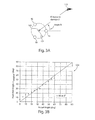
- the distance to an event 110 can be calculated according to various methodologies. For example, in a first in-first out method of determining the position of the event 110, a time of flight of the signal sent from the point 100 is recorded for each of the sensors positioned around the circle 102. A vector is drawn between the sensors 50 with the longest and the shortest times of flight to calculate a distance D to the event 110.
- the method described with respect to FIG. 3A can increase in accuracy as additional sensors are added to a node.
- the co-located sensors 50 can be used in a triangulation method to determine the distance D to the event 110.
- Sensors 50 are positioned in even increments around a circle, for example, 3 sensors are positioned 120-degrees apart from one another around a circle.
- a triangularization calculation is performed, finding the Cartesian coordinates to determine the recorded times of flight using distance formulas.
- Each of the combinations are compared and the combinations of results that yield the highest confidence levels are averaged to produce a final feature position.
- the triangulation method yields substantially accurate results for a small number of sensors. Increasing the number of sensors by more than 3 marginally increases resolution, which was experimentally validated for 3-6 sensors.
- FIG. 3B experiments were conducted using the triangulation technique.
- a plot 120 represents results of testing of a single actuator and 3 sensors positioned on a 1'x 1' aluminum plate with markings at 1-degree increments.
- a 1-kilogram weight was placed on the plate using shear couplant to represent a feature. The weight was placed in several known positions prior to collecting data, in order to compare measured angle-to-damage, with the known angle-to-damage. Distance to the damage was also displayed, using the average time of flight recorded by all sensors to calculate the position.
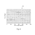
- a Fourier transform can be used in the calculation of the position of the feature, impact event or damage.
- the sensors 50 are positioned around the radius of a circle.
- the sensors 50 are used to plot the time of arrival results in cylindrical coordinates, plot 130.
- a Fourier transform is used to approximate the closest sinew wave that would match this data using the values for amplitude, offset, phase and sensor angle.
- a traditional triangularization method can be used to calculate the feature position based on the implied times of flights for the fixed sensor locations.
- a process 200 for detecting a feature, such as damage or an impact event in a material or structure, using a node 5 having multiple sensors includes the stages shown.
- the process 200 is exemplary only and not limiting.
- the process 200 may be altered, e.g., by having stages added, removed, or rearranged.
- a node 5 is positioned on the surface of a material or a structure for which structural integrity is to be tested or monitored.
- a single node comprises one or more actuators 60, and a number of sensors 50.
- a node 5 contains three sensors 50 equidistant from each other around a perimeter of the node 5, circumscribed by a ring actuator 60.
- the node 5 can be embedded in a material or structure to conduct detection.
- the node 5 can be used to locate other features or events, such as in a radar or sonar application.
- the system can operate continuously, the system can be accessed on demand, for example, to conserve power and computation needs.
- the node 5 collects data related to the structure to which it is affixed.
- the node 5 can collect data actively (e.g., pulse and listen), or passively, for example, using strain and acoustic emission methods.
- Passive damage detection methods can be used continuously to sense the presence of an impact to the structure. Passive methods are generally those that operate by detecting responses due to perturbations of ambient conditions. Acoustic emission can be performed passively to detect and record impact events and approximate the energy of impact.
- Active methods such as Lamb wave techniques can give more information about the type and severity, in addition to the location of damage. Active methods, for example, use an externally supplied energy in the form of a stress or electromagnetic wave to function. Examples of active methods include, but are not limited to, electrical and magnetic impedance measurements, eddy currents, optical fibers that use a laser light source, modal analysis and Lamb wave propagation.
- the nodes pass the collected information to a local processing unit
- the position of damage is determined using the data collected, and using algorithms to triangulate feature locations from a single point.
- a node 5 having three or more sensors 50 equally spaced about a circle having a given radius can record the time of flight of a signal sent to the event for each sensor 50. The time of flight of the signal is used to calculate a position of the event with respect to the position of the sensor 50. More than three sensors can be used in a node to detect the location of an event.
- the collected and processed data is displayed to the user for verification.
- the display is possible using any of a number of methods, for example, through LED indicators, text reports or graphically. It is also possible to set up feedback with the system being monitored for action to take place based upon the results. Data may be communicated to a central location (e.g., ground crew), locally (e.g., operator), or to other nodes for collaboration via data fusion, for example.
- a central location e.g., ground crew
- locally e.g., operator
- other nodes for collaboration via data fusion, for example.
- structural monitoring tests are facilitated with the electronics on a printed circuit board.
- a microprocessor can be encapsulated in the node 5 to initiate testing by triggering the arbitrary function generator to excite the actuator in the node 5 and initiating data collection by a datalogger on the printed circuit board.
- the tests can be initiated remotely by a user, pre-programmed to be executed at certain intervals, or run substantially continuously.
- Digital data from the buffer is collected by a central processor via a wired or wireless data link.
- the data is processed by a central processor.
- the microprocessor on the printed circuit board can provide processing to locally assess damage.
Landscapes
- Physics & Mathematics (AREA)
- General Physics & Mathematics (AREA)
- Testing Or Calibration Of Command Recording Devices (AREA)
- Investigating Or Analyzing Materials By The Use Of Ultrasonic Waves (AREA)
- Length Measuring Devices By Optical Means (AREA)
- Measurement Of Optical Distance (AREA)
- Air Bags (AREA)
- Vehicle Body Suspensions (AREA)
Claims (12)
- Verfahren zum Erkennen eines Events (110) in einer mechanischen Struktur mit Hilfe von Sensoren (50) und wenigstens einem Aktuator (60), wobei das Verfahren Folgendes beinhaltet:Erzeugen eines angeregten Signals in der Struktur mit Hilfe des wenigstens einen Aktuators (60);Erkennen eines reflektierten Signals von dem Event anhand von jedem von drei oder mehr der Sensoren (50), wobei die drei oder mehr der Sensoren (50) um einen Kreis mit einer Mittelachse (100) herum positioniert sind, und die Sensoren und der wenigstens eine Aktuator (60) konzentrisch mit Bezug auf die Mittelachse (100) positioniert sind;Ermitteln von jeweiligen Zeitdauern, während der das reflektierte Signal von dem Event (110) zu jedem der Sensoren (50) wandert; undBerechnen eines Orts des Events (110) anhand von Differenzen zwischen den jeweiligen Zeitdauern, während der das Signal von dem Event (110) zu jedem der Sensoren (50) wandert, um einen Winkel und einen Abstand zu ermitteln, in dem das Event (110) positioniert ist.
- Verfahren nach Anspruch 1, wobei das Event (110) ein Aufprallevent, einen physischen Schaden oder ein Merkmal in der Struktur umfasst.
- Verfahren nach Anspruch 1 oder 2, wobei die Sensoren (50) in gleichmäßigen Intervallen um einen Kreis herum positioniert sind.
- Vorrichtung zum Erkennen eines Events (110) in einer mechanischen Struktur, wobei die Vorrichtung Folgendes umfasst:wenigstens einen Aktuator (60); undwenigstens drei Sensoren (50), die um einen Kreis mit einer Mittelachse (100) herum positioniert sind, wobei der wenigstens eine Aktuator (60) und die Sensoren (50) konzentrisch um die Mittelachse (100) herum positioniert sind,wobei die Vorrichtung zum Ermitteln des Ortes des Events (110) durch Verwenden des wenigstens einen Aktuators (60) zum Erzeugen eines angeregten Signals in der Struktur und durch Verwenden jedes der wenigstens drei Sensoren (50) zum Erkennen eines reflektierten Signals von dem Event (110) konfiguriert ist.
- Vorrichtung nach Anspruch 4, wobei der wenigstens eine Aktuator (60) die wenigstens drei Sensoren (50) umgibt.
- Vorrichtung nach Anspruch 4 oder 5, wobei der wenigstens eine Aktuator (60) in einer Ebene mit den wenigstens drei Sensoren (50) positioniert ist.
- Vorrichtung nach Anspruch 4 oder 6, wobei die wenigstens drei Sensoren (50) den wenigstens einen Aktuator (60) umgeben.
- Vorrichtung nach den Ansprüchen 4 bis 7, wobei eine Anordnung der wenigstens drei Sensoren (50) und eine Anordnung des wenigstens einen Aktuators (60) konzentrisch ausgerichtet sind.
- Vorrichtung nach den Ansprüchen 4 bis 8, wobei die wenigstens drei Sensoren (50) in gleichmäßigen Intervallen um den Kreis herum positioniert sind.
- Vorrichtung nach den Ansprüchen 4 bis 9, wobei der wenigstens eine Aktuator (60), der zum Erzeugen des angeregten Signals benutzt wird, eine separate Komponente von den wenigstens drei Sensoren (50) ist, die zum Erkennen des reflektierten Signals benutzt werden.
- Vorrichtung nach den Ansprüchen 4 bis 10, wobei das Event (110) ein Aufprallevent, einen physischen Schaden oder ein Merkmal in der Struktur umfasst.
- Vorrichtung nach den Ansprüchen 4 bis 11, wobei der wenigstens eine Aktuator (60) und die wenigstens drei Sensoren (50) koplanar sind.
Applications Claiming Priority (2)
| Application Number | Priority Date | Filing Date | Title |
|---|---|---|---|
| US11/406,662 US7533578B2 (en) | 2006-04-18 | 2006-04-18 | Triangulation with co-located sensors |
| PCT/US2006/018004 WO2007133195A2 (en) | 2006-04-18 | 2006-05-09 | Triangulation with co-located sensors |
Publications (3)
| Publication Number | Publication Date |
|---|---|
| EP2014019A2 EP2014019A2 (de) | 2009-01-14 |
| EP2014019A4 EP2014019A4 (de) | 2011-08-24 |
| EP2014019B1 true EP2014019B1 (de) | 2016-01-13 |
Family
ID=38603578
Family Applications (1)
| Application Number | Title | Priority Date | Filing Date |
|---|---|---|---|
| EP06849775.9A Expired - Lifetime EP2014019B1 (de) | 2006-04-18 | 2006-05-09 | Triangulation mit kolokalisierten sensoren |
Country Status (4)
| Country | Link |
|---|---|
| US (1) | US7533578B2 (de) |
| EP (1) | EP2014019B1 (de) |
| ES (1) | ES2567637T3 (de) |
| WO (1) | WO2007133195A2 (de) |
Families Citing this family (13)
| Publication number | Priority date | Publication date | Assignee | Title |
|---|---|---|---|---|
| US7373260B2 (en) * | 2004-03-03 | 2008-05-13 | Metis Design Corporation | Sensor infrastructure |
| US20080211690A1 (en) * | 2005-01-04 | 2008-09-04 | Robert Theodore Kinasewitz | E-field/b-field/acoustic ground target data fused multisensor method and apparatus |
| US7333898B2 (en) * | 2006-06-05 | 2008-02-19 | The Boeing Company | Passive structural assessment and monitoring system and associated method |
| US7809513B2 (en) * | 2007-04-16 | 2010-10-05 | Acellent Technologies, Inc. | Environmental change compensation in a structural health monitoring system |
| KR101608339B1 (ko) * | 2009-06-08 | 2016-04-11 | 삼성전자주식회사 | 위치 측정 장치 및 방법, 및 이동체 |
| KR20110012584A (ko) * | 2009-07-31 | 2011-02-09 | 삼성전자주식회사 | 초음파 기반 3차원 위치 추정 장치 및 방법 |
| US8809788B2 (en) | 2011-10-26 | 2014-08-19 | Redwood Systems, Inc. | Rotating sensor for occupancy detection |
| JP6329338B2 (ja) | 2012-04-30 | 2018-05-23 | ゼネラル・エレクトリック・カンパニイ | ステータベーンの健全性を監視するためのシステムおよび方法 |
| CN103487786B (zh) * | 2013-06-24 | 2015-07-01 | 南京航空航天大学 | 基于二维线阵和空间滤波器的结构冲击无波速定位方法 |
| CN104597126B (zh) * | 2015-01-07 | 2017-02-22 | 北京卫星环境工程研究所 | 基于声传感器的航天器结构健康检测方法 |
| US10571415B2 (en) | 2016-08-02 | 2020-02-25 | Rolls-Royce Corporation | Methods and apparatuses for evaluating ceramic matrix composite components |
| US10866149B1 (en) | 2017-03-22 | 2020-12-15 | University Of Maryland, College Park | System and method for nondestructive detection of structural irregularities using a directional magnetostrictive phased array sensor with a comb-shaped magnetostrictive patch |
| WO2022014597A1 (ja) * | 2020-07-15 | 2022-01-20 | 川崎重工業株式会社 | モニタリングシステム、航空機、及びモニタ方法 |
Family Cites Families (43)
| Publication number | Priority date | Publication date | Assignee | Title |
|---|---|---|---|---|
| US2247246A (en) * | 1938-12-03 | 1941-06-24 | American District Telegraph Co | Micro-wave radio alarm system |
| US3568198A (en) * | 1963-05-31 | 1971-03-02 | Us Army | Correlation curvature radar |
| US3555498A (en) * | 1963-11-12 | 1971-01-12 | Us Navy | Sonar processor and display circuits |
| US3453626A (en) * | 1967-12-21 | 1969-07-01 | Sylvania Electric Prod | Acoustic goniometer |
| US3821740A (en) * | 1972-07-03 | 1974-06-28 | Raytheon Co | Super directive system |
| US3986182A (en) * | 1974-03-27 | 1976-10-12 | Sontrix, Inc. | Multi-zone intrusion detection system |
| US3963677A (en) * | 1974-11-21 | 1976-06-15 | Enger Carl C | Impermeable silicone composition |
| US4242743A (en) * | 1978-11-09 | 1980-12-30 | General Electric Company | Intrusion detection method and apparatus |
| GB8527277D0 (en) * | 1985-11-06 | 1985-12-11 | Formula Systems Ltd | Proximity detector |
| DE3864249D1 (de) * | 1987-12-19 | 1991-09-19 | Thyssen Industrie | Vorrichtung zur ueberwachung eines einem verschleiss unterworfenen bauteils. |
| US5195046A (en) * | 1989-01-10 | 1993-03-16 | Gerardi Joseph J | Method and apparatus for structural integrity monitoring |
| US4958100A (en) * | 1989-02-22 | 1990-09-18 | Massachusetts Institute Of Technology | Actuated truss system |
| US5105918A (en) * | 1989-10-23 | 1992-04-21 | Nippondenso Co., Ltd. | Detection of damping force for shock absorber control |
| JPH0781995B2 (ja) * | 1989-10-25 | 1995-09-06 | 三菱電機株式会社 | 超音波探触子および超音波探傷装置 |
| US5111210A (en) * | 1990-06-22 | 1992-05-05 | Survival Safety Engineering, Inc. | Collision avoidance radar detector system |
| US5305507A (en) * | 1990-10-29 | 1994-04-26 | Trw Inc. | Method for encapsulating a ceramic device for embedding in composite structures |
| US5739626A (en) * | 1991-04-27 | 1998-04-14 | Ngk Spark Plug Co., Ltd. | Piezoelectric sensor |
| DE19509320A1 (de) * | 1995-03-15 | 1996-09-19 | Technologietransfer Anstalt Te | Folgesteuerung für ein selbstfahrendes Fahrzeug |
| US5774376A (en) * | 1995-08-07 | 1998-06-30 | Manning; Raymund A. | Structural health monitoring using active members and neural networks |
| US5528557A (en) * | 1995-08-07 | 1996-06-18 | Northrop Grumman Corporation | Acoustic emission source location by reverse ray tracing |
| US6475639B2 (en) * | 1996-01-18 | 2002-11-05 | Mohsen Shahinpoor | Ionic polymer sensors and actuators |
| US6006163A (en) * | 1997-09-15 | 1999-12-21 | Mcdonnell Douglas Corporation | Active damage interrogation method for structural health monitoring |
| US6370964B1 (en) * | 1998-11-23 | 2002-04-16 | The Board Of Trustees Of The Leland Stanford Junior University | Diagnostic layer and methods for detecting structural integrity of composite and metallic materials |
| US6177903B1 (en) * | 1999-06-14 | 2001-01-23 | Time Domain Corporation | System and method for intrusion detection using a time domain radar array |
| US6617764B2 (en) * | 2000-09-13 | 2003-09-09 | University Of Dayton | High temperature piezoelectric sensor |
| WO2002062206A2 (en) * | 2001-02-08 | 2002-08-15 | University Of South Carolina | In-situ structural health monitoring, diagnostics and prognostics system utilizing thin piezoelectric sensors |
| US6768312B2 (en) * | 2001-06-06 | 2004-07-27 | United Technologies Corporation | Structural integrity monitoring system including wireless electromechanical impedance measurement |
| AU2002351273A1 (en) * | 2001-12-06 | 2003-07-09 | University Of Pittsburgh | Tunable piezoelectric micro-mechanical resonator |
| US6850788B2 (en) * | 2002-03-25 | 2005-02-01 | Masimo Corporation | Physiological measurement communications adapter |
| WO2003106958A2 (en) | 2002-06-14 | 2003-12-24 | University Of South Carolina | Structural health monitoring system utilizing guided lamb waves embedded ultrasonic structural radar |
| US6930596B2 (en) * | 2002-07-19 | 2005-08-16 | Ut-Battelle | System for detection of hazardous events |
| TWI261045B (en) * | 2002-12-30 | 2006-09-01 | Ind Tech Res Inst | Composite nanofibers and their fabrications |
| US20040151071A1 (en) | 2003-02-04 | 2004-08-05 | Kocher Robert William | Wrist-mounted electronic computer component (WECC) |
| US6964201B2 (en) * | 2003-02-25 | 2005-11-15 | Palo Alto Research Center Incorporated | Large dimension, flexible piezoelectric ceramic tapes |
| TWI220328B (en) | 2003-06-06 | 2004-08-11 | Delta Electronics Inc | Fastening structure for tandem motor |
| WO2005006397A2 (en) | 2003-06-10 | 2005-01-20 | University Of Massachusetts | System and method for load sensing using piezoelectric effect |
| US6931173B1 (en) * | 2003-08-14 | 2005-08-16 | Alliance Fiber Optic Products, Inc. | MEMS optical switches with guaranteed switching status |
| AU2004277167A1 (en) * | 2003-09-22 | 2005-04-07 | Kim Hyeung-Yun | Methods for monitoring structural health conditions |
| US7325456B2 (en) * | 2003-09-22 | 2008-02-05 | Hyeung-Yun Kim | Interrogation network patches for active monitoring of structural health conditions |
| US7174255B2 (en) | 2003-11-12 | 2007-02-06 | University Of South Carolina | Self-processing integrated damage assessment sensor for structural health monitoring |
| US8984500B2 (en) * | 2004-06-14 | 2015-03-17 | Hewlett-Packard Development Company, L.P. | Programming a computing node connected to a sensor and an actuator |
| US7075424B1 (en) * | 2004-07-08 | 2006-07-11 | North Carolina A&T State University | System for damage location using a single channel continuous acoustic emission sensor |
| US7185605B1 (en) | 2006-07-03 | 2007-03-06 | Lush Raymon W | Multi-tier collapsible feeder |
-
2006
- 2006-04-18 US US11/406,662 patent/US7533578B2/en active Active
- 2006-05-09 WO PCT/US2006/018004 patent/WO2007133195A2/en not_active Ceased
- 2006-05-09 ES ES06849775.9T patent/ES2567637T3/es not_active Expired - Lifetime
- 2006-05-09 EP EP06849775.9A patent/EP2014019B1/de not_active Expired - Lifetime
Also Published As
| Publication number | Publication date |
|---|---|
| US20070240515A1 (en) | 2007-10-18 |
| EP2014019A4 (de) | 2011-08-24 |
| ES2567637T3 (es) | 2016-04-25 |
| WO2007133195A3 (en) | 2009-04-23 |
| US7533578B2 (en) | 2009-05-19 |
| EP2014019A2 (de) | 2009-01-14 |
| WO2007133195A2 (en) | 2007-11-22 |
| WO2007133195A9 (en) | 2009-07-16 |
Similar Documents
| Publication | Publication Date | Title |
|---|---|---|
| EP1802938B1 (de) | Sensorinfrastruktur mit eingebetteter Elektronik | |
| US7469595B2 (en) | Piezoelectric damage detection device | |
| EP2014019B1 (de) | Triangulation mit kolokalisierten sensoren | |
| Aryan et al. | A baseline‐free and non‐contact method for detection and imaging of structural damage using 3D laser vibrometry | |
| Sun et al. | A methodological review of piezoelectric based acoustic wave generation and detection techniques for structural health monitoring | |
| De Freitas et al. | Equivalent circuit of piezoelectric diaphragms for impedance-based structural health monitoring applications | |
| US10900934B2 (en) | Acoustic black hole for sensing applications | |
| Campeiro et al. | Lamb wave inspection using piezoelectric diaphragms: An initial feasibility study | |
| Reyes et al. | A numerical study on baseline-free damage detection using frequency steerable acoustic transducers | |
| Yu et al. | Correlative sensor array and its applications to identification of damage in plate‐like structures | |
| Hutchins et al. | Structural health monitoring using polymer-based capacitive micromachined ultrasonic transducers (CMUTs) | |
| Du et al. | High-precision probabilistic imaging for interface debonding monitoring based on electromechanical impedance | |
| Boffa et al. | Hybrid guided wave based SHM system for composite structures for impact and delamination detection combining fiber Bragg grating sensing and piezoelectric patches | |
| Liu et al. | Metal core piezoelectric ceramic fiber rosettes for acousto-ultrasonic source localization in plate structures | |
| CN101911728B (zh) | 声换能器 | |
| Rose | Health monitoring of composite structures using guided waves | |
| Salas et al. | Guided wave experimentation using CLoVER transducer for structural health monitoring | |
| Salas et al. | CLoVER: an alterntive concept for damage interrogation in structural health monitoring systems | |
| Wang et al. | Damage detection in metallic plates using d36 piezoelectric phased arrays | |
| Rocha et al. | Determination of the Bandwidth of an Air-Coupled Capacitive Ultrasonic Transducer with a V-Grooved Backplate | |
| Mohammadgholiha et al. | A Numerical Study on Baseline-Free Damage Detection Using Frequency Steerable Acoustic | |
| Balageas et al. | Structural health monitoring for composite structures | |
| Matzkanin | Technology Assessment of MEMS for NDE and Condition-based Maintenance | |
| Ostachowicz et al. | 2 Structural Health | |
| Rocha et al. | On the development of methods and techniques for aircraft structural health monitoring |
Legal Events
| Date | Code | Title | Description |
|---|---|---|---|
| PUAI | Public reference made under article 153(3) epc to a published international application that has entered the european phase |
Free format text: ORIGINAL CODE: 0009012 |
|
| 17P | Request for examination filed |
Effective date: 20081118 |
|
| AK | Designated contracting states |
Kind code of ref document: A2 Designated state(s): AT BE BG CH CY CZ DE DK EE ES FI FR GB GR HU IE IS IT LI LT LU LV MC NL PL PT RO SE SI SK TR |
|
| AX | Request for extension of the european patent |
Extension state: AL BA HR MK YU |
|
| R17D | Deferred search report published (corrected) |
Effective date: 20090423 |
|
| RIC1 | Information provided on ipc code assigned before grant |
Ipc: G01S 13/00 20060101ALI20090428BHEP Ipc: G01S 17/48 20060101ALI20090428BHEP Ipc: G01S 3/02 20060101AFI20090428BHEP Ipc: G01S 5/02 20060101ALI20090428BHEP |
|
| A4 | Supplementary search report drawn up and despatched |
Effective date: 20110727 |
|
| RIC1 | Information provided on ipc code assigned before grant |
Ipc: G01S 5/02 20100101ALI20110721BHEP Ipc: G01S 13/00 20060101ALI20110721BHEP Ipc: G01S 17/48 20060101ALI20110721BHEP Ipc: G01S 3/02 20060101AFI20110721BHEP |
|
| 17Q | First examination report despatched |
Effective date: 20120403 |
|
| R17C | First examination report despatched (corrected) |
Effective date: 20120330 |
|
| DAX | Request for extension of the european patent (deleted) | ||
| REG | Reference to a national code |
Ref country code: DE Ref legal event code: R079 Ref document number: 602006047746 Country of ref document: DE Free format text: PREVIOUS MAIN CLASS: H04L0012280000 Ipc: G01M0007020000 |
|
| GRAP | Despatch of communication of intention to grant a patent |
Free format text: ORIGINAL CODE: EPIDOSNIGR1 |
|
| RIC1 | Information provided on ipc code assigned before grant |
Ipc: G01M 7/02 20060101AFI20150605BHEP |
|
| INTG | Intention to grant announced |
Effective date: 20150708 |
|
| GRAS | Grant fee paid |
Free format text: ORIGINAL CODE: EPIDOSNIGR3 |
|
| GRAA | (expected) grant |
Free format text: ORIGINAL CODE: 0009210 |
|
| AK | Designated contracting states |
Kind code of ref document: B1 Designated state(s): AT BE BG CH CY CZ DE DK EE ES FI FR GB GR HU IE IS IT LI LT LU LV MC NL PL PT RO SE SI SK TR |
|
| REG | Reference to a national code |
Ref country code: GB Ref legal event code: FG4D |
|
| REG | Reference to a national code |
Ref country code: CH Ref legal event code: EP |
|
| REG | Reference to a national code |
Ref country code: IE Ref legal event code: FG4D |
|
| REG | Reference to a national code |
Ref country code: AT Ref legal event code: REF Ref document number: 770847 Country of ref document: AT Kind code of ref document: T Effective date: 20160215 |
|
| RAP2 | Party data changed (patent owner data changed or rights of a patent transferred) |
Owner name: METIS DESIGN CORPORATION |
|
| REG | Reference to a national code |
Ref country code: DE Ref legal event code: R096 Ref document number: 602006047746 Country of ref document: DE |
|
| REG | Reference to a national code |
Ref country code: ES Ref legal event code: FG2A Ref document number: 2567637 Country of ref document: ES Kind code of ref document: T3 Effective date: 20160425 |
|
| REG | Reference to a national code |
Ref country code: SE Ref legal event code: TRGR |
|
| REG | Reference to a national code |
Ref country code: LT Ref legal event code: MG4D |
|
| REG | Reference to a national code |
Ref country code: NL Ref legal event code: MP Effective date: 20160113 |
|
| REG | Reference to a national code |
Ref country code: FR Ref legal event code: PLFP Year of fee payment: 11 |
|
| REG | Reference to a national code |
Ref country code: AT Ref legal event code: MK05 Ref document number: 770847 Country of ref document: AT Kind code of ref document: T Effective date: 20160113 |
|
| PG25 | Lapsed in a contracting state [announced via postgrant information from national office to epo] |
Ref country code: NL Free format text: LAPSE BECAUSE OF FAILURE TO SUBMIT A TRANSLATION OF THE DESCRIPTION OR TO PAY THE FEE WITHIN THE PRESCRIBED TIME-LIMIT Effective date: 20160113 |
|
| PG25 | Lapsed in a contracting state [announced via postgrant information from national office to epo] |
Ref country code: GR Free format text: LAPSE BECAUSE OF FAILURE TO SUBMIT A TRANSLATION OF THE DESCRIPTION OR TO PAY THE FEE WITHIN THE PRESCRIBED TIME-LIMIT Effective date: 20160414 Ref country code: FI Free format text: LAPSE BECAUSE OF FAILURE TO SUBMIT A TRANSLATION OF THE DESCRIPTION OR TO PAY THE FEE WITHIN THE PRESCRIBED TIME-LIMIT Effective date: 20160113 |
|
| PG25 | Lapsed in a contracting state [announced via postgrant information from national office to epo] |
Ref country code: LT Free format text: LAPSE BECAUSE OF FAILURE TO SUBMIT A TRANSLATION OF THE DESCRIPTION OR TO PAY THE FEE WITHIN THE PRESCRIBED TIME-LIMIT Effective date: 20160113 Ref country code: IS Free format text: LAPSE BECAUSE OF FAILURE TO SUBMIT A TRANSLATION OF THE DESCRIPTION OR TO PAY THE FEE WITHIN THE PRESCRIBED TIME-LIMIT Effective date: 20160513 Ref country code: LV Free format text: LAPSE BECAUSE OF FAILURE TO SUBMIT A TRANSLATION OF THE DESCRIPTION OR TO PAY THE FEE WITHIN THE PRESCRIBED TIME-LIMIT Effective date: 20160113 Ref country code: PL Free format text: LAPSE BECAUSE OF FAILURE TO SUBMIT A TRANSLATION OF THE DESCRIPTION OR TO PAY THE FEE WITHIN THE PRESCRIBED TIME-LIMIT Effective date: 20160113 Ref country code: AT Free format text: LAPSE BECAUSE OF FAILURE TO SUBMIT A TRANSLATION OF THE DESCRIPTION OR TO PAY THE FEE WITHIN THE PRESCRIBED TIME-LIMIT Effective date: 20160113 Ref country code: BE Free format text: LAPSE BECAUSE OF NON-PAYMENT OF DUE FEES Effective date: 20160531 Ref country code: PT Free format text: LAPSE BECAUSE OF FAILURE TO SUBMIT A TRANSLATION OF THE DESCRIPTION OR TO PAY THE FEE WITHIN THE PRESCRIBED TIME-LIMIT Effective date: 20160513 |
|
| REG | Reference to a national code |
Ref country code: DE Ref legal event code: R097 Ref document number: 602006047746 Country of ref document: DE |
|
| PG25 | Lapsed in a contracting state [announced via postgrant information from national office to epo] |
Ref country code: DK Free format text: LAPSE BECAUSE OF FAILURE TO SUBMIT A TRANSLATION OF THE DESCRIPTION OR TO PAY THE FEE WITHIN THE PRESCRIBED TIME-LIMIT Effective date: 20160113 Ref country code: EE Free format text: LAPSE BECAUSE OF FAILURE TO SUBMIT A TRANSLATION OF THE DESCRIPTION OR TO PAY THE FEE WITHIN THE PRESCRIBED TIME-LIMIT Effective date: 20160113 |
|
| PLBE | No opposition filed within time limit |
Free format text: ORIGINAL CODE: 0009261 |
|
| STAA | Information on the status of an ep patent application or granted ep patent |
Free format text: STATUS: NO OPPOSITION FILED WITHIN TIME LIMIT |
|
| PG25 | Lapsed in a contracting state [announced via postgrant information from national office to epo] |
Ref country code: SK Free format text: LAPSE BECAUSE OF FAILURE TO SUBMIT A TRANSLATION OF THE DESCRIPTION OR TO PAY THE FEE WITHIN THE PRESCRIBED TIME-LIMIT Effective date: 20160113 Ref country code: CZ Free format text: LAPSE BECAUSE OF FAILURE TO SUBMIT A TRANSLATION OF THE DESCRIPTION OR TO PAY THE FEE WITHIN THE PRESCRIBED TIME-LIMIT Effective date: 20160113 Ref country code: RO Free format text: LAPSE BECAUSE OF FAILURE TO SUBMIT A TRANSLATION OF THE DESCRIPTION OR TO PAY THE FEE WITHIN THE PRESCRIBED TIME-LIMIT Effective date: 20160113 |
|
| 26N | No opposition filed |
Effective date: 20161014 |
|
| PG25 | Lapsed in a contracting state [announced via postgrant information from national office to epo] |
Ref country code: LU Free format text: LAPSE BECAUSE OF FAILURE TO SUBMIT A TRANSLATION OF THE DESCRIPTION OR TO PAY THE FEE WITHIN THE PRESCRIBED TIME-LIMIT Effective date: 20160509 Ref country code: BE Free format text: LAPSE BECAUSE OF FAILURE TO SUBMIT A TRANSLATION OF THE DESCRIPTION OR TO PAY THE FEE WITHIN THE PRESCRIBED TIME-LIMIT Effective date: 20160113 |
|
| REG | Reference to a national code |
Ref country code: CH Ref legal event code: PL |
|
| PG25 | Lapsed in a contracting state [announced via postgrant information from national office to epo] |
Ref country code: CH Free format text: LAPSE BECAUSE OF NON-PAYMENT OF DUE FEES Effective date: 20160531 Ref country code: LI Free format text: LAPSE BECAUSE OF NON-PAYMENT OF DUE FEES Effective date: 20160531 |
|
| REG | Reference to a national code |
Ref country code: IE Ref legal event code: MM4A |
|
| PG25 | Lapsed in a contracting state [announced via postgrant information from national office to epo] |
Ref country code: SI Free format text: LAPSE BECAUSE OF FAILURE TO SUBMIT A TRANSLATION OF THE DESCRIPTION OR TO PAY THE FEE WITHIN THE PRESCRIBED TIME-LIMIT Effective date: 20160113 Ref country code: BG Free format text: LAPSE BECAUSE OF FAILURE TO SUBMIT A TRANSLATION OF THE DESCRIPTION OR TO PAY THE FEE WITHIN THE PRESCRIBED TIME-LIMIT Effective date: 20160413 |
|
| REG | Reference to a national code |
Ref country code: FR Ref legal event code: PLFP Year of fee payment: 12 |
|
| PG25 | Lapsed in a contracting state [announced via postgrant information from national office to epo] |
Ref country code: IE Free format text: LAPSE BECAUSE OF NON-PAYMENT OF DUE FEES Effective date: 20160509 |
|
| REG | Reference to a national code |
Ref country code: FR Ref legal event code: PLFP Year of fee payment: 13 |
|
| PG25 | Lapsed in a contracting state [announced via postgrant information from national office to epo] |
Ref country code: CY Free format text: LAPSE BECAUSE OF FAILURE TO SUBMIT A TRANSLATION OF THE DESCRIPTION OR TO PAY THE FEE WITHIN THE PRESCRIBED TIME-LIMIT Effective date: 20160113 Ref country code: HU Free format text: LAPSE BECAUSE OF FAILURE TO SUBMIT A TRANSLATION OF THE DESCRIPTION OR TO PAY THE FEE WITHIN THE PRESCRIBED TIME-LIMIT; INVALID AB INITIO Effective date: 20060509 |
|
| PG25 | Lapsed in a contracting state [announced via postgrant information from national office to epo] |
Ref country code: MC Free format text: LAPSE BECAUSE OF FAILURE TO SUBMIT A TRANSLATION OF THE DESCRIPTION OR TO PAY THE FEE WITHIN THE PRESCRIBED TIME-LIMIT Effective date: 20160113 Ref country code: TR Free format text: LAPSE BECAUSE OF FAILURE TO SUBMIT A TRANSLATION OF THE DESCRIPTION OR TO PAY THE FEE WITHIN THE PRESCRIBED TIME-LIMIT Effective date: 20160113 |
|
| REG | Reference to a national code |
Ref country code: DE Ref legal event code: R082 Ref document number: 602006047746 Country of ref document: DE Representative=s name: VENNER SHIPLEY GERMANY LLP, DE Ref country code: DE Ref legal event code: R082 Ref document number: 602006047746 Country of ref document: DE Representative=s name: VENNER SHIPLEY LLP, DE |
|
| P01 | Opt-out of the competence of the unified patent court (upc) registered |
Effective date: 20230528 |
|
| PGFP | Annual fee paid to national office [announced via postgrant information from national office to epo] |
Ref country code: DE Payment date: 20250529 Year of fee payment: 20 |
|
| PGFP | Annual fee paid to national office [announced via postgrant information from national office to epo] |
Ref country code: GB Payment date: 20250527 Year of fee payment: 20 Ref country code: ES Payment date: 20250602 Year of fee payment: 20 |
|
| PGFP | Annual fee paid to national office [announced via postgrant information from national office to epo] |
Ref country code: IT Payment date: 20250521 Year of fee payment: 20 |
|
| PGFP | Annual fee paid to national office [announced via postgrant information from national office to epo] |
Ref country code: FR Payment date: 20250526 Year of fee payment: 20 |
|
| PGFP | Annual fee paid to national office [announced via postgrant information from national office to epo] |
Ref country code: SE Payment date: 20250527 Year of fee payment: 20 |