EP2013922B1 - Piezoelectric actuator module having a sheath, and a method for producing said module - Google Patents
Piezoelectric actuator module having a sheath, and a method for producing said module Download PDFInfo
- Publication number
- EP2013922B1 EP2013922B1 EP07728215A EP07728215A EP2013922B1 EP 2013922 B1 EP2013922 B1 EP 2013922B1 EP 07728215 A EP07728215 A EP 07728215A EP 07728215 A EP07728215 A EP 07728215A EP 2013922 B1 EP2013922 B1 EP 2013922B1
- Authority
- EP
- European Patent Office
- Prior art keywords
- actuator
- piezo
- hose
- module according
- grooves
- Prior art date
- Legal status (The legal status is an assumption and is not a legal conclusion. Google has not performed a legal analysis and makes no representation as to the accuracy of the status listed.)
- Expired - Fee Related
Links
Images

Classifications
-
- F—MECHANICAL ENGINEERING; LIGHTING; HEATING; WEAPONS; BLASTING
- F02—COMBUSTION ENGINES; HOT-GAS OR COMBUSTION-PRODUCT ENGINE PLANTS
- F02M—SUPPLYING COMBUSTION ENGINES IN GENERAL WITH COMBUSTIBLE MIXTURES OR CONSTITUENTS THEREOF
- F02M61/00—Fuel-injectors not provided for in groups F02M39/00 - F02M57/00 or F02M67/00
- F02M61/16—Details not provided for in, or of interest apart from, the apparatus of groups F02M61/02 - F02M61/14
- F02M61/166—Selection of particular materials
-
- H—ELECTRICITY
- H10—SEMICONDUCTOR DEVICES; ELECTRIC SOLID-STATE DEVICES NOT OTHERWISE PROVIDED FOR
- H10N—ELECTRIC SOLID-STATE DEVICES NOT OTHERWISE PROVIDED FOR
- H10N30/00—Piezoelectric or electrostrictive devices
- H10N30/80—Constructional details
- H10N30/88—Mounts; Supports; Enclosures; Casings
- H10N30/883—Further insulation means against electrical, physical or chemical damage, e.g. protective coatings
-
- F—MECHANICAL ENGINEERING; LIGHTING; HEATING; WEAPONS; BLASTING
- F02—COMBUSTION ENGINES; HOT-GAS OR COMBUSTION-PRODUCT ENGINE PLANTS
- F02M—SUPPLYING COMBUSTION ENGINES IN GENERAL WITH COMBUSTIBLE MIXTURES OR CONSTITUENTS THEREOF
- F02M2200/00—Details of fuel-injection apparatus, not otherwise provided for
- F02M2200/90—Selection of particular materials
- F02M2200/9015—Elastomeric or plastic materials
-
- F—MECHANICAL ENGINEERING; LIGHTING; HEATING; WEAPONS; BLASTING
- F02—COMBUSTION ENGINES; HOT-GAS OR COMBUSTION-PRODUCT ENGINE PLANTS
- F02M—SUPPLYING COMBUSTION ENGINES IN GENERAL WITH COMBUSTIBLE MIXTURES OR CONSTITUENTS THEREOF
- F02M51/00—Fuel-injection apparatus characterised by being operated electrically
- F02M51/005—Arrangement of electrical wires and connections, e.g. wire harness, sockets, plugs; Arrangement of electronic control circuits in or on fuel injection apparatus
-
- F—MECHANICAL ENGINEERING; LIGHTING; HEATING; WEAPONS; BLASTING
- F02—COMBUSTION ENGINES; HOT-GAS OR COMBUSTION-PRODUCT ENGINE PLANTS
- F02M—SUPPLYING COMBUSTION ENGINES IN GENERAL WITH COMBUSTIBLE MIXTURES OR CONSTITUENTS THEREOF
- F02M63/00—Other fuel-injection apparatus having pertinent characteristics not provided for in groups F02M39/00 - F02M57/00 or F02M67/00; Details, component parts, or accessories of fuel-injection apparatus, not provided for in, or of interest apart from, the apparatus of groups F02M39/00 - F02M61/00 or F02M67/00; Combination of fuel pump with other devices, e.g. lubricating oil pump
- F02M63/0012—Valves
- F02M63/0014—Valves characterised by the valve actuating means
- F02M63/0015—Valves characterised by the valve actuating means electrical, e.g. using solenoid
- F02M63/0026—Valves characterised by the valve actuating means electrical, e.g. using solenoid using piezoelectric or magnetostrictive actuators
-
- F—MECHANICAL ENGINEERING; LIGHTING; HEATING; WEAPONS; BLASTING
- F02—COMBUSTION ENGINES; HOT-GAS OR COMBUSTION-PRODUCT ENGINE PLANTS
- F02M—SUPPLYING COMBUSTION ENGINES IN GENERAL WITH COMBUSTIBLE MIXTURES OR CONSTITUENTS THEREOF
- F02M63/00—Other fuel-injection apparatus having pertinent characteristics not provided for in groups F02M39/00 - F02M57/00 or F02M67/00; Details, component parts, or accessories of fuel-injection apparatus, not provided for in, or of interest apart from, the apparatus of groups F02M39/00 - F02M61/00 or F02M67/00; Combination of fuel pump with other devices, e.g. lubricating oil pump
- F02M63/0012—Valves
- F02M63/0057—Means for avoiding fuel contact with valve actuator, e.g. isolating actuators by using bellows or diaphragms
-
- H—ELECTRICITY
- H10—SEMICONDUCTOR DEVICES; ELECTRIC SOLID-STATE DEVICES NOT OTHERWISE PROVIDED FOR
- H10N—ELECTRIC SOLID-STATE DEVICES NOT OTHERWISE PROVIDED FOR
- H10N30/00—Piezoelectric or electrostrictive devices
- H10N30/50—Piezoelectric or electrostrictive devices having a stacked or multilayer structure
-
- Y—GENERAL TAGGING OF NEW TECHNOLOGICAL DEVELOPMENTS; GENERAL TAGGING OF CROSS-SECTIONAL TECHNOLOGIES SPANNING OVER SEVERAL SECTIONS OF THE IPC; TECHNICAL SUBJECTS COVERED BY FORMER USPC CROSS-REFERENCE ART COLLECTIONS [XRACs] AND DIGESTS
- Y10—TECHNICAL SUBJECTS COVERED BY FORMER USPC
- Y10T—TECHNICAL SUBJECTS COVERED BY FORMER US CLASSIFICATION
- Y10T29/00—Metal working
- Y10T29/42—Piezoelectric device making
Definitions
- the invention relates to a jacketed, for example, flowed around by liquid media Piezoaktormodul and a method for the production thereof, according to the generic features of the independent main claims.
- piezoelectric actuator piezoelectric elements can be used so that by utilizing the so-called piezoelectric effect, a control of the needle stroke of a valve or the like can be made.
- Piezo layers of the piezoelectric elements are constructed of a material having a suitable crystal structure such that upon application of an external electrical voltage, a mechanical reaction of the respective piezoelectric element takes place, which represents a pressure or tension in a predeterminable direction as a function of the crystal structure and the contact regions of the electrical voltage ,
- Such piezoelectric actuators formed from piezoelectric elements are suitable, for example, for applications in which lifting movements take place under high operating forces and high clock frequencies.
- such a piezoelectric actuator as part of a piezo injector from the DE 10026005 A1 known, which can be used to drive the nozzle needle at injectors for injection of fuel into the combustion chamber of an internal combustion engine.
- a stack of a plurality of electrically and mechanically coupled to each other piezoelectric elements is constructed so that the stack is held via an actuator base and an actuator head under bias between two stops.
- Each piezoceramic piezoelectric layer is enclosed to form the piezoelectric element between two internal electrodes, via which an electrical voltage can be applied from the outside. Due to this electrical voltage, the piezoelectric elements then each carry out small strokes in the direction of the potential gradient, which is add to the total stroke of the piezo actuator. This total stroke is variable by the amount of voltage applied and can be transferred to a mechanical actuator.
- Such known arrangements are often used for introducing fuel into direct-injection diesel engines as so-called common rail systems.
- the injection pressure can be easily adapted to the load and speed of the internal combustion engine.
- These common rail injectors can be constructed so that an indirectly controlled by the piezoelectric actuator nozzle needle is present, wherein the piezoelectric actuator is directly or indirectly surrounded by the pressure of the fuel and between the nozzle needle and the piezoelectric actuator only a hydraulic coupling space is provided. It is important that the relatively sensitive piezoelectric actuator is protected in the interior of a holding body from an excessive pressure load or against pressure or temperature fluctuations. In addition, protection against mechanical shock or pressure, in particular with regard to electrical insulation and protection against moisture (diesel, water, RM E or other electrically conductive substances), particles or suspended matter is also necessary.
- the piezoelectric actuator can be protected against the aforementioned harmful influences, for example in the case of a direct-switching piezo injector in which the piezoelectric actuator module is exposed directly to the high pressure of the fuel feed.
- a direct-switching piezoinjector in which the piezoelectric actuator module is exposed directly to the high pressure of the fuel feed.
- only a mechanical coupler with a hydraulic transmission is seated between the piezoelectric actuator module and the nozzle needle, so that the needle movement directly translates into the movement of the piezoactuator, whereby two-stage translations are also possible here.
- a piezoelectric actuator with an enclosure according to the preamble of claim 1 is made DE 197 53 930 A1 known.
- the invention is based on a piezoelectric actuator described above with a multi-layer structure of piezoelectric elements as a piezoelectric actuator, wherein between the piezoelectric layers of the piezoelectric elements arranged internal electrodes in the direction of the layer structure of the piezoelectric element are alternately acted upon with a different polarity of an electrical voltage.
- an actuator base and an actuator head made of steel are present and, to protect against the surrounding media, an elastic insulation medium surrounding at least the piezoelectric elements must be present.
- At least one annular groove or recess is provided in an advantageous manner on the actuator base and / or on the actuator head into which a substance that can be bound or crosslinked both with the steel and with a hose or sleeve made of plastic as an insulating medium is introduced.
- the material of the hose or sleeve can not be directly connected to steel high pressure-tight over the required life because they have different thermal expansion coefficients and thereby shear forces occur, which lead to shear cracks and leaks.
- Such a hose achieves the necessary sealing effect with respect to the piezo elements and additionally ensures a stroke and temperature expansion compensation at -40 to + 160 ° C.
- the hose or sleeve when a polymer or elastomer is vulcanized as a fabric to the steel part, the hose or sleeve can be bonded or crosslinked at the open ends by heat, such as UV light, laser or oven heating.
- heat such as UV light, laser or oven heating.
- the respective materials can be designed specifically according to your requirements. This means that the polymer or elastomer for vulcanization can be tailored to the steel specifically with respect to thermal expansion and adhesive strength.
- the grooves or recesses have a rectangular or even a trapezoidal, inwardly widening cross-section, so that the support of the preferably alsvulkanisierbaren on the steel of the head or foot part in the actuator base or in the actuator head is improved.
- the connecting surfaces of the grooves or recesses on the actuator base and / or on the actuator head with the substance can advantageously have a corresponding toothing for increasing the effective surface, which has a triangular, rectangular or arcuate or pyramidal contour or cross, transverse or longitudinal grooves exhibit. It is also advantageous if a ring carrier with the respective contour for receiving the substance on the outside is present between the actuator base and / or the actuator head and the substance.
- the aforementioned bonding surfaces and surface structures can be designed in their shape, thickness and width depending on the choice of material and space.
- a weldable plastic or a weldable plastic-rubber mixture is first introduced on the actuator base and on the actuator head prior to assembly of the piezoelectric actuator in each case in an annular groove.
- the piezoelectric actuator can be joined together with the actuator foot and the actuator head as well as the piezo elements in between. It can then pulled over the piezoelectric actuator, a flexible, weldable plastic tube and connected at one end or networked, in particular welded.
- a vacuum is generated and under the vacuum, the other end of the plastic tube with the there plastic or plastic-rubber compound welded in the groove.
- the formation of the vacuum may at the same time constitute a leak test for the first weld seam and possibly the plastic hose.
- a flexible, weldable shrinking plastic tube is pulled over the piezoelectric actuator and the plastic tube is welded at one end and pressed by shrinking to the piezoelectric actuator.
- the other end of the plastic tube can then be welded here with the local plastic or the plastic-rubber compound in the groove.
- the protruding ends of the plastic tube can be removed mechanically with a suitable cutting tool.
- the invention is above all advantageous to realize because when using steel components for the Aktorfuß and the actuator head can be relatively easily produce good steel-plastic compounds, which are known from the vulcanization known. Since such a method is disadvantageous in a coating of the piezoelectric element by the relatively high vulcanizing temperatures, this process can be carried out separately from the assembly of the piezoelectric actuator with the inventive separate connection to the actuator base and / or on the actuator head.
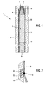
- an arrangement 1 is shown as a detail of a piezoelectric injector with a piezoelectric actuator module, which can be used for example for Nadelhub horrung in the injection system for fuel in an internal combustion engine.
- Piezo elements 3 are part of the piezoelectric actuator 2, which still continues to form the piezoelectric actuator module an actuator base 4 and an actuator head 5 made of steel.
- a mechanical arrangement located vertically below the actuator head 5 can be actuated in such a way that a release of a nozzle opening of the injection system can take place here.
- the arrangement 1 with the piezoactuator 2 is installed in an injector body 8, which is only partially shown here, the fuel being guided past the interior of the injector body on the piezoelectric actuator module.
- This fuel can then be injected for example in a so-called common rail system under the rail pressure mentioned in the introduction or another predetermined pressure in the combustion chamber of an internal combustion engine, not shown here.
- a weldable hose 9 made of plastic, rubber or a mixture of the two substances is present, in particular, the sensitive piezoelectric elements 3 tightly encloses and also with the actuator base 4 and the actuator head 5 is connected via a weld 10 explained in more detail below.
- FIG. 2 the welding 10 on the actuator base 4 or the actuator head 5 can be seen in detail, in which case an annular groove 11, here on the actuator base 5, with a trapezoidal cross-section is present, in which a weldable substance 12 such as rubber, plastic, such as a polymer or Elastomer, or a mixture of these substances is vulcanized.
- a weldable substance 12 such as rubber, plastic, such as a polymer or Elastomer, or a mixture of these substances is vulcanized.
- the piezoelectric actuator 2 is joined together with the actuator base 4, the actuator head 5 after vulcanization of the substance 12. It is then pulled over the piezoelectric actuator 2 of the flexible, weldable tube 9 and welded at one end, for example on the actuator base 4 with the fabric 12 in the groove 11 with a weld 13.
- a vacuum can be generated at the other end, here the actuator head 5, and under the vacuum, the other end of the tube 9 is welded to the local substance 12 in the groove 11 likewise forming a weld 13.
- the tube 9 can also be a shrinking plastic tube which is pressed against the piezoactuator 2 by shrinking.
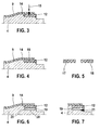
- FIG. 3 is removable, as the substance 12 is vulcanized in a recess 14 of the actuator base 5.
- an arrow 15 is indicated that a cross-linking of the tube 9 is made with the fabric 12, for example by means of a laser welding here.
- FIG. 4 shows in conjunction with FIG. 5 how an enlargement of the bonding surfaces between the fabric 12 and the actuator base 4 made of steel by a triangular tooth contour 16, a rectangular tooth contour 17 or a curved contour 18 can be made. Furthermore, not shown here three-dimensional pyramid contours or cross, transverse or longitudinal grooves are possible.
- FIG. 6 the additional arrangement of a ring carrier 19 between the fabric 12 and the actuator base 4 is shown, which glued, for example, at the areas 20 or according to FIG. 7 can be connected via a weld 21 with the actuator base 4.
- FIGS. 8 to 11 show different versions of cross-linking geometries according to the arrow 15 of the FIG. 3 , where the FIG. 8 a two-lane and the FIG. 9 shows a multi-lane, wedge-shaped and therefore narrow and deep cross-linking geometry 22.
- the FIG. 10 shows a simple and the FIG. 11 a two-lane, approximately rectangular and thus wide and flat cross-linking geometry 23.
- FIG. 12 is a first example of a chambering of the compound or crosslinkable substance 12 in a rectangular groove 24 of the actuator base 4 can be removed and FIGS. 13 and 14 show embodiments of the trapezoidal groove 11 comparable with FIG. 2 at the FIG. 14 slightly rounded at the corners.
Description
Die Erfindung betrifft ein ummanteltes, beispielsweise von flüssigen Medien umströmtes Piezoaktormodul und ein Verfahren zu dessen Herstellung, nach den gattungsgemäßen Merkmalen der nebengeordneten Hauptansprüche.The invention relates to a jacketed, for example, flowed around by liquid media Piezoaktormodul and a method for the production thereof, according to the generic features of the independent main claims.
Es ist an sich bekannt, dass zum Aufbau des zuvor erwähnten Piezoaktormoduls Piezoelemente so eingesetzt werden können, dass unter Ausnutzung des sogenannten Piezoeffekts eine Steuerung des Nadelhubes eines Ventils oder dergleichen vorgenommen werden kann. Piezolagen der Piezoelemente sind aus einem Material mit einer geeigneten Kristallstruktur so aufgebaut, dass bei Anlage einer äußeren elektrischen Spannung eine mechanische Reaktion des jeweiligen Piezoelements erfolgt, die in Abhängigkeit von der Kristallstruktur und der Anlagebereiche der elektrischen Spannung einen Druck oder Zug in eine vorgebbare Richtung darstellt. Derartige aus Piezoelementen gebildete Piezoaktoren eignen sich beispielsweise für Anwendungen, bei denen Hubbewegungen unter hohen Betätigungskräften und hohen Taktfrequenzen ablaufen.It is known per se that for the construction of the aforementioned piezoelectric actuator piezoelectric elements can be used so that by utilizing the so-called piezoelectric effect, a control of the needle stroke of a valve or the like can be made. Piezo layers of the piezoelectric elements are constructed of a material having a suitable crystal structure such that upon application of an external electrical voltage, a mechanical reaction of the respective piezoelectric element takes place, which represents a pressure or tension in a predeterminable direction as a function of the crystal structure and the contact regions of the electrical voltage , Such piezoelectric actuators formed from piezoelectric elements are suitable, for example, for applications in which lifting movements take place under high operating forces and high clock frequencies.
Beispielsweise ist ein solches Piezoaktormodul als Bestandteil eines Piezoinjektors aus der
Solche bekannten Anordnungen werden häufig zur Einbringung von Kraftstoff in direkt einspritzende Dieselmotoren als sogenannte Common Rail Systeme eingesetzt. Bei diesen bekannten Systemen kann dabei der Einspritzdruck auf einfache Weise an die Last und Drehzahl des Verbrennungsmotors angepasst werden.Such known arrangements are often used for introducing fuel into direct-injection diesel engines as so-called common rail systems. In these known systems, the injection pressure can be easily adapted to the load and speed of the internal combustion engine.
Diese Common Rail Injektoren können dabei so aufgebaut werden, dass eine indirekt vom Piezoaktor gesteuerte Düsennadel vorhanden ist, wobei das Piezoaktormodul direkt oder indirekt vom Druck des Kraftstoffs umgeben ist und zwischen der Düsennadel und dem Piezoaktormodul lediglich ein hydraulischer Kopplungsraum vorgesehen ist. Hierbei ist es wichtig, dass der relativ empfindliche Piezoaktor im Inneren eines Haltekörpers vor einer zu großen Druckbelastung bzw. vor Druck- oder Temperaturschwankungen geschützt wird. Zusätzlich ist auch noch ein Schutz vor mechanischem Stoß oder Druck insbesondere hinsichtlich der elektrischen Isolierung und ein Schutz vor Feuchtigkeit (Diesel, Wasser, RM E oder sonstige elektrisch leitende Substanzen), Partikel oder Schwebstoffen notwendig.These common rail injectors can be constructed so that an indirectly controlled by the piezoelectric actuator nozzle needle is present, wherein the piezoelectric actuator is directly or indirectly surrounded by the pressure of the fuel and between the nozzle needle and the piezoelectric actuator only a hydraulic coupling space is provided. It is important that the relatively sensitive piezoelectric actuator is protected in the interior of a holding body from an excessive pressure load or against pressure or temperature fluctuations. In addition, protection against mechanical shock or pressure, in particular with regard to electrical insulation and protection against moisture (diesel, water, RM E or other electrically conductive substances), particles or suspended matter is also necessary.
Um eine elektrische und mechanische Isolierung des Piezoaktors zu erreichen, wird oft eine Ummantelung des Piezoaktors vorgeschlagen. Aus der
Für sich gesehen ist es aus einer Reihe von Anwendungen bekannt, dass mit einer elastischen Kunststoffumspritzung der Piezoaktor zum Beispiel bei einem direkt schaltenden Piezoinjektor, bei dem das Piezoaktormodul direkt dem Hochdruck des Kraftstoffzulaufs ausgesetzt ist, vor den zuvor erwähnten schädlichen Einflüssen geschützt werden kann. Bei diesen direkt schaltenden Piezoinjektoren sitzt zwischen dem Piezoaktormodul und der Düsennadel lediglich ein mechanischer Koppler mit einer hydraulischen Übersetzung, so dass die Nadelbewegung direkt übersetzt der Bewegung des Piezoaktors folgt, wobei hier auch zweistufige Übersetzungen möglich sind.In itself, it is known from a number of applications that, with a flexible plastic extrusion coating, the piezoelectric actuator can be protected against the aforementioned harmful influences, for example in the case of a direct-switching piezo injector in which the piezoelectric actuator module is exposed directly to the high pressure of the fuel feed. In the case of these direct-switching piezoinjectors, only a mechanical coupler with a hydraulic transmission is seated between the piezoelectric actuator module and the nozzle needle, so that the needle movement directly translates into the movement of the piezoactuator, whereby two-stage translations are also possible here.
Bei diesen bekannten Anordnungen besteht immer das Problem der Abdichtung des Beschichtungswerkstoffs, in der Regel Kunststoff, mit den Anbindungsteilen aus Stahl, wie dem Aktorkopf und dem Aktorfuß an den Stirnseiten der Piezoelemente des Piezoaktors. Diese Abdichtung kann meist nur klebend hergestellt werden bzw. es ist die Anbindung auf die Haftfestigkeit des Beschichtungsmaterials auf den Stahlteilen angewiesen.In these known arrangements, there is always the problem of sealing the coating material, usually plastic, with the connecting parts made of steel, such as the actuator head and the actuator base on the end faces of the piezoelectric elements of the piezoelectric actuator. This seal can usually be made only adhesive or it depends on the connection to the adhesion of the coating material on the steel parts.
Die bei einer indirekten Steuerung der Düsennadel bekannten Anordnungen mit einem Piezoaktormodul im Niederdruckbereich des Kraftstoffs weisen Metallhülsenabdichtung auf, die hier als hub- und temperaturausgleichendes Element eingesetzt werden können. Diese Anordnungen sind jedoch nicht auf Anwendungen mit direkter Steuerung der Düsennadel übertragbar. Aufgrund der Konstruktion mit einem Piezoaktormodul im Hochdruckbereich bei der direkten Steuerung würde hier eine starre Metallhülsenabdichtung den hohen Systemdrucken und höheren Hubbewegungen des Piezoaktors unter den zur Verfügung stehenden Platzverhältnissen nicht standhalten.The known in an indirect control of the nozzle needle assemblies with a piezoelectric actuator in the low pressure region of the fuel have metal sleeve seal, which can be used here as a hub and temperature-compensating element. However, these arrangements are not transferable to applications with direct control of the nozzle needle. Due to the design with a piezo actuator module in the high pressure range in the direct control here a rigid metal sleeve seal would not withstand the high system pressures and higher strokes of the piezoelectric actuator under the available space.
Ein Piezoaktormodul mit einer Umhüllung gemäß dem Oberbegriff des Anspruchs 1 ist aus
Die Erfindung geht von einem eingangs beschriebenen Piezoaktormodul mit einem Mehrschichtaufbau von Piezoelementen als Piezoaktor aus, wobei zwischen Piezolagen der Piezoelemente angeordnete Innenelektroden in Richtung des Lagenaufbaus des Piezoelements abwechselnd mit einer unterschiedlichen Polarität einer elektrischen Spannung beaufschlagt sind. Es ist hierzu ein Aktorfuß und ein Aktorkopf aus Stahl vorhanden und es muss zum Schutz vor den umströmenden Medien ein mindestens die Piezoelemente umgebendes elastisches Isolationsmedium vorhanden sein. Erfindungsgemäß ist in vorteilhafter Weise am Aktorfuß und/oder am Aktorkopf mindestens eine ringförmige Nut oder Ausnehmung vorhanden, in die ein sowohl mit dem Stahl als auch mit einem Schlauch oder Hülse aus Kunststoff als Isolationsmedium verbind- oder vernetzbarer Stoff eingebracht ist.The invention is based on a piezoelectric actuator described above with a multi-layer structure of piezoelectric elements as a piezoelectric actuator, wherein between the piezoelectric layers of the piezoelectric elements arranged internal electrodes in the direction of the layer structure of the piezoelectric element are alternately acted upon with a different polarity of an electrical voltage. For this purpose, an actuator base and an actuator head made of steel are present and, to protect against the surrounding media, an elastic insulation medium surrounding at least the piezoelectric elements must be present. According to the invention, at least one annular groove or recess is provided in an advantageous manner on the actuator base and / or on the actuator head into which a substance that can be bound or crosslinked both with the steel and with a hose or sleeve made of plastic as an insulating medium is introduced.
Das Material des Schlauchs oder der Hülse lässt sich nicht direkt mit Stahl hochdruckdicht über die geforderte Lebensdauer verbinden, da diese unterschiedliche Wärmeausdehnungskoeffizienten haben und dadurch Scherkräften auftreten, die zu Schubrissen und zu Undichtheiten führen. Ein solcher Schlauch erzielt die nötige Dichtwirkung gegenüber den Piezoelementen und stellt zusätzlich einen Hub- und Temperaturdehnungsausgleich bei -40 bis +160°C sicher.The material of the hose or sleeve can not be directly connected to steel high pressure-tight over the required life because they have different thermal expansion coefficients and thereby shear forces occur, which lead to shear cracks and leaks. Such a hose achieves the necessary sealing effect with respect to the piezo elements and additionally ensures a stroke and temperature expansion compensation at -40 to + 160 ° C.
Wenn zum Beispiel erfindungsgemäß ein Polymer oder Elastomer als Stoff auf das Stahlteil aufvulkanisiert wird, lässt sich der Schlauch oder die Hülse an den offenen Enden mittels Wärmeeinwirkung, wie UV-Licht, Laser oder Ofenerwärmung, mit dem Stoff verbinden oder vernetzen. Mit der Erfindung können die jeweiligen Materialien speziell nach Ihren Anforderungen ausgelegt werden. Das bedeutet, dass das Polymer oder Elastomer für das Vulkanisieren speziell bezüglich der Wärmedehnung und Haftfestigkeit auf den Stahl abgestimmt werden kann.For example, according to the present invention, when a polymer or elastomer is vulcanized as a fabric to the steel part, the hose or sleeve can be bonded or crosslinked at the open ends by heat, such as UV light, laser or oven heating. With the invention, the respective materials can be designed specifically according to your requirements. This means that the polymer or elastomer for vulcanization can be tailored to the steel specifically with respect to thermal expansion and adhesive strength.
Es ist somit mit einer kostengünstigen, einfachen und dauerhaftes Abdichtung der Schlauchenden ein Medieneintritt über die Lebensdauer des Piezoaktors verhindert.It is thus with a cost-effective, simple and durable sealing of the hose ends prevents media entry over the life of the piezoelectric actuator.
Vorteilhaft weisen die Nuten oder Ausnehmungen einen rechteckigen oder auch einen trapezförmigen, nach innen sich aufweitenden Querschnitt auf, damit der Halt des vorzugsweise auf den Stahl des Kopf- oder Fußteils aufvulkanisierbaren Stoffs im Aktorfuß oder im Aktorkopf verbessert ist.Advantageously, the grooves or recesses have a rectangular or even a trapezoidal, inwardly widening cross-section, so that the support of the preferably aufvulkanisierbaren on the steel of the head or foot part in the actuator base or in the actuator head is improved.
Die Verbindungsflächen der Nuten oder Ausnehmungen am Aktorfuß und/oder am Aktorkopf mit dem Stoff können in vorteilhafter Weise zur Erhöhung der wirksamen Oberfläche eine jeweils korrespondierende Verzahnung aufweisen, die eine dreieckige, rechteckige oder eine Bogen- oder Pyramidenkontur oder Kreuz-, Quer- oder Längsrillen aufweisen. Vorteilhaft ist auch, wenn zwischen dem Aktorfuß und/oder dem Aktorkopf und dem Stoff ein Ringträger mit der jeweiligen Kontur für die Aufnahme des Stoffes auf der Außenseite vorhanden ist.The connecting surfaces of the grooves or recesses on the actuator base and / or on the actuator head with the substance can advantageously have a corresponding toothing for increasing the effective surface, which has a triangular, rectangular or arcuate or pyramidal contour or cross, transverse or longitudinal grooves exhibit. It is also advantageous if a ring carrier with the respective contour for receiving the substance on the outside is present between the actuator base and / or the actuator head and the substance.
Die zuvor erwähnten Verbindungsflächen und Oberflächenstrukturen können in ihrer Form, Dicke und Breite je nach Materialwahl und Platzverhältnissen gestaltet werden.The aforementioned bonding surfaces and surface structures can be designed in their shape, thickness and width depending on the choice of material and space.
Bei einem vorteilhaften Herstellungsverfahren des zuvor beschriebenen Piezoaktors wird zunächst am Aktorfuß und am Aktorkopf vor dem Zusammenbau des Piezoaktormoduls jeweils in eine ringförmige Nut zum Beispiel ein schweißbarer Kunststoff oder eine schweißbare Kunststoff-Gummimischung eingebracht. Der Piezoaktor kann mit dem Aktorfuß und dem Aktorkopf sowie dem dazwischenliegenden Piezoelementen zusammengefügt werden. Es kann dann über den Piezoaktor ein flexibler, schweißbarer Kunststoffschlauch gezogen und an einem Ende verbunden oder vernetzt, insbesondere verschweißt werden.In an advantageous manufacturing method of the piezoelectric actuator described above, a weldable plastic or a weldable plastic-rubber mixture is first introduced on the actuator base and on the actuator head prior to assembly of the piezoelectric actuator in each case in an annular groove. The piezoelectric actuator can be joined together with the actuator foot and the actuator head as well as the piezo elements in between. It can then pulled over the piezoelectric actuator, a flexible, weldable plastic tube and connected at one end or networked, in particular welded.
Gemäß einer Ausführung des Verfahrens wird und nun am anderen Ende ein Vakuum erzeugt und unter dem Vakuum wird das andere Ende des Kunststoffschlauchs mit dem dortigen Kunststoff oder der Kunststoff-Gummimischung in der Nut verschweißt. Die Bildung des Vakuums kann hierbei beispielsweise gleichzeitig eine Dichtheitsprüfung für die erste Schweißnaht und eventuell den Kunststoffschlauch darstellen.According to one embodiment of the method, and now at the other end a vacuum is generated and under the vacuum, the other end of the plastic tube with the there plastic or plastic-rubber compound welded in the groove. For example, the formation of the vacuum may at the same time constitute a leak test for the first weld seam and possibly the plastic hose.
Gemäß einer andern Ausführung des Verfahrens wird ein flexibler, schweißbarer schrumpfender Kunststoffschlauch über den Piezoaktor gezogen und der Kunststoffschlauch wird an einem Ende verschweißt und durch Schrumpfen an den Piezoaktor angedrückt. Das andere Ende des Kunststoffschlauchs kann dann auch hier mit dem dortigen Kunststoff oder der Kunststoff-Gummimischung in der Nut verschweißt werden.According to another embodiment of the method, a flexible, weldable shrinking plastic tube is pulled over the piezoelectric actuator and the plastic tube is welded at one end and pressed by shrinking to the piezoelectric actuator. The other end of the plastic tube can then be welded here with the local plastic or the plastic-rubber compound in the groove.
Es können dabei auch die Merkmale der beiden zuvor erwähnten Varianten kombiniert werden, wobei in allen Fällen leicht sichergestellt werden kann, dass die Beschichtung des Piezoaktors nahezu vollkommen luftleer an der Geometrie des Piezoaktors anliegt, damit sie die eventuell hohen Drücke des umströmenden Mediums abstützen kann und nicht reißt. Ferner kann hiermit auch gewährleistet werden, dass die Beschichtung die Dehnung durch den Hub des Piezoaktors im Betrieb elastisch ausgeglichen werden kann.It can also be the features of the two aforementioned variants are combined, it can be easily ensured in all cases that the coating of the piezoelectric actuator almost completely abreast of the geometry of the piezoelectric actuator so that it can support the possibly high pressures of the flowing medium and do not break. Furthermore, it can also be ensured hereby that the coating can be elastically compensated for the expansion by the stroke of the piezoelectric actuator during operation.
Auf einfache Weise können nach der vollständigen Verschweißung des Kunststoffschlauchs mit dem Kunststoff oder Kunststoff-Gummimischung in den Nuten die überstehende Enden des Kunststoffschlauchs mechanisch mit einem geeigneten Scheidewerkzeug entfernt werden.In a simple way, after the complete welding of the plastic tube with the plastic or plastic-rubber mixture in the grooves, the protruding ends of the plastic tube can be removed mechanically with a suitable cutting tool.
Die Erfindung ist vor allem deswegen vorteilhaft zu realisieren, da bei der Verwendung von Stahlbauteilen für den Aktorfuß und den Aktorkopf sich relativ leicht gute Stahl-Kunststoffverbindungen herstellen lassen, die aus der Vulkanisationstechnik für sich gesehen bekannt sind. Da ein solches Verfahren bei einer Beschichtung des Piezoelements durch die relativ hohen Vulkanisiertemperaturen nachteilig ist, kann mit der erfindungsgemäßen separaten Anbindung am Aktorfuß und/oder am Aktorkopf dieser Vorgang getrennt von der Montage des Piezoaktors vorgenommen werden.The invention is above all advantageous to realize because when using steel components for the Aktorfuß and the actuator head can be relatively easily produce good steel-plastic compounds, which are known from the vulcanization known. Since such a method is disadvantageous in a coating of the piezoelectric element by the relatively high vulcanizing temperatures, this process can be carried out separately from the assembly of the piezoelectric actuator with the inventive separate connection to the actuator base and / or on the actuator head.
Weiter vorteilhafte Ausgestaltungen der Erfindung sind in den Unteransprüchen angegeben.Further advantageous embodiments of the invention are specified in the subclaims.
Ausführungsbeispiele des erfindungsgemäßen Piezoaktormoduls werden anhand der Zeichnungen erläutert. Es zeigen:
- Figur 1
- einen Schnitt durch Teile eines Piezoinjektors mit einem ummantel- ten Piezoaktormodul mit einem Aktorkopf, Piezoelementen als Pie- zoaktor und einem Aktorfuß in einem Schlauch aus Kunststoff,
Figur 2- eine detaillierte Ansicht der Verbindungsstelle zwischen dem Schlauch nach der
Figur 1 und einem mit dem Schlauch verbind- o- der vernetzbaren Stoff in einer Nut des Aktorfußes, Figur 3- eine detaillierte Ansicht der Verbindungsstelle nach der
Figur 1 mit einem verbind- oder vernetzbaren Stoff in einer Ausnehmung des Ak- torfußes und einer Schweißstelle, Figur 4- eine Abwandlung der Darstellung nach der
Figur 3 Figur 5- mögliche Verzahnungskonturen für die Ausführung nach der
Figur 4 Figur 6- eine Abwandlung der Darstellung nach der
Figur 4 Figur 7- eine Schweißverbindung zwischen dem Ringträger nach der
Figur 6 und dem Aktorfuß, Figuren 8bis 11- verschiedene Ausführungen der Schweißstelle nach der
Figur 3 und Figuren 12bis 14- verschiedene Ausführungen der Nuten mit einer Kammerung des verbind- oder vernetzbaren Stoffs in der Nut des Aktorfußes.
- FIG. 1
- 3 shows a section through parts of a piezo injector with a coated piezoelectric actuator module with an actuator head, piezo elements as a piezoelectric actuator and an actuator foot in a hose made of plastic,
- FIG. 2
- a detailed view of the junction between the hose after the
FIG. 1 and a substance which can be crosslinked or crosslinked with the tube in a groove of the actuator base, - FIG. 3
- a detailed view of the junction after the
FIG. 1 with a bondable or cross-linkable substance in a recess of the anode and a weld, - FIG. 4
- a modification of the representation after the
FIG. 3 with a toothing contour between the substance in the recess and the actuator foot, - FIG. 5
- possible toothing contours for the execution after the
FIG. 4 . - FIG. 6
- a modification of the representation after the
FIG. 4 with a ring carrier, - FIG. 7
- a welded joint between the ring carrier after the
FIG. 6 and the actuator foot, - FIGS. 8 to 11
- different versions of the weld after the
FIG. 3 and - FIGS. 12 to 14
- various designs of the grooves with a chambering of the bondable or crosslinkable substance in the groove of the actuator base.
In
Die Anordnung 1 mit dem Piezoaktor 2 ist in einem hier nur teilweise gezeigten Injektorkörper 8 eingebaut, wobei der Kraftstoff durch den Innenraum des Injektorkörpers am Piezoaktormodul vorbeigeführt wird. Dieser Kraftstoff kann dann beispielsweise bei einem sogenannten Common Rail System unter dem in der Beschreibungseinleitung erwähnten Raildruck oder einem anderen vorgebbaren Druck in den Brennraum eines hier nicht dargestellten Verbrennungsmotors injiziert werden.The arrangement 1 with the
Um den Piezoaktor 2 vor dem umströmenden Kraftstoff und vor sonstigen schädlichen Einwirkungen zu schützen, ist ein schweißbarer Schlauch 9 aus Kunststoff, Gummi oder einem Gemisch der beiden Stoffe vorhanden, der insbesondere die empfindlichen Piezoelemente 3 fest umschließt und außerdem mit dem Aktorfuß 4 und dem Aktorkopf 5 über eine unten noch näher erläuterte Verschweißung 10 verbunden ist.In order to protect the
Aus
Zur Herstellung dieses zuvor beschriebenen Piezoaktormoduls wird der Piezoaktor 2 nach dem Einvulkanisieren des Stoffes 12 mit dem Aktorfuß 4, dem Aktorkopf 5 zusammengefügt. Es wird dann über den Piezoaktor 2 der flexible, schweißbare Schlauch 9 gezogen und an einem Ende, beispielsweise am Aktorfuß 4 mit dem Stoff 12 in der Nut 11 mit einer Schweißnaht 13 verschweißt.To produce this piezoelectric actuator described above, the
Gemäß einer ersten Variante kann am anderen Ende, hier der Aktorkopf 5, ein Vakuum erzeugt werden und unter dem Vakuum wird das andere Ende des Schlauchs 9 mit dem dortigen Stoff 12 in der Nut 11 ebenfalls unter Bildung einer Schweißnaht 13 verschweißt. Andererseits kann der Schlauch 9 auch ein schrumpfender Kunststoffschlauch sein, der durch Schrumpfen an den Piezoaktor 2 angedrückt wird.According to a first variant, a vacuum can be generated at the other end, here the
Aus
In
Aus
Claims (14)
- Piezo-actuator module with a multi-layer set-up of piezo-elements (3) as a piezo-actuator (2), inner electrodes arranged between piezo-layers of the piezoelements (3) being acted upon alternately with a different polarity of an electrical voltage in the direction of the layered set-up of the piezo-actuator (2), with an actuator foot (4) and an actuator head (5) consisting of steel, and with an insulation medium which surrounds at least the piezo-elements (3) and is elastic within predetermined limits, and with at least one annular groove (11; 24) or recess (14) on the actuator foot (4) and/or on the actuator head (5), characterized in that a material (12) connectable to or cross-linkable with the insulation medium is introduced into these grooves or recesses, and in that a flexible hose (9), as insulation medium, lies over the piezoelements (3) and at least over the grooves (11; 24) or recesses (14) having the material (12) and is connected to or cross-linked with the material (12) in the grooves (11; 24) or recesses (14).
- Piezo-actuator module according to Claim 1, characterized in that the material (12) is vulcanised into the grooves (11; 24) or recesses (14).
- Piezo-actuator module according to Claim 1 or 2, characterized in that the material (12) and/or the hose (9) is a flexible plastic, preferably a polymer or elastomer, a rubber or a mixture of the two materials.
- Piezo-actuator module according to Claim 3, characterized in that the hose (9) is formed from a plastic shrinkable under the action of heat.
- Piezo-actuator module according to one of the preceding claims, characterized in that the grooves (11; 24) or recesses (14) have a rectangular or, at least on one side, a trapezoidal cross section widening inwards.
- Piezo-actuator module according to one of the preceding claims, characterized in that the surfaces of connection of the grooves (11; 24) or recesses (14) on the actuator foot (4) and/or on the actuator head (5) to the material (12) have, in order to increase the effective surface, an in each case matching toothing contour (6, 17, 18) having a triangular, rectangular or arcuate or pyramidal contour or cross, transverse or longitudinal flutes.
- Piezo-actuator module according to Claim 5 or 6, characterized in that a ring carrier (19) is present between the actuator foot (4) and/or the actuator head (5) and the material (12).
- Piezo-actuator module according to Claim 7, characterized in that the ring carrier (19) is welded at a weld seam (21) or adhesively bonded or soft-soldered to the actuator foot (4) and/or the actuator head (5).
- Piezo-actuator according to one of the preceding claims, characterized in that the flexible hose (9) is cross-linked, preferably welded, to the material (12) in the grooves (11; 24) or recesses (14) by means of two-track or multi-track wedge-shaped, rectangular or trapezoidal cross-linking geometries (22; 23).
- Method for producing a piezo-actuator module according to one of the preceding claims, characterized in that the material (12) connectable or cross-linkable to the hose (9) is introduced into the annular groove (11; 24) or recess (14) in each case on the actuator foot (4) and on the actuator head (5) prior to assembly, in that the piezo-actuator (2) is joined together with the actuator foot (4) and the actuator head (5), in that the flexible hose (9) is drawn as insulation medium over the piezo-actuator (2) and at least partially over the actuator foot (4) and the actuator head (5), and in that the hose (9) is connected or cross-linked to the material (12) first at one end and then at the other end under the action of heat.
- Method for producing a piezo-actuator module according to Claim 10, characterized in that a flexible shrinking hose (9) is drawn over the piezo-actuator (2) and at least partially over the actuator foot (4) and the actuator head (5), in that the hose (9) is welded at one end and is pressed by shrinkage onto the piezo-actuator (2), and in that the other end of the hose (9) is then welded to the material (12) located there in the groove (11; 24) or recess (14).
- Method according to Claim 10 or 11, characterized in that a vacuum is generated at the other end of the hose (9), and in that the other end of the shrinking hose (9) is welded under the vacuum to the material (12) located there in the groove (11; 24) or recess (14).
- Method according to one of Claims 10 to 12, characterized in that, after the hose (9) has been welded completely to the material (12) in the grooves (11; 24) or recesses (14), projecting ends of the hose (9) are removed mechanically.
- Use of a piezo-actuator module according to one of the preceding claims, characterized in that the piezo-actuator module is an integral part of a piezo-injector for an injection system for fuel in an internal combustion engine, the fuel flowing around the hose (9).
Applications Claiming Priority (3)
| Application Number | Priority Date | Filing Date | Title |
|---|---|---|---|
| DE102006018703 | 2006-04-21 | ||
| DE102007011315A DE102007011315A1 (en) | 2006-04-21 | 2007-03-08 | Piezoelectric actuator with a sheath and a method for its production |
| PCT/EP2007/053753 WO2007122149A1 (en) | 2006-04-21 | 2007-04-18 | Piezoelectric actuator module having a sheath, and a method for producing said module |
Publications (2)
| Publication Number | Publication Date |
|---|---|
| EP2013922A1 EP2013922A1 (en) | 2009-01-14 |
| EP2013922B1 true EP2013922B1 (en) | 2009-07-01 |
Family
ID=38266248
Family Applications (1)
| Application Number | Title | Priority Date | Filing Date |
|---|---|---|---|
| EP07728215A Expired - Fee Related EP2013922B1 (en) | 2006-04-21 | 2007-04-18 | Piezoelectric actuator module having a sheath, and a method for producing said module |
Country Status (5)
| Country | Link |
|---|---|
| US (1) | US7872398B2 (en) |
| EP (1) | EP2013922B1 (en) |
| JP (1) | JP5108871B2 (en) |
| DE (2) | DE102007011315A1 (en) |
| WO (1) | WO2007122149A1 (en) |
Families Citing this family (2)
| Publication number | Priority date | Publication date | Assignee | Title |
|---|---|---|---|---|
| JP2009527118A (en) * | 2006-02-14 | 2009-07-23 | デルファイ・テクノロジーズ・インコーポレーテッド | Barrier coating for piezoelectric devices |
| DE102011085560A1 (en) * | 2011-11-02 | 2013-05-02 | Robert Bosch Gmbh | fuel injector |
Family Cites Families (12)
| Publication number | Priority date | Publication date | Assignee | Title |
|---|---|---|---|---|
| JPS60104762A (en) * | 1983-11-10 | 1985-06-10 | Nippon Soken Inc | Electro-distorsion actuator and fuel injection valve |
| DE3850641T2 (en) | 1987-12-02 | 1994-10-27 | Nec Corp | Structure for sealing an electrostrictive element. |
| JPH05226722A (en) * | 1992-01-20 | 1993-09-03 | Nec Corp | Simply packaged electrostrictive effect device |
| DE19753930A1 (en) * | 1997-12-05 | 1999-06-10 | Ceramtec Ag | Process for attaching external electrodes to solid state actuators |
| DE10025997A1 (en) * | 2000-05-25 | 2001-12-06 | Bosch Gmbh Robert | Piezo actuator |
| DE10230032A1 (en) * | 2002-07-04 | 2004-01-22 | Daimlerchrysler Ag | Piezoelectric actuator for flowing media and use of a corresponding piezoelectric actuator |
| EP1574702B1 (en) * | 2004-03-11 | 2006-06-07 | Delphi Technologies, Inc. | A method of assembling a fuel injector |
| US7145282B2 (en) * | 2004-07-15 | 2006-12-05 | Delphi Technologies, Inc. | Actuator |
| DE102005015256A1 (en) * | 2005-04-04 | 2006-10-05 | Robert Bosch Gmbh | Piezoelectric actuator with labyrinth seal for use in fuel injection valve, has plastic sealing formed with projections that are inserted and completely fill circulating grooves formed on head or base portion of piezoelectric component |
| DE102005039553A1 (en) * | 2005-08-22 | 2007-03-01 | Robert Bosch Gmbh | Piezo actuator with a self-centering plug connection |
| EP1854996B1 (en) * | 2006-05-08 | 2008-11-05 | Continental Automotive GmbH | Piezoelectric actuator, method for the production of a piezoelectric actuator and injection system with such an actuator |
| DE102007018039A1 (en) * | 2006-09-14 | 2008-03-27 | Robert Bosch Gmbh | Piezo actuator module for common rail injection system, has casing attached to connection units in region of front surfaces of piezo actuator and/or actuator head and/or actuator base in force fit and/or form fit manner |
-
2007
- 2007-03-08 DE DE102007011315A patent/DE102007011315A1/en not_active Withdrawn
- 2007-04-18 WO PCT/EP2007/053753 patent/WO2007122149A1/en active Application Filing
- 2007-04-18 DE DE502007000997T patent/DE502007000997D1/en active Active
- 2007-04-18 JP JP2009505874A patent/JP5108871B2/en not_active Expired - Fee Related
- 2007-04-18 US US12/294,282 patent/US7872398B2/en not_active Expired - Fee Related
- 2007-04-18 EP EP07728215A patent/EP2013922B1/en not_active Expired - Fee Related
Also Published As
| Publication number | Publication date |
|---|---|
| WO2007122149A1 (en) | 2007-11-01 |
| EP2013922A1 (en) | 2009-01-14 |
| JP2009534826A (en) | 2009-09-24 |
| US7872398B2 (en) | 2011-01-18 |
| JP5108871B2 (en) | 2012-12-26 |
| DE102007011315A1 (en) | 2007-10-25 |
| US20090200897A1 (en) | 2009-08-13 |
| DE502007000997D1 (en) | 2009-08-13 |
Similar Documents
| Publication | Publication Date | Title |
|---|---|---|
| EP1906464B1 (en) | Piezo actuator with a jacket for placing in a piezo injector | |
| EP1901360B1 (en) | Piezo actuator module with a cladded piezo actuator | |
| EP1920476B1 (en) | Arrangement with a piezo actuator | |
| EP1714024B1 (en) | Fuel system part with a cable leadthrough | |
| EP2013922B1 (en) | Piezoelectric actuator module having a sheath, and a method for producing said module | |
| DE102006022997A1 (en) | piezo actuator | |
| EP2058873B1 (en) | Piezo actuator and piezo actuator module with a protective coating system | |
| DE102005045229A1 (en) | Arrangement with a piezoelectric actuator and a method for its production | |
| EP2013923B1 (en) | Piezoactuator with a casing | |
| DE102008001524A1 (en) | Piezoelectric actuator module for actuating fuel injection valve closing body of air-compressing, auto-ignition internal combustion engine, has bellows including metallic layer directly attached on outer side of polymer tube | |
| EP1912265B1 (en) | Actuator module with a cladded piezo actuator | |
| EP1973176A2 (en) | Method and device for manufacturing a piezo-electric actuator module with an encased piezo actuator and a piezo actuator module | |
| EP1820960B1 (en) | Fuel injector | |
| EP1909339B1 (en) | Actuator module having an enshrouded piezo actuator | |
| DE102005039567A1 (en) | Arrangement with a piezoelectric actuator and a method for its production | |
| EP2034532A1 (en) | Piezoelectric actuator module with a protective layer system and method for its manufacture | |
| DE102005039558B4 (en) | Arrangement with a piezoelectric actuator and a method for its production | |
| EP1919004B1 (en) | Piezo actuator module or piezo actuator with a cladded protection layer system | |
| DE102006054700A1 (en) | Actuator module for piezo-injector, has piezo-actuator including casing with metal components in area of connection of rubber element at actuator head and actuator base, where rubber element is provided in area of piezo-elements | |
| WO2007023034A2 (en) | Arrangement with a piezoactuator and a method for production thereof | |
| DE102008001525A1 (en) | Piezoelectric actuator module | |
| DE102008004246A1 (en) | Piezoelectric actuator module for fuel injection system of air-compressing, self-igniting internal-combustion engine, has balancing channel of adapter piece connecting interspace with environment and filled with extreme pressure additive | |
| EP2317578A2 (en) | Piezoelectric actuator |
Legal Events
| Date | Code | Title | Description |
|---|---|---|---|
| PUAI | Public reference made under article 153(3) epc to a published international application that has entered the european phase |
Free format text: ORIGINAL CODE: 0009012 |
|
| 17P | Request for examination filed |
Effective date: 20081121 |
|
| AK | Designated contracting states |
Kind code of ref document: A1 Designated state(s): AT BE BG CH CY CZ DE DK EE ES FI FR GB GR HU IE IS IT LI LT LU LV MC MT NL PL PT RO SE SI SK TR |
|
| AX | Request for extension of the european patent |
Extension state: AL BA HR MK RS |
|
| GRAP | Despatch of communication of intention to grant a patent |
Free format text: ORIGINAL CODE: EPIDOSNIGR1 |
|
| RIC1 | Information provided on ipc code assigned before grant |
Ipc: H01L 41/053 20060101AFI20090227BHEP Ipc: H01L 41/083 20060101ALN20090227BHEP Ipc: F02M 51/06 20060101ALI20090227BHEP |
|
| GRAS | Grant fee paid |
Free format text: ORIGINAL CODE: EPIDOSNIGR3 |
|
| DAX | Request for extension of the european patent (deleted) | ||
| RBV | Designated contracting states (corrected) |
Designated state(s): DE ES FR GB IT |
|
| GRAA | (expected) grant |
Free format text: ORIGINAL CODE: 0009210 |
|
| AK | Designated contracting states |
Kind code of ref document: B1 Designated state(s): DE ES FR GB IT |
|
| REG | Reference to a national code |
Ref country code: GB Ref legal event code: FG4D Free format text: NOT ENGLISH |
|
| REF | Corresponds to: |
Ref document number: 502007000997 Country of ref document: DE Date of ref document: 20090813 Kind code of ref document: P |
|
| PG25 | Lapsed in a contracting state [announced via postgrant information from national office to epo] |
Ref country code: ES Free format text: LAPSE BECAUSE OF FAILURE TO SUBMIT A TRANSLATION OF THE DESCRIPTION OR TO PAY THE FEE WITHIN THE PRESCRIBED TIME-LIMIT Effective date: 20091012 |
|
| PLBE | No opposition filed within time limit |
Free format text: ORIGINAL CODE: 0009261 |
|
| STAA | Information on the status of an ep patent application or granted ep patent |
Free format text: STATUS: NO OPPOSITION FILED WITHIN TIME LIMIT |
|
| 26N | No opposition filed |
Effective date: 20100406 |
|
| PG25 | Lapsed in a contracting state [announced via postgrant information from national office to epo] |
Ref country code: IT Free format text: LAPSE BECAUSE OF NON-PAYMENT OF DUE FEES Effective date: 20100418 |
|
| GBPC | Gb: european patent ceased through non-payment of renewal fee |
Effective date: 20110418 |
|
| PG25 | Lapsed in a contracting state [announced via postgrant information from national office to epo] |
Ref country code: GB Free format text: LAPSE BECAUSE OF NON-PAYMENT OF DUE FEES Effective date: 20110418 |
|
| REG | Reference to a national code |
Ref country code: FR Ref legal event code: PLFP Year of fee payment: 10 |
|
| REG | Reference to a national code |
Ref country code: FR Ref legal event code: PLFP Year of fee payment: 11 |
|
| REG | Reference to a national code |
Ref country code: FR Ref legal event code: PLFP Year of fee payment: 12 |
|
| PGFP | Annual fee paid to national office [announced via postgrant information from national office to epo] |
Ref country code: IT Payment date: 20190419 Year of fee payment: 13 |
|
| PGFP | Annual fee paid to national office [announced via postgrant information from national office to epo] |
Ref country code: FR Payment date: 20190423 Year of fee payment: 13 |
|
| PGFP | Annual fee paid to national office [announced via postgrant information from national office to epo] |
Ref country code: DE Payment date: 20190627 Year of fee payment: 13 |
|
| REG | Reference to a national code |
Ref country code: DE Ref legal event code: R119 Ref document number: 502007000997 Country of ref document: DE |
|
| PG25 | Lapsed in a contracting state [announced via postgrant information from national office to epo] |
Ref country code: DE Free format text: LAPSE BECAUSE OF NON-PAYMENT OF DUE FEES Effective date: 20201103 Ref country code: FR Free format text: LAPSE BECAUSE OF NON-PAYMENT OF DUE FEES Effective date: 20200430 |
|
| PG25 | Lapsed in a contracting state [announced via postgrant information from national office to epo] |
Ref country code: IT Free format text: LAPSE BECAUSE OF NON-PAYMENT OF DUE FEES Effective date: 20200418 |