EP2013546B1 - Hebevorrichtung - Google Patents
Hebevorrichtung Download PDFInfo
- Publication number
- EP2013546B1 EP2013546B1 EP07755902.9A EP07755902A EP2013546B1 EP 2013546 B1 EP2013546 B1 EP 2013546B1 EP 07755902 A EP07755902 A EP 07755902A EP 2013546 B1 EP2013546 B1 EP 2013546B1
- Authority
- EP
- European Patent Office
- Prior art keywords
- lift
- ceiling
- floor
- rail
- attic
- Prior art date
- Legal status (The legal status is an assumption and is not a legal conclusion. Google has not performed a legal analysis and makes no representation as to the accuracy of the status listed.)
- Not-in-force
Links
Images

Classifications
-
- B—PERFORMING OPERATIONS; TRANSPORTING
- B66—HOISTING; LIFTING; HAULING
- B66F—HOISTING, LIFTING, HAULING OR PUSHING, NOT OTHERWISE PROVIDED FOR, e.g. DEVICES WHICH APPLY A LIFTING OR PUSHING FORCE DIRECTLY TO THE SURFACE OF A LOAD
- B66F7/00—Lifting frames, e.g. for lifting vehicles; Platform lifts
- B66F7/10—Lifting frames, e.g. for lifting vehicles; Platform lifts with platforms supported directly by jacks
- B66F7/12—Lifting frames, e.g. for lifting vehicles; Platform lifts with platforms supported directly by jacks by mechanical jacks
- B66F7/14—Lifting frames, e.g. for lifting vehicles; Platform lifts with platforms supported directly by jacks by mechanical jacks screw operated
-
- B—PERFORMING OPERATIONS; TRANSPORTING
- B66—HOISTING; LIFTING; HAULING
- B66B—ELEVATORS; ESCALATORS OR MOVING WALKWAYS
- B66B9/00—Kinds or types of lifts in, or associated with, buildings or other structures
-
- B—PERFORMING OPERATIONS; TRANSPORTING
- B66—HOISTING; LIFTING; HAULING
- B66F—HOISTING, LIFTING, HAULING OR PUSHING, NOT OTHERWISE PROVIDED FOR, e.g. DEVICES WHICH APPLY A LIFTING OR PUSHING FORCE DIRECTLY TO THE SURFACE OF A LOAD
- B66F7/00—Lifting frames, e.g. for lifting vehicles; Platform lifts
- B66F7/28—Constructional details, e.g. end stops, pivoting supporting members, sliding runners adjustable to load dimensions
Definitions
- This invention related generally to a lift apparatus for raising or lowering objects from one floor in a building to another floor in a building. More specifically, it relates to an apparatus when not in use is stored in the attic and can be deployed to the floor of the room below the attic to move objects from the floor below to the attic or to move objects from the attic to the room below.
- Attic an area between the roof and the ceiling of the room situated below that part of the roof. Attics are sometimes used for storage of objects. Moreover, access must be provided from the living or working areas of a building to the attic in the event of a need to make repairs, to check on electrical wiring or heating and air conditioning ducts, and so on. Consequently, there is ordinarily some means of access provided for a user of a building to this attic space.
- the most common access to the attic storage area consists of an opening in a ceiling.
- the opening is usually concealed by a trap door apparatus.
- a trap door apparatus Built into the trap door is a folding ladder. Therefore, to gain access to the attic, the trap door is pulled down, usually by a chain or a rope, which allows one access to the folded ladder.
- the ladder is unfolded with the bottom of the ladder now resting on the floor of the room below the trap door in the opening in the ceiling. One may then walk up the ladder through the opening into the attic area.
- the trap door is usually closed by a spring loaded hinge, which holds the trap door into the closed position until someone pulls on the chain or the rope that extends from the trap door into the room below.
- An alternative to folding stairways is a unitary stairway, such as that described by Harmon in U.S. Pat. No. 3,985,202 .
- This stairway employs hydralulic means to move the stairway from a horizontal inoperative position to an inclined operative position.
- the ladder means balancing one's feet on narrow rungs on a narrow ladder that is steeply angled to the floor on which the ladder rests. This makes it difficult to safely carry boxes of any size or weight from the living area into the attic area. Consequently, most attics are used for storage of such relatively light items as Christmas decorations, seasonal items, small boxes of clothes, empty luggage and other light weight items. Attics are rarely used for storage of substantial items such as household furniture, appliances, televisions, or other large or heavy items. The attic area is useable only by people who are capable of using a narrow, steep ladder. This excludes almost anyone with balance problems, people with bad knees, or people who have difficulty negotiating stairs.
- a variety of expedients have been proposed as an alternative to the folding stairs.
- the most common expedient employs a framework attached to wood joists that may form a part of the ceiling of the room above the ceiling opening to the attic area.
- Mounted on this framework is a winch and cable drum attached at four corners to a lift platform. The winch can then be employed to raise or lower the lift platform.
- a winch and cable drum attached at four corners to a lift platform.
- the winch can then be employed to raise or lower the lift platform.
- the lift platform When not in use, the lift platform is ordinarily kept in the ceiling above the room in which the guide rail is mounted. This closes off the ceiling opening and prevents any inadvertent falls through the ceiling opening and also closes off what would otherwise be an unsightly hole in the ceiling.
- Patent #3,478,904 proposes a folding device with a moveable lift platform mounted for slidable movement on the folding rails of the device. The lift platform is raised and lowered by cable winches mounted within the airplane.
- a somewhat similar device is seen in Molter et al., Patent #3,861,542 .
- the device folds into and deploys from a cargo bay in an airplane.
- Within the device is a cable-like device to raise and lower a platform on which a cargo container may be placed when the cargo container is in position to be moved into the airplane itself.
- the device hangs from the side of the airplane and is supported by the airplane structure.
- Similar type devices seen for cargo handling in airplanes are seen in Lang, Patent #3,952,974 , Carter et al., Patent #4,586,684 , and Goon, Patent #5,076,515 .
- the device should operate automatically and provide for a powered lift of people and/or goods from one area to another.
- the device should be usable for existing homes with a trap door in the ceiling and should be usable in new construction. It should be built with a fail-safe safety feature so that should power fail or a part of the device break, it will not result in a sudden drop of goods or a person from the ceiling to the floor. It should require no physical effort to open, operate, utilize, or close. It should place no operating weight on the ceiling. When not in use, it should occupy no residential floor space nor should it be a permanent part of the residential area. It should meet existing building code requirements and existing safety codes. It should be useable by people with physical handicaps or with an inability to use prior art folding ladders.
- the invention consists of a rigid rail.
- One end of the rail is in proximity to a trap door which rotates for opening into the room below the attic floor on which the rigid rail is mounted.
- the rail is mounted for slidable movement into the opening created by the trap door in the ceiling.
- At the end of the rail opposite from the trap door there is a lift platform of a size and shape to allow it to fit through the opening created by the trap door in the ceiling of the room below the attic in which the rigid rail is mounted.
- the rail is mounted for slidable rotatable movement. As the trap door begins to open, the rail is slid into the opening created by the trap door and will begin to move along the line of the now opening trap door.
- the end of the rigid rail mounted in proximity to the door begins to extend into the room below.
- the rigid rail begins to tilt off a horizontal orientation toward a vertical orientation.
- the rigid rail continues its movement into the room below.
- the angle of the trap door moves toward the vertical, so does the rigid rail.
- the rigid rail When the door is fully open and in a vertical orientation perpendicular to the floor below, the rigid rail now assumes a largely vertical orientation perpendicular to the floor below.
- the end of the rigid rail, which was mounted in proximity to the trap door now extends to and rests upon the floor of the room below. The weight of the rigid rail and of the lift platform is supported by the floor.
- the lift platform can now be lowered to the floor with the weight of the lift platform supported by the floor by the floor end of the rigid rail.
- the lift platform can be raised and lowered by a number of expedients, including cables or a screw drive or worm gear.
- the electric motor can be used to raise and lower the lift platform from the floor of the room below into the attic space. Because the lift platform is mounted on a rigid rail, it is easy to maintain at a vertical orientation.
- the lift platform can move at a comfortable speed for someone standing in the lift platform. It can be designed to move several hundreds of pounds of boxes or items using the electric motor.
- the electric motor can be controlled by a remote device.
- a person can stand on the lift platform as it goes up and down or a person can remain on the floor below the lift platform while a second person remains in the attic. This maximizes the amount of weight that can be moved on the lift platform from the room below to the attic.
- the ceiling opening and the lift platform can be used to move relatively large items, such as chairs, appliances, televisions, and the like. It could be used in conjunction with hand carts or other devices to move relatively heavy bulky items.
- the lift apparatus itself may be made of appropriate lightweight aluminum or other materials so that the lift apparatus can be mounted on standard ceiling joists without the necessity of providing any extra bracing for support.
- the rigid rail rests on the floor which supports the lift rail and the weight of items moved during the operation of the lift apparatus. This means that the lift apparatus can be installed to existing homes without making any substantial modifications either to the ceiling area where the apparatus is mounted or to the floor where the rigid rail would be supported during use.
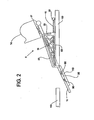
- FIG 1 shows an embodiment of the lift apparatus (5) seen from the side in partial cut-a-way.
- the lift apparatus (5) is shown in an extended position ready for use.
- the lift apparatus (5) is mounted above and on the ceiling (100).
- the lift apparatus (5) has several major mechanical parts.
- the lift rail (10) is extended and resting on the floor (200).
- This bumper will serve both to stabilize the lift rail (10) when resting on the floor and to distribute the weight of the lift rail and of its load in the platform (14) when in use.
- the bumper will be of a standard design. No particular bumper design is shown in Figure 1 .
- the space between the floor (200) and the ceiling (100) is 10 feet. It will readily appreciated that the lift apparatus (5) could be adopted to different sized ceilings.
- Figure 1 exemplar dimensions are shown in order to give a better idea of the dimensions required for a practical embodiment the lift apparatus (5). Shown in proximity to the floor (200) is a lift platform (14) in solid lines. The lift platform (14) is mounted for longitudinal movement on the lift rail (10). Once the lift rail (10) is deployed to the floor, the platform (14) (shown in dotted lines in Figure 1 ) will move from its storage position at the lift rail motor (17) end of the lift rail (10), in the direction shown by the arrow, to the point the lift platform (14) is in proximity to the floor (200).
- An acme screw (15) translates a rotational movement provided by the lift rail motor (17) into linear motion of the lift platform (14).
- a screw drive of some kind is a preferred means of raising and lowering the lift platform (14).
- a screw drive provides a mechanical advantage, thus reducing the size and torque required of the lift rail motor (17).
- appropriately designing an acme screw drive (15) provides a self-locking function. The self-locking function is achieved by selecting a nut (not shown) to ride on the acme screw drive (15) with an efficiency below 35 %.
- the lift platform (14) is expected to move relatively slowly from the position on the floor (200) (as shown) until it is raised to the ceiling 10 feet above as shown by the lift platform (14) shown in dotted lines.
- the relatively slow linear movement of the lift platform (14) along the acme screw drive (15) reassures a user and also avoids problems associated with a higher efficiency nut such as back driving.
- the lift rail motor (17) will ordinarily be operated by a radio actuated remote control (not shown) which will turn the lift rail motor (17) on and off and to control the direction it drives the acme screw drive (15) to raise or lower the lift platform (14).
- the lift rail (10) mounts on at least one positioning guide (20).
- the positioning guide (20) has a positioning slot (23).
- guide rollers (19) (seen in Figure 2 ) are mounted within the positioning slot (23).
- the positioning motor (50) uses a positioning acme drive (52).
- the positioning acme drive (52) rotates. As the positioning acme screw rotates it moves a nut (not shown) along the positioning acme drive (52).
- the acme drive (52) may rotate in one direction or reverse to rotate in the other direction to move the screw longitudinally along the length of the positioning acme drive (52).
- Rotationally mounted on the nut is a control arm (53).
- One end of the control arm (53) is positioned within the positioning slot (23) and attached to the lift rail (10). Consequently, as the positioning acme drive (52) rotates, it moves the control arm (53) along the acme drive (52).
- the control arm (53) either pulls or pushes the lift rail (10) as it slides along the positioning slot (23) in the positioning guide (20).
- a lift control trolley (95) may be mounted on the trap door (110). This will be explained in more detail in other drawings.
- the lift control trolley (95) may provide a guide for deployment of the lift rail (10).
- the lift control trolley (95) may also use controlled rotation bearings (90) to further assure a safe deployment of the lift rail (10) from the storage position above the floor to a fully deployed use position, as seen in Figure 1 , where the lift rail (10) is supported by the floor (200). Because the positioning acme drive (52) itself provides a "fail-safe" deployment of the lift rail (10) and because the positioning guide (20) also provides stability for the lift rail (10) during deployment, it is not anticipated that a lift control trolley (95) may be used where the positioning acme drive (52) is employed. However, the lift control trolley (95) does provide an extra element of safety and control for the lift rail (10).
- the lift control trolley (95) is shown in Figure 1 deployed on the trap door (110).
- the positioning of the lift rail (10) from a resting position in the ceiling (100) to an in-use position on the floor (200) will be shown in more detail in other drawings.
- the positioning guide (20), guide rollers (19), positioning acme drive (52), and positioning motor (50) assures that the lift rail (10) will be safely raised and lowered into position.
- a second acme drive such as the positioning acme drive (52) along with a second motor such as the positioning motor (50) adds to the overall expense of the lift apparatus (6) and it is possible as will be seen in later drawings, to provide for safe and efficient deployment of the lift rail (10) without the additional expense of the positioning acme drive (52) and the positioning motor (50).
- Figure 1 shows illustrative dimensions in English units.
- the ceiling to floor height is 10 feet (3.05 meters).
- the overall height of the lift rail is 13 feet (3.96 meters).
- the ceiling door (110) is four feet, six inches (1.37 meters).
- the positioning guide (20) is seven feet, two inches (2.18 meters) in length while it is two feet four and one-eighth inches in height (.714 meters).
- the total length of the positioning acme drive (52) along with the positioning motor (50) is nine feet, three and three-sixteenths inches (2.82 meters). These dimensions are necessarily conformed for the ceiling height of 10 feet (3.05 meters).
- a different ceiling height will necessarily result in different dimensions but in approximate proportion to the difference between the 10-foot (3.05 meters) ceiling height shown here and a different ceiling height as might be used for another application.
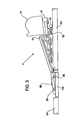
- Figure 2 shows the lift apparatus (5) in a partially retracted position.
- the lift apparatus (5) could be in the process of being extended to the floor for use or being retracted from the floor (200) (not shown in this view) to a fully retracted storage position above the ceiling (100).
- the lift platform (14) will ordinarily be fully retracted and in proximity to the lift motor (17).
- the control arm (53) is moving on the guide roller (19) in positioning guide slot (23) and is positioned approximately midway along the positioning acme drive (52) and is also approximately midway along the positioning guide slot (23) on the positioning guide (20).
- the trap door (110) is shown in a partially retracted position.
- the lift trolley (95) is shown on top of the trap door (110).
- the controlled rotational bearings (90) are also shown in this view. The controlled rotational bearings (90) secure the purpose of additionally providing guidance and control to the lift rail (10) during the deployment or retraction procedure.
- Figure 3 shows the lift apparatus (5) retracted on the positioning guide (20).
- the ceiling door (110) is closed.
- the lift platform (14) is on the lift rail (10) in proximity to the lift rail motor (17).
- the ceiling door (110) is shown closed.
- the lift rail (10) is positioned within the lift trolley guide (95).
- the control arm (53) has moved along the positioning acme drive (52).
- the positioning slot end of the control arm (53) is in the fully retracted position in the control guide (20), bringing the lift rail (10) to an approximate horizontal position.
- the positioning acme drive (52) will reverse direction of rotation moving the control arm (53) away from the positioning motor (50), first forcing the slot end of the control arm (53) up and along the guide slot (23) and thereby tilting the lift rail (10) and forcing open the trap door (110).
- the positioning acme drive (52) continues to rotate, the lift rail (10) will be guided down the positioning guide slot (23) to where it ultimately reaches the fully deployed position as shown in Figure 1 .
- the lift rail (10) In the fully deployed position, the lift rail (10) will be perpendicular to the floor (200) (not seen in this view) with its weight supported by the floor (200).
- both the lift rail motor (17) and the positioning motor (50) will be operated by a radio actuated remote. Consequently, a user would first actuate the positioning motor (50) to lower the lift rail (10) into position on the floor. The user would then actuate the lift rail motor (17) to raise and lower the lift platform (14) as required.
- a radio actuated remote could also have other functions. It could have a touch screen or a menu to allow one to record dates and times of use and also record what was stored and removed from the storage space accessed by the lift apparatus (5). The remote control could search using dates, times, or the name of stored items and display the results.
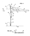
- Figure 4 shows an alternative embodiment of the current invention.
- This embodiment's construction is simplified to reduce the overall complexity and cost of the lift apparatus (5) but leaving unchanged the functional part of the lift apparatus (5) including the lift rail (10), the lift platform (14), the acme screw drive (15), and the lift motor (17).
- the lift rail motor (17) will use direct current, as will all the motors used in all embodiments of the lift apparatus (5).
- a direct current motor may use a battery back up so that the lift apparatus (5) will still be operable even when the alternating current supplied to the house through the power grid may be interrupted due to storms or for other reasons.
- the positioning guide (20), the accompanying positioning acme drive (52), and the positioning motor (50) are no longer used and are deleted from this embodiment.
- the lift motor (17) will be equipped with a clutch (not shown) which will provide not only a rotary motion for the acme drive (15) but also for a winch (60) which is connected by a cable (62) to an anchor (64).
- the lift rail (10) is connected to a rotary arm (70) which is mounted for rotary and sliding motion on a guide platform (75). (Shown in more detail in Figure 4A .) It is anticipated that the lift motor (17) and the accompanying clutch can be controlled by a remote radio actuated control.
- a user may use the remote control (not shown) to raise and lower the lift platform (14).
- the user would actuate the clutch in the lift motor (17) to begin to use the winch (60) to begin to coil the cable (62) on the winch (60) which would have the effect of tilting and pulling the lift rail (10) toward the anchor point (64).
- the rotary arm (70) along with the guide platform (75) makes sure the lift rail (10) stays in position.
- Controlled rotational bearings (90) are mounted on the ceiling door (110) in the lift control trolley (95) to serve two functions. First, they guide the lift rail (10) as it is being raised and lowered into position.
- the controlled rotational bearings (90) are designed to impede movement in one direction while freely allow any movement in another direction.
- the utility of the controlled rotational bearings (90) is to control the deployment of the lift rail (10) from the ceiling to the floor. For some reason if the cable (62) broke as the lift rail (10) was in the process of being deployed, the controlled rotational bearings (90) would stop the lift rail (10) from suddenly falling to the floor (200) possibly damaging the floor (200) or injuring a user.
- the controlled rotational bearings (90) are positioned so that they impede the motion of the lift rail (10) toward the floor (200) but allow the lift rail (10) to be readily raised from the floor (200) into the storage position in the ceiling (100).
- the embodiment shown in Figure 4 functions the same as the embodiment shown in Figures 1-3 but dispenses with the need for an extra positioning motor, positioning guide, and positioning acme drive.
- This embodiment still uses an electric motor to power the deployment from a storage position in the ceiling (100) to an in-use position resting on the floor (200) and back to a storage position, but this embodiment can be built with less expense since only one electric motor, the lift drive motor (17), is required.
- Figure 4A shows the guide platform (75) in more detail.
- the guide platform (75) is seen from the side.
- a rotary arm (70) is mounted within the guide platform slot (77) for slidable and rotatable movement.
- At one end of the guide platform (75) is a glide platform spring mounted bumper (79). This prevents the control arm (70) excessive rotation or movement while providing a fail-safe so that the lift rail (10) will not rotate beyond a perpendicular orientation to the floor (200) (not seen).
- this bumper (79) also helps control the deployment of the lift rail (10) to prevent uncontrolled movement of the lift rail (10) to the floor (200).
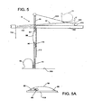
- FIG. 5 discloses another embodiment of the lift apparatus (5).
- the lift rail (10) uses an acme screw drive (15) powered by a lift rail motor (17).
- the lift rail (10) folds down from its storage position within the ceiling or attic area to extend and rest upon the floor (200).
- the deployment of the lift rail (10) from its storage position within the ceiling to its functional position resting on the floor (200) is accomplished manually, although with some mechanical assistance.
- the lift rail (10) is shown in dotted lines in the storage position and in solid lines in the extended position for use.
- the user would grasp the ceiling trap door (110) by the cord (112) and pull it downward to begin to open the trap door (110).
- Many expedients are available at this point to deploy the lift rail (10) from its storage position to its in-use position resting on the floor (200).
- a spring actuated cord (300) on a spring actuated coil (310).
- the spring actuated cord (300) extends as the lift rail (10) deploys but this extension is resisted by the spring coil (310).
- the spring coil (310) tends to prevent the lift rail (10) from precipitously falling under the force of gravity.
- the ceiling trap door (110) has the lift control trolley (95) with the controlled rotational bearings (90) to allow for a controlled deployment of the lift rail (10) from its storage position in the ceiling (100).
- the lift control trolley (95) also tends to more smoothly and accurately guide the lift rail (10) during deployment.
- the deployment of the lift rail (10) is accomplished by a user.
- the controlled rotational bearings (90), the lift trolley (95) and the spring actuated cord (300) and the spring actuated coil (310) all provide a fail safe mechanism to prevent unexpectedly fast or dangerous deployments of the lift rail (10) and also to provide a mechanical advantage to a user to require less strength from a user to alternately deploy the lift rail (10) to its resting position on the floor (200) or to its storage position in the ceiling (100).
- FIG 5A shows the lift trolley (95) in more detail.
- the lift rail (10) moves along the controlled rotational bearings (90).
- the controlled rotational bearings (90) allow the lift rail (10) to move freely from the deployed position to the storage position, but only allow a controlled deployment from the storage position to the deployed position.
- Shown in Figure 5A is a lift trolley spring mounted bumper (96) designed to resist downward movement of the lift rail (10).
- a bumper stop (not shown) can be affixed to the lift rail (10) at an appropriate position so that just as the lift rail (10) is approaching the fully perpendicular position to the floor (200), the trolley bumper (96) stops the lift rail (10) from “over deployment” to prevent the lift rail from crashing into the floor (200).
- the lift rail trolley (95), the controlled rotational bearings (90), and the lift trolley bumper (96) are all mechanisms to assure controlled appropriate deployment of the lift rail (10) from its storage position seen in the dotted lines in Figure 5 to its deployment position shown in the solid lines in Figure 5 .
- the lift rail trolley (95) and the accompanying mechanisms may be used in all embodiments, but would have their greatest application in the embodiment shown in Figure 5 where the deployment of the lift rail (10) is done mechanically by a user with little assistance from winches, acme drives and the like.
- the lift apparatus in this disclosure provides easier, safer, and more convenient means for obtaining access to a storage area in an attic or ceiling above a room.
- the lift apparatus can deploy automatically using direct current electric motors or can be deployed by a user using mechanical means. When the apparatus is deployed, the apparatus is not supported by ceiling joists but rather by the floor requiring no structural modification to the ceiling.
- the lift platform is raised and lowered using a fail-safe acme screw drive.
- the lift apparatus allows a person who may otherwise be unable to obtain convenient access to a storage area above a room to readily raise or lower larger or heavier loads than would be the case through a conventional fold down attic ladder.
- the lift apparatus enables a person who might not be able to use a ladder at all because of balance or medical problems to be able to simply ride the lift platform up to and from an attic area. Because of inaccessibility of an attic using a conventional fold down attic ladder, attics are rarely used to their full potential as storage areas.
- the lift apparatus fully remedies that shortcoming and allows users who would otherwise be unable to obtain access to a storage area in an attic to conveniently and easily use the lift apparatus to store items and to retrieve items from an attic.
Landscapes
- Engineering & Computer Science (AREA)
- Structural Engineering (AREA)
- Life Sciences & Earth Sciences (AREA)
- Geology (AREA)
- Mechanical Engineering (AREA)
- Automation & Control Theory (AREA)
- Types And Forms Of Lifts (AREA)
- Power-Operated Mechanisms For Wings (AREA)
Claims (18)
- Automatische Boden-zu-Decke- und Decke-zu-Boden-Hebevorrichtung (5), umfassend:(a) eine feste Schiene (10) mit einer vorgegebenen Länge;(b) ein Mittel zum Verbringen der festen Schiene (10) in eine und aus einer Unterbringungsstellung auf einer Decke (100) in eine senkrechte Arbeitsstellung, wobei ein erstes Bodenende der festen Schiene (10) von einem Boden (200) unter der Decke (100) getragen wird;(c) eine bewegliche Hubplattform (4), die an der festen Schiene (10) montiert und entlang der festen Schiene (10) beweglich ist, während sich die Schiene (10) in der senkrechten Arbeitsstellung befindet;(d) ein Mittel zum Bereitstellen von Energie für die Bewegung der Hubplattform (4) entlang von mindestens einem Abschnitt einer Längsabmessung der festen Schiene (10);wodurch die Hebevorrichtung (5) auf einer Decke (100) untergebracht werden kann, anschließend ausgefahren werden kann, um auf einem Boden (200) eines Raums unter der Decke (100) aufzuliegen und von ihm getragen zu werden, und die bewegliche Hubplattform (4) verwendet werden kann, um Gegenstände entlang einem Abschnitt der Längsabmessung der festen Schiene (10) zu bewegen, und dann erneut auf der Decke (100) untergebracht werden kann.
- Automatische Boden-zu-Decke- und Decke-zu-Boden-Hebevorrichtung (5) nach Anspruch 1, wobei die Decke (100) einen Dachgeschossboden eines Dachgeschossbereichs über dem Raum definiert und die feste Schiene (10) mit vorgegebener Länge an dem Dachgeschossboden über einem Raum montiert ist, wodurch die feste Schiene (10) in einer Unterbringungsstellung in dem Dachgeschossbereich auf dem Dachgeschossboden platziert ist und die feste Schiene (10) für einen Bewohner des Raums nicht zu sehen ist, wenn sie sich in der Unterbringungsstellung befindet.
- Automatische Boden-zu-Decke- und Decke-zu-Boden-Hebevorrichtung (5) nach Anspruch 2, wobei das Mittel zum Bereitstellen von Energie für die Bewegung der Hubplattform (4), zumindest teilweise, einen Hubelektromotor (17) umfasst, um einen Hubgewindetrieb (15) in der festen Schiene (10) anzutreiben, der Hubelektromotor (17) den Hubgewindetrieb (15) dreht, um die Hubplattform (4) entlang dem Hubgewindetrieb (15) in der festen Schiene (10) hochzufahren und herabzufahren.
- Automatische Boden-zu-Decke- und Decke-zu-Boden-Hebevorrichtung (5) nach Anspruch 3, wobei das Verbringungsmittel einen Verbringungselektromotor (17) umfasst, um einen Verbringungsgewindetrieb (15) anzutreiben, der Verbringungselektromotor (17) den Verbringungsgewindetrieb (15) dreht, um die feste Schiene (10) entlang einer Platzierungsführung (20) aus einer Unterbringungsstellung in dem Dachgeschoss in eine Arbeitsstellung zu bewegen, wo die Hubschiene (10) auf einem Boden (200) eines Raums unter der Decke (100) und dem Dachgeschoss aufliegt und von ihm getragen wird.
- Automatische Boden-zu-Decke- und Decke-zu-Boden-Hebevorrichtung (5) nach Anspruch 4, wobei der Hubelektromotor (17) ferner eine elektronische Hubsteuerung umfasst, sodass der Betrieb des Hubelektromotors (17) von der elektronischen Steuerung gesteuert wird.
- Automatische Boden-zu-Decke- und Decke-zu-Boden-Hebevorrichtung (5) nach Anspruch 5, wobei der Verbringungselektromotor (17) ferner eine elektronische Verbringungssteuerung umfasst, sodass der Betrieb des Verbringungselektromotors (17) von der elektronischen Steuerung gesteuert wird.
- Automatische Boden-zu-Decke- und Decke-zu-Boden-Hebevorrichtung (5) nach Anspruch 6, wobei die elektronische Hub- und Verbringungssteuerung ferner ein entferntes drahtloses Mittel zum Betätigen der elektronischen Hub- und Verbringungssteuerung umfasst.
- Automatische Boden-zu-Decke- und Decke-zu-Boden-Hebevorrichtung (5) nach Anspruch 7, wobei das entfernte drahtlose Mittel ferner einen elektronischen Speicher umfasst, wobei das entfernte drahtlose Mittel Daten aufzeichnen, suchen und anzeigen kann, sodass ein Verzeichnis von in dem Dachgeschoss aufbewahrten Gegenständen erstellt werden kann.
- Automatische Boden-zu-Decke- und Decke-zu-Boden-Hebevorrichtung (5) nach Anspruch 3, wobei das Verbringungsmittel eine Verbringungswinde umfasst, die von dem Hubelektromotor (17) angetrieben wird, wobei die Verbringungswinde ein Seil nutzt, das an einem Anker in dem Dachgeschossboden befestigt ist, wodurch die Winde das Seil einzieht, um die Hubschiene (10) in Richtung des Ankers auf dem Dachgeschossboden zu ziehen, um die Hebevorrichtung (5) in eine Unterbringungsstellung zu bewegen, und die Winde das Seil ausgibt, um die Hubschiene (10) in eine Arbeitsstellung zu bewegen, wo die Hubschiene (10) auf einem Boden (200) eines Raums unter der Decke (100) aufliegt und von ihm getragen wird.
- Automatische Boden-zu-Decke- und Decke-zu-Boden-Hebevorrichtung (5) nach Anspruch 9, ferner umfassend eine Bodenluke (110) in dem Dachgeschossboden, an der Bodenluke (110) ein Hebevorrichtungslaufwerk (95), wobei die Hubschiene (10) mit gesteuerten Drehlagern verschiebbar an dem Hebevorrichtungslaufwerk (95) montiert ist, um die Verbringung der Hubschiene (10) an dem Hebevorrichtungslaufwerk (95) in eine Arbeitsstellung auf einem Boden (200) in einem Raum unter der Decke (100) zu steuern.
- Automatische Boden-zu-Decke- und Decke-zu-Boden-Hebevorrichtung (5) nach Anspruch 10, wobei der Hubelektromotor (17) ferner eine elektronische Hubsteuerung umfasst, sodass der Hubelektromotor (17) und die Verbringungswinde von der elektronischen Steuerung gesteuert werden.
- Automatische Boden-zu-Decke- und Decke-zu-Boden-Hebevorrichtung (5) nach Anspruch 11, wobei die elektronische Steuerung ferner ein entferntes drahtloses Mittel zum Betätigen der elektronischen Steuerung umfasst.
- Automatische Boden-zu-Decke- und Decke-zu-Boden-Hebevorrichtung (5) nach Anspruch 12, wobei das entfernte drahtlose Mittel ferner einen elektronischen Speicher umfasst, wobei das entfernte drahtlose Mittel Daten aufzeichnen und anzeigen kann, sodass ein Verzeichnis von in dem Dachgeschoss aufbewahrten Gegenständen erstellt werden kann.
- Automatische Boden-zu-Decke- und Decke-zu-Boden-Hebevorrichtung (5) nach Anspruch 3, wobei das Verbringungsmittel eine Bodenluke (110) in dem Dachgeschossboden umfasst, an der Luke ein Hebevorrichtungslaufwerk (95), wobei die Hubschiene (10) mit gesteuerten Drehlagern verschiebbar an dem Hebevorrichtungslaufwerk (95) montiert ist, um die Verbringung der Hubschiene (10) an dem Vorrichtungslaufwerk (95) mit einer Arbeitsstellung auf einem Boden (200) in einem Raum unter der Decke (100) zu steuern.
- Automatische Boden-zu-Decke- und Decke-zu-Boden-Hebevorrichtung (5) nach Anspruch 14, ferner umfassend Mittel zum manuellen Öffnen der Bodenluke (110) in dem Dachgeschossboden, während die Hubschiene aus einer Unterbringungsstellung auf dem Hebevorrichtungslaufwerk (95) mit gesteuerten Drehlagern in die Arbeitsstellung auf dem Boden (200) in einem Raum unter der Decke (100) verbracht wird, wenn die Bodenluke (110) manuell geöffnet wird.
- Automatische Boden-zu-Decke- und Decke-zu-Boden-Hebevorrichtung (5) nach Anspruch 15, wobei der Hubelektromotor (17) ferner eine elektronische Hubsteuerung umfasst, sodass der Betrieb des Hubelektromotors (17) von der elektronischen Steuerung gesteuert wird.
- Automatische Boden-zu-Decke- und Decke-zu-Boden-Hebevorrichtung (5) nach Anspruch 16, wobei die elektronische Hubsteuerung ferner ein entferntes drahtloses Mittel zum Betätigen der elektronischen Hubsteuerung umfasst.
- Automatische Boden-zu-Decke- und Decke-zu-Boden-Hebevorrichtung (5) nach Anspruch 17, wobei das entfernte drahtlose Mittel ferner einen elektronischen Speicher umfasst, wobei das entfernte drahtlose Mittel Daten aufzeichnen und anzeigen kann, sodass ein Verzeichnis von in dem Dachgeschoss aufbewahrten Gegenständen erstellt werden kann.
Priority Applications (1)
| Application Number | Priority Date | Filing Date | Title |
|---|---|---|---|
| PL07755902T PL2013546T3 (pl) | 2006-04-21 | 2007-04-20 | Urządzenie podnośnikowe |
Applications Claiming Priority (3)
| Application Number | Priority Date | Filing Date | Title |
|---|---|---|---|
| US79398306P | 2006-04-21 | 2006-04-21 | |
| US11/788,557 US8020667B2 (en) | 2006-04-21 | 2007-04-19 | Lift apparatus |
| PCT/US2007/009822 WO2007124149A2 (en) | 2006-04-21 | 2007-04-20 | Lift apparatus |
Publications (3)
| Publication Number | Publication Date |
|---|---|
| EP2013546A2 EP2013546A2 (de) | 2009-01-14 |
| EP2013546A4 EP2013546A4 (de) | 2011-09-07 |
| EP2013546B1 true EP2013546B1 (de) | 2013-09-18 |
Family
ID=38620074
Family Applications (1)
| Application Number | Title | Priority Date | Filing Date |
|---|---|---|---|
| EP07755902.9A Not-in-force EP2013546B1 (de) | 2006-04-21 | 2007-04-20 | Hebevorrichtung |
Country Status (5)
| Country | Link |
|---|---|
| US (1) | US8020667B2 (de) |
| EP (1) | EP2013546B1 (de) |
| CA (1) | CA2649785C (de) |
| PL (1) | PL2013546T3 (de) |
| WO (1) | WO2007124149A2 (de) |
Families Citing this family (6)
| Publication number | Priority date | Publication date | Assignee | Title |
|---|---|---|---|---|
| EP2119662B1 (de) * | 2007-02-14 | 2017-03-15 | Gogou Co., Ltd. | Bewegungssteuerverfahren, bewegungsaktivierungsvorrichtung und verfahren zur aktivierung der bewegung eines beweglichen körpers |
| US9586794B2 (en) | 2013-05-03 | 2017-03-07 | Illinois Tool Works Inc. | Winch having adjustable initial mechanical advantage |
| US20150000569A1 (en) * | 2013-06-27 | 2015-01-01 | Joseph Casino | Concealable suspended surfaces |
| US10207905B2 (en) | 2015-02-05 | 2019-02-19 | Schlumberger Technology Corporation | Control system for winch and capstan |
| CN109640599B (zh) * | 2019-01-15 | 2023-09-15 | 怀化学院 | 一种基于plc的电气自动化控制装置 |
| CN113513190A (zh) * | 2021-08-09 | 2021-10-19 | 深圳时代建筑科技有限公司 | 一种空间可调的Loft公寓 |
Family Cites Families (32)
| Publication number | Priority date | Publication date | Assignee | Title |
|---|---|---|---|---|
| US1811709A (en) * | 1929-01-19 | 1931-06-23 | Bessler Disappearing Stairway | Disappearing stairway |
| US1986620A (en) * | 1934-06-21 | 1935-01-01 | Atlantic Elevator Company | Elevator |
| US2086002A (en) * | 1934-08-27 | 1937-07-06 | Oscar F Shepard | Elevator |
| US3363790A (en) * | 1965-09-29 | 1968-01-16 | Miller Mfg Company Inc | Vehicle mounted container handling equipment |
| US3392959A (en) * | 1967-02-17 | 1968-07-16 | Lewis Samuel | Bumper jack |
| US3478904A (en) * | 1967-05-17 | 1969-11-18 | Boeing Co | Cargo loading mechanism |
| US3606039A (en) * | 1969-05-12 | 1971-09-20 | Interstate Restaurant Supply C | Stacker crane system |
| DE2052192C3 (de) * | 1970-10-23 | 1975-02-27 | Messerschmitt-Boelkow-Blohm Gmbh, 8000 Muenchen | Bordeigenes Frachtbeladegerät für Flugzeuge |
| US3791541A (en) * | 1971-02-16 | 1974-02-12 | Leyman Mfg Corp | Cargo platform |
| GB1371744A (en) * | 1972-03-25 | 1974-10-23 | Messerschmitt Boelkow Blohm | On-board container-lifting appliance for aircraft |
| US3763964A (en) * | 1972-04-17 | 1973-10-09 | Equipment Syst Inc | Outside elevator |
| US3789955A (en) * | 1972-08-18 | 1974-02-05 | Raymond Lee Organization Inc | Retractable stairway device |
| US3951236A (en) * | 1974-12-20 | 1976-04-20 | Schreiber Raymond H | Mountable hoist |
| US3952974A (en) * | 1974-12-20 | 1976-04-27 | The Boeing Company | Cargo-handling system for standard body airplanes |
| US3985202A (en) * | 1975-06-23 | 1976-10-12 | Precision Parts Corporation | Hydraulically operated disappearing stairway |
| US4176732A (en) * | 1978-01-12 | 1979-12-04 | Nordskog Robert A | Self-propelled aircraft passenger elevator |
| FR2526774B1 (fr) * | 1982-05-11 | 1986-03-07 | Pichon Michel | Elevateur de chantier |
| US4586684A (en) * | 1983-09-01 | 1986-05-06 | Western Gear Corporation | Aircraft loading apparatus |
| US4579503A (en) * | 1983-11-02 | 1986-04-01 | Leyman Manufacturing Corp. | Sideloader elevator platform |
| SE461088B (sv) * | 1988-12-21 | 1990-01-08 | Alimak Ab | Anordning vid skruvhiss |
| US5076515A (en) * | 1989-03-08 | 1991-12-31 | Royal Flying Doctor Service Of Australia Inc. | Stretcher loading device for aircraft |
| US5122026A (en) * | 1990-09-17 | 1992-06-16 | Leyman Manufacturing Corp. | Cargo platform with plural storage positions |
| US5263808A (en) * | 1991-11-27 | 1993-11-23 | Leyman Manufacturing Corp. | Automatic storage latch system for a cargo platform |
| KR100196671B1 (ko) * | 1992-12-24 | 1999-06-15 | 이도 스스므 | 보수용 승강체 부착 입출장치 |
| US5535852A (en) * | 1994-08-17 | 1996-07-16 | Bishop; David J. | Lift apparatus |
| US5626208A (en) * | 1995-07-13 | 1997-05-06 | Sprague; Randy L. | Lift assembly |
| US5667035A (en) * | 1995-10-19 | 1997-09-16 | Hughes; Douglas J. | Overhead platform elevation device |
| US6131702A (en) * | 1998-05-29 | 2000-10-17 | Berridge; Harold Arthur | Home platform lift for attached garages |
| US6866118B1 (en) * | 2003-04-30 | 2005-03-15 | William D. Battenberg | Motorized access apparatus for elevated areas |
| US6962236B2 (en) * | 2003-09-08 | 2005-11-08 | Spacelift Products, Inc. | Platform lift apparatus with integrated ladder for accessing attic storage space |
| US7416055B2 (en) * | 2003-09-08 | 2008-08-26 | Spacelift Products, Inc. | Platform lift apparatus for attic storage space |
| US20060000675A1 (en) * | 2003-12-02 | 2006-01-05 | Penn Jay P | Platform lift apparatus for attic storage space |
-
2007
- 2007-04-19 US US11/788,557 patent/US8020667B2/en active Active - Reinstated
- 2007-04-20 WO PCT/US2007/009822 patent/WO2007124149A2/en not_active Ceased
- 2007-04-20 PL PL07755902T patent/PL2013546T3/pl unknown
- 2007-04-20 EP EP07755902.9A patent/EP2013546B1/de not_active Not-in-force
- 2007-04-20 CA CA2649785A patent/CA2649785C/en active Active
Also Published As
| Publication number | Publication date |
|---|---|
| US20070249280A1 (en) | 2007-10-25 |
| CA2649785A1 (en) | 2007-11-01 |
| CA2649785C (en) | 2014-10-28 |
| PL2013546T3 (pl) | 2014-02-28 |
| EP2013546A2 (de) | 2009-01-14 |
| WO2007124149A2 (en) | 2007-11-01 |
| US8020667B2 (en) | 2011-09-20 |
| EP2013546A4 (de) | 2011-09-07 |
| WO2007124149A3 (en) | 2008-12-24 |
Similar Documents
| Publication | Publication Date | Title |
|---|---|---|
| US6851376B2 (en) | Pull down shelf for overhead storage | |
| EP2013546B1 (de) | Hebevorrichtung | |
| US6866118B1 (en) | Motorized access apparatus for elevated areas | |
| US6223479B1 (en) | Extendable and retractable building and mechanism for extending and retracting | |
| US8028804B2 (en) | Automatic ladder for attic access | |
| US20170030071A1 (en) | Portable assembly convertable between a shipping unit and a building unit | |
| US7841448B2 (en) | Automatic ladder for attic access | |
| US8347560B2 (en) | Modular assembly | |
| US6886661B1 (en) | Motorized access ladder for elevated areas | |
| US20120005972A1 (en) | Folding loft stair assembly | |
| US5667035A (en) | Overhead platform elevation device | |
| US20100192487A1 (en) | Pivotal stairway systems and method | |
| US8302734B2 (en) | Hinged docking platform | |
| US9957720B1 (en) | Retractable staircase and method | |
| US20130213738A1 (en) | Compact Folding Step Stool | |
| KR20050075354A (ko) | 대피 시스템 및 방법 | |
| WO2022150562A1 (en) | Lift and storage system | |
| US20090166129A1 (en) | Power retractable stairway | |
| US3467460A (en) | Retractable clothes storage apparatus | |
| WO2007132272A1 (en) | Combination loft ladder & lift | |
| US20070269303A1 (en) | Combination loft ladder and lift | |
| US2506380A (en) | Foldaway stairway | |
| US20090071751A1 (en) | Portable aerial platform | |
| US11945701B1 (en) | Lift | |
| US20060277848A1 (en) | Telescoping stairway for accessing attic storage space |
Legal Events
| Date | Code | Title | Description |
|---|---|---|---|
| PUAI | Public reference made under article 153(3) epc to a published international application that has entered the european phase |
Free format text: ORIGINAL CODE: 0009012 |
|
| 17P | Request for examination filed |
Effective date: 20081118 |
|
| AK | Designated contracting states |
Kind code of ref document: A2 Designated state(s): AT BE BG CH CY CZ DE DK EE ES FI FR GB GR HU IE IS IT LI LT LU LV MC MT NL PL PT RO SE SI SK TR |
|
| AX | Request for extension of the european patent |
Extension state: AL BA HR MK RS |
|
| R17D | Deferred search report published (corrected) |
Effective date: 20081224 |
|
| RIC1 | Information provided on ipc code assigned before grant |
Ipc: E04G 1/18 20060101ALI20090121BHEP Ipc: B66B 11/08 20060101ALI20090121BHEP Ipc: B66B 11/00 20060101AFI20090121BHEP |
|
| A4 | Supplementary search report drawn up and despatched |
Effective date: 20110808 |
|
| RIC1 | Information provided on ipc code assigned before grant |
Ipc: B66B 11/08 20060101ALI20110802BHEP Ipc: E04G 1/18 20060101ALI20110802BHEP Ipc: B66B 9/00 20060101ALI20110802BHEP Ipc: B66B 11/00 20060101AFI20110802BHEP |
|
| DAX | Request for extension of the european patent (deleted) | ||
| REG | Reference to a national code |
Ref country code: DE Ref legal event code: R079 Ref document number: 602007032935 Country of ref document: DE Free format text: PREVIOUS MAIN CLASS: F24F0007007000 Ipc: B66B0011000000 |
|
| GRAP | Despatch of communication of intention to grant a patent |
Free format text: ORIGINAL CODE: EPIDOSNIGR1 |
|
| RIC1 | Information provided on ipc code assigned before grant |
Ipc: B66B 11/08 20060101ALI20130411BHEP Ipc: E04G 1/18 20060101ALI20130411BHEP Ipc: B66B 11/00 20060101AFI20130411BHEP Ipc: B66B 9/00 20060101ALI20130411BHEP |
|
| INTG | Intention to grant announced |
Effective date: 20130426 |
|
| GRAS | Grant fee paid |
Free format text: ORIGINAL CODE: EPIDOSNIGR3 |
|
| GRAA | (expected) grant |
Free format text: ORIGINAL CODE: 0009210 |
|
| AK | Designated contracting states |
Kind code of ref document: B1 Designated state(s): AT BE BG CH CY CZ DE DK EE ES FI FR GB GR HU IE IS IT LI LT LU LV MC MT NL PL PT RO SE SI SK TR |
|
| REG | Reference to a national code |
Ref country code: GB Ref legal event code: FG4D |
|
| REG | Reference to a national code |
Ref country code: CH Ref legal event code: EP |
|
| REG | Reference to a national code |
Ref country code: IE Ref legal event code: FG4D |
|
| REG | Reference to a national code |
Ref country code: AT Ref legal event code: REF Ref document number: 632645 Country of ref document: AT Kind code of ref document: T Effective date: 20131015 |
|
| REG | Reference to a national code |
Ref country code: DE Ref legal event code: R096 Ref document number: 602007032935 Country of ref document: DE Effective date: 20131114 |
|
| PG25 | Lapsed in a contracting state [announced via postgrant information from national office to epo] |
Ref country code: SE Free format text: LAPSE BECAUSE OF FAILURE TO SUBMIT A TRANSLATION OF THE DESCRIPTION OR TO PAY THE FEE WITHIN THE PRESCRIBED TIME-LIMIT Effective date: 20130918 Ref country code: CY Free format text: LAPSE BECAUSE OF FAILURE TO SUBMIT A TRANSLATION OF THE DESCRIPTION OR TO PAY THE FEE WITHIN THE PRESCRIBED TIME-LIMIT Effective date: 20130619 Ref country code: LT Free format text: LAPSE BECAUSE OF FAILURE TO SUBMIT A TRANSLATION OF THE DESCRIPTION OR TO PAY THE FEE WITHIN THE PRESCRIBED TIME-LIMIT Effective date: 20130918 |
|
| REG | Reference to a national code |
Ref country code: NL Ref legal event code: VDEP Effective date: 20130918 |
|
| REG | Reference to a national code |
Ref country code: AT Ref legal event code: MK05 Ref document number: 632645 Country of ref document: AT Kind code of ref document: T Effective date: 20130918 |
|
| REG | Reference to a national code |
Ref country code: LT Ref legal event code: MG4D |
|
| PG25 | Lapsed in a contracting state [announced via postgrant information from national office to epo] |
Ref country code: SI Free format text: LAPSE BECAUSE OF FAILURE TO SUBMIT A TRANSLATION OF THE DESCRIPTION OR TO PAY THE FEE WITHIN THE PRESCRIBED TIME-LIMIT Effective date: 20130918 Ref country code: FI Free format text: LAPSE BECAUSE OF FAILURE TO SUBMIT A TRANSLATION OF THE DESCRIPTION OR TO PAY THE FEE WITHIN THE PRESCRIBED TIME-LIMIT Effective date: 20130918 Ref country code: LV Free format text: LAPSE BECAUSE OF FAILURE TO SUBMIT A TRANSLATION OF THE DESCRIPTION OR TO PAY THE FEE WITHIN THE PRESCRIBED TIME-LIMIT Effective date: 20130918 Ref country code: GR Free format text: LAPSE BECAUSE OF FAILURE TO SUBMIT A TRANSLATION OF THE DESCRIPTION OR TO PAY THE FEE WITHIN THE PRESCRIBED TIME-LIMIT Effective date: 20131219 |
|
| REG | Reference to a national code |
Ref country code: PL Ref legal event code: T3 |
|
| PG25 | Lapsed in a contracting state [announced via postgrant information from national office to epo] |
Ref country code: BE Free format text: LAPSE BECAUSE OF FAILURE TO SUBMIT A TRANSLATION OF THE DESCRIPTION OR TO PAY THE FEE WITHIN THE PRESCRIBED TIME-LIMIT Effective date: 20130918 Ref country code: CY Free format text: LAPSE BECAUSE OF FAILURE TO SUBMIT A TRANSLATION OF THE DESCRIPTION OR TO PAY THE FEE WITHIN THE PRESCRIBED TIME-LIMIT Effective date: 20130918 |
|
| PG25 | Lapsed in a contracting state [announced via postgrant information from national office to epo] |
Ref country code: CZ Free format text: LAPSE BECAUSE OF FAILURE TO SUBMIT A TRANSLATION OF THE DESCRIPTION OR TO PAY THE FEE WITHIN THE PRESCRIBED TIME-LIMIT Effective date: 20130918 Ref country code: EE Free format text: LAPSE BECAUSE OF FAILURE TO SUBMIT A TRANSLATION OF THE DESCRIPTION OR TO PAY THE FEE WITHIN THE PRESCRIBED TIME-LIMIT Effective date: 20130918 Ref country code: SK Free format text: LAPSE BECAUSE OF FAILURE TO SUBMIT A TRANSLATION OF THE DESCRIPTION OR TO PAY THE FEE WITHIN THE PRESCRIBED TIME-LIMIT Effective date: 20130918 Ref country code: NL Free format text: LAPSE BECAUSE OF FAILURE TO SUBMIT A TRANSLATION OF THE DESCRIPTION OR TO PAY THE FEE WITHIN THE PRESCRIBED TIME-LIMIT Effective date: 20130918 Ref country code: IS Free format text: LAPSE BECAUSE OF FAILURE TO SUBMIT A TRANSLATION OF THE DESCRIPTION OR TO PAY THE FEE WITHIN THE PRESCRIBED TIME-LIMIT Effective date: 20140118 Ref country code: RO Free format text: LAPSE BECAUSE OF FAILURE TO SUBMIT A TRANSLATION OF THE DESCRIPTION OR TO PAY THE FEE WITHIN THE PRESCRIBED TIME-LIMIT Effective date: 20130918 |
|
| PG25 | Lapsed in a contracting state [announced via postgrant information from national office to epo] |
Ref country code: ES Free format text: LAPSE BECAUSE OF FAILURE TO SUBMIT A TRANSLATION OF THE DESCRIPTION OR TO PAY THE FEE WITHIN THE PRESCRIBED TIME-LIMIT Effective date: 20130918 Ref country code: AT Free format text: LAPSE BECAUSE OF FAILURE TO SUBMIT A TRANSLATION OF THE DESCRIPTION OR TO PAY THE FEE WITHIN THE PRESCRIBED TIME-LIMIT Effective date: 20130918 |
|
| REG | Reference to a national code |
Ref country code: DE Ref legal event code: R097 Ref document number: 602007032935 Country of ref document: DE |
|
| PG25 | Lapsed in a contracting state [announced via postgrant information from national office to epo] |
Ref country code: PT Free format text: LAPSE BECAUSE OF FAILURE TO SUBMIT A TRANSLATION OF THE DESCRIPTION OR TO PAY THE FEE WITHIN THE PRESCRIBED TIME-LIMIT Effective date: 20140120 |
|
| PLBE | No opposition filed within time limit |
Free format text: ORIGINAL CODE: 0009261 |
|
| STAA | Information on the status of an ep patent application or granted ep patent |
Free format text: STATUS: NO OPPOSITION FILED WITHIN TIME LIMIT |
|
| 26N | No opposition filed |
Effective date: 20140619 |
|
| PG25 | Lapsed in a contracting state [announced via postgrant information from national office to epo] |
Ref country code: IT Free format text: LAPSE BECAUSE OF FAILURE TO SUBMIT A TRANSLATION OF THE DESCRIPTION OR TO PAY THE FEE WITHIN THE PRESCRIBED TIME-LIMIT Effective date: 20130918 |
|
| PG25 | Lapsed in a contracting state [announced via postgrant information from national office to epo] |
Ref country code: DK Free format text: LAPSE BECAUSE OF FAILURE TO SUBMIT A TRANSLATION OF THE DESCRIPTION OR TO PAY THE FEE WITHIN THE PRESCRIBED TIME-LIMIT Effective date: 20130918 |
|
| REG | Reference to a national code |
Ref country code: DE Ref legal event code: R097 Ref document number: 602007032935 Country of ref document: DE Effective date: 20140619 |
|
| PG25 | Lapsed in a contracting state [announced via postgrant information from national office to epo] |
Ref country code: LU Free format text: LAPSE BECAUSE OF FAILURE TO SUBMIT A TRANSLATION OF THE DESCRIPTION OR TO PAY THE FEE WITHIN THE PRESCRIBED TIME-LIMIT Effective date: 20140420 Ref country code: MC Free format text: LAPSE BECAUSE OF FAILURE TO SUBMIT A TRANSLATION OF THE DESCRIPTION OR TO PAY THE FEE WITHIN THE PRESCRIBED TIME-LIMIT Effective date: 20130918 |
|
| REG | Reference to a national code |
Ref country code: CH Ref legal event code: PL |
|
| GBPC | Gb: european patent ceased through non-payment of renewal fee |
Effective date: 20140420 |
|
| REG | Reference to a national code |
Ref country code: GB Ref legal event code: S28 Free format text: APPLICATION FILED Ref country code: IE Ref legal event code: MM4A |
|
| PG25 | Lapsed in a contracting state [announced via postgrant information from national office to epo] |
Ref country code: GB Free format text: LAPSE BECAUSE OF NON-PAYMENT OF DUE FEES Effective date: 20140420 Ref country code: LI Free format text: LAPSE BECAUSE OF NON-PAYMENT OF DUE FEES Effective date: 20140430 Ref country code: CH Free format text: LAPSE BECAUSE OF NON-PAYMENT OF DUE FEES Effective date: 20140430 |
|
| REG | Reference to a national code |
Ref country code: GB Ref legal event code: S28 Free format text: RESTORATION ALLOWED Effective date: 20150205 |
|
| PG25 | Lapsed in a contracting state [announced via postgrant information from national office to epo] |
Ref country code: IE Free format text: LAPSE BECAUSE OF NON-PAYMENT OF DUE FEES Effective date: 20140420 |
|
| PG25 | Lapsed in a contracting state [announced via postgrant information from national office to epo] |
Ref country code: MT Free format text: LAPSE BECAUSE OF FAILURE TO SUBMIT A TRANSLATION OF THE DESCRIPTION OR TO PAY THE FEE WITHIN THE PRESCRIBED TIME-LIMIT Effective date: 20130918 |
|
| REG | Reference to a national code |
Ref country code: FR Ref legal event code: PLFP Year of fee payment: 10 |
|
| PG25 | Lapsed in a contracting state [announced via postgrant information from national office to epo] |
Ref country code: BG Free format text: LAPSE BECAUSE OF FAILURE TO SUBMIT A TRANSLATION OF THE DESCRIPTION OR TO PAY THE FEE WITHIN THE PRESCRIBED TIME-LIMIT Effective date: 20130918 |
|
| PG25 | Lapsed in a contracting state [announced via postgrant information from national office to epo] |
Ref country code: TR Free format text: LAPSE BECAUSE OF FAILURE TO SUBMIT A TRANSLATION OF THE DESCRIPTION OR TO PAY THE FEE WITHIN THE PRESCRIBED TIME-LIMIT Effective date: 20130918 Ref country code: HU Free format text: LAPSE BECAUSE OF FAILURE TO SUBMIT A TRANSLATION OF THE DESCRIPTION OR TO PAY THE FEE WITHIN THE PRESCRIBED TIME-LIMIT; INVALID AB INITIO Effective date: 20070420 |
|
| REG | Reference to a national code |
Ref country code: FR Ref legal event code: PLFP Year of fee payment: 11 |
|
| REG | Reference to a national code |
Ref country code: FR Ref legal event code: PLFP Year of fee payment: 12 |
|
| PGFP | Annual fee paid to national office [announced via postgrant information from national office to epo] |
Ref country code: FR Payment date: 20200427 Year of fee payment: 14 Ref country code: DE Payment date: 20200429 Year of fee payment: 14 |
|
| PGFP | Annual fee paid to national office [announced via postgrant information from national office to epo] |
Ref country code: PL Payment date: 20200416 Year of fee payment: 14 |
|
| REG | Reference to a national code |
Ref country code: DE Ref legal event code: R119 Ref document number: 602007032935 Country of ref document: DE |
|
| PG25 | Lapsed in a contracting state [announced via postgrant information from national office to epo] |
Ref country code: DE Free format text: LAPSE BECAUSE OF NON-PAYMENT OF DUE FEES Effective date: 20211103 Ref country code: FR Free format text: LAPSE BECAUSE OF NON-PAYMENT OF DUE FEES Effective date: 20210430 |
|
| PG25 | Lapsed in a contracting state [announced via postgrant information from national office to epo] |
Ref country code: PL Free format text: LAPSE BECAUSE OF NON-PAYMENT OF DUE FEES Effective date: 20210420 |
|
| PGFP | Annual fee paid to national office [announced via postgrant information from national office to epo] |
Ref country code: GB Payment date: 20240425 Year of fee payment: 18 |
|
| GBPC | Gb: european patent ceased through non-payment of renewal fee |
Effective date: 20250420 |
|
| PG25 | Lapsed in a contracting state [announced via postgrant information from national office to epo] |
Ref country code: GB Free format text: LAPSE BECAUSE OF NON-PAYMENT OF DUE FEES Effective date: 20250420 |