EP2013495B1 - A locking device to prevent loosening of two screw action connections - Google Patents
A locking device to prevent loosening of two screw action connections Download PDFInfo
- Publication number
- EP2013495B1 EP2013495B1 EP07705299.1A EP07705299A EP2013495B1 EP 2013495 B1 EP2013495 B1 EP 2013495B1 EP 07705299 A EP07705299 A EP 07705299A EP 2013495 B1 EP2013495 B1 EP 2013495B1
- Authority
- EP
- European Patent Office
- Prior art keywords
- interconnecting part
- coil
- coils
- locking device
- limbs
- Prior art date
- Legal status (The legal status is an assumption and is not a legal conclusion. Google has not performed a legal analysis and makes no representation as to the accuracy of the status listed.)
- Active
Links
- 239000002184 metal Substances 0.000 claims description 5
- 241000251468 Actinopterygii Species 0.000 description 1
- 229910000639 Spring steel Inorganic materials 0.000 description 1
- 230000007797 corrosion Effects 0.000 description 1
- 238000005260 corrosion Methods 0.000 description 1
- 238000002788 crimping Methods 0.000 description 1
- 229910001220 stainless steel Inorganic materials 0.000 description 1
- 239000010935 stainless steel Substances 0.000 description 1
Images
Classifications
-
- B—PERFORMING OPERATIONS; TRANSPORTING
- B60—VEHICLES IN GENERAL
- B60B—VEHICLE WHEELS; CASTORS; AXLES FOR WHEELS OR CASTORS; INCREASING WHEEL ADHESION
- B60B3/00—Disc wheels, i.e. wheels with load-supporting disc body
- B60B3/14—Attaching disc body to hub ; Wheel adapters
- B60B3/16—Attaching disc body to hub ; Wheel adapters by bolts or the like
-
- F—MECHANICAL ENGINEERING; LIGHTING; HEATING; WEAPONS; BLASTING
- F16—ENGINEERING ELEMENTS AND UNITS; GENERAL MEASURES FOR PRODUCING AND MAINTAINING EFFECTIVE FUNCTIONING OF MACHINES OR INSTALLATIONS; THERMAL INSULATION IN GENERAL
- F16B—DEVICES FOR FASTENING OR SECURING CONSTRUCTIONAL ELEMENTS OR MACHINE PARTS TOGETHER, e.g. NAILS, BOLTS, CIRCLIPS, CLAMPS, CLIPS OR WEDGES; JOINTS OR JOINTING
- F16B39/00—Locking of screws, bolts or nuts
- F16B39/02—Locking of screws, bolts or nuts in which the locking takes place after screwing down
- F16B39/10—Locking of screws, bolts or nuts in which the locking takes place after screwing down by a plate, spring, wire or ring immovable with regard to the bolt or object and mainly perpendicular to the axis of the bolt
- F16B39/101—Locking of screws, bolts or nuts in which the locking takes place after screwing down by a plate, spring, wire or ring immovable with regard to the bolt or object and mainly perpendicular to the axis of the bolt with a plate, spring, wire or ring holding two or more nuts or bolt heads which are mainly in the same plane
Definitions
- the present invention concerns a locking device in the form of a clip to prevent loosening of two spaced apart screw action connectors, such as adjacent vehicle wheel nuts or adjacent nuts on railway fish plates.
- a locking device in the form of a clip to prevent loosening of two spaced apart screw action connectors, such as adjacent vehicle wheel nuts or adjacent nuts on railway fish plates.
- two spaced apart screw action connectors such as adjacent vehicle wheel nuts or adjacent nuts on railway fish plates.
- such a device is also usable on spaced apart nuts or heads of bolts in any other location.
- a locking device in the form of a wire clip for this purpose. It comprised a metal wire configured to provide a diagonal interconnecting part extending tangentially between first and second coils which are sized to fit around the respective nuts.
- the wire was crimped in the respective coil sections so that these could fit in form locking manner around angular edges of the respective nuts.
- Opposite ends of the wire were turned at an angle to extend outwards from the general plane of each coil to provide finger grips. It is believed that both hands of a user would be required to fit (or remove) such a device.
- GB 2132301 also discloses a metal wire locking clip for the same purpose and of the same general configuration, in that a diagonal interconnecting part extends tangentially between first and second coils which are sized to fit around the respective screw action connectors.
- first and second end portions of the wire extend tangentially from the respective first and second coils to provide first and second finger grip limbs.
- these limbs extend across and beyond the diagonal interconnecting part. The first limb extends across the interconnecting part at a location adjacent the second coil, while the second limb extends across the interconnecting part at a location adjacent the first coil.
- An object of the present invention is to provide a metal wire locking clip which is easier to fit (or remove) than the prior art devices while maintaining adequate tension of the coils around the respective nuts in use.
- a locking device to prevent loosening of two spaced apart screw action connectors comprises a metal wire configured to provide a diagonal interconnecting part extending tangentially between first and second coils, which are sized to fit around the respective screw action connectors, and first and second end portions which extend tangentially from the respective first and second coils across and beyond the diagonal interconnecting part to provide first and second finger grip limbs, but this device is characterised in that the first limb extends across the interconnecting part adjacent the first coil and the second limb extends across the interconnecting part adjacent the second coil so that end regions of the limbs are spaced apart and at opposite sides of the interconnecting part and are capable of being pressed towards each other in a direction transverse to the interconnecting part by the fingers of one hand, in order to loosen the respective coils to enable their location over, or removal from, the respective screw action connectors.
- this practical embodiment of the invention comprises a locking clip made from spring steel wire of round cross-section, although square or any other cross-section would be possible. It is preferably of stainless steel to minimise corrosion.
- the clip has a diagonal interconnecting part 10 extending tangentially between a first coil 12 and a second coil 14.
- Each of these coils, 12, 14 are of almost three complete helical turns. As viewed in Figure 1 , they are each coiled in an anticlockwise direction extending from the diagonal part 10 and above the plane of the diagonal part 10. Respective end portions of the wire extend tangentially from the coils 12, 14 as limbs 22, 24. These limbs 22, 24 extend across and beyond the diagonal part 10 as viewed in Figure 1 .
- the limb 22 leading from the first coil 12 extends directly across the diagonal part 10 adjacent said first coil 12, while the limb 24 leading from the second coil 14 extends directly across the diagonal part 10 adjacent the second coil 14.
- finger grips 32, 34 which lie at a convenient spacing apart at opposite sides of the diagonal part 10 and in a generally parallel disposition.
- These finger grips 32, 34 can readily be pressed towards each other by the fingers of one hand thereby to open up slightly both of the respective coils 12, 14. In use, this squeezing together of the finger grips 32, 34 enables the device to be easily placed onto adjacent nuts or other screw connectors. Obviously the diameter and spacing of the coils 12, 14 is selected to correspond to the particular screw connectors on which the device is to be used.
- Figure 1 the device is shown placed onto adjacent standard wheel nuts 16, 18 which have been tightened in a clockwise direction. As the finger grips 32, 34 are released the coils 12, 14 close tightly around the respective nuts 16, 18. This prevents the nuts 16, 18 from loosening as any anticlockwise rotation of either nut 16, 18 is effectively countered by correspondingly tightening of the relevant coil 12 or 14 in that direction owing to its frictional engagement with the nut.
- the device can be applied to them the opposite way up, in the orientation shown in Figure 2 , where the limbs 22, 24 extend across the diagonal part 10 at a spacing below said part.
- the finger grips 32, 34 can be squeezed together in just the same way in this reverse orientation.
- the coil sections of the wire could be crimped. However, that is not essential and the device can operate satisfactorily without such crimping, as in the illustrated embodiment. Also, the number of turns in each coil may differ in other embodiments.
Landscapes
- Engineering & Computer Science (AREA)
- General Engineering & Computer Science (AREA)
- Mechanical Engineering (AREA)
- Clamps And Clips (AREA)
- Mutual Connection Of Rods And Tubes (AREA)
- Details Of Connecting Devices For Male And Female Coupling (AREA)
Description
- The present invention concerns a locking device in the form of a clip to prevent loosening of two spaced apart screw action connectors, such as adjacent vehicle wheel nuts or adjacent nuts on railway fish plates. However, such a device is also usable on spaced apart nuts or heads of bolts in any other location.
- As long ago as 1924
GB 225149 -
GB 2132301 - The fitting of the aforesaid locking clip to adjacent wheel nuts (and its removal) is difficult to accomplish, requires use of both hands and also considerable manual strength and dexterity on the part of the user.
- An object of the present invention is to provide a metal wire locking clip which is easier to fit (or remove) than the prior art devices while maintaining adequate tension of the coils around the respective nuts in use.
- According to the present invention a locking device to prevent loosening of two spaced apart screw action connectors comprises a metal wire configured to provide a diagonal interconnecting part extending tangentially between first and second coils, which are sized to fit around the respective screw action connectors, and first and second end portions which extend tangentially from the respective first and second coils across and beyond the diagonal interconnecting part to provide first and second finger grip limbs, but this device is characterised in that the first limb extends across the interconnecting part adjacent the first coil and the second limb extends across the interconnecting part adjacent the second coil so that end regions of the limbs are spaced apart and at opposite sides of the interconnecting part and are capable of being pressed towards each other in a direction transverse to the interconnecting part by the fingers of one hand, in order to loosen the respective coils to enable their location over, or removal from, the respective screw action connectors.
- The invention will now be described further, by way of example, with reference to the accompanying drawings, in which:
-
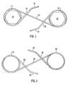
Figure 1 is a plan view of a practical embodiment of the locking device of the invention showing how it would fit over adjacent nuts; and -
Figure 2 is a similar view of the same device from the rear. - As illustrated, this practical embodiment of the invention comprises a locking clip made from spring steel wire of round cross-section, although square or any other cross-section would be possible. It is preferably of stainless steel to minimise corrosion.
- The clip has a diagonal interconnecting
part 10 extending tangentially between afirst coil 12 and asecond coil 14. Each of these coils, 12, 14 are of almost three complete helical turns. As viewed inFigure 1 , they are each coiled in an anticlockwise direction extending from thediagonal part 10 and above the plane of thediagonal part 10. Respective end portions of the wire extend tangentially from thecoils limbs limbs diagonal part 10 as viewed inFigure 1 . - The
limb 22 leading from thefirst coil 12 extends directly across thediagonal part 10 adjacent saidfirst coil 12, while thelimb 24 leading from thesecond coil 14 extends directly across thediagonal part 10 adjacent thesecond coil 14. - End regions of these
limbs finger grips diagonal part 10 and in a generally parallel disposition. Thesefinger grips respective coils finger grips coils - In
Figure 1 the device is shown placed onto adjacentstandard wheel nuts finger grips coils respective nuts nuts nut relevant coil - To cater for nuts which are tightened in an anticlockwise direction, the device can be applied to them the opposite way up, in the orientation shown in
Figure 2 , where thelimbs diagonal part 10 at a spacing below said part. Thefinger grips - The foregoing is not limitative and variations in detail are possible in other embodiments. For example, the coil sections of the wire could be crimped. However, that is not essential and the device can operate satisfactorily without such crimping, as in the illustrated embodiment. Also, the number of turns in each coil may differ in other embodiments.
Claims (4)
- A locking, device to prevent loosening of two spaced apart screw action connectors (16, 18), said device comprising a metal wire configured to provide a diagonal interconnecting part (10) extending tangentially between first and second coils (12, 14), which are sized to fit around the respective screw action connectors, and first and second end portions (22, 24) which extend tangentially from the respective first and second coils across and beyond the diagonal interconnecting part to provide first and second finger grip limbs, characterised in that the first limb (22) extends across the interconnecting part (10) adjacent the first coil (12) and the second limb (24) extends across the interconnecting part adjacent the second coil (14) so that end regions (32, 34) of the limbs are spaced apart and at opposite sides of the interconnecting part and are capable of being pressed towards each other in a direction transverse to the interconnecting part by the fingers of one hand in order to loosen the respective coils to enable their location over, or removal from, the respective screw action connectors.
- A locking device according to claim 1 wherein the end regions of the respective limbs (22, 24) are bent to define opposing finger grip regions (32, 34).
- A locking device according to claim 2 wherein the opposing bent finger grip regions (32, 34) extend substantially parallel to each other at opposite sides of the interconnecting part (10).
- A locking device according to any preceding claim wherein each coil (12, 14) comprises three turns of wire.
Priority Applications (3)
| Application Number | Priority Date | Filing Date | Title |
|---|---|---|---|
| SI200731373T SI2013495T1 (en) | 2006-04-25 | 2007-03-01 | A locking device to prevent loosening of two screw action connections |
| PL07705299T PL2013495T3 (en) | 2006-04-25 | 2007-03-01 | A locking device to prevent loosening of two screw action connections |
| CY20131101115T CY1115123T1 (en) | 2006-04-25 | 2013-12-11 | A LOCKING APPLIANCE TO PREVENT TWO ACTUATING CONNECTIONS |
Applications Claiming Priority (2)
| Application Number | Priority Date | Filing Date | Title |
|---|---|---|---|
| GB0608136A GB2437538B (en) | 2006-04-25 | 2006-04-25 | A locking device to prevent loosening of two screw action connectors |
| PCT/GB2007/000714 WO2007122367A1 (en) | 2006-04-25 | 2007-03-01 | A locking device to prevent loosening of two screw action connections |
Publications (2)
| Publication Number | Publication Date |
|---|---|
| EP2013495A1 EP2013495A1 (en) | 2009-01-14 |
| EP2013495B1 true EP2013495B1 (en) | 2013-09-11 |
Family
ID=36589752
Family Applications (1)
| Application Number | Title | Priority Date | Filing Date |
|---|---|---|---|
| EP07705299.1A Active EP2013495B1 (en) | 2006-04-25 | 2007-03-01 | A locking device to prevent loosening of two screw action connections |
Country Status (15)
| Country | Link |
|---|---|
| US (1) | US7891923B2 (en) |
| EP (1) | EP2013495B1 (en) |
| AU (1) | AU2007242641B2 (en) |
| BR (1) | BRPI0709640B1 (en) |
| CA (1) | CA2650031C (en) |
| CY (1) | CY1115123T1 (en) |
| DK (1) | DK2013495T3 (en) |
| ES (1) | ES2438978T3 (en) |
| GB (1) | GB2437538B (en) |
| MX (1) | MX2008013560A (en) |
| PL (1) | PL2013495T3 (en) |
| PT (1) | PT2013495E (en) |
| SI (1) | SI2013495T1 (en) |
| WO (1) | WO2007122367A1 (en) |
| ZA (1) | ZA200809592B (en) |
Families Citing this family (10)
| Publication number | Priority date | Publication date | Assignee | Title |
|---|---|---|---|---|
| CN101787999A (en) * | 2010-03-16 | 2010-07-28 | 重庆钢铁(集团)有限责任公司 | Method for preventing threaded connecting parts arranged in ring shape from loosening |
| US8529230B1 (en) * | 2010-10-26 | 2013-09-10 | Black Horse, Llc | Retaining mechanisms for threaded bodies in reciprocating pumps |
| US10661599B2 (en) * | 2013-05-07 | 2020-05-26 | Marchmont Pty Limited | Loose wheel nut indicator |
| GB2518409B (en) * | 2013-09-20 | 2015-07-29 | Nut Safety Ltd | Wheel nut locking device |
| USD733511S1 (en) * | 2013-12-31 | 2015-07-07 | Marchmont Pty Limited | Loose wheel nut indicator |
| GB2527073B (en) * | 2014-06-10 | 2017-05-17 | Parker Hannifin Mfg Ltd | A locking device for a threaded fastener |
| US9457882B1 (en) * | 2015-01-29 | 2016-10-04 | Brunswick Corporation | Mounting assembly and lock ring for marine stern drive engine |
| GB2597717A (en) * | 2020-07-30 | 2022-02-09 | Business Lines Ltd | A locking device to inhibit loosening of screw action fasteners |
| GB2597716A (en) * | 2020-07-30 | 2022-02-09 | Business Lines Ltd | A locking device to inhibit loosening of screw action fasteners |
| US20220056906A1 (en) * | 2020-08-21 | 2022-02-24 | LWF Services, LLC | Reciprocating Pump Packing Nut Assembly |
Family Cites Families (10)
| Publication number | Priority date | Publication date | Assignee | Title |
|---|---|---|---|---|
| US518641A (en) * | 1894-04-24 | Nut-lock | ||
| US581215A (en) * | 1897-04-20 | Joseph a | ||
| US642718A (en) * | 1899-11-03 | 1900-02-06 | Marcus Stine | Nut-lock. |
| US1172722A (en) * | 1914-06-05 | 1916-02-22 | William R Millard | Nut-lock. |
| US1544627A (en) * | 1924-06-30 | 1925-07-07 | Bateman Maurice John | Nut lock |
| GB225149A (en) * | 1924-06-30 | 1924-11-27 | Maurice John Bateman | Improvements in nut locks |
| NL20414C (en) * | 1926-09-08 | |||
| EP0114465B1 (en) * | 1982-11-24 | 1987-02-25 | Gerald Charles Rickwood | Screw-action connectors security means |
| GB2132301B (en) * | 1982-11-24 | 1987-04-15 | Gerald Charles Rickwood | Screw-action connectors security means |
| DE4121524C2 (en) * | 1991-06-28 | 1994-07-14 | Deutsche Aerospace Airbus | Screw connection |
-
2006
- 2006-04-25 GB GB0608136A patent/GB2437538B/en not_active Expired - Fee Related
-
2007
- 2007-03-01 AU AU2007242641A patent/AU2007242641B2/en not_active Ceased
- 2007-03-01 WO PCT/GB2007/000714 patent/WO2007122367A1/en active Application Filing
- 2007-03-01 ES ES07705299.1T patent/ES2438978T3/en active Active
- 2007-03-01 DK DK07705299.1T patent/DK2013495T3/en active
- 2007-03-01 SI SI200731373T patent/SI2013495T1/en unknown
- 2007-03-01 PL PL07705299T patent/PL2013495T3/en unknown
- 2007-03-01 MX MX2008013560A patent/MX2008013560A/en active IP Right Grant
- 2007-03-01 EP EP07705299.1A patent/EP2013495B1/en active Active
- 2007-03-01 US US12/226,674 patent/US7891923B2/en not_active Expired - Fee Related
- 2007-03-01 CA CA2650031A patent/CA2650031C/en active Active
- 2007-03-01 PT PT77052991T patent/PT2013495E/en unknown
- 2007-03-01 BR BRPI0709640A patent/BRPI0709640B1/en not_active IP Right Cessation
-
2008
- 2008-11-11 ZA ZA200809592A patent/ZA200809592B/en unknown
-
2013
- 2013-12-11 CY CY20131101115T patent/CY1115123T1/en unknown
Also Published As
| Publication number | Publication date |
|---|---|
| DK2013495T3 (en) | 2014-01-06 |
| GB2437538B (en) | 2009-11-25 |
| US7891923B2 (en) | 2011-02-22 |
| EP2013495A1 (en) | 2009-01-14 |
| US20090116928A1 (en) | 2009-05-07 |
| PL2013495T3 (en) | 2014-04-30 |
| AU2007242641B2 (en) | 2011-04-14 |
| CA2650031A1 (en) | 2007-11-01 |
| WO2007122367A1 (en) | 2007-11-01 |
| PT2013495E (en) | 2013-12-16 |
| GB0608136D0 (en) | 2006-06-07 |
| ES2438978T3 (en) | 2014-01-21 |
| BRPI0709640B1 (en) | 2018-11-06 |
| AU2007242641A1 (en) | 2007-11-01 |
| CY1115123T1 (en) | 2016-12-14 |
| GB2437538A (en) | 2007-10-31 |
| CA2650031C (en) | 2014-07-08 |
| ZA200809592B (en) | 2009-11-25 |
| MX2008013560A (en) | 2009-01-15 |
| SI2013495T1 (en) | 2014-04-30 |
| BRPI0709640A2 (en) | 2011-07-19 |
Similar Documents
| Publication | Publication Date | Title |
|---|---|---|
| EP2013495B1 (en) | A locking device to prevent loosening of two screw action connections | |
| US11130215B2 (en) | Methods and systems for increasing the efficiency of a remote wrench | |
| US5179044A (en) | Securing device for male plug/female socket connectors | |
| US3962936A (en) | Strap wrench | |
| US4646593A (en) | Looped strap wrench for rotating cylindrical objects | |
| US6095450A (en) | Pivot for a winding device | |
| WO2022023755A1 (en) | A locking device to inhibit loosening of screw action fasteners | |
| US20060053983A1 (en) | Oil filter canister tool | |
| US5323671A (en) | Ratchet tool | |
| WO2022023754A1 (en) | A locking device to inhibit loosening of screw action fasteners | |
| US20060278048A1 (en) | Flange wrench | |
| US8117948B2 (en) | Wrench | |
| US1328744A (en) | Pipe-wrench | |
| US20050156084A1 (en) | T-connector holding tool and method | |
| CA2942802A1 (en) | Faucet wrench | |
| GB2535647A (en) | Methods and systems for increasing the efficiency of a remote wrench | |
| JP3113567U (en) | Simple binding machine | |
| US20180079058A1 (en) | Faucet Wrench | |
| JPS6036990Y2 (en) | Wire clamp gripping part | |
| CN102651529B (en) | Oblique angle Crimping Pliers | |
| JPS6137887Y2 (en) | ||
| JPH0662466U (en) | Terminal mounting structure | |
| JPH0738789U (en) | Fastening tool for fastening string | |
| JP2009225566A (en) | Cable fixture | |
| CZ21976U1 (en) | Torque wrench adapter |
Legal Events
| Date | Code | Title | Description |
|---|---|---|---|
| PUAI | Public reference made under article 153(3) epc to a published international application that has entered the european phase |
Free format text: ORIGINAL CODE: 0009012 |
|
| 17P | Request for examination filed |
Effective date: 20081111 |
|
| AK | Designated contracting states |
Kind code of ref document: A1 Designated state(s): AT BE BG CH CY CZ DE DK EE ES FI FR GB GR HU IE IS IT LI LT LU LV MC MT NL PL PT RO SE SI SK TR |
|
| AX | Request for extension of the european patent |
Extension state: AL BA HR MK RS |
|
| RAP1 | Party data changed (applicant data changed or rights of an application transferred) |
Owner name: BUSINESS LINES LIMITED |
|
| DAX | Request for extension of the european patent (deleted) | ||
| 17Q | First examination report despatched |
Effective date: 20121102 |
|
| GRAP | Despatch of communication of intention to grant a patent |
Free format text: ORIGINAL CODE: EPIDOSNIGR1 |
|
| INTG | Intention to grant announced |
Effective date: 20130408 |
|
| GRAS | Grant fee paid |
Free format text: ORIGINAL CODE: EPIDOSNIGR3 |
|
| GRAA | (expected) grant |
Free format text: ORIGINAL CODE: 0009210 |
|
| RBV | Designated contracting states (corrected) |
Designated state(s): AT BE BG CH CY CZ DE DK EE ES FI FR GR HU IE IS IT LI LT LU LV MC MT NL PL PT RO SE SI SK TR |
|
| AK | Designated contracting states |
Kind code of ref document: B1 Designated state(s): AT BE BG CH CY CZ DE DK EE ES FI FR GR HU IE IS IT LI LT LU LV MC MT NL PL PT RO SE SI SK TR |
|
| REG | Reference to a national code |
Ref country code: CH Ref legal event code: EP |
|
| REG | Reference to a national code |
Ref country code: AT Ref legal event code: REF Ref document number: 631804 Country of ref document: AT Kind code of ref document: T Effective date: 20130915 |
|
| REG | Reference to a national code |
Ref country code: IE Ref legal event code: FG4D |
|
| REG | Reference to a national code |
Ref country code: DE Ref legal event code: R096 Ref document number: 602007032784 Country of ref document: DE Effective date: 20131107 |
|
| REG | Reference to a national code |
Ref country code: RO Ref legal event code: EPE |
|
| REG | Reference to a national code |
Ref country code: PT Ref legal event code: SC4A Free format text: AVAILABILITY OF NATIONAL TRANSLATION Effective date: 20131209 |
|
| REG | Reference to a national code |
Ref country code: NL Ref legal event code: T3 |
|
| REG | Reference to a national code |
Ref country code: DK Ref legal event code: T3 Effective date: 20131216 |
|
| REG | Reference to a national code |
Ref country code: SE Ref legal event code: TRGR Ref country code: ES Ref legal event code: FG2A Ref document number: 2438978 Country of ref document: ES Kind code of ref document: T3 Effective date: 20140121 |
|
| REG | Reference to a national code |
Ref country code: CH Ref legal event code: NV Representative=s name: MEYER AND KOLLEGEN, CH |
|
| REG | Reference to a national code |
Ref country code: GR Ref legal event code: EP Ref document number: 20130402644 Country of ref document: GR Effective date: 20140124 |
|
| REG | Reference to a national code |
Ref country code: EE Ref legal event code: FG4A Ref document number: E008993 Country of ref document: EE Effective date: 20131210 |
|
| REG | Reference to a national code |
Ref country code: PL Ref legal event code: T3 |
|
| REG | Reference to a national code |
Ref country code: SK Ref legal event code: T3 Ref document number: E 15596 Country of ref document: SK |
|
| REG | Reference to a national code |
Ref country code: DE Ref legal event code: R097 Ref document number: 602007032784 Country of ref document: DE |
|
| PLBE | No opposition filed within time limit |
Free format text: ORIGINAL CODE: 0009261 |
|
| STAA | Information on the status of an ep patent application or granted ep patent |
Free format text: STATUS: NO OPPOSITION FILED WITHIN TIME LIMIT |
|
| REG | Reference to a national code |
Ref country code: HU Ref legal event code: AG4A Ref document number: E019660 Country of ref document: HU |
|
| 26N | No opposition filed |
Effective date: 20140612 |
|
| REG | Reference to a national code |
Ref country code: DE Ref legal event code: R097 Ref document number: 602007032784 Country of ref document: DE Effective date: 20140612 |
|
| REG | Reference to a national code |
Ref country code: FR Ref legal event code: PLFP Year of fee payment: 9 |
|
| REG | Reference to a national code |
Ref country code: FR Ref legal event code: PLFP Year of fee payment: 10 |
|
| REG | Reference to a national code |
Ref country code: FR Ref legal event code: PLFP Year of fee payment: 11 |
|
| REG | Reference to a national code |
Ref country code: FR Ref legal event code: PLFP Year of fee payment: 12 |
|
| PGFP | Annual fee paid to national office [announced via postgrant information from national office to epo] |
Ref country code: LT Payment date: 20220203 Year of fee payment: 16 Ref country code: IE Payment date: 20220311 Year of fee payment: 16 Ref country code: HU Payment date: 20220208 Year of fee payment: 16 Ref country code: FI Payment date: 20220304 Year of fee payment: 16 Ref country code: DK Payment date: 20220308 Year of fee payment: 16 Ref country code: DE Payment date: 20220311 Year of fee payment: 16 Ref country code: BG Payment date: 20220307 Year of fee payment: 16 Ref country code: AT Payment date: 20220307 Year of fee payment: 16 |
|
| PGFP | Annual fee paid to national office [announced via postgrant information from national office to epo] |
Ref country code: IS Payment date: 20220302 Year of fee payment: 16 Ref country code: TR Payment date: 20220203 Year of fee payment: 16 Ref country code: SK Payment date: 20220203 Year of fee payment: 16 Ref country code: SE Payment date: 20220318 Year of fee payment: 16 Ref country code: RO Payment date: 20220207 Year of fee payment: 16 Ref country code: PT Payment date: 20220203 Year of fee payment: 16 Ref country code: PL Payment date: 20220202 Year of fee payment: 16 Ref country code: NL Payment date: 20220315 Year of fee payment: 16 Ref country code: MT Payment date: 20220304 Year of fee payment: 16 Ref country code: MC Payment date: 20220309 Year of fee payment: 16 Ref country code: LV Payment date: 20220304 Year of fee payment: 16 Ref country code: LU Payment date: 20220304 Year of fee payment: 16 Ref country code: IT Payment date: 20220303 Year of fee payment: 16 Ref country code: GR Payment date: 20220304 Year of fee payment: 16 Ref country code: FR Payment date: 20220309 Year of fee payment: 16 Ref country code: EE Payment date: 20220304 Year of fee payment: 16 Ref country code: CZ Payment date: 20220202 Year of fee payment: 16 Ref country code: BE Payment date: 20220304 Year of fee payment: 16 |
|
| PGFP | Annual fee paid to national office [announced via postgrant information from national office to epo] |
Ref country code: SI Payment date: 20220203 Year of fee payment: 16 |
|
| PGFP | Annual fee paid to national office [announced via postgrant information from national office to epo] |
Ref country code: ES Payment date: 20220406 Year of fee payment: 16 Ref country code: CY Payment date: 20220209 Year of fee payment: 16 |
|
| PGFP | Annual fee paid to national office [announced via postgrant information from national office to epo] |
Ref country code: CH Payment date: 20220401 Year of fee payment: 16 |
|
| REG | Reference to a national code |
Ref country code: LT Ref legal event code: MM4D Effective date: 20230301 |
|
| REG | Reference to a national code |
Ref country code: DE Ref legal event code: R119 Ref document number: 602007032784 Country of ref document: DE |
|
| REG | Reference to a national code |
Ref country code: EE Ref legal event code: MM4A Ref document number: E008993 Country of ref document: EE Effective date: 20230331 |
|
| REG | Reference to a national code |
Ref country code: SK Ref legal event code: MM4A Ref document number: E 15596 Country of ref document: SK Effective date: 20230301 |
|
| PG25 | Lapsed in a contracting state [announced via postgrant information from national office to epo] |
Ref country code: RO Free format text: LAPSE BECAUSE OF NON-PAYMENT OF DUE FEES Effective date: 20230301 Ref country code: PT Free format text: LAPSE BECAUSE OF NON-PAYMENT OF DUE FEES Effective date: 20230901 Ref country code: MC Free format text: LAPSE BECAUSE OF NON-PAYMENT OF DUE FEES Effective date: 20230331 Ref country code: FI Free format text: LAPSE BECAUSE OF NON-PAYMENT OF DUE FEES Effective date: 20230301 Ref country code: CZ Free format text: LAPSE BECAUSE OF NON-PAYMENT OF DUE FEES Effective date: 20230301 Ref country code: CY Free format text: LAPSE BECAUSE OF NON-PAYMENT OF DUE FEES Effective date: 20230301 |
|
| REG | Reference to a national code |
Ref country code: SE Ref legal event code: EUG Ref country code: CH Ref legal event code: PL |
|
| REG | Reference to a national code |
Ref country code: DK Ref legal event code: EBP Effective date: 20230331 |
|
| REG | Reference to a national code |
Ref country code: NL Ref legal event code: MM Effective date: 20230401 |
|
| REG | Reference to a national code |
Ref country code: AT Ref legal event code: MM01 Ref document number: 631804 Country of ref document: AT Kind code of ref document: T Effective date: 20230301 |
|
| PG25 | Lapsed in a contracting state [announced via postgrant information from national office to epo] |
Ref country code: SK Free format text: LAPSE BECAUSE OF NON-PAYMENT OF DUE FEES Effective date: 20230301 Ref country code: SI Free format text: LAPSE BECAUSE OF NON-PAYMENT OF DUE FEES Effective date: 20230302 Ref country code: LV Free format text: LAPSE BECAUSE OF NON-PAYMENT OF DUE FEES Effective date: 20230301 Ref country code: LT Free format text: LAPSE BECAUSE OF NON-PAYMENT OF DUE FEES Effective date: 20230301 |
|
| REG | Reference to a national code |
Ref country code: BE Ref legal event code: MM Effective date: 20230331 Ref country code: SI Ref legal event code: KO00 Effective date: 20231020 |
|
| PG25 | Lapsed in a contracting state [announced via postgrant information from national office to epo] |
Ref country code: NL Free format text: LAPSE BECAUSE OF NON-PAYMENT OF DUE FEES Effective date: 20230401 Ref country code: LU Free format text: LAPSE BECAUSE OF NON-PAYMENT OF DUE FEES Effective date: 20230301 |
|
| REG | Reference to a national code |
Ref country code: IE Ref legal event code: MM4A |
|
| PG25 | Lapsed in a contracting state [announced via postgrant information from national office to epo] |
Ref country code: GR Free format text: LAPSE BECAUSE OF NON-PAYMENT OF DUE FEES Effective date: 20231009 |
|
| PG25 | Lapsed in a contracting state [announced via postgrant information from national office to epo] |
Ref country code: SE Free format text: LAPSE BECAUSE OF NON-PAYMENT OF DUE FEES Effective date: 20230302 Ref country code: LI Free format text: LAPSE BECAUSE OF NON-PAYMENT OF DUE FEES Effective date: 20230331 Ref country code: IE Free format text: LAPSE BECAUSE OF NON-PAYMENT OF DUE FEES Effective date: 20230301 Ref country code: HU Free format text: LAPSE BECAUSE OF NON-PAYMENT OF DUE FEES Effective date: 20230302 Ref country code: GR Free format text: LAPSE BECAUSE OF NON-PAYMENT OF DUE FEES Effective date: 20231009 Ref country code: FR Free format text: LAPSE BECAUSE OF NON-PAYMENT OF DUE FEES Effective date: 20230331 Ref country code: EE Free format text: LAPSE BECAUSE OF NON-PAYMENT OF DUE FEES Effective date: 20230331 Ref country code: DE Free format text: LAPSE BECAUSE OF NON-PAYMENT OF DUE FEES Effective date: 20231003 Ref country code: CH Free format text: LAPSE BECAUSE OF NON-PAYMENT OF DUE FEES Effective date: 20230331 Ref country code: AT Free format text: LAPSE BECAUSE OF NON-PAYMENT OF DUE FEES Effective date: 20230301 |
|
| PG25 | Lapsed in a contracting state [announced via postgrant information from national office to epo] |
Ref country code: BE Free format text: LAPSE BECAUSE OF NON-PAYMENT OF DUE FEES Effective date: 20230331 |
|
| PG25 | Lapsed in a contracting state [announced via postgrant information from national office to epo] |
Ref country code: ES Free format text: LAPSE BECAUSE OF NON-PAYMENT OF DUE FEES Effective date: 20230302 |
|
| REG | Reference to a national code |
Ref country code: ES Ref legal event code: FD2A Effective date: 20240426 |
|
| PG25 | Lapsed in a contracting state [announced via postgrant information from national office to epo] |
Ref country code: IT Free format text: LAPSE BECAUSE OF NON-PAYMENT OF DUE FEES Effective date: 20230301 Ref country code: ES Free format text: LAPSE BECAUSE OF NON-PAYMENT OF DUE FEES Effective date: 20230302 Ref country code: DK Free format text: LAPSE BECAUSE OF NON-PAYMENT OF DUE FEES Effective date: 20230331 |
|
| PG25 | Lapsed in a contracting state [announced via postgrant information from national office to epo] |
Ref country code: PL Free format text: LAPSE BECAUSE OF NON-PAYMENT OF DUE FEES Effective date: 20230301 |
|
| PG25 | Lapsed in a contracting state [announced via postgrant information from national office to epo] |
Ref country code: PL Free format text: LAPSE BECAUSE OF NON-PAYMENT OF DUE FEES Effective date: 20230301 |