EP2012414B1 - Low-noise, high-speed, high precision and high-thrust flux reversal motor for linear or rotary motion system - Google Patents
Low-noise, high-speed, high precision and high-thrust flux reversal motor for linear or rotary motion system Download PDFInfo
- Publication number
- EP2012414B1 EP2012414B1 EP08011496.0A EP08011496A EP2012414B1 EP 2012414 B1 EP2012414 B1 EP 2012414B1 EP 08011496 A EP08011496 A EP 08011496A EP 2012414 B1 EP2012414 B1 EP 2012414B1
- Authority
- EP
- European Patent Office
- Prior art keywords
- mover
- permanent magnets
- stator
- teeth
- flux reversal
- Prior art date
- Legal status (The legal status is an assumption and is not a legal conclusion. Google has not performed a legal analysis and makes no representation as to the accuracy of the status listed.)
- Active
Links
Images







Classifications
-
- H—ELECTRICITY
- H02—GENERATION; CONVERSION OR DISTRIBUTION OF ELECTRIC POWER
- H02K—DYNAMO-ELECTRIC MACHINES
- H02K41/00—Propulsion systems in which a rigid body is moved along a path due to dynamo-electric interaction between the body and a magnetic field travelling along the path
- H02K41/02—Linear motors; Sectional motors
- H02K41/03—Synchronous motors; Motors moving step by step; Reluctance motors
- H02K41/031—Synchronous motors; Motors moving step by step; Reluctance motors of the permanent magnet type
- H02K41/033—Synchronous motors; Motors moving step by step; Reluctance motors of the permanent magnet type with armature and magnets on one member, the other member being a flux distributor
-
- H—ELECTRICITY
- H02—GENERATION; CONVERSION OR DISTRIBUTION OF ELECTRIC POWER
- H02K—DYNAMO-ELECTRIC MACHINES
- H02K1/00—Details of the magnetic circuit
- H02K1/06—Details of the magnetic circuit characterised by the shape, form or construction
- H02K1/12—Stationary parts of the magnetic circuit
- H02K1/14—Stator cores with salient poles
- H02K1/146—Stator cores with salient poles consisting of a generally annular yoke with salient poles
- H02K1/148—Sectional cores
-
- H—ELECTRICITY
- H02—GENERATION; CONVERSION OR DISTRIBUTION OF ELECTRIC POWER
- H02K—DYNAMO-ELECTRIC MACHINES
- H02K1/00—Details of the magnetic circuit
- H02K1/06—Details of the magnetic circuit characterised by the shape, form or construction
- H02K1/22—Rotating parts of the magnetic circuit
- H02K1/24—Rotor cores with salient poles ; Variable reluctance rotors
- H02K1/246—Variable reluctance rotors
-
- H—ELECTRICITY
- H02—GENERATION; CONVERSION OR DISTRIBUTION OF ELECTRIC POWER
- H02K—DYNAMO-ELECTRIC MACHINES
- H02K21/00—Synchronous motors having permanent magnets; Synchronous generators having permanent magnets
- H02K21/12—Synchronous motors having permanent magnets; Synchronous generators having permanent magnets with stationary armatures and rotating magnets
- H02K21/14—Synchronous motors having permanent magnets; Synchronous generators having permanent magnets with stationary armatures and rotating magnets with magnets rotating within the armatures
- H02K21/20—Synchronous motors having permanent magnets; Synchronous generators having permanent magnets with stationary armatures and rotating magnets with magnets rotating within the armatures having windings each turn of which co-operates only with poles of one polarity, e.g. homopolar machine
-
- H—ELECTRICITY
- H02—GENERATION; CONVERSION OR DISTRIBUTION OF ELECTRIC POWER
- H02K—DYNAMO-ELECTRIC MACHINES
- H02K21/00—Synchronous motors having permanent magnets; Synchronous generators having permanent magnets
- H02K21/12—Synchronous motors having permanent magnets; Synchronous generators having permanent magnets with stationary armatures and rotating magnets
- H02K21/22—Synchronous motors having permanent magnets; Synchronous generators having permanent magnets with stationary armatures and rotating magnets with magnets rotating around the armatures, e.g. flywheel magnetos
-
- H—ELECTRICITY
- H02—GENERATION; CONVERSION OR DISTRIBUTION OF ELECTRIC POWER
- H02K—DYNAMO-ELECTRIC MACHINES
- H02K21/00—Synchronous motors having permanent magnets; Synchronous generators having permanent magnets
- H02K21/38—Synchronous motors having permanent magnets; Synchronous generators having permanent magnets with rotating flux distributors, and armatures and magnets both stationary
- H02K21/44—Synchronous motors having permanent magnets; Synchronous generators having permanent magnets with rotating flux distributors, and armatures and magnets both stationary with armature windings wound upon the magnets
-
- H—ELECTRICITY
- H02—GENERATION; CONVERSION OR DISTRIBUTION OF ELECTRIC POWER
- H02K—DYNAMO-ELECTRIC MACHINES
- H02K2213/00—Specific aspects, not otherwise provided for and not covered by codes H02K2201/00 - H02K2211/00
- H02K2213/03—Machines characterised by numerical values, ranges, mathematical expressions or similar information
Definitions
- the present invention relates generally to a flux reversal motor and, more particularly, to a linear motor, which can decrease the number of permanent magnets that are used, can facilitate magnetization using permanent magnets having the same polarities, can move at high speed because thrust is increased, and can realize low noise/low vibration and high precision position control by decreasing the pulsation of thrust and normal force, and to a rotary motor, which is based on the concept of the linear motor, and which can prevent the degradation of the permanent magnets from occurring because the permanent magnets are provided in a rotor, can prevent scattering from occurring because the permanent magnets are provided in a stator, and can be effectively manufactured by applying divided iron cores to a stator or rotor.
- a conventional permanent magnet linear synchronous motor is formed to have an actuation coil structure, in which permanent magnets are located in a stator, so that it has disadvantages in that the manufacturing cost thereof is inevitably increased because the movement distance is increased and, thus, the number of permanent magnets that are used is increased, and in that the pulsation of thrust and normal force are caused due to the end-effect, which occurs at the ends of the entry and exit of a mover.
- some applications of the conventional permanent magnet linear synchronous motor may be limited by the influence of the leakage magnetic flux, which is generated by the permanent magnets attached to the stator, on the surroundings.
- United States Patent No. 4,713,570 in its embodiment of Fig. 8 , discloses a flux reversal motor comprising a mover moving linearly relative to a stator and a plurality of permanent magnets. Further is disclosed a flux reversal motor comprising a moving body and a mover core.
- the present invention has been made keeping in mind the above problems occurring in the prior art, and the present invention is directed to provide a flux reversal linear motor, which can reduce the manufacturing cost thereof because the number of permanent magnets that are used is decreased, which can facilitate magnetization by enabling movable permanent magnets, having the same polarities, to be provided in a mover, which can decrease the pulsation of thrust and normal force by preventing an end-effect, such as the generation of leakage magnetic flux, from occurring through the appropriate arrangement of the movable permanent magnets, and which can also decrease detent force by applying a predetermined skew structure to a mover or stator core, thus realizing low noise/low vibration, high speeds, high precision, and high thrust motion.
- the present invention is directed to provide a flux reversal rotary motor, which is based on the concept of the linear motor, and which can decrease the number of permanent magnets that are used, can facilitate magnetization, can increase the torque, can decrease the pulsation of the torque, can prevent the degradation of permanent magnets, attributable to the heat that is generated by stator coils, from occurring because the permanent magnets are provided in the rotor, and can be economically and easily manufactured by applying divided iron cores to the stator or rotor.
- the present invention provides a flux reversal motor according to claim 1.
- the permanent magnets may be configured to have any of the triangular, rectangular, square, trapezoidal, pentagonal, and circular shapes, wherein at least one edge of each of the permanent magnets may be formed to have a round shape.
- the end of the protrusion may be configured to have any of rectilinear, round, angled, and chamfered shapes.
- the ends of teeth of the stator may be configured to have any of rectilinear, round, angled, and chamfered shapes.
- the permanent magnets may be configured in such a way that, when other elements of the mover are completed, predetermined magnets are attached to predetermined locations and are then magnetized.
- the iron cores of the stator or of the mover may be laminated such that the stator teeth and the mover teeth are opposite each other so as to have a predetermined skew structure.
- the stator may have a curved track for the motion of the mover.
- the mover may include mover teeth, the number of which is a multiple of three, which are arranged at an identical pitch in a motion direction.
- the ends of the mover teeth may have a length three or any odd number of times as great as the pole pitch of each of the permanent magnets in the motion direction.
- FIG. 1 is a view illustrating the mover and stator of a linear motor according to an embodiment of the present invention.
- the mover of the linear motor according to the embodiment of the present invention includes a mover core 1, mover teeth 2, permanent magnets 3, and mover phase coils 4.
- the stator of the linear motor according to the embodiment of the present invention includes a stator core 5 and stator teeth 6.
- the mover phase coils 4 which are formed by winding the coil around the mover teeth 2, as shown in FIG. 1 (X: inward direction, ⁇ : outward direction), the flow of magnetic flux that is generated by the permanent magnets 3 varies according to variation in the relative locations between the mover and the stator, and thus the thrust is generated. Accordingly, the mover, which is a linearly moving body, moves linearly relative to the stator.
- the permanent magnets 3, having the same polarities, are provided in the end of each mover tooth 2, as shown in FIG. 1 .
- the permanent magnets 3 are arranged on the left and right sides of the central protrusion A of the end of the mover tooth.
- the mover in order to generate the thrust using three-phase back-electromotive force, which is caused by the mover phase coils 4, the mover includes mover teeth 2, the number of which is a multiple of three, which are arranged at the same pitch in the motion direction. In this case, the mover teeth 2 are arranged at the pitch ⁇ .
- each permanent magnet 3 and the width Wt of each stator tooth 6 may be designed to be smaller or greater than the pole pitch ⁇ p of each permanent magnet 3, which is the width of each central protrusion (A).
- the end of each mover tooth 2 may be designed to be three time as great as the pole pitch of each permanent magnet 3 in the motion direction by arranging the stator teeth 6 at a pitch of 2 ⁇ p and setting the width Wp of each permanent magnet 3 and the width Wt of each stator tooth 6 to ⁇ p .
- FIG. 2 is a view illustrating various embodiments of (A) the central protrusions of mover teeth 2, (B) permanent magnets, and (C) stator teeth.
- the end of a central protrusion (A), which is located between two permanent magnets 3 may be configured to have any of various shapes, such as a rectilinear shape, a round shape, an angled shape or a chamfered shape.
- the permanent magnets 3 may have a rectangular, regular triangular, trapezoidal or pentagonal shape.
- the permanent magnets 3 may have a triangular shape or a circular shape.
- each of the permanent magnets 3 may be formed to have a round shape, as shown in FIG. 2 .
- the ends of the stator teeth 6 (C) may also be configured to have any of various shapes, such as a rectilinear shape, a round shape, an angled shape, and a chamfered shape, as shown in FIG. 2 .
- the movable permanent magnets 3 are provided in the mover, so that the number of permanent magnets that are used is decreased compared to when a number of permanent magnets proportional to the movement distance is provided in the existing stator permanent magnet, by which the manufacturing cost can be reduced.
- the movable permanent magnets 3, the mover teeth 2, and the stator teeth 6 are formed to have predetermined shapes and are appropriately arranged as described above, the sharp variation in reluctance is controlled and the leakage magnetic flux is reduced, and the end-effect is eliminated, so that the pulsation of the thrust and the normal force can be decreased.
- magnetization can be easily realized because the permanent magnets 3 having the same polarities are used in the mover. That is, in the present invention, there is no difficulty in manufacturing, unlike the existing method in which the attatchment of permanent magnets, which are separately magnetized and have polarities different from each other, are individually conducted. Accordingly, in the present invention, as shown in FIG. 1 , as shown in FIG. 1 , magnetization can be easily realized because the permanent magnets 3 having the same polarities are used in the mover. That is, in the present invention, there is no difficulty in manufacturing, unlike the existing method in which the attatchment of permanent magnets, which are separately magnetized and have polarities different from each other, are individually conducted. Accordingly, in the present invention, as shown in FIG.
- the permanent magnets 3 can be easily magnetized in such a way that the mover core 1, permanent magnets 3, which are not magnetized, and the mover phase coils 4 are securely assembled to each other through encapsulation using encapsulation resin 7, and then magnetization is performed on the permanent magnets 3, which are not magnetized, using a predetermined magnetization yoke 8.
- the respective permanent magnets 3, which are arranged at the left and right edges of the end of each mover tooth 2, and a single permanent magnet, having a polarity opposite to those of the permanent magnets 3, may be used together at the location of each central protrusion (A), described with reference to FIG. 1 .
- the respective permanent magnets 3, which are arranged at the left and right edges of the end of each mover tooth 2, and three permanent magnets, which includes two permanent magnets having polarities opposite to those of the permanent magnets 3, may be used together at the location of each central protrusion (A).
- FIG. 4 relating to a disclosure
- the respective permanent magnets 3, which are arranged at the left and right edges of the end of each mover tooth 2, and three permanent magnets, which includes two permanent magnets having polarities opposite to those of the permanent magnets 3 may be used together at the location of each central protrusion (A).
- the permanent magnets, which are attached to the end of each mover tooth 2 may have polarities of N-S-N or S-N-S. Furthermore, in FIG. 5 , the permanent magnets, which are attached to the end of each mover tooth 2, may have polarities of N-S-N-S-N or S-N-S-N-S. That is, instead of each central protrusion (A), an odd number of permanent magnets, which include first permanent magnets, which are provided at both edges of the end of each mover tooth 2, and at least one second permanent magnet having a polarity opposite to those of the first permanents, are used. In this case, a stronger thrust is ensured, and thus applicability to high-speed application systems can be realized.
- permanent magnets may be arranged in the stator, as shown in FIGS. 6 and 7 relating to disclosures.
- FIG. 6 is illustrating a disclosure of using permanent magnets in a stator and forming a mover to have a prominence and depression structure.
- the configuration may be made such that a plurality of permanent magnets, having the same polarities, are provided in the end of the stator at respective locations between the teeth 6 of the stator core 5, which repeat in the motion direction.
- the mover may have an uneven surface structure in which, in the end of each tooth of the mover core 1, two protrusions are formed in the end of each tooth, and one de- pression is formed between the two protrusions.
- FIG. 7 is illustrating a second disclosure using permanent magnets in a stator and forming a mover to have a prominence and depression structure.
- the configuration may be made such that a plurality of permanent magnets, having the same polarities, are provided in the end of the stator at respective locations between the teeth 5 of the stator core 5, which repeat in the motion direction.
- the mover may have an uneven surface structure in which, in the end of each tooth of the mover core 1, three protrusions are formed in the end of each tooth, and depressions are formed between the three protrusions.
- the mover may have an uneven surface structure in which three or more protrusions are provided, and depressions are formed between the three or more protrusions.
- an odd number of permanent magnets can be provided at the location of the central protrusion (A) of each mover tooth 2, and the permanent magnets can be arranged in the stator as well as in the mover.
- the mover teeth 2 or the stator teeth 6 can be modified and implemented in various ways to conform to requirements for various application systems.
- FIG. 8 The overall perspective view of the linear motor, which is implemented in various ways, is shown in FIG. 8 .
- an appropriate amount of power such as three-phase current
- the mover receives thrust in response to the operation of the mover core 1 and the permanent magnets 3, which are opposite the stator core 5, and then moves linearly along the path of the stator.
- stator or mover cores may be laminated such that the mover teeth 2 and the stator teeth 6 are opposite each other so as to have a predetermined skew structure, as shown in FIG. 9 .
- the skew length corresponds to the period of the detent force.
- the period of the detent force may vary according to the pitch of each of the teeth 2/6.
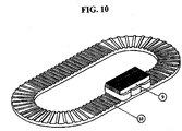
- FIG. 10 is a perspective view showing an example of a linear motor, which is implemented using a stator having a curved portion, according to an embodiment of the present invention.
- the structure of the mover and the stator according to the present invention can be applied when the stator for the motion of the mover is configured to have a curved track, as shown in FIG. 10 .
- FIG. 11 is a view illustrating an inner rotor type motor, in which permanent magnets 12 are located in a stator, according to a disclosure.
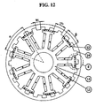
- FIG. 12 is a view illustrating an outer rotor type motor, in which permanent magnets 12 are located in a stator, according to a disclosure.
- the stator of the rotary motor includes stator phase coils 11, a permanent magnet 12, and a stator core 13.
- the rotor of the rotary motor includes a rotor core 14. Teeth, which repeat in the circumferential direction, are provided in the end of the rotor core 14.
- the rotor which is the rotary moving body shown in FIG. 11
- the rotor which is a rotary moving body shown in FIG. 12
- FIGS. 11 and 12 are based on the concepts of FIGS. 4 and 5 .
- Each of the structures includes an odd number of permanent magnets, which includes first permanent magnets, having the same polarities, provided at the left and right edges of the end of each stator tooth (refer to D/E), and at least one second permanent magnet, having a polarity opposite to those of the first permanent magnets, arranged between the first permanent magnets.
- first permanent magnets having the same polarities, provided at the left and right edges of the end of each stator tooth (refer to D/E)
- at least one second permanent magnet having a polarity opposite to those of the first permanent magnets, arranged between the first permanent magnets.
- FIG. 15 - relating to the disclosures with the exception of Fig. 15E , second from left, which relates to an embodiment of the present invention - the end of each stator tooth (refer to D/E) may be modified and implemented in various ways.
- permanent magnets having the same polarities, may be provided in the end of each stator tooth, and may be arranged on the left and right sides of a single protrusion of the end of the stator tooth (refer to the second drawings from the right side in D and E of FIG. 15 ), or a single permanent magnet may be provided between two protrusions (refer to the third drawings from the right side in D and E of FIG. 15 ).
- permanent magnets 12, having the same polarities may be provided in the end of the rotor at respective locations between the teeth the end of the rotor, which repeat in the circumferential direction (refer to the rightmost drawings from the right side in D and E of FIG. 15 ).
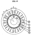
- FIG. 13 is a view illustrating an inner rotor type motor, in which permanent magnets 12 are located in a rotor, according to a disclosure.
- FIG. 14 is a view illustrating an outer rotor type motor, in which permanent magnets 12 are located in a rotor, according to a disclosure.
- FIGS. 13 and 14 show the structures in each of which permanent magnets 12 are arranged in the rotor.
- the structures are based on the concepts of FIGS. 6 and 7 .
- the permanent magnets 12, having the same polarities, may be provided in the end of the rotor (refer to F/G) at respective locations between the teeth of the end of the rotor, which repeat in the circumferential direction.
- the end of each stator tooth (refer to F/G) may be modified and implemented in various ways.
- the permanent magnets 12, having the same polarities may be provided in the end of each stator tooth and, in particular, may be arranged on the left and right sides of at least one protrusion of the end of the stator (refer to the second drawings from the right side in F and G of FIG. 15 ), or may be provided at respective locations between a plurality of protrusions (refer to the third drawings from the right side in F and G of FIG. 15 ).
- an odd number of permanent magnets which includes first permanent magnets, having the same polarities, provided in the end of each stator tooth (refer to F/G) at the left and right edges of the end of the stator, and at least one permanent magnet, having a polarity opposite to those of the permanent magnets, provided at respective locations between the permanent magnets, for example, one or three permanent magnets, may be provided.
- teeth which repeat and have a protruding shape, are formed in the end of the rotor.
- the stator in order to generate the torque using the three-phase back-electromotive force, which is caused by the rotor phase coils 11, the stator includes stator teeth, the number of which is a multiple of three, which are arranged at the same pitch in the rotary motion direction, that is, in the circumferential direction, regardless of the type thereof, that is, an inner rotor type or an outer rotor type.
- the end of each stator tooth may be implemented to have various lengths.
- the tooth angle ⁇ 22.5 degrees
- tooth angle ⁇ 22.5 degrees
- stator teeth may be implemented in various ways to include stator teeth, the number of which is a multiple of 3.
- the teeth angle ⁇ and the arrangement angle ⁇ which are described above, are integrally determined according to the number of stator teeth, and thus the stator teeth and the permanent magnets can be arranged at predetermined pitches.
- the torque pulsation can be decreased by changing the width Wp of each permanent magnet 12, the width Wt of each rotor tooth, or the shape of the rotor, the stator or the permanent magnet 12.
- the degradation of the permanent magnets, attributable to the heat that is generated by the stator phase coils 11, can be prevented from occurring.
- the concern about scattering of the permanent magnets during operation can be alleviated.
- portions to which permanent magnets are attached in the rotor or in the stator are selectively replaced with iron core teeth as shown in FIG. 15 , the number of permanent magnets that are used can be reduced, but this does not belong to the present invention.
- the laminated iron core of the stator or rotor of the above-described rotary motor may be formed by coupling two or more divided iron cores to each other.
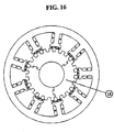
- the rotor of the inner rotor type motor may be formed by coupling three divided iron cores, shown in FIG. 16 also relating to a disclosure, to each other.
- Each of the divided iron cores 15 of the rotor has a protrusion and a depression, and the protrusion of one divided iron core is coupled to the depression of another divided iron core, so that the divided iron cores can be securely coupled to each other even when rotary motion is performed.
- stator of the inner rotor type motor shown in FIG. 11 belonging to a disclosure, may be formed by coupling three or nine divided iron cores 16, shown in FIG. 17 or 18 , to each other.
- Fig. 17 and 18 relate to disclosures.
- stator or rotor may be formed by coupling various numbers of iron cores, such as two, four, five or six divided iron cores, in addition to the three or nine divided iron cores.
- the rotor of the outer rotor type motor may be formed by coupling three divided iron cores, shown in FIG. 19 , to each other.
- Fig. 19 also relating to a disclosure.
- Each of the divided iron cores 17 of the rotor has a protrusion and a depression, and the protrusion of one divided iron core is coupled to the depression of another divided iron core, so that the divided iron cores can remain securely coupled to each other even when rotary motion is performed.
- stator of the outer rotor type motor shown in FIG. 12 relating to a disclosure, may be formed by coupling three or nine divided iron cores 18, shown in FIG. 20 or 21 , to each other.
- Fig. 20 and 21 relating to disclosures.
- stator or rotor may also be formed by coupling various numbers of divided iron cores, such as two, four, five or six divided iron cores, in addition to the three or nine divided iron cores.
- stator or rotor When divided iron cores are applied to the stator or rotor as described above, the stator or rotor can be more easily manufactured than a stator or rotor that is formed as a single body. Furthermore, in the case where any abrasion occurs, only a portion of the stator or rotor need be replaced, without requiring replacement of the entire stator or rotor, thus conferring an economic advantage in use.
- FIG. 22 is a view illustrating the case where the outer rotor type motor of FIG. 12 according to a disclosure is mounted in the wheel of a vehicle.
- the permanent magnets 12 are attached to the stator as described above, so that there is no concern about scattering of the permanent magnets.
- the vehicle includes all of an automobile, an electric rail car, a train, and the like, which have drive equipment using wheels.
- FIG. 23 is a view illustrating a disclosure, in which permanent magnets are applied to mover teeth having an uneven surface structure.
- the present disclosure may be configured such that two protrusions are formed in the end of each tooth of the mover core 1 of a mover, which moves relative to a stator core 5, and such that permanent magnets 3, having the same polarity, for example, either N or S polarity, are provided in the right and left ends of the end of the tooth and in a depression formed between the protrusions.
- FIG. 24 is a view illustrating another disclosure, in which permanent magnets are applied to mover teeth having an uneven surface structure.
- the present disclosure may be configured such that three protrusions are formed in the end of each tooth of the mover core 1 of a mover, which moves relative to a stator core 5, and such that permanent magnets 3, having the same polarity, for example, either N or S polarity, are provided in depressions formed between the protrusions.
- another disclosure may be configured such that a plurality of protrusions is formed in the end of each tooth of a mover core 1, and such that respective permanent magnets 3, having the same polarity, for example, either N or S polarity, are provided on the right and left sides of each protrusion.
- two permanent magnets having opposite polarities may be provided on the right and left sides of the central protrusion of a mover.
- the present disclosure may be configured such that a single central protrusion is formed in the end of each tooth of the mover core 1 of the mover, which moves relative to a stator core 5, and such that permanent magnet pairs 3, that is, first permanent magnet and second magnet, having opposite polarities, are arranged on the right and left sides of the central protrusion.
- the present disclosure may have a structure of N-S-protrusion-S-N or S-N-protrusion-N-S.
- permanent magnet pairs having opposite polarities may be provided on the right and left sides of each protrusion. Although two permanent magnet pairs have been described above as an example, three or more permanent magnet pairs may be arranged on the right and left sides of protrusions. For example, when the protrusion structure of FIG. 23 is applied, a structure of N-S-protrusion-S-N-protrusion-N-S or a structure of S-N-protrusion-N-S-protrusion-S-N may be implemented.
- FIG. 26 is a view illustrating a flux reversal motor, to which two mover modules are applied, according to a disclosure.
- the flux reversal motor of FIG. 26 has a structure in which two three-phase movers, having three phase windings, are arranged.
- the movers are spaced apart from each other by a pole pitch of ⁇ p , and the phase windings, which are formed by coils wound around the mover teeth of the first and second movers 'Mover 1' and 'Mover 2' are wound in the opposite directions. Thanks to the above-described arrangement, an advantage of reducing the imbalance between the back-electromotive forces that are induced by the respective phase windings can be provided.
- the present invention is not limited to a structure in which three mover teeth are provided in each mover, but may include a structure in which a number of mover teeth, corresponding to a multiple of three, and phase windings, which are provided in the respective mover teeth, are provided in order to induce three-phase back-electromotive force.
- the pulsation of the thrust and the pulsation of the normal force are decreased by eliminating the end-effect, such as the generation of leakage magnetic flux, through appropriate arrangement of the above-described movable permanent magnets.
- the detent force can be decreased by appropriately applying the skew structure to the mover or stator core, thus ensuring low noise/low vibration, high speed, high precision, and high thrust motion.
- the linear or rotary flux reversal motor according to the present invention can ensure the above-described low noise/low vibration, high speed, high precision, and high thrust motion, so that it can be used in various types of application equipment, such as a compressor, a processing machine and industrial electric equipment, in which linear or rotary motion is required, as well as in application fields such as a field in which low-speed direct drive or precision position control is required, or a field in which it is required to directly drive the wheels of vehicles, in which high-speed operation is required.
- application equipment such as a compressor, a processing machine and industrial electric equipment, in which linear or rotary motion is required, as well as in application fields such as a field in which low-speed direct drive or precision position control is required, or a field in which it is required to directly drive the wheels of vehicles, in which high-speed operation is required.
Landscapes
- Engineering & Computer Science (AREA)
- Power Engineering (AREA)
- Physics & Mathematics (AREA)
- Chemical & Material Sciences (AREA)
- Combustion & Propulsion (AREA)
- Electromagnetism (AREA)
- Linear Motors (AREA)
Description
- The present invention relates generally to a flux reversal motor and, more particularly, to a linear motor, which can decrease the number of permanent magnets that are used, can facilitate magnetization using permanent magnets having the same polarities, can move at high speed because thrust is increased, and can realize low noise/low vibration and high precision position control by decreasing the pulsation of thrust and normal force, and to a rotary motor, which is based on the concept of the linear motor, and which can prevent the degradation of the permanent magnets from occurring because the permanent magnets are provided in a rotor, can prevent scattering from occurring because the permanent magnets are provided in a stator, and can be effectively manufactured by applying divided iron cores to a stator or rotor.
- A conventional linear motor representatively includes a permanent magnet linear synchronous motor, and is widely used for the purpose of attaining high speeds, rapid acceleration and deceleration, and high precision position control. However, a conventional permanent magnet linear synchronous motor is formed to have an actuation coil structure, in which permanent magnets are located in a stator, so that it has disadvantages in that the manufacturing cost thereof is inevitably increased because the movement distance is increased and, thus, the number of permanent magnets that are used is increased, and in that the pulsation of thrust and normal force are caused due to the end-effect, which occurs at the ends of the entry and exit of a mover. Furthermore, some applications of the conventional permanent magnet linear synchronous motor may be limited by the influence of the leakage magnetic flux, which is generated by the permanent magnets attached to the stator, on the surroundings.
- United States Patent No.
4,713,570 , in its embodiment ofFig. 8 , discloses a flux reversal motor comprising a mover moving linearly relative to a stator and a plurality of permanent magnets. Further is disclosed a flux reversal motor comprising a moving body and a mover core. - Accordingly, the present invention has been made keeping in mind the above problems occurring in the prior art, and the present invention is directed to provide a flux reversal linear motor, which can reduce the manufacturing cost thereof because the number of permanent magnets that are used is decreased, which can facilitate magnetization by enabling movable permanent magnets, having the same polarities, to be provided in a mover, which can decrease the pulsation of thrust and normal force by preventing an end-effect, such as the generation of leakage magnetic flux, from occurring through the appropriate arrangement of the movable permanent magnets, and which can also decrease detent force by applying a predetermined skew structure to a mover or stator core, thus realizing low noise/low vibration, high speeds, high precision, and high thrust motion.
- Furthermore, the present invention is directed to provide a flux reversal rotary motor, which is based on the concept of the linear motor, and which can decrease the number of permanent magnets that are used, can facilitate magnetization, can increase the torque, can decrease the pulsation of the torque, can prevent the degradation of permanent magnets, attributable to the heat that is generated by stator coils, from occurring because the permanent magnets are provided in the rotor, and can be economically and easily manufactured by applying divided iron cores to the stator or rotor.
- First, the features of the present invention are summarized. In order to accomplish the above object, the present invention provides a flux reversal motor according to
claim 1. - The permanent magnets may be configured to have any of the triangular, rectangular, square, trapezoidal, pentagonal, and circular shapes, wherein at least one edge of each of the permanent magnets may be formed to have a round shape. The end of the protrusion may be configured to have any of rectilinear, round, angled, and chamfered shapes. The ends of teeth of the stator may be configured to have any of rectilinear, round, angled, and chamfered shapes.
- The permanent magnets may be configured in such a way that, when other elements of the mover are completed,
predetermined magnets are attached to predetermined locations and are then magnetized. - The iron cores of the stator or of the mover may be laminated such that the stator teeth and the mover teeth are opposite each other so as to have a predetermined skew structure.
- The stator may have a curved track for the motion of the mover.
- The mover may include mover teeth, the number of which is a multiple of three, which are arranged at an identical pitch in a motion direction. The ends of the mover teeth may have a length three or any odd number of times as great as the pole pitch of each of the permanent magnets in the motion direction.
- The above and other objects, features and advantages of the present invention will be more clearly understood from the following detailed description taken in conjunction with the accompanying drawings, in which:
-
FIG. 1 is a view illustrating the mover and stator of a linear motor according to an embodiment of the present invention; -
FIG. 2 is a view illustrating various embodiments of (A) the central protrusions of mover teeth, (B) permanent magnets, and (C) stator teeth; -
FIG. 3 is a conceptual diagram illustrating the permanent magnet magnetization of the mover; -
FIG. 4 is a view illustrating a disclosure not belonging to the present invention ("disclosure" in the following) in which three permanent magnets are applied to the mover; -
FIG. 5 is a view illustrating a disclosure in which five permanent magnets are applied to the mover; -
FIG. 6 is a disclosure illustrating a first example of using permanent magnets in a stator and forming a mover to have a prominence and depression structure; -
FIG. 7 is a disclosure illustrating a second example of using permanent magnets in a stator and forming a mover to have a prominence and depression structure; -
FIG. 8 is a perspective view of the linear motor according to the embodiment of the present invention; -
FIG. 9 is a view showing the structure of the linear motor according to the embodiment of the present invention, in which a skew structure is applied to a mover core; -
FIG. 10 is a perspective view showing an example of a linear motor, which is implemented using a stator having a curved portion, according to an embodiment of the present invention; -
FIG. 11 is a view illustrating an inner rotor type motor, in which permanent magnets are located in a stator, according to a disclosure; -
FIG. 12 is a view illustrating an outer rotor type motor, in which permanent magnets are located in a stator, according to a disclosure; -
FIG. 13 is a view illustrating an inner rotor type motor, in which permanent magnets are located in a rotor, according to a disclosure; -
FIG. 14 is a view illustrating an outer rotor type motor, in which permanent magnets are located in a rotor, according to a disclosure; -
FIG. 15 is a view illustrating examples in which permanent magnets are applied, in various ways, to the stator or rotor of inner rotor type or outer rotor type motor. The example ofFig. 15E , second from left, relates to an embodiment of the present invention. The remainder ot theFigure 15 are disclosures. -
FIG. 16 is a view illustrating the case in which a triple-divided iron core is applied to the rotor of the inner rotor type motor according to a disclosure; -
FIG. 17 is a view illustrating the case in which a non-uple-divided iron core is applied to the stator of the inner rotor type motor according to a disclosure; -
FIG. 18 is a view illustrating the case in which the triple-divided iron core is applied to the stator of the inner rotor type motor according to a disclosure; -
FIG. 19 is a view illustrating the case in which the triple-divided iron core is applied to the rotor of the outer rotor type motor according to a disclosure; -
FIG. 20 is a view illustrating the case where the non-uple-divided iron core is applied to the stator of the outer rotor type motor according to a disclosure; -
FIG. 21 is a view illustrating the case where the triple-divided iron core is applied to the stator of the outer rotor type motor according to a disclosure; -
FIG. 22 is a view illustrating the case where the outer rotor type motor according to a disclosure is mounted to a wheel of a vehicle; -
FIG. 23 is a view illustrating a disclosure, in which permanent magnets are applied to mover teeth having an uneven surface structure; -
FIG. 24 is illustrating a disclosure, in which permanent magnets are applied to mover teeth having an uneven surface structure; -
FIG. 25 is a view illustrating a disclosure, in which two permanent magnets, the polarities of which are opposite each other, are arranged on the right and left sides of the central protrusion of a mover; -
FIG. 26 is a view illustrating a flux reversal motor, to which two mover modules are applied, according to a disclosure. - Preferred embodiments of the present invention are described in detail below with reference to particular accompanying drawings and details described in the accompanying drawings, but the scope of the present invention is defined by the claims. The same reference numerals, which are used throughout the different drawings, designate the same or similar components.
-
FIG. 1 is a view illustrating the mover and stator of a linear motor according to an embodiment of the present invention. Referring toFIG. 1 , the mover of the linear motor according to the embodiment of the present invention includes amover core 1, moverteeth 2,permanent magnets 3, andmover phase coils 4. The stator of the linear motor according to the embodiment of the present invention includes astator core 5 andstator teeth 6. - When an appropriate amount of current is applied to the
mover phase coils 4, which are formed by winding the coil around themover teeth 2, as shown inFIG. 1 (X: inward direction, ⊙: outward direction), the flow of magnetic flux that is generated by thepermanent magnets 3 varies according to variation in the relative locations between the mover and the stator, and thus the thrust is generated. Accordingly, the mover, which is a linearly moving body, moves linearly relative to the stator. - In particular, in the present invention, the
permanent magnets 3, having the same polarities, are provided in the end of eachmover tooth 2, as shown inFIG. 1 . In greater detail, thepermanent magnets 3 are arranged on the left and right sides of the central protrusion A of the end of the mover tooth. In this case, in order to generate the thrust using three-phase back-electromotive force, which is caused by the mover phase coils 4, the mover includesmover teeth 2, the number of which is a multiple of three, which are arranged at the same pitch in the motion direction. In this case, themover teeth 2 are arranged at the pitch γ. This means that themover teeth 2 are arranged at intervals of 120 degrees, so that the back-electromotive force, which is necessary for linear motion, can be appropriately generated due to the moving effect of thepermanent magnets 3. The width Wp of eachpermanent magnet 3 and the width Wt of eachstator tooth 6 may be designed to be smaller or greater than the pole pitch τp of eachpermanent magnet 3, which is the width of each central protrusion (A). For example, the end of eachmover tooth 2 may be designed to be three time as great as the pole pitch of eachpermanent magnet 3 in the motion direction by arranging thestator teeth 6 at a pitch of 2 τp and setting the width Wp of eachpermanent magnet 3 and the width Wt of eachstator tooth 6 to τp. -
FIG. 2 is a view illustrating various embodiments of (A) the central protrusions ofmover teeth 2, (B) permanent magnets, and (C) stator teeth. As shown inFIG. 2 , the end of a central protrusion (A), which is located between twopermanent magnets 3, may be configured to have any of various shapes, such as a rectilinear shape, a round shape, an angled shape or a chamfered shape. Furthermore, thepermanent magnets 3 may have a rectangular, regular triangular, trapezoidal or pentagonal shape. In addition, thepermanent magnets 3 may have a triangular shape or a circular shape. In the case where thepermanent magnets 3 have an angled shape, such as a triangular, rectangular, regular triangular, trapezoidal or pentagonal shape, at least one edge of each of thepermanent magnets 3 may be formed to have a round shape, as shown inFIG. 2 . The ends of the stator teeth 6 (C) may also be configured to have any of various shapes, such as a rectilinear shape, a round shape, an angled shape, and a chamfered shape, as shown inFIG. 2 . - In the linear motor according to the present invention, constructed as described above, the movable
permanent magnets 3 are provided in the mover, so that the number of permanent magnets that are used is decreased compared to when a number of permanent magnets proportional to the movement distance is provided in the existing stator permanent magnet, by which the manufacturing cost can be reduced. - Furthermore, when the movable
permanent magnets 3, themover teeth 2, and thestator teeth 6 are formed to have predetermined shapes and are appropriately arranged as described above, the sharp variation in reluctance is controlled and the leakage magnetic flux is reduced, and the end-effect is eliminated, so that the pulsation of the thrust and the normal force can be decreased. - Furthermore, in the present invention, as shown in
FIG. 1 , magnetization can be easily realized because thepermanent magnets 3 having the same polarities are used in the mover. That is, in the present invention, there is no difficulty in manufacturing, unlike the existing method in which the attatchment of permanent magnets, which are separately magnetized and have polarities different from each other, are individually conducted. Accordingly, in the present invention, as shown inFIG. 3 , thepermanent magnets 3 can be easily magnetized in such a way that themover core 1,permanent magnets 3, which are not magnetized, and the mover phase coils 4 are securely assembled to each other through encapsulation usingencapsulation resin 7, and then magnetization is performed on thepermanent magnets 3, which are not magnetized, using apredetermined magnetization yoke 8. - As shown in
FIG. 4 relating to a disclosure, the respectivepermanent magnets 3, which are arranged at the left and right edges of the end of eachmover tooth 2, and a single permanent magnet, having a polarity opposite to those of thepermanent magnets 3, may be used together at the location of each central protrusion (A), described with reference toFIG. 1 . Furthermore, as shown inFIG. 5 relating to a disclosure, the respectivepermanent magnets 3, which are arranged at the left and right edges of the end of eachmover tooth 2, and three permanent magnets, which includes two permanent magnets having polarities opposite to those of thepermanent magnets 3, may be used together at the location of each central protrusion (A). For example, inFIG. 4 , the permanent magnets, which are attached to the end of eachmover tooth 2, may have polarities of N-S-N or S-N-S. Furthermore, inFIG. 5 , the permanent magnets, which are attached to the end of eachmover tooth 2, may have polarities of N-S-N-S-N or S-N-S-N-S. That is, instead of each central protrusion (A), an odd number of permanent magnets, which include first permanent magnets, which are provided at both edges of the end of eachmover tooth 2, and at least one second permanent magnet having a polarity opposite to those of the first permanents, are used. In this case, a stronger thrust is ensured, and thus applicability to high-speed application systems can be realized. - Meanwhile, in order to prevent the degradation of the characteristics of the
permanent magnets 3 from occurring due to the heat generated by the mover phase coils 4, if necessary, permanent magnets may be arranged in the stator, as shown inFIGS. 6 and7 relating to disclosures. -
FIG. 6 is illustrating a disclosure of using permanent magnets in a stator and forming a mover to have a prominence and depression structure. As shown inFIG. 6 , the configuration may be made such that a plurality of permanent magnets, having the same polarities, are provided in the end of the stator at respective locations between theteeth 6 of thestator core 5, which repeat in the motion direction. In this case, the mover may have an uneven surface structure in which, in the end of each tooth of themover core 1, two protrusions are formed in the end of each tooth, and one de- pression is formed between the two protrusions. -
FIG. 7 is illustrating a second disclosure using permanent magnets in a stator and forming a mover to have a prominence and depression structure. As shown inFIG. 7 , the configuration may be made such that a plurality of permanent magnets, having the same polarities, are provided in the end of the stator at respective locations between theteeth 5 of thestator core 5, which repeat in the motion direction. In this case, the mover may have an uneven surface structure in which, in the end of each tooth of themover core 1, three protrusions are formed in the end of each tooth, and depressions are formed between the three protrusions. Furthermore, the mover may have an uneven surface structure in which three or more protrusions are provided, and depressions are formed between the three or more protrusions. - As described above, in the flux reversal linear motor according to a disclosure, an odd number of permanent magnets can be provided at the location of the central protrusion (A) of each
mover tooth 2, and the permanent magnets can be arranged in the stator as well as in the mover. In addition, themover teeth 2 or thestator teeth 6 can be modified and implemented in various ways to conform to requirements for various application systems. - The overall perspective view of the linear motor, which is implemented in various ways, is shown in
FIG. 8 . When an appropriate amount of power, such as three-phase current, is supplied to the mover phase coils 4, the mover receives thrust in response to the operation of themover core 1 and thepermanent magnets 3, which are opposite thestator core 5, and then moves linearly along the path of the stator. - In this case, in order to further decrease the pulsation attributable to the detent force and the end-effect, stator or mover cores may be laminated such that the
mover teeth 2 and thestator teeth 6 are opposite each other so as to have a predetermined skew structure, as shown inFIG. 9 . InFIG. 9 , the skew length corresponds to the period of the detent force. The period of the detent force may vary according to the pitch of each of theteeth 2/6. When the skew structure is applied as described above, applicability to various application systems for which low noise/low vibration, high speeds, high precision, and high thrust are required can be realized. -
FIG. 10 is a perspective view showing an example of a linear motor, which is implemented using a stator having a curved portion, according to an embodiment of the present invention. The structure of the mover and the stator according to the present invention can be applied when the stator for the motion of the mover is configured to have a curved track, as shown inFIG. 10 . - Meanwhile, an example in which the structural concept of the above-described mover and stator is applied to a rotary flux reversal motor is described below.
-
FIG. 11 is a view illustrating an inner rotor type motor, in whichpermanent magnets 12 are located in a stator, according to a disclosure. -
FIG. 12 is a view illustrating an outer rotor type motor, in whichpermanent magnets 12 are located in a stator, according to a disclosure. - As shown in
FIGS. 11 and12 , the stator of the rotary motor according to a disclosure includes stator phase coils 11, apermanent magnet 12, and astator core 13. The rotor of the rotary motor includes arotor core 14. Teeth, which repeat in the circumferential direction, are provided in the end of therotor core 14. - When an appropriate amount of three-phase current is applied to the stator phase coils 11, the rotor, which is the rotary moving body shown in
FIG. 11 , rotates internally relative to the stator in the circumferential direction, whereas the rotor, which is a rotary moving body shown inFIG. 12 , rotates externally relative to the stator in the circumferential direction. - In particular, the structures of
FIGS. 11 and12 are based on the concepts ofFIGS. 4 and5 . Each of the structures includes an odd number of permanent magnets, which includes first permanent magnets, having the same polarities, provided at the left and right edges of the end of each stator tooth (refer to D/E), and at least one second permanent magnet, having a polarity opposite to those of the first permanent magnets, arranged between the first permanent magnets. As shown in (D) and (E) ofFIG. 15 - relating to the disclosures with the exception ofFig. 15E , second from left, which relates to an embodiment of the present invention - the end of each stator tooth (refer to D/E) may be modified and implemented in various ways. For example, permanent magnets, having the same polarities, may be provided in the end of each stator tooth, and may be arranged on the left and right sides of a single protrusion of the end of the stator tooth (refer to the second drawings from the right side in D and E ofFIG. 15 ), or a single permanent magnet may be provided between two protrusions (refer to the third drawings from the right side in D and E ofFIG. 15 ). Furthermore,permanent magnets 12, having the same polarities, may be provided in the end of the rotor at respective locations between the teeth the end of the rotor, which repeat in the circumferential direction (refer to the rightmost drawings from the right side in D and E ofFIG. 15 ). -
FIG. 13 is a view illustrating an inner rotor type motor, in whichpermanent magnets 12 are located in a rotor, according to a disclosure.FIG. 14 is a view illustrating an outer rotor type motor, in whichpermanent magnets 12 are located in a rotor, according to a disclosure. -
FIGS. 13 and14 show the structures in each of whichpermanent magnets 12 are arranged in the rotor. The structures are based on the concepts ofFIGS. 6 and7 . Thepermanent magnets 12, having the same polarities, may be provided in the end of the rotor (refer to F/G) at respective locations between the teeth of the end of the rotor, which repeat in the circumferential direction. As shown in (F) and (G) ofFIG. 15 , the end of each stator tooth (refer to F/G) may be modified and implemented in various ways. For example, thepermanent magnets 12, having the same polarities, may be provided in the end of each stator tooth and, in particular, may be arranged on the left and right sides of at least one protrusion of the end of the stator (refer to the second drawings from the right side in F and G ofFIG. 15 ), or may be provided at respective locations between a plurality of protrusions (refer to the third drawings from the right side in F and G ofFIG. 15 ). - Furthermore, as in the first drawings in (F) and (G) of
FIG. 15 , an odd number of permanent magnets, which includes first permanent magnets, having the same polarities, provided in the end of each stator tooth (refer to F/G) at the left and right edges of the end of the stator, and at least one permanent magnet, having a polarity opposite to those of the permanent magnets, provided at respective locations between the permanent magnets, for example, one or three permanent magnets, may be provided. In this case, teeth, which repeat and have a protruding shape, are formed in the end of the rotor. - In the above-described rotary motor, shown in
FIGS. 11 to 14 , in order to generate the torque using the three-phase back-electromotive force, which is caused by the rotor phase coils 11, the stator includes stator teeth, the number of which is a multiple of three, which are arranged at the same pitch in the rotary motion direction, that is, in the circumferential direction, regardless of the type thereof, that is, an inner rotor type or an outer rotor type. In this case, the end of each stator tooth may be implemented to have various lengths. - For example,
FIGS. 11 and12 show the case in which nine stator teeth (three stator teeth for each of three phases) are present in the stator, and the tooth angle β = 3 τp. In this case, the pole pitch τp of eachpermanent magnet 12 = 22.5/3 = 7.5 degrees, the tooth angle β = 22.5 degrees, and the arrangement angle α = 120/3 = 40 degrees.FIGS. 13 and14 shows the case in which twelve stator teeth are present in the stator (four stator teeth for each of three phases), and the tooth angle β = 5 τp. In this case, the pole pitch τp of eachpermanent magnet 12 = 18/4 = 4.5 degrees, tooth angle β = 22.5 degrees, and arrangement angle α = 120/4 = 30 degree. - The case where nine or twelve stator teeth are present in the stator, as shown in
FIGS. 11 and12 , has been described above. Alternatively, as a further disclosure, the stator may be implemented in various ways to include stator teeth, the number of which is a multiple of 3. As described above, the teeth angle β and the arrangement angle α, which are described above, are integrally determined according to the number of stator teeth, and thus the stator teeth and the permanent magnets can be arranged at predetermined pitches. - In addition, the torque pulsation can be decreased by changing the width Wp of each
permanent magnet 12, the width Wt of each rotor tooth, or the shape of the rotor, the stator or thepermanent magnet 12. - In one of the present disclosures, when permanent magnets are included in the rotor as described above, the degradation of the permanent magnets, attributable to the heat that is generated by the stator phase coils 11, can be prevented from occurring. When permanent magnets are included in the stator as described above, the concern about scattering of the permanent magnets during operation can be alleviated. Furthermore, when portions to which permanent magnets are attached in the rotor or in the stator are selectively replaced with iron core teeth as shown in
FIG. 15 , the number of permanent magnets that are used can be reduced, but this does not belong to the present invention. - Meanwhile, the laminated iron core of the stator or rotor of the above-described rotary motor may be formed by coupling two or more divided iron cores to each other.
- The rotor of the inner rotor type motor, shown in
FIG. 11 relating to a disclosure, may be formed by coupling three divided iron cores, shown inFIG. 16 also relating to a disclosure, to each other. Each of the dividediron cores 15 of the rotor has a protrusion and a depression, and the protrusion of one divided iron core is coupled to the depression of another divided iron core, so that the divided iron cores can be securely coupled to each other even when rotary motion is performed. - In the same manner, the stator of the inner rotor type motor, shown in
FIG. 11 belonging to a disclosure, may be formed by coupling three or nine dividediron cores 16, shown inFIG. 17 or18 , to each other.Fig. 17 and18 relate to disclosures. - The above-described stator or rotor may be formed by coupling various numbers of iron cores, such as two, four, five or six divided iron cores, in addition to the three or nine divided iron cores.
- Furthermore, the rotor of the outer rotor type motor, shown in
FIG. 12 relating to a disclosure, may be formed by coupling three divided iron cores, shown inFIG. 19 , to each other.Fig. 19 also relating to a disclosure. Each of the dividediron cores 17 of the rotor has a protrusion and a depression, and the protrusion of one divided iron core is coupled to the depression of another divided iron core, so that the divided iron cores can remain securely coupled to each other even when rotary motion is performed. - In the same manner, the stator of the outer rotor type motor, shown in
FIG. 12 relating to a disclosure, may be formed by coupling three or nine dividediron cores 18, shown inFIG. 20 or21 , to each other.Fig. 20 and21 relating to disclosures. - The above-described stator or rotor may also be formed by coupling various numbers of divided iron cores, such as two, four, five or six divided iron cores, in addition to the three or nine divided iron cores.
- When divided iron cores are applied to the stator or rotor as described above, the stator or rotor can be more easily manufactured than a stator or rotor that is formed as a single body. Furthermore, in the case where any abrasion occurs, only a portion of the stator or rotor need be replaced, without requiring replacement of the entire stator or rotor, thus conferring an economic advantage in use.
-
FIG. 22 is a view illustrating the case where the outer rotor type motor ofFIG. 12 according to a disclosure is mounted in the wheel of a vehicle. - When the outer rotor type motor according to a disclosure, which is implemented in various ways, is used to drive the wheel of a vehicle, the
permanent magnets 12 are attached to the stator as described above, so that there is no concern about scattering of the permanent magnets. Here, the vehicle includes all of an automobile, an electric rail car, a train, and the like, which have drive equipment using wheels. -
FIG. 23 is a view illustrating a disclosure, in which permanent magnets are applied to mover teeth having an uneven surface structure. - Referring to
FIG. 23 , the present disclosure may be configured such that two protrusions are formed in the end of each tooth of themover core 1 of a mover, which moves relative to astator core 5, and such thatpermanent magnets 3, having the same polarity, for example, either N or S polarity, are provided in the right and left ends of the end of the tooth and in a depression formed between the protrusions. -
FIG. 24 is a view illustrating another disclosure, in which permanent magnets are applied to mover teeth having an uneven surface structure. - Referring to
FIG. 24 , the present disclosure may be configured such that three protrusions are formed in the end of each tooth of themover core 1 of a mover, which moves relative to astator core 5, and such thatpermanent magnets 3, having the same polarity, for example, either N or S polarity, are provided in depressions formed between the protrusions. - In addition to the disclosures, shown in
FIGS. 23 and 24 , another disclosure may be configured such that a plurality of protrusions is formed in the end of each tooth of amover core 1, and such that respectivepermanent magnets 3, having the same polarity, for example, either N or S polarity, are provided on the right and left sides of each protrusion. - Furthermore, as shown in
FIG. 25 relating to a disclosure, two permanent magnets having opposite polarities may be provided on the right and left sides of the central protrusion of a mover. In greater detail, the present disclosure may be configured such that a single central protrusion is formed in the end of each tooth of themover core 1 of the mover, which moves relative to astator core 5, and such that permanent magnet pairs 3, that is, first permanent magnet and second magnet, having opposite polarities, are arranged on the right and left sides of the central protrusion. For example, the present disclosure may have a structure of N-S-protrusion-S-N or S-N-protrusion-N-S. In addition, in the protrusion structure ofFIGS. 23 and 24 as well, permanent magnet pairs having opposite polarities may be provided on the right and left sides of each protrusion. Although two permanent magnet pairs have been described above as an example, three or more permanent magnet pairs may be arranged on the right and left sides of protrusions. For example, when the protrusion structure ofFIG. 23 is applied, a structure of N-S-protrusion-S-N-protrusion-N-S or a structure of S-N-protrusion-N-S-protrusion-S-N may be implemented. - In the structures of the above-described flux reversal motors of
FIGS, 23, 24 and25 as well, the pulsation of the thrust and the attraction force can be reduced using the above-described skew. -
FIG. 26 is a view illustrating a flux reversal motor, to which two mover modules are applied, according to a disclosure. - The flux reversal motor of
FIG. 26 has a structure in which two three-phase movers, having three phase windings, are arranged. When a first mover 'Mover 1' and a second mover 2 'Mover 2' are arranged, the movers are spaced apart from each other by a pole pitch of τp, and the phase windings, which are formed by coils wound around the mover teeth of the first and second movers 'Mover 1' and 'Mover 2' are wound in the opposite directions. Thanks to the above-described arrangement, an advantage of reducing the imbalance between the back-electromotive forces that are induced by the respective phase windings can be provided. - Furthermore, the present invention is not limited to a structure in which three mover teeth are provided in each mover, but may include a structure in which a number of mover teeth, corresponding to a multiple of three, and phase windings, which are provided in the respective mover teeth, are provided in order to induce three-phase back-electromotive force.
- Furthermore, the pulsation of the thrust and the pulsation of the normal force are decreased by eliminating the end-effect, such as the generation of leakage magnetic flux, through appropriate arrangement of the above-described movable permanent magnets. In addition, the detent force can be decreased by appropriately applying the skew structure to the mover or stator core, thus ensuring low noise/low vibration, high speed, high precision, and high thrust motion.
- Furthermore, the linear or rotary flux reversal motor according to the present invention can ensure the above-described low noise/low vibration, high speed, high precision, and high thrust motion, so that it can be used in various types of application equipment, such as a compressor, a processing machine and industrial electric equipment, in which linear or rotary motion is required, as well as in application fields such as a field in which low-speed direct drive or precision position control is required, or a field in which it is required to directly drive the wheels of vehicles, in which high-speed operation is required.
Claims (9)
- A flux reversal motor, comprising:a mover moving linearly relative to a stator; the mover comprising a mover core and mover phase coils (4) which are formed by winding the coil around the mover teeth (2); anda plurality of movable permanent magnets (3), provided in the ends of each of the mover teeth (2), wherein each mover tooth (2) has at its end a single central protrusion,whereinthe permanent magnets (3) of all teeth (2) have the identical polarity, andthe movable permanent magnets (3) being arranged on left and right sides of each of said protrusions.
- The flux reversal motor as set forth in claim 1, wherein, when the movable permanent magnets (3) are configured to have any of the triangular, rectangular, square, trapezoidal, and pentagonal shape, at least one edge of each of the movable permanent magnets (3) is formed to have a round shape.
- The flux reversal motor as set forth in claim 1, wherein an end of the protrusion is configured to have any of rectilinear, round, angled, and chamfered shapes.
- The flux reversal motor as set forth in claim 1, wherein ends of teeth of the stator (6) are configured to have any of rectilinear, round, angled, and chamfered shapes.
- The flux reversal motor as set forth in claim 1, wherein iron cores of the stator or of the mover are laminated such that the stator teeth (6) and the mover teeth (2) are opposite each other so as to have a predetermined skew structure.
- The flux reversal motor as set forth in claim 1, wherein the stator has a curved track for motion of the mover.
- The flux reversal motor as set forth in claim 1, wherein the mover comprises mover teeth (2), a number of which is a multiple of three, which are arranged at an identical pitch in a motion direction.
- The flux reversal motor as set forth in claim 7, wherein the ends of the mover teeth (2) have a length three or any odd number of times as great as a pole pitch (τp) of each of the permanent magnets in the motion direction.
- A flux reversal motor, comprising
a moving body provided with movable permanent magnets (3) and a mover core, all said permanent magnets of said moving body having identical polarities, wherein in an end of each tooth (2) of the moving body, the movable permanent magnets (3) being arranged on left and right sides of a single central protrusion (A) of the end of each of the teeth (2), the flux reversal motor further including mover phase coils (4) which are formed by winding the coil around the mover teeth (2); wherein the moving body rotates internally or externally relative to the stator in a circumferential direction.
Applications Claiming Priority (2)
| Application Number | Priority Date | Filing Date | Title |
|---|---|---|---|
| KR20070067566 | 2007-07-05 | ||
| KR1020080046284A KR100996135B1 (en) | 2007-07-05 | 2008-05-19 | Low noise, high speed, high precision, high thrust flux reversing motor for linear or rotary motion systems |
Publications (3)
| Publication Number | Publication Date |
|---|---|
| EP2012414A2 EP2012414A2 (en) | 2009-01-07 |
| EP2012414A3 EP2012414A3 (en) | 2016-04-06 |
| EP2012414B1 true EP2012414B1 (en) | 2020-03-25 |
Family
ID=39811577
Family Applications (1)
| Application Number | Title | Priority Date | Filing Date |
|---|---|---|---|
| EP08011496.0A Active EP2012414B1 (en) | 2007-07-05 | 2008-06-25 | Low-noise, high-speed, high precision and high-thrust flux reversal motor for linear or rotary motion system |
Country Status (2)
| Country | Link |
|---|---|
| US (1) | US7928612B2 (en) |
| EP (1) | EP2012414B1 (en) |
Families Citing this family (25)
| Publication number | Priority date | Publication date | Assignee | Title |
|---|---|---|---|---|
| CN102160267B (en) * | 2008-08-29 | 2013-08-21 | 莫戈公司 | Permanent Magnet Stepper Motor |
| KR101065613B1 (en) * | 2009-04-13 | 2011-09-20 | 한국전기연구원 | Linear and rotary electric machine structure |
| KR101092212B1 (en) * | 2009-06-30 | 2011-12-13 | 한국전기연구원 | Double-pole pole permanent magnet electric machine |
| WO2011031250A2 (en) * | 2009-09-08 | 2011-03-17 | Moog Inc. | Stepping motors with small step intervals |
| ES2400462T3 (en) * | 2010-03-18 | 2013-04-10 | Askoll Holding S.R.L. | Motor and fan assembly for condensation clothes dryer and condensation clothes dryer containing said set |
| KR101101299B1 (en) * | 2010-04-28 | 2012-01-04 | 한국전기연구원 | Winding arrangement method of double-pole pole permanent magnet electric machine |
| US20120306298A1 (en) * | 2011-06-02 | 2012-12-06 | Samsung Electro-Mechanics Co., Ltd. | Switched reluctance motor |
| EP2819283B1 (en) * | 2012-02-20 | 2018-09-05 | Hitachi, Ltd. | Linear motor |
| JP5964633B2 (en) * | 2012-03-29 | 2016-08-03 | 山洋電気株式会社 | Tubular linear motor |
| JP6117574B2 (en) * | 2013-03-05 | 2017-04-19 | 山洋電気株式会社 | Inductor type rotary motor |
| JP6048338B2 (en) * | 2013-07-29 | 2016-12-21 | 株式会社安川電機 | Linear motor |
| CA2988383A1 (en) * | 2015-06-05 | 2016-12-08 | Aldan Asanovich Saparqaliyev | Electrical machine & electrical drive |
| FR3037450B1 (en) * | 2015-06-09 | 2017-07-21 | Cnam - Conservatoire Nat Des Arts Et Metiers | ELECTRIC FLOW SWITCHING MACHINE WITH SINGLE EXCITATION |
| US10480961B2 (en) * | 2017-01-31 | 2019-11-19 | Rockwell Automation Technologies, Inc. | Hybrid encoder system for position determination |
| CN107086755A (en) * | 2017-05-09 | 2017-08-22 | 南京航空航天大学 | Independent winding modularization permanent-magnetism linear motor |
| CN107086756A (en) * | 2017-05-09 | 2017-08-22 | 南京航空航天大学 | Low-thrust fluctuates independent winding permanent-magnetism linear motor |
| CN110371600A (en) | 2018-08-30 | 2019-10-25 | 天津京东深拓机器人科技有限公司 | Cargo transportation system and cargo delivery method |
| CN109245483B (en) * | 2018-09-19 | 2020-06-23 | 南京航空航天大学 | Bilateral alternating-pole permanent magnet linear motor without yoke part at secondary level |
| CN110014846B (en) * | 2019-01-22 | 2023-11-07 | 南京航空航天大学 | A rail transit traction system based on permanent magnet flux switching linear motor |
| WO2021251808A1 (en) * | 2020-06-10 | 2021-12-16 | Алдан Асанович САПАРГАЛИЕВ | 2vs and elliptical annular electric machines |
| JP2022012638A (en) * | 2020-07-02 | 2022-01-17 | 多摩川精機株式会社 | Ring-shaped rotor core structure for vr type resolver |
| CN113328601A (en) * | 2021-06-07 | 2021-08-31 | 苏州赛得尔智能科技有限公司 | U-shaped structure magnetic concentration type permanent magnet motor |
| US20240235286A1 (en) * | 2022-03-16 | 2024-07-11 | Jiangsu University | Single winding hybrid excitation magnetic field modulation motor and synergy excitation design method thereof |
| CN218473012U (en) * | 2022-06-30 | 2023-02-10 | 瑞声光电科技(常州)有限公司 | Direct-drive system |
| US12627209B2 (en) * | 2022-07-06 | 2026-05-12 | Nti Ag | Constant force generator |
Family Cites Families (5)
| Publication number | Priority date | Publication date | Assignee | Title |
|---|---|---|---|---|
| US4712028A (en) * | 1984-05-21 | 1987-12-08 | Sigma Instruments, Inc. | Magnetically assisted stepping motor |
| US4713570A (en) * | 1986-06-04 | 1987-12-15 | Pacific Scientific Co. | Magnetically enhanced variable reluctance motor systems |
| DE68910649T2 (en) * | 1988-11-22 | 1994-05-19 | Shinko Electric Co Ltd | Actuator with strong magnetic pushing force. |
| JP2000245128A (en) * | 1999-02-22 | 2000-09-08 | Nkk Corp | Linear synchronous motor |
| JP2005151753A (en) * | 2003-11-18 | 2005-06-09 | Canon Inc | Linear motor |
-
2008
- 2008-06-25 EP EP08011496.0A patent/EP2012414B1/en active Active
- 2008-06-26 US US12/146,752 patent/US7928612B2/en active Active
Non-Patent Citations (1)
| Title |
|---|
| None * |
Also Published As
| Publication number | Publication date |
|---|---|
| US7928612B2 (en) | 2011-04-19 |
| US20090009010A1 (en) | 2009-01-08 |
| EP2012414A2 (en) | 2009-01-07 |
| EP2012414A3 (en) | 2016-04-06 |
Similar Documents
| Publication | Publication Date | Title |
|---|---|---|
| US7928612B2 (en) | Low-noise, high-speed, high precision and high-thrust flux reversal motor for linear or rotary motion system | |
| US9172278B2 (en) | Permanent magnet type rotary electric machine and electric power steering apparatus using the same | |
| EP1198055B1 (en) | Linear motor, driving and control system thereof and manufacturing method thereof | |
| CN100594656C (en) | permanent magnet synchronous motor | |
| EP2242167B1 (en) | Structure for linear and rotary electric machines | |
| JP5609844B2 (en) | Electric motor | |
| JP5511713B2 (en) | Linear motor | |
| US9006941B2 (en) | Permanent magnet motor having teeth with fingers | |
| JP2009219199A (en) | Linear motor | |
| JP5041415B2 (en) | Axial gap type motor | |
| JP6083640B2 (en) | Permanent magnet embedded motor | |
| KR100996135B1 (en) | Low noise, high speed, high precision, high thrust flux reversing motor for linear or rotary motion systems | |
| US20080290754A1 (en) | AC Motor | |
| US10734879B2 (en) | Cornering linear motor | |
| JPH02246761A (en) | linear motor | |
| JP7507840B2 (en) | Rotating electric machine, rotating electric motor drive system, and electric vehicle | |
| EP3787154B1 (en) | Rotating electric machine, rotating electric motor drive system, and electric vehicle | |
| JP6345355B1 (en) | Linear motor | |
| JP2022119042A (en) | linear motor | |
| TWI449304B (en) | Permanent magnet operating machine | |
| JP2024006584A (en) | linear motor | |
| JP2022135254A (en) | Cylindrical linear motor | |
| JP2009171797A (en) | Stepping motor | |
| JP2007209175A (en) | Three-phase linear motor | |
| JP6408120B2 (en) | Linear motor |
Legal Events
| Date | Code | Title | Description |
|---|---|---|---|
| PUAI | Public reference made under article 153(3) epc to a published international application that has entered the european phase |
Free format text: ORIGINAL CODE: 0009012 |
|
| AK | Designated contracting states |
Kind code of ref document: A2 Designated state(s): AT BE BG CH CY CZ DE DK EE ES FI FR GB GR HR HU IE IS IT LI LT LU LV MC MT NL NO PL PT RO SE SI SK TR |
|
| AX | Request for extension of the european patent |
Extension state: AL BA MK RS |
|
| PUAL | Search report despatched |
Free format text: ORIGINAL CODE: 0009013 |
|
| AK | Designated contracting states |
Kind code of ref document: A3 Designated state(s): AT BE BG CH CY CZ DE DK EE ES FI FR GB GR HR HU IE IS IT LI LT LU LV MC MT NL NO PL PT RO SE SI SK TR |
|
| AX | Request for extension of the european patent |
Extension state: AL BA MK RS |
|
| RIC1 | Information provided on ipc code assigned before grant |
Ipc: H02K 21/20 20060101ALI20160229BHEP Ipc: H02K 41/03 20060101AFI20160229BHEP Ipc: H02K 21/22 20060101ALI20160229BHEP Ipc: H02K 1/14 20060101ALI20160229BHEP Ipc: H02K 21/44 20060101ALI20160229BHEP Ipc: H02K 1/24 20060101ALI20160229BHEP |
|
| 17P | Request for examination filed |
Effective date: 20161006 |
|
| RBV | Designated contracting states (corrected) |
Designated state(s): AT BE BG CH CY CZ DE DK EE ES FI FR GB GR HR HU IE IS IT LI LT LU LV MC MT NL NO PL PT RO SE SI SK TR |
|
| AKX | Designation fees paid |
Designated state(s): AT BE BG CH CY CZ DE DK EE ES FI FR GB GR HR HU IE IS IT LI LT LU LV MC MT NL NO PL PT RO SE SI SK TR |
|
| AXX | Extension fees paid |
Extension state: RS Extension state: BA Extension state: MK Extension state: AL |
|
| STAA | Information on the status of an ep patent application or granted ep patent |
Free format text: STATUS: EXAMINATION IS IN PROGRESS |
|
| 17Q | First examination report despatched |
Effective date: 20170421 |
|
| GRAP | Despatch of communication of intention to grant a patent |
Free format text: ORIGINAL CODE: EPIDOSNIGR1 |
|
| STAA | Information on the status of an ep patent application or granted ep patent |
Free format text: STATUS: GRANT OF PATENT IS INTENDED |
|
| INTG | Intention to grant announced |
Effective date: 20191106 |
|
| GRAS | Grant fee paid |
Free format text: ORIGINAL CODE: EPIDOSNIGR3 |
|
| GRAA | (expected) grant |
Free format text: ORIGINAL CODE: 0009210 |
|
| STAA | Information on the status of an ep patent application or granted ep patent |
Free format text: STATUS: THE PATENT HAS BEEN GRANTED |
|
| AK | Designated contracting states |
Kind code of ref document: B1 Designated state(s): AT BE BG CH CY CZ DE DK EE ES FI FR GB GR HR HU IE IS IT LI LT LU LV MC MT NL NO PL PT RO SE SI SK TR |
|
| REG | Reference to a national code |
Ref country code: GB Ref legal event code: FG4D |
|
| REG | Reference to a national code |
Ref country code: AT Ref legal event code: REF Ref document number: 1249717 Country of ref document: AT Kind code of ref document: T Effective date: 20200415 Ref country code: IE Ref legal event code: FG4D |
|
| REG | Reference to a national code |
Ref country code: DE Ref legal event code: R096 Ref document number: 602008062371 Country of ref document: DE |
|
| REG | Reference to a national code |
Ref country code: NL Ref legal event code: FP |
|
| PG25 | Lapsed in a contracting state [announced via postgrant information from national office to epo] |
Ref country code: NO Free format text: LAPSE BECAUSE OF FAILURE TO SUBMIT A TRANSLATION OF THE DESCRIPTION OR TO PAY THE FEE WITHIN THE PRESCRIBED TIME-LIMIT Effective date: 20200625 Ref country code: FI Free format text: LAPSE BECAUSE OF FAILURE TO SUBMIT A TRANSLATION OF THE DESCRIPTION OR TO PAY THE FEE WITHIN THE PRESCRIBED TIME-LIMIT Effective date: 20200325 |
|
| PG25 | Lapsed in a contracting state [announced via postgrant information from national office to epo] |
Ref country code: LV Free format text: LAPSE BECAUSE OF FAILURE TO SUBMIT A TRANSLATION OF THE DESCRIPTION OR TO PAY THE FEE WITHIN THE PRESCRIBED TIME-LIMIT Effective date: 20200325 Ref country code: SE Free format text: LAPSE BECAUSE OF FAILURE TO SUBMIT A TRANSLATION OF THE DESCRIPTION OR TO PAY THE FEE WITHIN THE PRESCRIBED TIME-LIMIT Effective date: 20200325 Ref country code: HR Free format text: LAPSE BECAUSE OF FAILURE TO SUBMIT A TRANSLATION OF THE DESCRIPTION OR TO PAY THE FEE WITHIN THE PRESCRIBED TIME-LIMIT Effective date: 20200325 Ref country code: GR Free format text: LAPSE BECAUSE OF FAILURE TO SUBMIT A TRANSLATION OF THE DESCRIPTION OR TO PAY THE FEE WITHIN THE PRESCRIBED TIME-LIMIT Effective date: 20200626 Ref country code: BG Free format text: LAPSE BECAUSE OF FAILURE TO SUBMIT A TRANSLATION OF THE DESCRIPTION OR TO PAY THE FEE WITHIN THE PRESCRIBED TIME-LIMIT Effective date: 20200625 |
|
| REG | Reference to a national code |
Ref country code: LT Ref legal event code: MG4D |
|
| PG25 | Lapsed in a contracting state [announced via postgrant information from national office to epo] |
Ref country code: RO Free format text: LAPSE BECAUSE OF FAILURE TO SUBMIT A TRANSLATION OF THE DESCRIPTION OR TO PAY THE FEE WITHIN THE PRESCRIBED TIME-LIMIT Effective date: 20200325 Ref country code: IS Free format text: LAPSE BECAUSE OF FAILURE TO SUBMIT A TRANSLATION OF THE DESCRIPTION OR TO PAY THE FEE WITHIN THE PRESCRIBED TIME-LIMIT Effective date: 20200725 Ref country code: SK Free format text: LAPSE BECAUSE OF FAILURE TO SUBMIT A TRANSLATION OF THE DESCRIPTION OR TO PAY THE FEE WITHIN THE PRESCRIBED TIME-LIMIT Effective date: 20200325 Ref country code: CZ Free format text: LAPSE BECAUSE OF FAILURE TO SUBMIT A TRANSLATION OF THE DESCRIPTION OR TO PAY THE FEE WITHIN THE PRESCRIBED TIME-LIMIT Effective date: 20200325 Ref country code: PT Free format text: LAPSE BECAUSE OF FAILURE TO SUBMIT A TRANSLATION OF THE DESCRIPTION OR TO PAY THE FEE WITHIN THE PRESCRIBED TIME-LIMIT Effective date: 20200818 Ref country code: LT Free format text: LAPSE BECAUSE OF FAILURE TO SUBMIT A TRANSLATION OF THE DESCRIPTION OR TO PAY THE FEE WITHIN THE PRESCRIBED TIME-LIMIT Effective date: 20200325 Ref country code: EE Free format text: LAPSE BECAUSE OF FAILURE TO SUBMIT A TRANSLATION OF THE DESCRIPTION OR TO PAY THE FEE WITHIN THE PRESCRIBED TIME-LIMIT Effective date: 20200325 |
|
| REG | Reference to a national code |
Ref country code: AT Ref legal event code: MK05 Ref document number: 1249717 Country of ref document: AT Kind code of ref document: T Effective date: 20200325 |
|
| REG | Reference to a national code |
Ref country code: DE Ref legal event code: R097 Ref document number: 602008062371 Country of ref document: DE |
|
| PG25 | Lapsed in a contracting state [announced via postgrant information from national office to epo] |
Ref country code: ES Free format text: LAPSE BECAUSE OF FAILURE TO SUBMIT A TRANSLATION OF THE DESCRIPTION OR TO PAY THE FEE WITHIN THE PRESCRIBED TIME-LIMIT Effective date: 20200325 Ref country code: MC Free format text: LAPSE BECAUSE OF FAILURE TO SUBMIT A TRANSLATION OF THE DESCRIPTION OR TO PAY THE FEE WITHIN THE PRESCRIBED TIME-LIMIT Effective date: 20200325 Ref country code: AT Free format text: LAPSE BECAUSE OF FAILURE TO SUBMIT A TRANSLATION OF THE DESCRIPTION OR TO PAY THE FEE WITHIN THE PRESCRIBED TIME-LIMIT Effective date: 20200325 Ref country code: DK Free format text: LAPSE BECAUSE OF FAILURE TO SUBMIT A TRANSLATION OF THE DESCRIPTION OR TO PAY THE FEE WITHIN THE PRESCRIBED TIME-LIMIT Effective date: 20200325 |
|
| REG | Reference to a national code |
Ref country code: CH Ref legal event code: PL |
|
| PLBE | No opposition filed within time limit |
Free format text: ORIGINAL CODE: 0009261 |
|
| STAA | Information on the status of an ep patent application or granted ep patent |
Free format text: STATUS: NO OPPOSITION FILED WITHIN TIME LIMIT |
|
| PG25 | Lapsed in a contracting state [announced via postgrant information from national office to epo] |
Ref country code: PL Free format text: LAPSE BECAUSE OF FAILURE TO SUBMIT A TRANSLATION OF THE DESCRIPTION OR TO PAY THE FEE WITHIN THE PRESCRIBED TIME-LIMIT Effective date: 20200325 |
|
| 26N | No opposition filed |
Effective date: 20210112 |
|
| GBPC | Gb: european patent ceased through non-payment of renewal fee |
Effective date: 20200625 |
|
| PG25 | Lapsed in a contracting state [announced via postgrant information from national office to epo] |
Ref country code: LU Free format text: LAPSE BECAUSE OF NON-PAYMENT OF DUE FEES Effective date: 20200625 |
|
| REG | Reference to a national code |
Ref country code: BE Ref legal event code: MM Effective date: 20200630 |
|
| PG25 | Lapsed in a contracting state [announced via postgrant information from national office to epo] |
Ref country code: IE Free format text: LAPSE BECAUSE OF NON-PAYMENT OF DUE FEES Effective date: 20200625 Ref country code: LI Free format text: LAPSE BECAUSE OF NON-PAYMENT OF DUE FEES Effective date: 20200630 Ref country code: CH Free format text: LAPSE BECAUSE OF NON-PAYMENT OF DUE FEES Effective date: 20200630 Ref country code: GB Free format text: LAPSE BECAUSE OF NON-PAYMENT OF DUE FEES Effective date: 20200625 |
|
| PG25 | Lapsed in a contracting state [announced via postgrant information from national office to epo] |
Ref country code: BE Free format text: LAPSE BECAUSE OF NON-PAYMENT OF DUE FEES Effective date: 20200630 Ref country code: SI Free format text: LAPSE BECAUSE OF FAILURE TO SUBMIT A TRANSLATION OF THE DESCRIPTION OR TO PAY THE FEE WITHIN THE PRESCRIBED TIME-LIMIT Effective date: 20200325 |
|
| PG25 | Lapsed in a contracting state [announced via postgrant information from national office to epo] |
Ref country code: TR Free format text: LAPSE BECAUSE OF FAILURE TO SUBMIT A TRANSLATION OF THE DESCRIPTION OR TO PAY THE FEE WITHIN THE PRESCRIBED TIME-LIMIT Effective date: 20200325 Ref country code: MT Free format text: LAPSE BECAUSE OF FAILURE TO SUBMIT A TRANSLATION OF THE DESCRIPTION OR TO PAY THE FEE WITHIN THE PRESCRIBED TIME-LIMIT Effective date: 20200325 Ref country code: CY Free format text: LAPSE BECAUSE OF FAILURE TO SUBMIT A TRANSLATION OF THE DESCRIPTION OR TO PAY THE FEE WITHIN THE PRESCRIBED TIME-LIMIT Effective date: 20200325 |
|
| PGFP | Annual fee paid to national office [announced via postgrant information from national office to epo] |
Ref country code: NL Payment date: 20250409 Year of fee payment: 18 |
|
| PGFP | Annual fee paid to national office [announced via postgrant information from national office to epo] |
Ref country code: DE Payment date: 20250327 Year of fee payment: 18 |
|
| PGFP | Annual fee paid to national office [announced via postgrant information from national office to epo] |
Ref country code: IT Payment date: 20250522 Year of fee payment: 18 |
|
| PGFP | Annual fee paid to national office [announced via postgrant information from national office to epo] |
Ref country code: FR Payment date: 20250508 Year of fee payment: 18 |