EP2012222B1 - Verfahren und System zur Erkennung von Berührungsereignissen auf der Basis redundanter Validierungen - Google Patents
Verfahren und System zur Erkennung von Berührungsereignissen auf der Basis redundanter Validierungen Download PDFInfo
- Publication number
- EP2012222B1 EP2012222B1 EP08159512.6A EP08159512A EP2012222B1 EP 2012222 B1 EP2012222 B1 EP 2012222B1 EP 08159512 A EP08159512 A EP 08159512A EP 2012222 B1 EP2012222 B1 EP 2012222B1
- Authority
- EP
- European Patent Office
- Prior art keywords
- touch
- fingerprints
- live
- fingerprint
- signals
- Prior art date
- Legal status (The legal status is an assumption and is not a legal conclusion. Google has not performed a legal analysis and makes no representation as to the accuracy of the status listed.)
- Active
Links
Images


Classifications
-
- G—PHYSICS
- G06—COMPUTING OR CALCULATING; COUNTING
- G06F—ELECTRIC DIGITAL DATA PROCESSING
- G06F3/00—Input arrangements for transferring data to be processed into a form capable of being handled by the computer; Output arrangements for transferring data from processing unit to output unit, e.g. interface arrangements
- G06F3/01—Input arrangements or combined input and output arrangements for interaction between user and computer
- G06F3/03—Arrangements for converting the position or the displacement of a member into a coded form
- G06F3/041—Digitisers, e.g. for touch screens or touch pads, characterised by the transducing means
- G06F3/043—Digitisers, e.g. for touch screens or touch pads, characterised by the transducing means using propagating acoustic waves
- G06F3/0436—Digitisers, e.g. for touch screens or touch pads, characterised by the transducing means using propagating acoustic waves in which generating transducers and detecting transducers are attached to a single acoustic waves transmission substrate
Definitions
- This invention relates generally to touch sensitive systems, and more particularly to identifying a location of a touch on a touch sensitive system that uses bending-wave touch sensors.
- Touch panels are used to provide two-dimensional coordinate information.
- One example may be an opaque track pad while another example may be a transparent touchscreen placed in front of a display such as a liquid crystal display.
- Touch panels may be based on a variety of touch technologies including four-wire and five-wire resistive, capacitive, infrared and surface acoustic wave types, as well as bending-wave touch technologies.
- bending wave touch systems may detect a touch based on a tap of an object, such as a key or finger, used to excite bending waves in a substrate. These bending waves induce electrical signals in piezoelectric elements or sensors (piezos) bonded to the substrate. These signals are captured by electronics and processed to determine a set of (X,Y) coordinates of the touch position, such as by using time-of flight methods to extract touch coordinate information from piezo signals.
- noise in the environment can cause problems, for smaller sensor sizes, such as those used in handheld applications and point-of-sale.
- Ambient noise may be detected by the touchscreen system as a false touch or series of false touches, causing confusion while actively using the touchscreen and/or by erroneously selecting options displayed on the screen.
- brief moments of corrupted signal data can be a major problem due to generation of false touch coordinates.
- WO 2006/069596 discloses a method for determining the position of impacts on an object comprising two acoustic sensors. The method comprises receiving a signal from each sensor, calculating a Fourier transform for each signal, calculating a signature function from the Fourier transforms, and comparing the signature function with predetermined reference signature functions corresponding to predetermined areas.
- WO 03/005292 discloses a dispersion corrected correlated function G(t) that is calculated from Fourier transforms of two measured bending wave signals. The function G(t) is used to calculate a touch location.
- GB 2385125 discloses a touch tablet with left and right acoustic sensors.
- a Fourier transform of a signal from the left acoustic sensor is compared to a set of templates to identify a sound location
- a Fourier transform of a signal from the right acoustic sensor is compared to a set of templates to identify another sound location.
- the two sound locations are compared and combined to increase their accuracy.
- the functional blocks are not necessarily indicative of the division between hardware circuitry.
- one or more of the functional blocks e.g., processors or memories
- the programs may be stand alone programs, may be incorporated as subroutines in an operating system, may be functions in an installed software package, and the like. It should be understood that the various embodiments are not limited to the arrangements and instrumentality shown in the drawings.
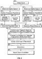
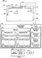
- FIG. 1 illustrates an acoustic fingerprint based touch system 100.
- the acoustic fingerprint based touch system 100 is an example of a bending-wave touch system.
- the acoustic fingerprint based touch system 100 is a system in which the bending waves are touch generated and detected in the audio frequency range of 0 - 20kHz and/or the low ultrasonic frequency range well below 1 MHz.
- Touch panel 102 has a substrate 104, such as a sheet of glass, aluminum or other material, upon which sensors 106, 108, 110 and 112 and associated traces 114, 116, 118 and 120 are mounted.
- the sensors may be piezoelectric sensors, which may be abbreviated as “piezo sensors” or simply “piezos”.
- the sensors may also be any other type of sensor that detects local motion or strain of substrate 104 such as accelerometers and strain gauges of various types.
- the sensors 106, 108, 110 and 112 may also be referred to as microphones.
- the sensors 106, 108, 110 and 112 detect sound and transmit sensor signals along the traces 114, 116, 118 and 120 which interface with a touchscreen cable 122 to convey the sensor signals to a touchscreen controller 124.
- the voltage difference between traces 114 and 120 is one analog signal generated by the anti-series combination of sensors 106 and 112.
- the anti-series combination of sensors 108 and 110 produces an analog signal corresponding to the voltage difference between traces 116 and 118.
- sensors 112 and 110 may optionally be removed such that each of sensors 106 and 108 corresponds to one analog signal. In other embodiments, more than two analog signals are produced with either altered trace interconnections and/or additional sensors (not shown). It should be understood that the sensors 106, 108, 110 and 112 are not limited to the displayed placement with respect to the substrate 104 and/or each other.
- the touch panel 102 when used as a touchscreen, is formed of a non-opaque material such as glass and is mounted in front of a display 160 that may support a graphical user interface (GUI) displaying buttons and icons or other graphical representations.
- GUI graphical user interface
- the touch panel 102 may be formed of an opaque or non-opaque material and may be located physically separate from display 160, such as to function as a track pad. It should be understood that although the touch panel 102 is primarily referred to in the following discussion, other touch panel, touchscreen and track pad designs may similarly be used.
- the touch system 100 recognizes the sound created when the substrate 104 is touched at a given position that may be described as an (X,Y) coordinate location. It should be understood that other coordinate systems may be used, such as polar coordinates with a radius and angle about the origin.
- a touch event at each different position on the substrate 104 generates a unique sound. More specifically, when a user touches a point on the substrate 104, one or more sensors 106, 108, 110 and 112 on the substrate 104 detect the sound and represent the sound as a signal. Whether the touch panel is a transparent touchscreen or an opaque or non-opaque touchpad, the principles of acoustic fingerprinting remain the same.
- An analog to digital (A/D) converter 126 within the touchscreen controller 124 receives the two analog signals produced by sensors 106-112 over the touchscreen cable 122.
- the A/D converter 126 outputs digitized signals 148 that are received by a processor module 128.
- a frequency transform module 134 may perform a frequency transform, such as a Fourier transform, or more specifically a Fast Fourier Transform (FFT), on the digitized signals 148, outputting a frequency transform data set of frequency components associated with each of the sensor signals.
- An amplitude magnitude module 130 may then extract amplitude magnitude information from each of the frequency transform signals, and a phase module 132 extracts phase information from each of the frequency transform signals.
- the processor module 128 may construct a profile or acoustic fingerprint associated with the live touch event based on the amplitude magnitude information. In another example, the processor module 128 may construct a profile or acoustic fingerprint associated with the live touch event that is based on both the amplitude magnitude information and the phase information. In yet other examples, the processor module 128 may construct the acoustic fingerprint based on the phase information or based on other information within the digitized signals 148.
- a memory 136 may store a calibration file 138 that contains a set of acoustic fingerprints to allow the user to successfully interact with the display 160.
- (X,Y) coordinate positions on the touch panel 102 are associated with the sensor signals that are generated when a series of known (X,Y) coordinate locations are touched.
- the signals may be processed and stored as acoustic fingerprints in the calibration file 138, such as first, second through N template fingerprints 140, 142 and 144.
- the signals may be processed differently to create a second calibration file 164 that is also stored in the memory 136 and contains a corresponding set of acoustic fingerprints.
- first, second through N template fingerprints 174, 176 and 178 correspond to the first, second through N template fingerprints 140, 142 and 144, respectively, and thus represent the same (X,Y) coordinate positions on the touch panel 102.
- Embodiments utilizing both of the calibration files 138 and 164 are discussed further below. It should be understood that additional calibration files may be used.
- acoustic fingerprints may also be referred without ambiguity simply as "fingerprints.”
- known location 152 may correspond to the second template fingerprint 142 and known location 154 may correspond to the Nth template fingerprint 144.
- the calibration file 138 therefore includes a plurality or collection of predetermined fingerprints or templates, each of which is associated with a particular (X,Y) location on the touch panel 102.
- template refers to a predetermined fingerprint in a calibration file.
- a live acoustic fingerprint computed for a run-time touch is referred to herein as a "live fingerprint” or a "real-time fingerprint”.
- acoustic fingerprints may also be referred to as “profiles" or "trajectories”, as discussed further below.
- acoustic fingerprinting With acoustic fingerprinting, how the touch is generated can potentially have an undesired impact on the acquired acoustic fingerprint. For example, for two touches at the same (X,Y) coordinate location wherein the first touch is generated using a hard stylus and the second touch is generated using a rubber eraser, much different signals will be generated, and thus different acoustic fingerprints may be generated. A drag type of touch generates other types of signals. If an acoustic fingerprint is dependent on these and other touch characteristics, then for each touch position (X,Y) there will be numerous different acoustic fingerprints corresponding to different ways of touching the same point on the touch surface.
- Such acoustic fingerprint sensitivity to other touch characteristics diminishes the ability of a single template acoustic fingerprint to represent all touches at a given (X,Y) position. Therefore, it is desired to generate a unique template fingerprint associated with the (X,Y) location that correlates to all of the different types of signals, allowing signals from different types of touches to be mapped to the unique fingerprint. Furthermore, it may be desirable to have more than one type of template fingerprint where the template fingerprint of each type is unique for a given (X,Y) location.
- the first, second through N fingerprint templates 140, 142 and 144 may be based on magnitude ratios associated with two digitized signals as determined by the amplitude magnitude module 130, such as a ratio between the amplitude magnitudes of each of the two signals, or functions of the ratio.
- the first, second through N template fingerprints 140, 142 and 144 may be based on magnitude ratios in combination with phase information determined by the phase module 132, such as phase difference information. Therefore, the acoustic fingerprint definitions may be functions of both magnitude ratios as well as phase differences.
- the processor module 128 compares the live-touch acoustic fingerprint to at least a subset of the first, second through N template fingerprints 140, 142 and 144 stored in the calibration file 138. The best matching acoustic fingerprint or template may then be used to identify the location of the touch event.
- the processor module 128 may then pass the (X,Y) coordinates to a display module 146 that may be stored within one or more modules of firmware or software.
- the display module 146 may be a graphical user interface (GUI) module such as the Microsoft WindowsTM operating system, for example.
- GUI graphical user interface
- the display module 146 is run on a host computer 162 that also runs an application code of interest to the user.
- the display module 146 determines whether the coordinates indicate a selection of a button or icon displayed on the display 160. If a button is selected, the host computer 162 or other component(s) (not shown) may take further action based on the functionality associated with the particular button.
- gauge While the original meaning of the term “gauge” referred to a standard for measuring mechanical dimensions, as in “wire gauge”, the meaning of “gauge” has been generalized to the non-mechanical setting of standards needed for quantitative descriptions of physical systems. In particular, a choice of “gauge” can be made when selecting a point in a circuit to label as “ground” or zero volts. While running a circuit simulation program such as SPICE, a “gauge transformation” may be performed by defining another point in the circuit as ground and rerunning the SPICE simulation. This gauge transformation will cause the numerically simulated voltage at every point in the circuit to change.
- the SPICE program is "invariant" under this gauge transformation as the change in reference ground definition causes no changes of any predictions for electronics laboratory measurements such as a voltage difference between two points in the circuit.
- This "gauge invariance” may be used as a debugging and quality-check tool. Lack of such gauge invariance in preliminary circuit-simulation code, i.e. changes in testable predictions from a redefinition of the reference ground point, would flag coding errors.
- An example of such a coding error is an Ohm's Law calculation of the current through a resistor which incorrectly uses the absolute voltage at one resistor terminal rather than correctly uses the voltage difference between the two resistor terminals.
- gauge invariance can be applied to bending-wave touch technology to sort between good and bad candidate acoustic fingerprint definitions.
- the characteristic of interest is the touch location, that is, the (X,Y) coordinates of the touch.
- all other touch characteristics, such as force are irrelevant to the application. If acoustic fingerprint definition is impacted by any other touch characteristic, the correct (X,Y) coordinate location may not be identified and selected, creating many problems within an application. Therefore, a "gauge invariant acoustic fingerprint" that depends only the on the touch coordinates (X,Y) is desirable.
- phase difference profile ⁇ ( ⁇ ) is insensitive to other identified touch characteristics while being sensitive to the touch position. This is the theoretical basis of the historical observation that the phase difference profile outperforms other candidate acoustic fingerprint definitions, such as normalized amplitude profiles.
- the overall strength of the touch is one touch characteristic other than touch position. For example, doubling the strength of a touch, that is, touching in the same fashion with twice the force, will increase the signal amplitudes.
- the apostrophe " ' " is used to indicate a gauge transformed signal.
- S' 1 (t) and S' 2 (t) are "gauge transformed” signals due to the doubling of the touch strength.
- the gauge transformation that is, the change of gauge (i.e.
- Another touch characteristic is the exact timing of the touch.
- Yet another characteristic of a touch is the power spectrum of the touch induced forces that excite bending waves; for example, switching from a hard stylus to a soft stylus changes the touch power spectrum.
- Changes in the touch power spectrum correspond to gauge transformations with more complex forms of the gauge functions G( ⁇ ) and ⁇ ( ⁇ ).
- Equation 12 illustrates that the phase-difference profile is unaffected by a gauge transformation of touch characteristics.
- phase-difference profile is a gauge invariant acoustic fingerprint, depending only on the touch location and not on any other characteristics of the touch.
- the phase-difference profile provides an effective acoustic fingerprint because it is a gauge-invariant acoustic fingerprint, that is, it is insensitive to uncontrolled and irrelevant touch characteristics.
- the phase-difference profile is not unique in this gauge-invariant property.
- the magnitude ratio A 2 ( ⁇ )/A 1 ( ⁇ ) is also gauge invariant, that is, independent of irrelevant touch characteristics beyond the (X,Y) coordinate position, as illustrated in Equ. 15 wherein the gauge function G( ⁇ ) cancels out.
- Equ. 15 illustrates that A 2 ( ⁇ )/A 1 ( ⁇ ) ⁇ A 2 ( ⁇ )/A 1 ( ⁇ ).
- f(x) of the magnitude ratio is also gauge-invariant.
- f A 2 ⁇ / A 1 ⁇ ⁇ f A’ 2 ⁇ / A’ 1 ⁇ f A 2 ⁇ / A 1 ⁇
- Equ. 17-19 represent choices for an acoustic fingerprint that have an advantage of a finite range (range of -1 to +1 for Equ. 17 and 18 and range of 0 to ⁇ /2 for Equ. 19) both of which may easily be scaled, for example, to the range of an 8-bit integer.
- the magnitude ratio A 2 ( ⁇ ))/A 1 ( ⁇ ) has a range from zero to infinity and thus may result in a higher level of complexity during implementation.
- the magnitude ratio A 2 ( ⁇ )/A 1 ( ⁇ ) as well as various functions of the magnitude ratio f(A 2 ( ⁇ )/A 1 ( ⁇ )) such as (A 2 ( ⁇ ) - A 1 ( ⁇ ))/(A 2 ( ⁇ ) + A 1 ( ⁇ )) and arctan(A 2 ( ⁇ )/A 1 ( ⁇ )) all provide gauge invariance; thus the term "magnitude ratio" is broadly defined to include both A 2 ( ⁇ ))/A 1 ( ⁇ )) and all functions thereof.
- the touch panel 102 of FIG. 1 may be touched at the calibration points to generate the first, second through N template fingerprints 140, 142 and 144 within the calibration file 138.
- a pair of analog signals may be digitized by the A/D converter 126, frequency transformed by the frequency transform module 134 such as by using a Hamming or Hanning filter followed by an FFT.
- the frequency transform module 134 such as by using a Hamming or Hanning filter followed by an FFT.
- arctan(A 2 ( ⁇ )/A 1 ( ⁇ )) may be computed, scaled and rounded to an integer range from 0 to 127, and stored as 8-bit integer.
- the calibration file 138 of reference acoustic fingerprint templates may then be used with a matching algorithm to identify the touch locations of live signals resulting from touch events.
- FIG. 2 illustrates a method for determining a location of a live touch event on a touch panel 102 based on a single acoustic fingerprint that is constructed using magnitude ratios.
- an operator may initiate a touch event at an (X,Y) location on the touch panel 102, such as point (X1,Y1) 150 on FIG. 1 .
- magnitude ratios are used, only the touch location will be considered, and other factors such as the implement used to create the touch or the force applied do not impact the determination of the correct location.
- the placement of the sensors 106, 108, 110 and 112 on the touch panel 102 are exemplary and are not limiting.
- the A/D converter 126 detects the two signals from the four sensors 106, 108, 110 and 112, which may be conveyed on traces 114, 116, 118 and 120 to touchscreen cable 122.
- the A/D converter 126 outputs the sets of digitized signals 148 to the processor module 128.
- the frequency transform module 134 performs a frequency transform, such as a Fourier transform, and more specifically an FFT, on the sets of digitized signals 148 corresponding to the two sensor signals, and outputs first and second frequency transform data sets.
- the amplitude magnitude module 130 calculates amplitude magnitudes for each of the first and second frequency transform data sets over the frequency range. For example, first and second sets of amplitude magnitudes (A 1 ( ⁇ ) and A 2 ( ⁇ )) associated with the first and second frequency transform data sets may be calculated.
- the amplitude magnitude module 130 determines the magnitude ratio based on the amplitude magnitudes of 205 and 206.
- the processor module 128 may construct a live fingerprint based on the magnitude ratio.
- the live fingerprint is representative of the live touch event that includes each frequency band (that may in some examples be limited to a selected range) of the frequency transform.
- the processor module 128 compares the live fingerprint to the template fingerprints, such as the first through N template fingerprints 140-144 stored in the calibration file 138, to determine differences there-between and to identify one or more of the template fingerprint that is/are a "best match" with respect to the acoustic fingerprint.
- the first through N template fingerprints 140-144 are representative of the magnitude ratio as a function of frequency.
- the processing method that is used to acquire the live fingerprint is also used to build the template fingerprints in the calibration file used for comparison.
- the processor module 128 may determine a score or a scoring relation for each comparison, wherein the score may be a sum of the absolute differences over the frequency range.
- the score represents how different, or how closely matched, the live fingerprint is with respect to each of the first through N template fingerprints 140-144 in the calibration file 138.
- the processor module 128 may determine the lowest score(s) that indicates one, or optionally more than one, possible candidate positions or best matching template fingerprint.
- the processor module 128 may compare the difference between the best matching template fingerprint and the live fingerprint to a predetermined threshold. If the difference is greater than the predetermined threshold, the method passes to 216 and the live fingerprint is rejected. In other words, the live fingerprint does not sufficiently match any of the template fingerprints in the calibration file 138. If the difference at 214 is less than the predetermined threshold, at 218 the processor module 128 identifies the coordinates, such as (X,Y) coordinates, of the best match identified at 212. The processor module 128 may then interpolate at 220 to further refine the location of the live touch event on the touch panel 102 based on the coordinates of the best match template fingerprint and the coordinates and scores of the neighboring template fingerprints. Then at 222, the touch coordinates are reported to the host computer 162. If the live touch event corresponds to a selection on the display 160, the host computer 162 may initiate a particular action or function and/or update the display 160.
- the coordinates such as (X,Y) coordinates
- the set of possible gauge-invariant acoustic fingerprints includes functions of both the magnitude ratio and the phase difference profile ⁇ ( ⁇ ).
- An acoustic fingerprint can incorporate both magnitude ratios and phase differences.
- Another approach is one in which one acoustic fingerprint uses magnitude ratios and a distinct separate acoustic fingerprint uses phase differences.
- FIG. 3 illustrates a method for determining a location of a live touch event on the touch panel 102 of FIG. 1 based on two acoustic fingerprints wherein one acoustic fingerprint is constructed using magnitude ratios and another acoustic fingerprint is constructed using phase differences.
- the method of FIG. 3 illustrates an example of redundant validation wherein more than one acoustic fingerprint is generated based on a single stimulus or touch event. By using more than one acoustic fingerprint, the issue of noise sensitivity in small screens is better addressed. Magnitude ratio is used to construct one acoustic fingerprint while phase difference is used to construct a second acoustic fingerprint. In another example of the invention, phase difference may be used to construct two acoustic fingerprints, and in yet another example, a different acoustic fingerprint construction may be used to construct one or both of the acoustic fingerprints.
- an operator initiates a touch event at an (X,Y) location on the touch panel 102, such as point (X1,Y1) 150 on FIG. 1 as discussed previously with FIG. 2 .
- the A/D converter 126 detects the two signals as discussed previously and outputs the sets of digitized signals 148 to the processor module 128.
- the frequency transform module 134 performs a frequency transform on the sets of digitized signals 148 corresponding to the two signals, and outputs first and second frequency transform data sets.
- information is extracted from the first and second frequency transform data sets based on magnitude and phase and is used to construct two separate fingerprints.
- the amplitude magnitude module 130 calculates first and second sets of amplitude magnitudes based on the frequency transform data sets of 233 and 234, respectively, over the frequency range.
- the amplitude magnitude module 130 determines the magnitude ratio based on the amplitude magnitudes calculated in 235 and 237.
- the processor module 128 may construct a first live fingerprint based on the magnitude ratio.
- the processor module 128 compares the first live fingerprint of the live touch event to the template fingerprints to determine differences there-between and to identify the template fingerprint that is a "best match" with respect to the live fingerprint.
- the template fingerprints may be the first, second through N template fingerprints 140, 142 and 144 within the calibration file 138.
- the processor module 128 may determine the best score(s) that indicates a possible candidate position or best matching template fingerprint.
- the processor module 128 may compare the difference between the best matching template fingerprint and the live fingerprint to a predetermined threshold. If the difference is greater than the predetermined threshold, the method passes to 248, the live fingerprint is rejected and the method is terminated. If the difference at 245 is less than the predetermined threshold, at 249 the processor module 128 identifies the (X MR ,Y MR ) coordinates of the best match identified at 243.
- the construction of the acoustic fingerprint based on the phase difference uses data sets of 233 and 234. Phases are determined and a phase difference profile is computed. At 236 and 238, the phase module 132 determines the phase of each of the frequency transform data sets of 233 and 234, respectively, and at 240 the phase module 132 determines the phase difference between the two signals. At 242, the processor module 128 may construct a live fingerprint based on the phase difference. At 244, the processor module 128 compares the live fingerprint of the live touch event to the template fingerprints to determine differences there-between and to identify the template fingerprint that is a "best match" with respect to the live fingerprint. In this example, the template fingerprints may be the first, second through N template fingerprints 174, 176 and 178 within the calibration file 164. Again, the processor module 128 may determine the score(s) that indicates a possible candidate position or best matching template fingerprint.
- the processor module 128 may compare the difference between the best matching template fingerprint and the acoustic fingerprint to a predetermined threshold. If the difference is greater than the predetermined threshold, the method passes to 248 and the acoustic fingerprint is rejected and the method is terminated. If the difference at 246 is less than the predetermined threshold, at 250 the processor module 128 identifies the (X PD ,Y PD ) coordinates of the best match identified at 244.
- the processor module 128 considers both the touch coordinates (X MR ,Y MR ) based on the best matching magnitude-ratio template as well as the touch coordinates (X PD ,Y PD ) based on the best matching phase-difference template. In this case, two independent touch coordinate estimates are computed. If the magnitude-ratio derived coordinates (X MR ,Y MR ) and the phase-difference derived coordinates (X PD ,Y PD ) disagree, such as being beyond a predetermined distance when compared to each other, the method flows to 254 where the coordinates are rejected and no touch coordinates are reported to the host computer 162.
- the touch coordinates are reported to the host computer 162 where, if the live touch event corresponds to a selection on the display 160, the host computer 162 may initiate a particular action or function and/or update the display 160.
- This method of redundant acoustic fingerprints can be generalized in various ways.
- FIG. 4 illustrates a method for determining a location of a live touch event on the touch panel 102 of FIG. 1 based on a single gauge-invariant acoustic fingerprint incorporating both magnitude-ratio and phase-difference information.
- Some item numbers in FIG. 4 are the same as FIG. 3 , indicating like processing techniques.
- the magnitude ratio and phase difference based on the two digitized signals have been determined.
- the processor module 128 constructs a single live fingerprint based on the magnitude ratio and phase difference.
- f(A 2 ( ⁇ )/A 1 ( ⁇ ) and y phase difference
- f(A 2 ( ⁇ )/A 1 ( ⁇ )) is a gauge invariant acoustic fingerprint.
- the following gauge invariant acoustic fingerprints depend only in part on a magnitude ratio.
- Equ. 20 and 21 can be expressed as numbers of the frequency transform, and it can be shown that the two expressions are equal to the real and imaginary parts of the complex ratio S 2 ( ⁇ )/S 1 ( ⁇ ), rather than the magnitude and phase. With a bit of further math, these two expressions (Equ. 19 and 20) can be shown to be equivalent to the below two expressions, Equ. 22 and 23.
- An acoustic fingerprint need not be limited to a single real variable as a function of frequency, that is a "profile,” but may be generalized to a point in two or higher dimensional space as a function of frequency. Acoustic fingerprints then become sets of points equivalent to "paths" or “trajectories” (parameterized by frequency) within the higher dimensional space.
- a pair of real variables as a function of frequency may be used to combine and retain all the information contained in the gauge-invariant A 2 ( ⁇ )/A 1 ( ⁇ ) profile and the gauge-invariant phase difference profile ⁇ ( ⁇ ).
- the corresponding pair of real numbers (A 2 /A 1 , ⁇ ) may be regarded as a point 330 (as shown in FIG. 5 ) in a polar-coordinate plane 302 in which the distance from the origin is the ratio A 2 /A 1 and the polar angle is ⁇ .
- the complete set of points (A 2 ( ⁇ )/A 1 ( ⁇ ), ⁇ ( ⁇ )) as a function of frequency geometrically defines a trajectory 332 within the polar-coordinate plane 302.
- trajectory 332 is an acoustic fingerprint that may be compared as similar or dissimilar to a template trajectory stored in a calibration file.
- trajectory coordinate systems that support unbiased matching score algorithms.
- the acoustic fingerprint (A 2 ( ⁇ )/A 1 ( ⁇ ), ⁇ ( ⁇ )) has been found to be effective even when the resolution is reduced to only one bit; for example the magnitude ratio A 2 ( ⁇ )/A 1 ( ⁇ ) may be set to one if A 2 ( ⁇ ) > A 1 ( ⁇ ) and zero otherwise and ⁇ ( ⁇ ) reduced to its sign bit, namely one if ⁇ ( ⁇ ) is negative and zero otherwise.
- magnitude ratios and phase differences may be stored with 8-bit resolution (one byte) or any other resolution. If a fixed number of bits of memory are available for each fingerprint, a number of choices are available regarding a trade-off between the resolution of the fingerprint and the number of frequencies sampled to construct the fingerprint.
- an important advantage of one-bit resolution is that live and template fingerprints may be compared with great computation efficiency using the logical XOR function.
- FIG. 5 illustrates a spherical coordinate system for visualizing such acoustic fingerprints as geometrical trajectories.
- a composite acoustic fingerprint may be formed from the A 2 ( ⁇ )/A 1 ( ⁇ ) and phase-difference profiles to define a trajectory 342 on the surface of a unit sphere 300 in which the latitude ⁇ ( ⁇ ) and longitude ⁇ ( ⁇ ) are functions of frequency as discussed below. For each frequency, there is a point on the sphere such as point 340, and together all of the frequencies form the trajectory such as 342.
- a unit sphere 300 may be referred to with geographical references typically used with the earth, such as North Pole 320, South Pole 322, Equator 324, latitude and longitude.
- the entire polar-coordinate plane 302 may be mapped onto the spherical surface of the unit sphere 300 so that the point 330 in the polar-coordinate plane 302 is mapped to the point 340 in the unit sphere 300 and plane trajectory 332 is mapped to sphere trajectory 342.
- Swapping the arbitrary signal labels "1" and “2" generally changes the distance in the polar-coordinate plane 302 between corresponding points (same frequency) of live and template trajectories, which results in an undesirable condition for score calculations. In contrast, scores based on distances between trajectory points in the unit sphere 300 are free of such biases. Swapping the roles of the first and second sensor signals (as represented by the signals from the sensors 106 and 108 of FIG. 1 ) only flips the North and South Poles 320 and 322 and rotates the unit sphere 300 by 180° about the polar axis; distances between any two points on the sphere 300 are unchanged.
- acoustic fingerprints that provide more than one value per frequency may be referred to as "trajectories” as distinct from acoustic fingerprints that provide only one value per frequency which historically have sometimes been referred to as "profiles”.
- a point proximate to North Pole 320 may correspond to signals S 1 and S 2 (at a given frequency) received from the sensors 106 and 112 and the sensors 108 and 110, respectively, wherein the signal amplitude magnitude A 1 is very large compared to signal amplitude magnitude A 2 , in which case the signal from the sensors 108 and 110 may simply be noise.
- a point proximate to South Pole 322 may correspond to signals S 1 and S 2 wherein the signal amplitude magnitude A 2 is very large compared to the signal amplitude magnitude A 1 , in which case the signal from sensors 106 and 112 may simply be noise.
- a point proximate to Equator 324 is a location where signal amplitude magnitudes A 1 and A 2 are approximately equal, that is sensors 106 and 112 generate a signal of amplitude comparable to the signal amplitude from sensors 108 and 110.
- Each point of a trajectory based on the live touch may be compared to a corresponding point representing the same frequency of a trajectory of a template fingerprint to determine how close or how far apart the corresponding points are on the unit sphere. Making such a comparison for all points, i.e. for all frequencies, of the pair of trajectories provides a measure of how similar or different the two trajectories, i.e. acoustic fingerprints, are. Such a distance of separation between corresponding trajectory points on the unit sphere provides an unbiased sense of distance that is not provided by the ratio A 2 /A 1 or the phase difference ⁇ 2 ( ⁇ ) - ⁇ 1 ( ⁇ ) by itself.
- ⁇ 2 ( ⁇ ) becomes a random value and the phase difference ⁇ 2 ( ⁇ ) - ⁇ 1 ( ⁇ ) becomes a random value in the full range from plus to minus 180 degrees.
- ⁇ 2 ( ⁇ ) - ⁇ 1 ( ⁇ ) is a biased measure of difference in which small random noise fluctuations can sometimes falsely imply big differences in acoustic fingerprints.
- angles in radians may be scaled and offset for ease of computation and data storage.
- the - ⁇ to + ⁇ radian range ⁇ ( ⁇ ) may be scaled to the signed 8-bit (one byte) integer range from -128 to +127 by multiplying ⁇ ( ⁇ ) by the scaling factor (128/ ⁇ ).
- the latitude angle ⁇ ( ⁇ ) of Equ. 25 can also be scaled (i.e. multiplied by a constant) by the same factor (128/ ⁇ ), in which case the - ⁇ /2 to + ⁇ /2 radian range ⁇ ( ⁇ ) is scaled to the range -64 to +63.
- any acoustic fingerprint may be scaled (multiplied by a constant) or offset (added to a constant) without departing from the scope of the invention.
- the processor module 128 may compare the live-signal trajectory (the acoustic fingerprint of 260) to trajectories corresponding to templates stored in one of the calibration files.
- the first, second through N template fingerprints 140, 142 and 144 of the calibration file 138 store template trajectories based on both magnitude ratio and phase-difference.
- a template trajectory ( ⁇ ( ⁇ ), ⁇ ( ⁇ )) on the surface of a unit sphere 300 corresponds to a calibration touch at a location (X 0 ,Y 0 ).
- the processor module 128 calculates a mismatch distance for all frequencies.
- the mismatch distance as a function of frequency is calculated between the live-signal trajectory and each of the first, second through N template fingerprints 140, 142 and 144, and may be calculated using Equ. 25 as discussed below.
- the proximity of the live touch coordinates (X,Y) to the calibration touch coordinates (X 0 ,Y 0 ) is judged by the degree of similarity of the live-signal acoustic fingerprint ( ⁇ ( ⁇ ), ⁇ ( ⁇ )) to the template fingerprint ( ⁇ ( ⁇ ), ⁇ ( ⁇ )).
- the live-touch and the template correspond to the points ( ⁇ ( ⁇ ), ⁇ ( ⁇ )) and ( ⁇ ( ⁇ ), ⁇ ( ⁇ )) on the unit sphere 300.
- ⁇ ( ⁇ ) is the shortest distance on the sphere 300 between the two points, and is also the (positive) angle in radians between unit vectors from the center of the sphere 300 to each of the two points ( ⁇ ( ⁇ ), ⁇ ( ⁇ )) and ( ⁇ ( ⁇ ), ⁇ ( ⁇ )) on the surface of the unit sphere. Equ. 26 allows the calculation of the mismatch distance parameter ⁇ ( ⁇ ) from the live-signal acoustic fingerprint ( ⁇ ( ⁇ ), ⁇ ( ⁇ )) and the template acoustic fingerprint ( ⁇ ( ⁇ ), ⁇ ( ⁇ )) (stored as first, second through N template fingerprints 140, 142 and 144).
- cos ⁇ ⁇ cos ( ⁇ ⁇ ⁇ ⁇ + cos ⁇ ⁇ ⁇ cos ⁇ ⁇ ⁇ cos ⁇ ⁇ ⁇ ⁇ ⁇ ⁇
- the distance parameter ⁇ ( ⁇ ) is computed for a large number of discrete values ⁇ k where k is an integer index.
- the sum over frequencies of the distance parameter, namely ⁇ ( ⁇ k ), provides an overall score of the degree of mismatch between the live-signal and one, some or all of the first, second through N template fingerprints 140, 142 and 144.
- the scoring function may be represented as the following integral. ⁇ ⁇ ⁇ d ⁇
- f(x) is any monotonically increasing function for 0 ⁇ x ⁇ ⁇
- ⁇ f( ⁇ ( ⁇ ))d ⁇ is also a possible scoring function.
- the processor module 128 identifies the (X,Y) coordinates of the best match identified at 262.
- thresholding may be accomplished as discussed previously with FIGS. 2 and 3 .
- the processor module 128 may accomplish interpolation as previously discussed, and at 268 the processor module 128 reports the touch coordinates to the host computer 162.
- Gauge invariant acoustic fingerprints are also useful in bending-wave touch systems with more than two signals. Therefore, more than two signals may be used to construct one, two or more acoustic fingerprints. In general, more than two signals are received from which one or more acoustic fingerprints are constructed. The acoustic fingerprints may be constructed based on phase-difference, magnitude ratio, a different construction, and/or a combination thereof. If more than one acoustic fingerprint is constructed, the benefits of redundant validation may be realized. As discussed previously with FIG. 3 , redundant validation provides robust touch point detection in all sizes of touchscreens and especially for smaller-sized touchscreens and touchscreens used in noisy environments.
- FIG. 7 illustrates an acoustic fingerprint based touch system 400 having a touch panel 401 that generates two or more signals that are used for touch detection.
- the touch panel 401 has a substrate 402 upon which first, second through M sensors 404, 406 and 408 are mounted.
- a single sensor 404, 406 and 408 is used to produce a signal rather than a pair of piezos or microphones interconnected in anti-series (as shown on FIG. 1 ).
- Traces 410 and 412 convey a first signal associated with the first sensor 404
- traces 414 and 416 convey a second signal associated with the second sensor 406, and
- traces 418 and 420 convey an Mth signal associated with the M sensor 408.
- Cable 422 carries the signals to the touchscreen controller 124 as discussed previously in FIG. 1 .
- the elements within the touchscreen controller 124, display 160 and host computer 162 of FIG. 1 are reproduced in connection with the touch system 400.
- touch signals subject to changes in irrelevant touch characteristics may be represented as a set of digitized signals S 1 (t), S 2 (t) ... S M (t) where M is any integer greater than or equal to two.
- the corresponding frequency transform signals are S 1 ( ⁇ ), S 2 ( ⁇ ) ... S M ( ⁇ ).
- a generalized magnitude ratio may be defined to be the following product.
- ... ⁇ A N ( ⁇ ) ⁇ M ) is also a gauge-invariant acoustic fingerprint.
- M 2
- this form reduces to the previous magnitude-ratio expression A 2 ( ⁇ )/A 1 ( ⁇ ).
- M 3
- ⁇ 1 +1
- ⁇ 2 +1
- ⁇ 3 -2 which corresponds to a generalized magnitude-ratio for three signals: A 1 ⁇ ⁇ A 2 ⁇ / A 3 ⁇ 2
- acoustic fingerprints may be based at least in part on any function of such generalized magnitude ratios.
- magnitude ratio is broadly defined to include generalized magnitude ratios as well as functions of one or more generalized magnitude ratios.
- FIG. 8 illustrates a method for determining a location of a live touch event on the touch panel 401 of FIG. 7 based on one live fingerprint that is constructed based on two or more digitized signals.
- an operator initiates a touch event at an (X,Y) location on the touch panel 401 that has first, second through M sensors 404, 406 and 408.
- the touch event may be the point (X2, Y2) 424.
- the A/D converter 126 detects the first though M signals as discussed previously and outputs corresponding sets of digitized signals 148 to the processor module 128.
- the frequency transform module 134 performs a frequency transform on the sets of digitized signals 148 corresponding to the first through M sets of digitized signals, and outputs first, second through M frequency transform data sets.
- the information extracted from the first, second through M frequency transform data sets is used to construct one live fingerprint.
- the processor module 128 constructs one or more gauge invariant functions of frequency, such as first, second through Kth gauge invariant functions of frequency 461, 462 and 463.
- at least one of the gauge invariant functions may be based on a magnitude ratio as discussed previously.
- the gauge invariant functions of frequency may also be constructed from phase differences and magnitude ratios as discussed previously as well as the generalized phase differences discussed later.
- the processor module 128 constructs a live fingerprint (such as a multidimensional trajectory) based on the first, second through Kth gauge invariant functions of frequency.
- the processor module 128 compares the live fingerprint of the live touch event to the template fingerprints (such as the first, second through N template fingerprints 140, 142 and 144) to determine differences there-between and to identify the template fingerprint that is a "best match" with respect to the live fingerprint. As discussed, the processor module 128 may determine the lowest score(s) that indicates a possible candidate position or best matching template fingerprint.
- thresholding may be used as discussed previously at 214 of FIG. 2 .
- the processor module 128 identifies the (X,Y) coordinates of the best match identified at 466.
- the touch coordinates are reported to the host computer 162 where, if the live touch event corresponds to a selection on the display 160, the host computer 162 may initiate a particular action or function and/or update the display 160.
- two or more estimates of touch coordinates may be determined by constructing two or more distinct acoustic fingerprints each of which is used to independently determine a candidate touch position via its own matching score.
- false touches are suppressed by requiring consistency of such redundantly computed coordinates.
- M 3 sensors (first, second, third (M) sensors 404, 406 and 408) and first though third digitized and frequency transformed signals S 1 ( ⁇ ), S 2 ( ⁇ ), and S 3 ( ⁇ ) (as discussed in 456, 457 and 458 of FIG.
- Estimated touch coordinates (X E1 ,Y E1 ), (X E2 ,Y E2 ) and (X E3 ,Y E3 ) can be independently computed using first through third separate live fingerprints constructed from the gauge-invariant ratios A 2 ( ⁇ )/A 1 ( ⁇ ), A 3 ( ⁇ )/A 2 ( ⁇ ), and A 1 ( ⁇ )/A 3 ( ⁇ ) respectively.
- Three-way agreement may be required before reporting a touch to the host computer 162. Alternatively, agreement of two out of three may be deemed sufficient for background noise suppression.
- acoustic fingerprints may be constructed purely from magnitude ratio profiles.
- acoustic fingerprints may be constructed from a combination of both magnitude-ratio and phase-difference profiles.
- An example is cos( ⁇ ) ⁇ A 2 ( ⁇ )/A 1 ( ⁇ ).
- the generalized phase differences may be defined to be of the form C 1 ⁇ 1 ( ⁇ ) + C 2 ⁇ 2 ( ⁇ ) ... + C M ⁇ M ( ⁇ ).
- generalized phase differences are gauge invariant.
- the quantity ⁇ 1 ( ⁇ ) + ⁇ 2 ( ⁇ ) - 2 ⁇ M ( ⁇ ) is one possible generalized phase difference for three signals. Therefore, acoustic fingerprint definitions may be functions of both magnitude ratio profiles as well as generalized phase differences.
- the term phase difference is broadly defined to include generalized phase differences as well as functions of one or more generalized phase differences.
- an acoustic fingerprint based touch system may have three or more sensors and three digitized and frequency transformed signals S 1 ( ⁇ ), S 2 ( ⁇ ), and S 3 ( ⁇ ), from which amplitude magnitudes A 1 ( ⁇ ), A 2 ( ⁇ ), and A 3 ( ⁇ ) as well as phases ⁇ 1 ( ⁇ ), ⁇ 2 ( ⁇ ), and ⁇ 3 ( ⁇ ) are derived.
- Two or more acoustic fingerprints may be constructed from, for example, two or more of the following functions of frequency: A 2 ( ⁇ )/A 1 ( ⁇ ), A 3 ( ⁇ )/A 2 ( ⁇ ), A 1 ( ⁇ )/A 3 ( ⁇ ), A 1 ( ⁇ ) ⁇ A 2 ( ⁇ )/A 3 ( ⁇ ) 2 , A 2 ( ⁇ ) ⁇ A 3 ( ⁇ )/A 1 ( ⁇ ) 2 , A 3 ( ⁇ ) ⁇ A 1 ( ⁇ )/A 2 ( ⁇ ) 2 , ( ⁇ 1 ( ⁇ )- ⁇ 2 ( ⁇ )), ( ⁇ 2 ( ⁇ )- ⁇ 3 ( ⁇ )), ( ⁇ 3 ( ⁇ )- ⁇ 1 ( ⁇ )), ⁇ 1 ( ⁇ ) + ⁇ 2 ( ⁇ ) - 2 ⁇ 3 ( ⁇ ), and the like, to produce two or more estimated touch coordinates If three or more redundant coordinate calculations are performed, then reporting of touch coordinates to the host computer 162 may be determined by any level of agreement, e.g. three out of four.
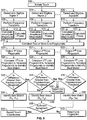
- FIG. 9 illustrates a method for determining a location of a live touch event on the touch panel 401 of FIG. 7 based on two or more acoustic fingerprints that are constructed based on two or more digitized signals.
- an operator initiates a touch event at an (X,Y) location on the touch panel 401, such as point (X2,Y2) 424.
- the A/D converter 126 detects the first, second through M signals as discussed previously and outputs first, second through M sets of digitized signals 148 to the processor module 128.
- the frequency transform module 134 performs a frequency transform on first, second though M digitized signals 148 corresponding to the first, second through M sensor signals, and outputs first, second through M frequency transform data sets.
- information may be extracted from the first, second through M frequency transform data sets based on magnitude and phase to construct two or more separate fingerprints.
- one, two, less than M, or more than M fingerprints may be constructed based on magnitude ratio and/or phase difference and that other acoustic fingerprint construction may be used.
- the amplitude magnitude module 130 calculates first, second and M sets of amplitude magnitudes based on the frequency transform data sets of 508, 509, and 510, respectively, over the frequency range.
- the processor module 128 may construct at least one live fingerprint based on magnitude ratio.
- the amplitude magnitude module 130 determines the magnitude ratio based on the amplitude magnitudes, and may combine different signals such as determining a first magnitude ratio based on the first and Mth amplitude magnitudes and a second magnitude ratio based on the second and Mth amplitude magnitudes. Therefore, any combination of signals may be used, and some signals may be utilized more than once.
- a live fingerprint based on the phase difference can be constructed by determining phases and computing a phase difference profile.
- the phase module 132 determines the phase of each of the first, second through M frequency transform data sets, and at 518 the processor module 128 may construct a live fingerprint based on the phase difference.
- the phase module 132 determines the phase difference between two or more signals, and any grouping of two or more signals may be used.
- the processor module 128 outputs first, second through Pth live fingerprints 520, 521 and 522. At 524, 525 and 526, the processor module 128 compares the corresponding first, second through Pth live fingerprint of the live touch event to the template fingerprints to determine differences there-between and to identify the first, second through Pth template fingerprints that are "best matches" with respect to the first, second through Pth live fingerprints.
- the template fingerprints may be the first, second through N template fingerprints 140, 142 and 144 within the calibration file 138, the first, second through N template fingerprints 174, 176 and 178 within the calibration file 164, or the fingerprints within an additional or other calibration file (not shown).
- the processor module 128 may determine a score(s) (which may be one of a lowest or highest score) that indicates a possible candidate position or best matching template fingerprint.
- the processor module 128 may compare the difference between the best matching template fingerprints and the live fingerprint to a predetermined threshold.
- thresholding may be accomplished for only one of the best matching template fingerprints and the live fingerprint.
- no thresholding may be used.
- the method passes to 532 and the live fingerprint is rejected.
- the method may be terminated based on a single rejection.
- the method may be terminated if more than one rejection is identified or if a predetermined percentage of live fingerprints are rejected. If the difference at 528, 529 and/or 530 is less than the predetermined threshold, at 534, 535 and 536 the processor module 128 identifies the (X,Y) coordinates of the best match(es) identified at 524, 525 and 526, respectively.
- the processor module 128 determines if there is sufficient agreement between the detected (X,Y) coordinates. For example, the processor module 128 may compare each of the coordinates to each other. If one or more coordinates are beyond a predetermined distance from the others, the processor module 128 may determine that the coordinates are erroneous and discard the particular coordinates. In another example, the processor module 128 may compute an average X and an average Y value based on all of the coordinate points. Then, the Euclidean distance may be computed between the average point and each of the individual points.
- the processor module 128 determines that a valid touch has been detected and at 540 reports a set of touch coordinates to the host computer 162.
- the set of touch coordinates may be the average coordinates for example. If the processor module 128 determines that agreement is not met, the method passes to 542 where the coordinates are rejected and no touch coordinates are reported to the host computer 162. This may be the case wherein a noisy environment causes false touches to be detected.
Landscapes
- Engineering & Computer Science (AREA)
- Physics & Mathematics (AREA)
- General Engineering & Computer Science (AREA)
- Theoretical Computer Science (AREA)
- Acoustics & Sound (AREA)
- Human Computer Interaction (AREA)
- General Physics & Mathematics (AREA)
- Position Input By Displaying (AREA)
- Image Input (AREA)
- Collating Specific Patterns (AREA)
- Electronic Switches (AREA)
- User Interface Of Digital Computer (AREA)
Claims (5)
- Verfahren zum Erfassen eines Berührungsereignisses auf einem auf einem akustischen Fingerabdruck basierenden Berührungssystem, umfassend:Digitalisieren (231, 232, 502, 504, 506) erster Signale von mindestens einem ersten Sensor zum Ausbilden eines ersten Satzes digitalisierter Signale und zweiter Signale von mindestens einem zweiten Sensor zum Ausbilden eines zweiten Satzes digitalisierter Signale, wobei der mindestens erste und zweite Sensor (106, 108, 110, 112) einem Touchpanel (102) zugeordnet sind;Durchführen (233, 234, 508, 509, 510) einer Frequenztransformation an dem ersten Satz digitalisierter Signale und dem zweiten Satz digitalisierter Signale zum Ausbilden eines ersten bzw. eines zweiten frequenztransformierten Datensatzes von Frequenzkomponenten;Erstellen (241, 242, 518) eines ersten Live-Fingerabdrucks, der einen Berührungsort angibt, und eines zweiten Live-Fingerabdrucks, der einen Berührungsort angibt, für eine Berührung; undIdentifizieren des Ortes der Berührung auf Basis des ersten und des zweiten Live-Fingerabdrucks, wobei das Identifizieren ein Vergleichen (243, 244, 524, 525, 526) eines jeden des mindestens ersten und zweiten Live-Fingerabdrucks mit einer Vielzahl von Musterfingerabdrücken (140-144, 174-178) umfasst, wobei jeder der Musterfingerabdrücke Koordinaten auf dem Touchpanel (102) zugeordnet ist,wobei das Identifizieren ferner ein Identifizieren (243, 244, 524, 525, 526) eines am besten passenden Musterfingerabdrucks in Zuordnung zu jeweils dem mindestens ersten und zweiten Live-Fingerabdruck auf Basis des Vergleichs zum Liefern des Orts der Berührung umfasst,dadurch gekennzeichnet, dass der erst Live-Fingerabdruck auf Basis eines Größenverhältnisses erstellt wird, das ein Verhältnis zwischen den Amplitudengrößen des ersten frequenztransformierten Datensatzes und des zweiten frequenztransformierten Datensatzes umfasst, und der zweite Live-Fingerabdruck auf Basis einer Phasendifferenz erstellt wird, die eine Differenz zwischen dem ersten frequenztransformierten Datensatz und dem zweiten frequenztransformierten Datensatz zugeordneten Phaseninformationen umfasst, sodass der erste und der zweite Live-Fingerabdruck jeweils maßinvariant sind.
- Verfahren gemäß Anspruch 1, wobei das Identifizieren ferner umfasst:Bestimmen (252, 538) eines Abstands zwischen den Koordinaten, die den jeweils am besten passenden Live-Fingerabdrücken zugeordnet sind; undIdentifizieren (256, 540) des Orts der Berührung auf Basis der den jeweils am besten passenden Live-Fingerabdrücken zugeordneten Koordinaten, wenn der Abstand entweder a) kleiner als ein vorbestimmter Schwellenwert oder b) größer als ein vorbestimmter Schwellenwert ist.
- Auf einem akustischen Fingerabdruck basierendes Berührungssystem (400), umfassend:ein Touchpanel (401);mindestens zwei Sensoren (404, 406, 408), die mit dem Touchpanel verbunden sind, wobei die mindestens zwei Sensoren mindestens zwei Signale beschaffen, die dem Touchpanel zugeordnet sind, wobei die mindestens zwei Sensoren einen ersten Sensor, der ein erstes Signal beschafft, und einen zweiten Sensor umfassen, der ein zweites Signal beschafft, wobei die mindestens zwei Signale das erste und zweite Signal beinhalten; undein Prozessormodul zum Durchführen (233, 234, 508, 509, 510) von Frequenztransformationen auf Basis des ersten Signals zum Erzeugen eines ersten frequenztransformierten Signals und auf Basis des zweiten Signals zum Erzeugen eines zweiten frequenztransformierten Signals,wobei das Prozessormodul dazu konfiguriert ist, für ein Berührungsereignis auf Basis der frequenztransformierten Signale mindestens einen ersten und einen zweiten Live-Fingerabdruck zu erstellen (241, 242, 518), wobei jeder Live-Fingerabdruck einen Berührungsort angibt, wobei das Prozessormodul auf Basis des mindestens ersten und zweiten Live-Fingerabdrucks durch Vergleichen (243, 244, 524, 525, 526) eines jeden des mindestens ersten und zweiten Live-Fingerabdrucks mit einer Vielzahl von Musterfingerabdrücken (140-144, 174-178), Koordinaten bestimmt, die dem Berührungsereignis auf dem Touchpanel zugeordnet sind, wobei jeder der Musterfingerabdrücke Koordinaten auf dem Touchpanel (102) zugeordnet ist,wobei das Prozessormodul einen am besten passenden Musterfingerabdruck in Zuordnung zu jeweils dem mindestens ersten und zweiten Live-Fingerabdruck auf Basis des Vergleichs zum Liefern des Orts der Berührung identifiziert (243, 244, 524, 525, 526), unddadurch gekennzeichnet, dass der erst Live-Fingerabdruck auf Basis eines Größenverhältnisses erstellt wird, das ein Verhältnis zwischen den Amplitudengrößen des ersten frequenztransformierten Datensatzes und des zweiten frequenztransformierten Datensatzes umfasst, und der zweite Live-Fingerabdruck auf einer Phasendifferenz basiert, die eine Differenz zwischen dem ersten frequenztransformierten Datensatz und dem zweiten frequenztransformierten Datensatz zugeordneten Phaseninformationen umfasst, sodass der erste und der zweite Live-Fingerabdruck jeweils maßinvariant sind.
- Berührungssystem gemäß Anspruch 3, ferner umfassend einen Speicher (136), in dem mindestens eine Kalibrierungsdatei (138, 164) gespeichert ist, in der die Vielzahl von Musterfingerabdrücken (140-144, 174-178) enthalten ist, wobei das Prozessormodul auf Basis einer Durchschnittskoordinate, den Koordinatenort bestimmt, der dem Berührungsereignis zugeordnet ist, wobei die Durchschnittskoordinate auf den Koordinaten basiert, die dem jeweils am besten passenden Musterfingerabdruck zugeordnet ist.
- Berührungssystem gemäß Anspruch 3, wobei der mindestens erste und zweite Live-Fingerabdruck P Live-Fingerabdrücke umfassen, wobei P eine ganze Zahl größer als zwei ist, wobei das System ferner einen Speicher (136) umfasst, in dem mindestens eine Kalibrierungsdatei (138, 164) gespeichert ist, in der eine Vielzahl von Musterfingerabdrücken (140-144, 174-178) enthalten ist, wobei das Prozessormodul (128) P am besten passende Musterfingerabdrücke identifiziert (524, 525, 526), die den P Live-Fingerabdrücken zugeordnet sind, wobei das Prozessormodul (128) die dem Berührungsereignis zugeordneten Koordinaten auf Basis einer Majoritätslogik bestimmt.
Applications Claiming Priority (1)
| Application Number | Priority Date | Filing Date | Title |
|---|---|---|---|
| US11/824,961 US8730213B2 (en) | 2007-07-02 | 2007-07-02 | Method and system for detecting touch events based on redundant validation |
Publications (3)
| Publication Number | Publication Date |
|---|---|
| EP2012222A2 EP2012222A2 (de) | 2009-01-07 |
| EP2012222A3 EP2012222A3 (de) | 2011-07-06 |
| EP2012222B1 true EP2012222B1 (de) | 2017-04-05 |
Family
ID=39708598
Family Applications (1)
| Application Number | Title | Priority Date | Filing Date |
|---|---|---|---|
| EP08159512.6A Active EP2012222B1 (de) | 2007-07-02 | 2008-07-02 | Verfahren und System zur Erkennung von Berührungsereignissen auf der Basis redundanter Validierungen |
Country Status (5)
| Country | Link |
|---|---|
| US (1) | US8730213B2 (de) |
| EP (1) | EP2012222B1 (de) |
| JP (1) | JP2009015854A (de) |
| CN (1) | CN101339479B (de) |
| TW (1) | TW200915156A (de) |
Families Citing this family (50)
| Publication number | Priority date | Publication date | Assignee | Title |
|---|---|---|---|---|
| US8493332B2 (en) * | 2007-06-21 | 2013-07-23 | Elo Touch Solutions, Inc. | Method and system for calibrating an acoustic touchscreen |
| US8378974B2 (en) * | 2007-07-02 | 2013-02-19 | Elo Touch Solutions, Inc. | Method and system for detecting touch events based on magnitude ratios |
| JP5287855B2 (ja) * | 2008-06-04 | 2013-09-11 | 富士通株式会社 | 情報処理装置および入力制御方法 |
| KR101496844B1 (ko) * | 2008-07-28 | 2015-02-27 | 삼성디스플레이 주식회사 | 터치 스크린 표시 장치 및 그 구동 방법 |
| GB2468275A (en) | 2009-02-16 | 2010-09-08 | New Transducers Ltd | A method of making a touch-sensitive data entry screen with haptic feedback |
| JP5554517B2 (ja) * | 2009-04-22 | 2014-07-23 | 富士通コンポーネント株式会社 | タッチパネルの位置検出方法及びタッチパネル装置 |
| EP2264575B1 (de) * | 2009-06-19 | 2017-08-09 | Elo Touch Solutions, Inc. | Verfahren zur Bestimmung der Standorte von einem oder mehr Stößen oder Berührungen auf einer Objektoberfläche mit einem oder mehr Transducern |
| KR20110015745A (ko) * | 2009-08-10 | 2011-02-17 | 삼성전자주식회사 | 휴대용 단말기에서 터치 감도 조절 방법 및 장치 |
| US9696856B2 (en) | 2009-09-29 | 2017-07-04 | Elo Touch Solutions, Inc. | Method and apparatus for detecting simultaneous touch events on a bending-wave touchscreen |
| EP2333646A1 (de) * | 2009-10-27 | 2011-06-15 | STMicroelectronics Srl | Verfahren zur Bestimmung der Position eines Kontakts auf einem Berührungsbildschirm und entsprechendes System |
| CN102214028B (zh) * | 2010-04-06 | 2014-07-16 | 晨星软件研发(深圳)有限公司 | 触控板的手势识别方法与手势识别装置 |
| US9459733B2 (en) | 2010-08-27 | 2016-10-04 | Inputdynamics Limited | Signal processing systems |
| WO2012148539A1 (en) | 2011-02-25 | 2012-11-01 | Maxim Integrated Products, Inc | Capacitive touch sense architecture |
| US9086439B2 (en) | 2011-02-25 | 2015-07-21 | Maxim Integrated Products, Inc. | Circuits, devices and methods having pipelined capacitance sensing |
| US8860432B2 (en) | 2011-02-25 | 2014-10-14 | Maxim Integrated Products, Inc. | Background noise measurement and frequency selection in touch panel sensor systems |
| US10198097B2 (en) | 2011-04-26 | 2019-02-05 | Sentons Inc. | Detecting touch input force |
| US9477350B2 (en) | 2011-04-26 | 2016-10-25 | Sentons Inc. | Method and apparatus for active ultrasonic touch devices |
| US9189109B2 (en) | 2012-07-18 | 2015-11-17 | Sentons Inc. | Detection of type of object used to provide a touch contact input |
| US9639213B2 (en) | 2011-04-26 | 2017-05-02 | Sentons Inc. | Using multiple signals to detect touch input |
| US11327599B2 (en) | 2011-04-26 | 2022-05-10 | Sentons Inc. | Identifying a contact type |
| TW201250549A (en) * | 2011-06-02 | 2012-12-16 | Uc Logic Technology Corp | Touch point positioning method for optical touch panel and optical touch panel |
| US8890823B2 (en) * | 2012-01-09 | 2014-11-18 | Motorola Mobility Llc | System and method for reducing occurrences of unintended operations in an electronic device |
| US20130050132A1 (en) * | 2011-08-26 | 2013-02-28 | Analog Devices, Inc. | Techniques for capacitive touch screen control |
| US10235004B1 (en) | 2011-11-18 | 2019-03-19 | Sentons Inc. | Touch input detector with an integrated antenna |
| US11262253B2 (en) | 2017-08-14 | 2022-03-01 | Sentons Inc. | Touch input detection using a piezoresistive sensor |
| US10248262B2 (en) | 2011-11-18 | 2019-04-02 | Sentons Inc. | User interface interaction using touch input force |
| CN104169847B (zh) | 2011-11-18 | 2019-03-12 | 森顿斯公司 | 局部触觉反馈 |
| US9524063B2 (en) | 2012-07-18 | 2016-12-20 | Sentons Inc. | Detection of a number of touch contacts of a multi-touch input |
| US9078066B2 (en) | 2012-07-18 | 2015-07-07 | Sentons Inc. | Touch input surface speaker |
| US9348468B2 (en) | 2013-06-07 | 2016-05-24 | Sentons Inc. | Detecting multi-touch inputs |
| TWI579797B (zh) * | 2012-08-31 | 2017-04-21 | 禾瑞亞科技股份有限公司 | 影像分割的處理器 |
| US8805865B2 (en) * | 2012-10-15 | 2014-08-12 | Juked, Inc. | Efficient matching of data |
| KR102100968B1 (ko) * | 2013-04-12 | 2020-04-16 | 삼성디스플레이 주식회사 | 모바일 장치 및 이의 구동 방법 |
| US9588552B2 (en) | 2013-09-11 | 2017-03-07 | Sentons Inc. | Attaching electrical components using non-conductive adhesive |
| US9459715B1 (en) | 2013-09-20 | 2016-10-04 | Sentons Inc. | Using spectral control in detecting touch input |
| US9880671B2 (en) | 2013-10-08 | 2018-01-30 | Sentons Inc. | Damping vibrational wave reflections |
| WO2015167511A2 (en) * | 2014-04-30 | 2015-11-05 | Empire Technology Development Llc | Adjusting tap position on touch screen |
| US10048811B2 (en) | 2015-09-18 | 2018-08-14 | Sentons Inc. | Detecting touch input provided by signal transmitting stylus |
| US10151608B2 (en) * | 2015-12-22 | 2018-12-11 | Microchip Technology Incorporated | System and method for reducing noise in a sensor system |
| US10908741B2 (en) | 2016-11-10 | 2021-02-02 | Sentons Inc. | Touch input detection along device sidewall |
| US10296144B2 (en) | 2016-12-12 | 2019-05-21 | Sentons Inc. | Touch input detection with shared receivers |
| CN108268156A (zh) * | 2016-12-30 | 2018-07-10 | 南昌欧菲生物识别技术有限公司 | 具有指纹识别功能的触摸屏及电子装置 |
| US10126877B1 (en) | 2017-02-01 | 2018-11-13 | Sentons Inc. | Update of reference data for touch input detection |
| US10585522B2 (en) * | 2017-02-27 | 2020-03-10 | Sentons Inc. | Detection of non-touch inputs using a signature |
| US11380452B2 (en) * | 2017-03-07 | 2022-07-05 | Ge-Hitachi Nuclear Energy Americas Llc | Systems and methods for position verification for inspection and repairs |
| US10530770B2 (en) * | 2017-06-28 | 2020-01-07 | International Business Machines Corporation | Pressure-based authentication |
| US11580829B2 (en) | 2017-08-14 | 2023-02-14 | Sentons Inc. | Dynamic feedback for haptics |
| EP3444708A1 (de) * | 2017-08-17 | 2019-02-20 | LNT Automation GmbH | Berührungsempfindliche fläche |
| CN107656656B (zh) * | 2017-10-24 | 2021-05-18 | 业成科技(成都)有限公司 | 声波式触控装置及其触控判断方法 |
| US20200233558A1 (en) * | 2019-01-22 | 2020-07-23 | Novatek Microelectronics Corp. | Fingerprint and touch sensor and related signal processing method |
Family Cites Families (32)
| Publication number | Priority date | Publication date | Assignee | Title |
|---|---|---|---|---|
| US3134099A (en) * | 1962-12-21 | 1964-05-19 | Ibm | Ultrasonic data converter |
| US5162618A (en) * | 1990-11-16 | 1992-11-10 | Exzec, Inc. | Acoustic touch position sensor with first order lamb wave reflective arrays |
| JPH10177448A (ja) * | 1996-12-17 | 1998-06-30 | Purimo:Kk | 入力装置及びデータ処理システム |
| FR2787608B1 (fr) | 1998-12-22 | 2001-03-30 | Clic Choc Multimedia | Plaque acoustique interactive a moyens de traitement du signal perfectionnes |
| GB9928682D0 (en) | 1999-12-06 | 2000-02-02 | Electrotextiles Comp Ltd | Input apparatus and a method of generating control signals |
| US6525717B1 (en) * | 1999-12-17 | 2003-02-25 | International Business Machines Corporation | Input device that analyzes acoustical signatures |
| US7157649B2 (en) * | 1999-12-23 | 2007-01-02 | New Transducers Limited | Contact sensitive device |
| US6456952B1 (en) * | 2000-03-29 | 2002-09-24 | Ncr Coporation | System and method for touch screen environmental calibration |
| FR2811107B1 (fr) * | 2000-06-29 | 2002-10-18 | Jean Pierre Nikolovski | Plaque acoustique interactive de precision |
| US6809726B2 (en) * | 2000-12-11 | 2004-10-26 | Xerox Corporation | Touchscreen display calibration using results history |
| JP2002215315A (ja) * | 2001-01-22 | 2002-08-02 | Kobayashi:Kk | ボード面上の座標値を入力する装置、および同入力方法 |
| US7184989B2 (en) * | 2001-03-31 | 2007-02-27 | First Data Corporation | Staged transactions systems and methods |
| GB0116310D0 (en) | 2001-07-04 | 2001-08-29 | New Transducers Ltd | Contact sensitive device |
| GB2385125A (en) | 2002-02-06 | 2003-08-13 | Soundtouch Ltd | Using vibrations generated by movement along a surface to determine position |
| US7411581B2 (en) * | 2002-02-06 | 2008-08-12 | Soundtouch Limited | Touch pad |
| US7643015B2 (en) * | 2002-05-24 | 2010-01-05 | Massachusetts Institute Of Technology | Systems and methods for tracking impacts |
| FR2841022B1 (fr) * | 2002-06-12 | 2004-08-27 | Centre Nat Rech Scient | Procede pour localiser un impact sur une surface et dispositif pour la mise en oeuvre de ce procede |
| US6871149B2 (en) * | 2002-12-06 | 2005-03-22 | New Transducers Limited | Contact sensitive device |
| GB0228512D0 (en) | 2002-12-06 | 2003-01-15 | New Transducers Ltd | Contact sensitive device |
| US7315300B2 (en) * | 2003-12-31 | 2008-01-01 | 3M Innovative Properties Company | Touch sensitive device employing impulse reconstruction |
| FR2874274B1 (fr) | 2004-08-11 | 2007-07-20 | Sensitive Object | Procede pour localiser un impact sur une surface et dispositif pour la mise en oeuvre de ce procede |
| CN101095097B (zh) | 2004-12-29 | 2012-01-25 | 传感器公司 | 确定冲击位置的方法及装置 |
| US7583808B2 (en) * | 2005-03-28 | 2009-09-01 | Mitsubishi Electric Research Laboratories, Inc. | Locating and tracking acoustic sources with microphone arrays |
| CA2604548C (en) | 2005-04-13 | 2011-08-30 | Sensitive Object | Method for determining the location of impacts by acoustic imaging |
| US20060232558A1 (en) | 2005-04-15 | 2006-10-19 | Huan-Wen Chien | Virtual keyboard |
| US7683890B2 (en) * | 2005-04-28 | 2010-03-23 | 3M Innovative Properties Company | Touch location determination using bending mode sensors and multiple detection techniques |
| US20060262104A1 (en) * | 2005-05-19 | 2006-11-23 | Sullivan Darius M | Systems and methods for distinguishing contact-induced plate vibrations from acoustic noise-induced plate vibrations |
| US8013846B2 (en) * | 2006-02-10 | 2011-09-06 | Tpk Holding Co., Ltd. | Touch detection |
| US20080180399A1 (en) * | 2007-01-31 | 2008-07-31 | Tung Wan Cheng | Flexible Multi-touch Screen |
| WO2008146098A1 (en) | 2007-05-28 | 2008-12-04 | Sensitive Object | Method for determining the position of an excitation on a surface and device for implementing such a method |
| US8493332B2 (en) * | 2007-06-21 | 2013-07-23 | Elo Touch Solutions, Inc. | Method and system for calibrating an acoustic touchscreen |
| US8378974B2 (en) * | 2007-07-02 | 2013-02-19 | Elo Touch Solutions, Inc. | Method and system for detecting touch events based on magnitude ratios |
-
2007
- 2007-07-02 US US11/824,961 patent/US8730213B2/en active Active
-
2008
- 2008-06-30 TW TW097124535A patent/TW200915156A/zh unknown
- 2008-07-02 JP JP2008173059A patent/JP2009015854A/ja active Pending
- 2008-07-02 CN CN200810214726XA patent/CN101339479B/zh not_active Expired - Fee Related
- 2008-07-02 EP EP08159512.6A patent/EP2012222B1/de active Active
Non-Patent Citations (1)
| Title |
|---|
| None * |
Also Published As
| Publication number | Publication date |
|---|---|
| EP2012222A3 (de) | 2011-07-06 |
| CN101339479B (zh) | 2013-09-25 |
| JP2009015854A (ja) | 2009-01-22 |
| EP2012222A2 (de) | 2009-01-07 |
| TW200915156A (en) | 2009-04-01 |
| CN101339479A (zh) | 2009-01-07 |
| US8730213B2 (en) | 2014-05-20 |
| US20090009488A1 (en) | 2009-01-08 |
Similar Documents
| Publication | Publication Date | Title |
|---|---|---|
| EP2012222B1 (de) | Verfahren und System zur Erkennung von Berührungsereignissen auf der Basis redundanter Validierungen | |
| US8378974B2 (en) | Method and system for detecting touch events based on magnitude ratios | |
| JP7320379B2 (ja) | 圧力信号処理 | |
| US8232977B2 (en) | System and method for detection with a digitizer sensor | |
| EP2483763B1 (de) | Verfahren und vorrichtung zur detektion von simultanen berührungen eines akustischen touchscreens | |
| CN110132458B (zh) | 一种动态或准动态力度检测装置及方法 | |
| US10095350B2 (en) | Processing device and processing method | |
| US5751276A (en) | Method for calibrating touch panel displays | |
| JP6660066B2 (ja) | 周波数分割変調タッチシステムにおける信号検知 | |
| US20160070413A1 (en) | Method and System for Resolving Multiple Proximate Touches | |
| CN103109252A (zh) | 使用声学超声阻抗描记术的用于指向装置的方法和系统 | |
| US20120249471A1 (en) | Method of identifying a multi-touch rotation gesture and device using the same | |
| US9684407B2 (en) | Method and apparatus for determining shape and orientation of a touch object on handheld devices | |
| EP3980877B1 (de) | Berührungsempfindliches gerät und verfahren | |
| CN107688771B (zh) | 一种半导体器件 | |
| CN104345956A (zh) | 防止手掌误触的方法 | |
| US11003294B1 (en) | Techniques for using a touch screen to perform ear detection using emulated self capacitance sensing | |
| TW202127204A (zh) | 偵測觸控面板半浸入導電液體的液面線的觸控處理裝置、觸控系統與其方法 | |
| US12197675B2 (en) | Touch-sensitive apparatus and method | |
| TWI724727B (zh) | 用於觸控面板半浸入導電液體時的觸控處理裝置、觸控系統與其方法 | |
| TWI724726B (zh) | 偵測觸控面板半浸入導電液體的液面線的觸控處理裝置、觸控系統與其方法 |
Legal Events
| Date | Code | Title | Description |
|---|---|---|---|
| PUAI | Public reference made under article 153(3) epc to a published international application that has entered the european phase |
Free format text: ORIGINAL CODE: 0009012 |
|
| AK | Designated contracting states |
Kind code of ref document: A2 Designated state(s): AT BE BG CH CY CZ DE DK EE ES FI FR GB GR HR HU IE IS IT LI LT LU LV MC MT NL NO PL PT RO SE SI SK TR |
|
| AX | Request for extension of the european patent |
Extension state: AL BA MK RS |
|
| PUAL | Search report despatched |
Free format text: ORIGINAL CODE: 0009013 |
|
| AK | Designated contracting states |
Kind code of ref document: A3 Designated state(s): AT BE BG CH CY CZ DE DK EE ES FI FR GB GR HR HU IE IS IT LI LT LU LV MC MT NL NO PL PT RO SE SI SK TR |
|
| AX | Request for extension of the european patent |
Extension state: AL BA MK RS |
|
| 17P | Request for examination filed |
Effective date: 20111129 |
|
| AKX | Designation fees paid |
Designated state(s): DE FR GB |
|
| RAP1 | Party data changed (applicant data changed or rights of an application transferred) |
Owner name: ELO TOUCH SOLUTIONS, INC. |
|
| 17Q | First examination report despatched |
Effective date: 20141216 |
|
| GRAP | Despatch of communication of intention to grant a patent |
Free format text: ORIGINAL CODE: EPIDOSNIGR1 |
|
| INTG | Intention to grant announced |
Effective date: 20161026 |
|
| GRAS | Grant fee paid |
Free format text: ORIGINAL CODE: EPIDOSNIGR3 |
|
| GRAA | (expected) grant |
Free format text: ORIGINAL CODE: 0009210 |
|
| AK | Designated contracting states |
Kind code of ref document: B1 Designated state(s): DE FR GB |
|
| REG | Reference to a national code |
Ref country code: GB Ref legal event code: FG4D |
|
| REG | Reference to a national code |
Ref country code: DE Ref legal event code: R096 Ref document number: 602008049563 Country of ref document: DE |
|
| REG | Reference to a national code |
Ref country code: DE Ref legal event code: R097 Ref document number: 602008049563 Country of ref document: DE |
|
| PLBE | No opposition filed within time limit |
Free format text: ORIGINAL CODE: 0009261 |
|
| STAA | Information on the status of an ep patent application or granted ep patent |
Free format text: STATUS: NO OPPOSITION FILED WITHIN TIME LIMIT |
|
| 26N | No opposition filed |
Effective date: 20180108 |
|
| GBPC | Gb: european patent ceased through non-payment of renewal fee |
Effective date: 20170705 |
|
| REG | Reference to a national code |
Ref country code: FR Ref legal event code: ST Effective date: 20180330 |
|
| PG25 | Lapsed in a contracting state [announced via postgrant information from national office to epo] |
Ref country code: GB Free format text: LAPSE BECAUSE OF NON-PAYMENT OF DUE FEES Effective date: 20170705 |
|
| PG25 | Lapsed in a contracting state [announced via postgrant information from national office to epo] |
Ref country code: FR Free format text: LAPSE BECAUSE OF NON-PAYMENT OF DUE FEES Effective date: 20170731 |
|
| P01 | Opt-out of the competence of the unified patent court (upc) registered |
Effective date: 20230520 |
|
| PGFP | Annual fee paid to national office [announced via postgrant information from national office to epo] |
Ref country code: DE Payment date: 20250728 Year of fee payment: 18 |