EP2011970A2 - Reinforced airfoils - Google Patents
Reinforced airfoils Download PDFInfo
- Publication number
- EP2011970A2 EP2011970A2 EP08251175A EP08251175A EP2011970A2 EP 2011970 A2 EP2011970 A2 EP 2011970A2 EP 08251175 A EP08251175 A EP 08251175A EP 08251175 A EP08251175 A EP 08251175A EP 2011970 A2 EP2011970 A2 EP 2011970A2
- Authority
- EP
- European Patent Office
- Prior art keywords
- airfoil
- walls
- longitudinal ribs
- interior space
- cross beams
- Prior art date
- Legal status (The legal status is an assumption and is not a legal conclusion. Google has not performed a legal analysis and makes no representation as to the accuracy of the status listed.)
- Granted
Links
Images





Classifications
-
- F—MECHANICAL ENGINEERING; LIGHTING; HEATING; WEAPONS; BLASTING
- F01—MACHINES OR ENGINES IN GENERAL; ENGINE PLANTS IN GENERAL; STEAM ENGINES
- F01D—NON-POSITIVE DISPLACEMENT MACHINES OR ENGINES, e.g. STEAM TURBINES
- F01D9/00—Stators
- F01D9/02—Nozzles; Nozzle boxes; Stator blades; Guide conduits, e.g. individual nozzles
-
- F—MECHANICAL ENGINEERING; LIGHTING; HEATING; WEAPONS; BLASTING
- F01—MACHINES OR ENGINES IN GENERAL; ENGINE PLANTS IN GENERAL; STEAM ENGINES
- F01D—NON-POSITIVE DISPLACEMENT MACHINES OR ENGINES, e.g. STEAM TURBINES
- F01D5/00—Blades; Blade-carrying members; Heating, heat-insulating, cooling or antivibration means on the blades or the members
- F01D5/12—Blades
- F01D5/14—Form or construction
- F01D5/147—Construction, i.e. structural features, e.g. of weight-saving hollow blades
-
- F—MECHANICAL ENGINEERING; LIGHTING; HEATING; WEAPONS; BLASTING
- F01—MACHINES OR ENGINES IN GENERAL; ENGINE PLANTS IN GENERAL; STEAM ENGINES
- F01D—NON-POSITIVE DISPLACEMENT MACHINES OR ENGINES, e.g. STEAM TURBINES
- F01D5/00—Blades; Blade-carrying members; Heating, heat-insulating, cooling or antivibration means on the blades or the members
- F01D5/12—Blades
- F01D5/14—Form or construction
- F01D5/18—Hollow blades, i.e. blades with cooling or heating channels or cavities; Heating, heat-insulating or cooling means on blades
- F01D5/187—Convection cooling
- F01D5/188—Convection cooling with an insert in the blade cavity to guide the cooling fluid, e.g. forming a separation wall
-
- F—MECHANICAL ENGINEERING; LIGHTING; HEATING; WEAPONS; BLASTING
- F01—MACHINES OR ENGINES IN GENERAL; ENGINE PLANTS IN GENERAL; STEAM ENGINES
- F01D—NON-POSITIVE DISPLACEMENT MACHINES OR ENGINES, e.g. STEAM TURBINES
- F01D5/00—Blades; Blade-carrying members; Heating, heat-insulating, cooling or antivibration means on the blades or the members
- F01D5/12—Blades
- F01D5/14—Form or construction
- F01D5/18—Hollow blades, i.e. blades with cooling or heating channels or cavities; Heating, heat-insulating or cooling means on blades
- F01D5/187—Convection cooling
- F01D5/188—Convection cooling with an insert in the blade cavity to guide the cooling fluid, e.g. forming a separation wall
- F01D5/189—Convection cooling with an insert in the blade cavity to guide the cooling fluid, e.g. forming a separation wall the insert having a tubular cross-section, e.g. airfoil shape
-
- F—MECHANICAL ENGINEERING; LIGHTING; HEATING; WEAPONS; BLASTING
- F05—INDEXING SCHEMES RELATING TO ENGINES OR PUMPS IN VARIOUS SUBCLASSES OF CLASSES F01-F04
- F05D—INDEXING SCHEME FOR ASPECTS RELATING TO NON-POSITIVE-DISPLACEMENT MACHINES OR ENGINES, GAS-TURBINES OR JET-PROPULSION PLANTS
- F05D2240/00—Components
- F05D2240/10—Stators
- F05D2240/12—Fluid guiding means, e.g. vanes
- F05D2240/126—Baffles or ribs
-
- F—MECHANICAL ENGINEERING; LIGHTING; HEATING; WEAPONS; BLASTING
- F05—INDEXING SCHEMES RELATING TO ENGINES OR PUMPS IN VARIOUS SUBCLASSES OF CLASSES F01-F04
- F05D—INDEXING SCHEME FOR ASPECTS RELATING TO NON-POSITIVE-DISPLACEMENT MACHINES OR ENGINES, GAS-TURBINES OR JET-PROPULSION PLANTS
- F05D2260/00—Function
- F05D2260/20—Heat transfer, e.g. cooling
- F05D2260/201—Heat transfer, e.g. cooling by impingement of a fluid
Definitions
- the present disclosure generally relates to airfoils.
- engine stators include a plurality of stationary or variable vanes having an airfoil shape.
- such airfoils can experience airfoil bulge, a condition in which the opposed walls of the airfoil expand outward into the engine gas path due to the high temperatures in which the airfoils are used and/or the pressure difference between the interior and the exterior of the airfoils.
- Such bulge deforms the airfoils so as to temporarily or permanently alter their aerodynamic properties, which can significantly reduce the aerodynamic efficiency of the engine.
- airfoil bulge can lead to airfoil rupture, which can cause substantial damage to the engine.
- auxiliary longitudinal ribs within the airfoil that extend along the length of the airfoil and connect the opposed walls of the airfoil.
- additional ribs are effective in reducing airfoil bulge, such a solution increases the number of internal surfaces of the airfoil and therefore the difficulty in cooling the airfoil.
- the additional use of ribs can increase the difficulty in providing baffles within the airfoils that control the flow of cooling air through the airfoils.
- the addition of ribs can significantly increase the weight of the airfoils, and therefore the engine in which they are used.
- a reinforced airfoil comprises an airfoil body including opposed walls defining a hollow interior space, and a reinforcement member provided on at least one of the walls within the interior space, the reinforcement member increasing the thickness of the at least one wall so as to resist deformation of the at least one wall but not extending from one wall to the other.
- airfoil bulge can have detrimental effects on the operation and condition of a turbine engine.
- auxiliary longitudinal ribs can reduce airfoil bulge, the use of such ribs creates difficulties in relation to airfoil cooling and can undesirably increase the weight of the airfoils and the engines in which they are used.
- airfoil bulge can be reduced or avoided without use of longitudinal ribs through use of reinforcement members that are provided on the inner surfaces of the airfoil walls.
- FIG. 1 illustrates an embodiment of a reinforced airfoil 10 in perspective view.
- the airfoil 10 comprises a stator vane used in a turbine engine.
- the airfoil 10 comprises a turbine blade.
- the airfoil 10 generally comprises an airfoil body 12 that comprises opposed first and second walls 14 and 16.
- the first wall 14 is a pressure-side wall having a concave shape and the second wall 16 is a suction-side wall having a convex shape.
- the walls 14, 16 connect together at opposed edges to form a leading edge 18 and a trailing edge 20 of the airfoil 10.
- the walls 14, 16 are generally elongated and terminate in at least one platform that is used to mount the airfoil 10 to a component of a turbine engine.
- an inner diameter platform 22 and an outer diameter platform 24 are provided.
- first and second walls 14, 16 define a core that forms a hollow interior space 26 through which cooling air can flow.
- first and second longitudinal ribs 28 and 30 are provided within the interior space 26 that extend between and connect the first and second walls 14, 16 to provide structural integrity to the airfoil 10.
- the longitudinal ribs 28, 30 divide the interior space 26 of the airfoil 10 into three different longitudinal hollow compartments, including a first or front compartment 32, a second or middle compartment 34, and a third or rear compartment 36.
- a plurality of reinforcement members 38 that reduce or prevent the walls 14, 16 of the airfoil 10 from bulging outward into the gas path of the engine in which the airfoil is used.
- the reinforcement members 38 extend to and connect the longitudinal ribs 28, 30.
- the reinforcement members 38 are arranged in a vertical (in the orientation of FIG. 1 ) row that extends within the interior space 26 along a length of the body 12.
- reinforcement members 38 are only shown on the wall 16 in the view of FIG. 1 , similar reinforcement members can be provided on wall 14.
- the airfoil 10 is composed of a metal material (e.g., alloy) and is formed using a casting process. In other embodiments, the airfoil 10 is composed of a ceramic material and is formed using a casting process. In still other embodiments, the airfoil 10 is composed of a composite material and is formed using an injection molding process.
- a metal material e.g., alloy
- the airfoil 10 is composed of a ceramic material and is formed using a casting process.
- the airfoil 10 is composed of a composite material and is formed using an injection molding process.
- FIG. 2 illustrates a single reinforcement member 38 provided on one of the walls (i.e., wall 16) of the airfoil 10.
- the reinforcement member 38 takes the form of an X-shaped girder formed on the wall 16 that extends between the longitudinal ribs 28, 30 (only rib 30 visible in FIG. 2 ).
- the reinforcement member 42 is defined by a generally circular central portion 40 from which extend multiple elongated arms cross braces or beams 42 that extend in a transverse direction across an inner surface.
- four cross beams 42 are provided, with two cross beams extending to each longitudinal rib 28, 30 ( FIG. 1 ).
- the central portion 40 is positioned on the wall 16 approximately halfway between the longitudinal ribs 28, 30 ( FIG. 1 ) and the cross beams 42 are approximately equal in length.
- the central portion 40 and the cross beams 42 provide increased thickness (i.e., cross-section) to the wall 16 at discrete areas that resists deformation of the wall so as to reduce or avoid bulge.
- Optimal dimensions for the central portion 40 and the cross beams depend upon the particular application and can, for example, 42 be mathematically determined through finite element analysis.
- the reinforcement members 38 do not comprise components that extend between and connect the walls 14, 16 of the airfoil 10. Instead, the reinforcement members 38 comprise discrete members that extend inwardly from the inner surfaces of the walls 14, 16 only a finite distance to a limited degree to increase the thickness, and therefore strength, of the walls.
- the reinforcement members 38 are formed with the airfoil walls during the formation of the airfoil such that the reinforcement members and the walls on which the reinforcement members are provided are unitarily formed the same continuous piece of material. Such construction is contrasted with the addition of the reinforcement members 38 to the walls of the airfoil after the walls have already been formed. In some embodiments, the reinforcement members 38 are directly cast or injection molded with the airfoil walls.
- the central portion 40 is provided to avoid the provision of sharp corners that could cause and/or propagate cracks at the location at which the cross beams meet.
- the reinforcement member 38 further forms no sharp corners with the airfoil wall or its longitudinal ribs. Instead, fillets (i.e., rounded corners) 44 are provided at the interfaces between the central portion 40 and the airfoil wall 16, between the central portion and the arms 42, and between the arms and both the airfoil walls and the longitudinal ribs 28, 30.
- rounded corners 46 are provided at the top edges of each of the central portion 40 and the cross beams 42.
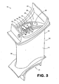
- FIGs. 3 and 4 illustrate the airfoil 10 of FIG. 1 with a baffle 50 provided within the interior space 26.
- the baffle 50 is provided within the middle compartment 34 of the interior space 26 between the longitudinal ribs 28, 30 ( FIG. 4 ).
- the baffle 50 comprises an elongated, hollow member having a rectangular cross-section that is defined by lateral walls 52 and end walls 54.
- the lateral walls 52 comprise a plurality of openings 56 that are used to direct cooling air toward the inner surfaces of the airfoil walls 14, 16.
- the baffle 50 includes at least one end flange 58 that contacts the ends of one or more of the walls 14, 16 and the longitudinal ribs 28,30.
- FIG. 5 is a partial perspective view of another reinforced airfoil 60 that illustrates an alternative reinforcement member 62.
- the reinforcement member 62 is similar to the reinforcement member 38 shown in FIG. 2 . Therefore, as indicated in FIG. 5 , the reinforcement member 62 takes the form of an X-shaped girder formed on an airfoil wall 64 that extends between longitudinal ribs of the airfoil 60 (only rib 66 visible in FIG. 5 ).
- an X-shape is illustrated in FIG. 5 and described herein, it is to be understood that alternative shapes can be used.
- the reinforcement members 62 can comprise a Y-shape, T-shape, I-shape or any other shape or configuration that provides the desired degree of reinforcement.
- the reinforcement member 62 shown in FIG. 5 includes a generally circular central portion 68 from which extend multiple elongated cross braces or beams 70.
- the reinforcement member 62 includes a stand-off 72 that extends from the central portion 68.
- the stand-off 72 comprises an elongated protrusion that extends away from the airfoil wall 64.
- the stand-off 72 comprises a generally planar baffle engagement surface 74 that is bifurcated by a groove or slot 76 that extends downward along the length of the stand-off toward the airfoil wall 64.
- the stand-off 72 acts as a spacer that maintains a desired spacing between a baffle and the airfoil wall 64 on which the reinforcement member 62 is provided.
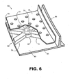
- a baffle 78 is provided that abuts the baffle engagement surface 74 such that a desired amount of spacing, S, is maintained between the baffle and the inner surface 80 of the wall 64. Due to the provision of the slot 76, the cross-sectional area of the stand-off 72 is reduced so as to reduce impedance of the flow of cooling air through the airfoil 60. It is noted that a stand-off need not be provided in the center of the reinforcement member 62.
- one of more stand-offs may, in addition or in exception, extend from one or more of the cross beams 70.
- any reinforcement member 62 may comprise a plurality of stand-offs instead of just one as illustrated in FIGs. 5 and 6 . It is further noted that stand-offs are not required in all embodiments. For instance, stand-offs may be omitted in cases in which compartmentalization of the interior space 26 is desired.
- FIG. 7 is a partial perspective view of another reinforced airfoil 84 that illustrates an alternative reinforcement member 86.
- the reinforcement member 86 is also similar to the reinforcement member 38 shown in FIG. 2 and therefore also takes the form of an X-shaped girder formed on an airfoil wall 88 that extends between longitudinal ribs of the airfoil 84 (only rib 90 visible in FIG. 5 ).
- the reinforcement member 86 includes a generally circular central portion 92 from which extend multiple elongated cross braces or beams 94.
- the reinforcement member 86 includes a baffle stand-off 96 that extends from the central portion 92.
- the stand-off 96 comprises a generally frustoconical member that includes a planar baffle engagement surface 98.
- the stand-off 96 acts as a spacer that maintains a desired spacing between a baffle and the airfoil wall 88 on which the reinforcement member 86 is provided. Due to the frustoconical shape of the stand-off 96, the cross-sectional area of the stand-off is reduced so as to reduce impedance of the flow of cooling ai,r through the airfoil 84.
Landscapes
- Engineering & Computer Science (AREA)
- Mechanical Engineering (AREA)
- General Engineering & Computer Science (AREA)
- Architecture (AREA)
- Turbine Rotor Nozzle Sealing (AREA)
Abstract
Description
- The present disclosure generally relates to airfoils.
- Multiple airfoils are typically used within turbine engines. For example, engine stators include a plurality of stationary or variable vanes having an airfoil shape.
- During use in engines, such airfoils can experience airfoil bulge, a condition in which the opposed walls of the airfoil expand outward into the engine gas path due to the high temperatures in which the airfoils are used and/or the pressure difference between the interior and the exterior of the airfoils. Such bulge deforms the airfoils so as to temporarily or permanently alter their aerodynamic properties, which can significantly reduce the aerodynamic efficiency of the engine. In extreme cases, airfoil bulge can lead to airfoil rupture, which can cause substantial damage to the engine.
- Prior solutions to airfoil bulge have included the provision of auxiliary longitudinal ribs within the airfoil that extend along the length of the airfoil and connect the opposed walls of the airfoil. Although such additional ribs are effective in reducing airfoil bulge, such a solution increases the number of internal surfaces of the airfoil and therefore the difficulty in cooling the airfoil. In addition, the additional use of ribs can increase the difficulty in providing baffles within the airfoils that control the flow of cooling air through the airfoils. Furthermore, the addition of ribs can significantly increase the weight of the airfoils, and therefore the engine in which they are used.
- In one embodiment, a reinforced airfoil comprises an airfoil body including opposed walls defining a hollow interior space, and a reinforcement member provided on at least one of the walls within the interior space, the reinforcement member increasing the thickness of the at least one wall so as to resist deformation of the at least one wall but not extending from one wall to the other.
- The disclosed airfoils can be better understood with reference to the following drawings. The components in the drawings are not necessarily to scale.
-
FIG. 1 is a cutaway perspective view an embodiment of a reinforced airfoil. -
FIG. 2 is a partial perspective view of the airfoil ofFIG. 1 , illustrating a reinforcement member of the airfoil. -
FIG. 3 is a perspective view of the airfoil ofFIG. 1 with a baffle provided within the interior of the airfoil. -
FIG. 4 is a further cutaway perspective view of the airfoil ofFIG. 1 , illustrating the positioning of the baffle shown inFIG. 3 , which is also shown in cutaway view. -
FIG. 5 is a partial perspective view of another reinforced airfoil, illustrating an alternative reinforcement member. -
FIG. 6 is a partial perspective view of the reinforced airfoil ofFIG. 5 in use with a baffle. -
FIG. 7 is a partial perspective view of a further reinforced airfoil, illustrating a further alternative reinforcement member. - As described in the foregoing, airfoil bulge can have detrimental effects on the operation and condition of a turbine engine. Although the use of auxiliary longitudinal ribs can reduce airfoil bulge, the use of such ribs creates difficulties in relation to airfoil cooling and can undesirably increase the weight of the airfoils and the engines in which they are used. As described in the following, however, airfoil bulge can be reduced or avoided without use of longitudinal ribs through use of reinforcement members that are provided on the inner surfaces of the airfoil walls.
- Described in the following are reinforced airfoils. Although specific embodiments are presented, those embodiments are mere example implementations and it is noted that other embodiments are possible. All such embodiments are intended to fall within the scope of this disclosure.
- Turning to the figures, in which like numerals identify corresponding components,
FIG. 1 illustrates an embodiment of areinforced airfoil 10 in perspective view. In some embodiments, theairfoil 10 comprises a stator vane used in a turbine engine. In other embodiments, theairfoil 10 comprises a turbine blade. As indicated inFIG. 1 , theairfoil 10 generally comprises anairfoil body 12 that comprises opposed first andsecond walls first wall 14 is a pressure-side wall having a concave shape and thesecond wall 16 is a suction-side wall having a convex shape. Thewalls edge 18 and atrailing edge 20 of theairfoil 10. Thewalls airfoil 10 to a component of a turbine engine. In the embodiment ofFIG. 1 , aninner diameter platform 22 and anouter diameter platform 24 are provided. - As is further indicated in
FIG. 1 , the first andsecond walls interior space 26 through which cooling air can flow. In the embodiment ofFIG. 1 , first and secondlongitudinal ribs interior space 26 that extend between and connect the first andsecond walls airfoil 10. Thelongitudinal ribs interior space 26 of theairfoil 10 into three different longitudinal hollow compartments, including a first orfront compartment 32, a second ormiddle compartment 34, and a third orrear compartment 36. Provided within themiddle compartment 34 is a plurality ofreinforcement members 38 that reduce or prevent thewalls airfoil 10 from bulging outward into the gas path of the engine in which the airfoil is used. As indicated inFIG. 4 , thereinforcement members 38 extend to and connect thelongitudinal ribs FIG. 1 , thereinforcement members 38 are arranged in a vertical (in the orientation ofFIG. 1 ) row that extends within theinterior space 26 along a length of thebody 12. Notably, althoughreinforcement members 38 are only shown on thewall 16 in the view ofFIG. 1 , similar reinforcement members can be provided onwall 14. - In some embodiments, the
airfoil 10 is composed of a metal material (e.g., alloy) and is formed using a casting process. In other embodiments, theairfoil 10 is composed of a ceramic material and is formed using a casting process. In still other embodiments, theairfoil 10 is composed of a composite material and is formed using an injection molding process. -
FIG. 2 illustrates asingle reinforcement member 38 provided on one of the walls (i.e., wall 16) of theairfoil 10. In the embodiment ofFIG. 2 , thereinforcement member 38 takes the form of an X-shaped girder formed on thewall 16 that extends between thelongitudinal ribs 28, 30 (onlyrib 30 visible inFIG. 2 ). Thereinforcement member 42 is defined by a generally circularcentral portion 40 from which extend multiple elongated arms cross braces orbeams 42 that extend in a transverse direction across an inner surface. In the illustrated embodiment, fourcross beams 42 are provided, with two cross beams extending to eachlongitudinal rib 28, 30 (FIG. 1 ). In some embodiments, thecentral portion 40 is positioned on thewall 16 approximately halfway between thelongitudinal ribs 28, 30 (FIG. 1 ) and thecross beams 42 are approximately equal in length. - Irrespective of their particular shape and configuration, the
central portion 40 and thecross beams 42 provide increased thickness (i.e., cross-section) to thewall 16 at discrete areas that resists deformation of the wall so as to reduce or avoid bulge. Optimal dimensions for thecentral portion 40 and the cross beams depend upon the particular application and can, for example, 42 be mathematically determined through finite element analysis. - From the above it can be appreciated that the
reinforcement members 38 do not comprise components that extend between and connect thewalls airfoil 10. Instead, thereinforcement members 38 comprise discrete members that extend inwardly from the inner surfaces of thewalls - In some embodiments, the
reinforcement members 38 are formed with the airfoil walls during the formation of the airfoil such that the reinforcement members and the walls on which the reinforcement members are provided are unitarily formed the same continuous piece of material. Such construction is contrasted with the addition of thereinforcement members 38 to the walls of the airfoil after the walls have already been formed. In some embodiments, thereinforcement members 38 are directly cast or injection molded with the airfoil walls. - The
central portion 40 is provided to avoid the provision of sharp corners that could cause and/or propagate cracks at the location at which the cross beams meet. As is apparent fromFIG. 2 , thereinforcement member 38 further forms no sharp corners with the airfoil wall or its longitudinal ribs. Instead, fillets (i.e., rounded corners) 44 are provided at the interfaces between thecentral portion 40 and theairfoil wall 16, between the central portion and thearms 42, and between the arms and both the airfoil walls and thelongitudinal ribs rounded corners 46 are provided at the top edges of each of thecentral portion 40 and thecross beams 42. -
FIGs. 3 and4 illustrate theairfoil 10 ofFIG. 1 with abaffle 50 provided within theinterior space 26. Notably, the provision of such abaffle 50 is made possible by the absence of auxiliary longitudinal ribs that could be positioned between thelongitudinal ribs baffle 50 is provided within themiddle compartment 34 of theinterior space 26 between thelongitudinal ribs 28, 30 (FIG. 4 ). Thebaffle 50 comprises an elongated, hollow member having a rectangular cross-section that is defined bylateral walls 52 and endwalls 54. In the embodiment ofFIGs. 3 and4 , thelateral walls 52 comprise a plurality ofopenings 56 that are used to direct cooling air toward the inner surfaces of theairfoil walls FIGs. 3 and4 , thebaffle 50 includes at least oneend flange 58 that contacts the ends of one or more of thewalls longitudinal ribs -
FIG. 5 is a partial perspective view of another reinforcedairfoil 60 that illustrates analternative reinforcement member 62. Thereinforcement member 62 is similar to thereinforcement member 38 shown inFIG. 2 . Therefore, as indicated inFIG. 5 , thereinforcement member 62 takes the form of an X-shaped girder formed on anairfoil wall 64 that extends between longitudinal ribs of the airfoil 60 (onlyrib 66 visible inFIG. 5 ). Although an X-shape is illustrated inFIG. 5 and described herein, it is to be understood that alternative shapes can be used. For instance, thereinforcement members 62 can comprise a Y-shape, T-shape, I-shape or any other shape or configuration that provides the desired degree of reinforcement. Thereinforcement member 62 shown inFIG. 5 includes a generally circularcentral portion 68 from which extend multiple elongated cross braces or beams 70. In the embodiment ofFIG. 5 , however, thereinforcement member 62 includes a stand-off 72 that extends from thecentral portion 68. As indicated inFIG. 5 , the stand-off 72 comprises an elongated protrusion that extends away from theairfoil wall 64. In the embodiment ofFIG. 5 , the stand-off 72 comprises a generally planarbaffle engagement surface 74 that is bifurcated by a groove orslot 76 that extends downward along the length of the stand-off toward theairfoil wall 64. - In use, the stand-off 72 acts as a spacer that maintains a desired spacing between a baffle and the
airfoil wall 64 on which thereinforcement member 62 is provided. Such functionality is illustrated inFIG. 6 . As shown in that figure, abaffle 78 is provided that abuts thebaffle engagement surface 74 such that a desired amount of spacing, S, is maintained between the baffle and theinner surface 80 of thewall 64. Due to the provision of theslot 76, the cross-sectional area of the stand-off 72 is reduced so as to reduce impedance of the flow of cooling air through theairfoil 60. It is noted that a stand-off need not be provided in the center of thereinforcement member 62. In other embodiments, one of more stand-offs may, in addition or in exception, extend from one or more of the cross beams 70. Moreover, anyreinforcement member 62 may comprise a plurality of stand-offs instead of just one as illustrated inFIGs. 5 and6 . It is further noted that stand-offs are not required in all embodiments. For instance, stand-offs may be omitted in cases in which compartmentalization of theinterior space 26 is desired. -
FIG. 7 is a partial perspective view of another reinforcedairfoil 84 that illustrates analternative reinforcement member 86. Thereinforcement member 86 is also similar to thereinforcement member 38 shown inFIG. 2 and therefore also takes the form of an X-shaped girder formed on anairfoil wall 88 that extends between longitudinal ribs of the airfoil 84 (onlyrib 90 visible inFIG. 5 ). Thereinforcement member 86 includes a generally circularcentral portion 92 from which extend multiple elongated cross braces or beams 94. In the embodiment ofFIG. 7 , however, thereinforcement member 86 includes a baffle stand-off 96 that extends from thecentral portion 92. As indicated inFIG. 7 , the stand-off 96 comprises a generally frustoconical member that includes a planarbaffle engagement surface 98. - Like the stand-
off 72, the stand-off 96 acts as a spacer that maintains a desired spacing between a baffle and theairfoil wall 88 on which thereinforcement member 86 is provided. Due to the frustoconical shape of the stand-off 96, the cross-sectional area of the stand-off is reduced so as to reduce impedance of the flow of cooling ai,r through theairfoil 84.
Claims (18)
- A reinforced airfoil (10; 60; 84) comprising:an airfoil body including opposed walls (14, 16; 64; 88) defining a hollow interior space (26); anda reinforcement member (38; 62; 86) provided on at least one of the walls (14, 16; 64; 88) within the interior space (26), the reinforcement member (38; 62; 86) increasing the thickness of the at least one wall (14, 16; 64; 88) so as to resist deformation of the at least one wall (14, 16; 64; 88) but not extending from one wall to the other.
- The airfoil of claim 1, further comprising first and second longitudinal ribs (28, 30; 66; 90) provided within the interior space (26), each longitudinal rib extending between and connecting the walls.
- The airfoil of claim 2, wherein the reinforcement member (38; 62; 86) is provided between the longitudinal ribs (28; 30; 66; 90).
- The airfoil of claim 3, wherein the reinforcement member (38; 62; 86) extends from the first longitudinal rib (28) to the second longitudinal rib (30) and is connected to both ribs.
- The airfoil of any of claims 2 to 4, further comprising a baffle (50; 78) provided within the interior space (26) between the first and second longitudinal ribs (28, 30).
- The airfoil of claim 5, wherein the reinforcement member (62; 86) includes a baffle stand-off (72; 96) that maintains a desired degree of spacing between the baffle (50; 78) and the at least one wall (64; 88).
- The airfoil of any preceding claim, wherein the reinforcement member (38; 62; 86) includes a central portion (40; 68; 92) and cross beams (42; 70; 94) that extend from the central portion (40; 68; 92).
- The airfoil of claim 7, wherein the central portion (40; 68; 92) and the cross beams (42; 70; 94) are both connected to an inner surface of the at least one wall.
- The airfoil of claim 8, wherein the central portion (40; 68; 92) and the cross beams (42; 70; 94) form an X-shaped girder.
- A reinforced airfoil (10; 60; 84) comprising:an airfoil body including opposed first and second walls (14; 16; 64; 88), the walls defining a hollow interior space (26);first and second longitudinal ribs (28, 30; 60; 90) provided within the interior space (26), the longitudinal ribs extending between and connecting the first and second walls (14, 16; 64; 88); andmultiple reinforcement members (38; 62; 86) formed on inner surfaces of the first and second walls (14, 16; 64; 88) within the interior space (26) between the longitudinal ribs (28, 30; 66; 90), the reinforcement members including cross beams (42; 70; 94) that extend and connect to the longitudinal ribs (28, 30; 66; 90), the cross beams (42; 70; 94) increasing the thickness of the walls (14, 16; 64; 88) at discrete locations so as to resist deformation of the walls during use of the airfoil.
- The airfoil of claim 10, wherein the reinforcement members (38; 62; 86) further include a central portion (40; 68; 92) from which the cross beams (42; 70; 94) extend.
- The airfoil of claim 11, wherein the reinforcement members comprise fillets (44) at connection points between the cross beams (42) and the central portion (40).
- The airfoil of claim 11 or 12, wherein the reinforcement members comprise fillets (44) at connection points between the cross beams (42) and longitudinal ribs (28, 30).
- A reinforced airfoil (10; 60; 84) for a turbine engine, the airfoil comprising:an airfoil body including opposed first and second walls (14, 16; 64; 88), the walls defining a hollow interior space (26) and including first and second ends;at least one platform (22, 24) connected to one of the first and second ends of the first and second walls;first and second longitudinal ribs (28, 30; 66; 90) provided within the interior space (26) of the airfoil body, the longitudinal ribs (28, 30; 66; 90) extending along a length of the airfoil body and further extending between and connecting the first and second walls (14, 16; 64; 88), the longitudinal ribs defining a middle compartment (34) of the interior space (26); anda plurality of reinforcement members (38; 62; 86) unitarily formed with the first and second walls (14, 16; 64; 88) and provided on inner surfaces of the walls within the middle compartment (34), the reinforcement members (38; 62; 86) being arranged in a row on each wall that extends along the length of the airfoil body within the interior space (26), each reinforcement member (38; 62; 86) including a central portion (40; 68; 92) from which extend cross beams (42; 70; 94), wherein the cross beams (42; 70; 94) extend and connect to the longitudinal ribs (28, 30; 66; 90).
- The airfoil of claim 14, wherein the reinforcement members (38) comprise fillets (44) at connection points between the cross beams (42) and the inner surfaces of the first and second walls (14, 16) and between the cross beams (42) and longitudinal ribs (28, 30).
- The airfoil of any of claims 11 to 15, wherein the central portion (40; 68; 92) and the cross beams (42; 70; 94) form an X-shaped girder.
- The airfoil of any of claims 10 to 16, wherein the reinforcement members (62; 86) further include a baffle stand-off (72; 96) that maintains a desired degree of spacing between a baffle (50; 78) and the first and second walls (64; 88).
- The airfoil of claim 17, further comprising a baffle (50; 78) provided within the interior space (26) between the first and second longitudinal ribs (66; 90) and spaced from the first and second walls (64; 88) a desired distance through use of the baffle stand-offs (72; 96).
Applications Claiming Priority (1)
| Application Number | Priority Date | Filing Date | Title |
|---|---|---|---|
| US11/774,151 US7857588B2 (en) | 2007-07-06 | 2007-07-06 | Reinforced airfoils |
Publications (3)
| Publication Number | Publication Date |
|---|---|
| EP2011970A2 true EP2011970A2 (en) | 2009-01-07 |
| EP2011970A3 EP2011970A3 (en) | 2012-03-21 |
| EP2011970B1 EP2011970B1 (en) | 2014-02-12 |
Family
ID=39415304
Family Applications (1)
| Application Number | Title | Priority Date | Filing Date |
|---|---|---|---|
| EP08251175.9A Active EP2011970B1 (en) | 2007-07-06 | 2008-03-28 | Reinforced airfoils |
Country Status (2)
| Country | Link |
|---|---|
| US (1) | US7857588B2 (en) |
| EP (1) | EP2011970B1 (en) |
Cited By (10)
| Publication number | Priority date | Publication date | Assignee | Title |
|---|---|---|---|---|
| EP2233694A1 (en) * | 2009-03-26 | 2010-09-29 | United Technologies Corporation | Metering standoffs for airfoil baffle |
| EP2471612A1 (en) * | 2010-12-30 | 2012-07-04 | United Technologies Corporation | Method and casting core for forming a landing for welding a baffle inserted into an airfoil |
| CN103277145A (en) * | 2013-06-09 | 2013-09-04 | 哈尔滨工业大学 | Cooling blade of gas turbine |
| CN104727857A (en) * | 2013-12-20 | 2015-06-24 | 阿尔斯通技术有限公司 | Rotor blade and guide vane airfoil for a gas turbine engine |
| EP2929955A1 (en) * | 2014-04-07 | 2015-10-14 | United Technologies Corporation | Rib bumper system |
| EP3020924A1 (en) * | 2014-11-12 | 2016-05-18 | United Technologies Corporation | A gas turbine component comprising a lattice cooling structure |
| EP3179042A1 (en) * | 2015-12-07 | 2017-06-14 | United Technologies Corporation | Gas turbine engine component having engineered vascular structure |
| GB2556142A (en) * | 2016-08-24 | 2018-05-23 | Rolls Royce Plc | A dual walled component for a gas turbine engine |
| EP3335873A1 (en) * | 2016-11-17 | 2018-06-20 | United Technologies Corporation | Article having ceramic wall with flow turbulators |
| US10774653B2 (en) | 2018-12-11 | 2020-09-15 | Raytheon Technologies Corporation | Composite gas turbine engine component with lattice structure |
Families Citing this family (32)
| Publication number | Priority date | Publication date | Assignee | Title |
|---|---|---|---|---|
| US8123167B2 (en) * | 2008-12-15 | 2012-02-28 | Embraer S.A. | Impact resistant aircraft leading edge structures and aircraft including the same |
| US8713909B2 (en) | 2009-03-04 | 2014-05-06 | United Technologies Corporation | Elimination of unfavorable outflow margin |
| US8342797B2 (en) * | 2009-08-31 | 2013-01-01 | Rolls-Royce North American Technologies Inc. | Cooled gas turbine engine airflow member |
| US9133819B2 (en) | 2011-07-18 | 2015-09-15 | Kohana Technologies Inc. | Turbine blades and systems with forward blowing slots |
| US9091175B2 (en) | 2011-08-24 | 2015-07-28 | Pratt & Whitney Canada Corp. | Hollow core airfoil stiffener rib |
| US9175570B2 (en) | 2012-04-24 | 2015-11-03 | United Technologies Corporation | Airfoil including member connected by articulated joint |
| US9121286B2 (en) * | 2012-04-24 | 2015-09-01 | United Technologies Corporation | Airfoil having tapered buttress |
| US9296039B2 (en) | 2012-04-24 | 2016-03-29 | United Technologies Corporation | Gas turbine engine airfoil impingement cooling |
| US9470095B2 (en) | 2012-04-24 | 2016-10-18 | United Technologies Corporation | Airfoil having internal lattice network |
| US9133712B2 (en) | 2012-04-24 | 2015-09-15 | United Technologies Corporation | Blade having porous, abradable element |
| US9249668B2 (en) | 2012-04-24 | 2016-02-02 | United Technologies Corporation | Airfoil with break-way, free-floating damper member |
| US9267380B2 (en) | 2012-04-24 | 2016-02-23 | United Technologies Corporation | Airfoil including loose damper |
| US9404369B2 (en) * | 2012-04-24 | 2016-08-02 | United Technologies Corporation | Airfoil having minimum distance ribs |
| US9074482B2 (en) * | 2012-04-24 | 2015-07-07 | United Technologies Corporation | Airfoil support method and apparatus |
| US9243502B2 (en) | 2012-04-24 | 2016-01-26 | United Technologies Corporation | Airfoil cooling enhancement and method of making the same |
| US9273566B2 (en) | 2012-06-22 | 2016-03-01 | United Technologies Corporation | Turbine engine variable area vane |
| US9103222B2 (en) | 2012-06-22 | 2015-08-11 | United Technologies Corporation | Turbine engine variable area vane with feather seal |
| US10605086B2 (en) | 2012-11-20 | 2020-03-31 | Honeywell International Inc. | Turbine engines with ceramic vanes and methods for manufacturing the same |
| US10215048B2 (en) | 2013-01-21 | 2019-02-26 | United Technologies Corporation | Variable area vane arrangement for a turbine engine |
| EP2956257B1 (en) | 2013-02-12 | 2022-07-13 | Raytheon Technologies Corporation | Gas turbine engine component cooling passage and space eating core |
| EP2971532A4 (en) | 2013-03-15 | 2016-11-16 | United Technologies Corp | ADDITIVE MANUFACTURE OF CHICANES, COATINGS AND MATRIXES |
| US9896950B2 (en) * | 2013-09-09 | 2018-02-20 | Rolls-Royce Deutschland Ltd & Co Kg | Turbine guide wheel |
| EP3047111B1 (en) | 2013-09-18 | 2020-05-06 | United Technologies Corporation | Component for a gas turbine engine, corresponding gas turbine engine and method of cooling |
| US10087776B2 (en) * | 2015-09-08 | 2018-10-02 | General Electric Company | Article and method of forming an article |
| US10253986B2 (en) * | 2015-09-08 | 2019-04-09 | General Electric Company | Article and method of forming an article |
| US10465526B2 (en) | 2016-11-15 | 2019-11-05 | Rolls-Royce Corporation | Dual-wall airfoil with leading edge cooling slot |
| US10648341B2 (en) | 2016-11-15 | 2020-05-12 | Rolls-Royce Corporation | Airfoil leading edge impingement cooling |
| US10844724B2 (en) * | 2017-06-26 | 2020-11-24 | General Electric Company | Additively manufactured hollow body component with interior curved supports |
| US10370983B2 (en) * | 2017-07-28 | 2019-08-06 | Rolls-Royce Corporation | Endwall cooling system |
| US10450873B2 (en) * | 2017-07-31 | 2019-10-22 | Rolls-Royce Corporation | Airfoil edge cooling channels |
| US11459899B2 (en) | 2018-03-23 | 2022-10-04 | Raytheon Technologies Corporation | Turbine component with a thin interior partition |
| US11377964B2 (en) * | 2018-11-09 | 2022-07-05 | Raytheon Technologies Corporation | Airfoil with cooling passage network having arced leading edge |
Family Cites Families (23)
| Publication number | Priority date | Publication date | Assignee | Title |
|---|---|---|---|---|
| US2458975A (en) * | 1943-12-09 | 1949-01-11 | Curtiss Wright Corp | Rib reinforcing means for propeller blades |
| DE1776015A1 (en) * | 1968-09-04 | 1971-09-16 | Daimler Benz Ag | Turbine blade |
| BE755567A (en) * | 1969-12-01 | 1971-02-15 | Gen Electric | FIXED VANE STRUCTURE, FOR GAS TURBINE ENGINE AND ASSOCIATED TEMPERATURE ADJUSTMENT ARRANGEMENT |
| US4257734A (en) * | 1978-03-22 | 1981-03-24 | Rolls-Royce Limited | Guide vanes for gas turbine engines |
| US5383766A (en) * | 1990-07-09 | 1995-01-24 | United Technologies Corporation | Cooled vane |
| US5253824A (en) * | 1991-04-16 | 1993-10-19 | General Electric Company | Hollow core airfoil |
| US5695321A (en) * | 1991-12-17 | 1997-12-09 | General Electric Company | Turbine blade having variable configuration turbulators |
| US5232344A (en) * | 1992-01-17 | 1993-08-03 | United Technologies Corporation | Internally damped blades |
| US5509783A (en) * | 1993-02-09 | 1996-04-23 | Preci-Spark, Ltd. | Reinforced vane |
| JPH08135402A (en) * | 1994-11-11 | 1996-05-28 | Mitsubishi Heavy Ind Ltd | Gas turbine stationary blade structure |
| US5873699A (en) * | 1996-06-27 | 1999-02-23 | United Technologies Corporation | Discontinuously reinforced aluminum gas turbine guide vane |
| DE19713268B4 (en) * | 1997-03-29 | 2006-01-19 | Alstom | Chilled gas turbine blade |
| US6048174A (en) * | 1997-09-10 | 2000-04-11 | United Technologies Corporation | Impact resistant hollow airfoils |
| EP0945595A3 (en) * | 1998-03-26 | 2001-10-10 | Mitsubishi Heavy Industries, Ltd. | Gas turbine cooled blade |
| EP1173657B1 (en) * | 1999-03-09 | 2003-08-20 | Siemens Aktiengesellschaft | Turbine blade and method for producing a turbine blade |
| GB2350867B (en) * | 1999-06-09 | 2003-03-19 | Rolls Royce Plc | Gas turbine airfoil internal air system |
| CN100376766C (en) * | 2000-03-22 | 2008-03-26 | 西门子公司 | Turbine blade reinforcing and cooling structure |
| EP1136651A1 (en) * | 2000-03-22 | 2001-09-26 | Siemens Aktiengesellschaft | Cooling system for an airfoil |
| RU2271454C2 (en) * | 2000-12-28 | 2006-03-10 | Альстом Текнолоджи Лтд | Making of platforms in straight-flow axial gas turbine with improved cooling of wall sections and method of decreasing losses through clearances |
| DE10301755A1 (en) * | 2003-01-18 | 2004-07-29 | Rolls-Royce Deutschland Ltd & Co Kg | Fan blade for a gas turbine engine |
| FR2858650B1 (en) * | 2003-08-06 | 2007-05-18 | Snecma Moteurs | AUBE ROTOR HOLLOW FOR THE TURBINE OF A GAS TURBINE ENGINE |
| US7001150B2 (en) * | 2003-10-16 | 2006-02-21 | Pratt & Whitney Canada Corp. | Hollow turbine blade stiffening |
| US7216694B2 (en) * | 2004-01-23 | 2007-05-15 | United Technologies Corporation | Apparatus and method for reducing operating stress in a turbine blade and the like |
-
2007
- 2007-07-06 US US11/774,151 patent/US7857588B2/en active Active
-
2008
- 2008-03-28 EP EP08251175.9A patent/EP2011970B1/en active Active
Cited By (27)
| Publication number | Priority date | Publication date | Assignee | Title |
|---|---|---|---|---|
| US8109724B2 (en) | 2009-03-26 | 2012-02-07 | United Technologies Corporation | Recessed metering standoffs for airfoil baffle |
| US8480366B2 (en) | 2009-03-26 | 2013-07-09 | United Technologies Corporation | Recessed metering standoffs for airfoil baffle |
| EP2233694A1 (en) * | 2009-03-26 | 2010-09-29 | United Technologies Corporation | Metering standoffs for airfoil baffle |
| US9403208B2 (en) | 2010-12-30 | 2016-08-02 | United Technologies Corporation | Method and casting core for forming a landing for welding a baffle inserted in an airfoil |
| EP2471612A1 (en) * | 2010-12-30 | 2012-07-04 | United Technologies Corporation | Method and casting core for forming a landing for welding a baffle inserted into an airfoil |
| US11707779B2 (en) | 2010-12-30 | 2023-07-25 | Raytheon Technologies Corporation | Method and casting core for forming a landing for welding a baffle inserted in an airfoil |
| US11077494B2 (en) | 2010-12-30 | 2021-08-03 | Raytheon Technologies Corporation | Method and casting core for forming a landing for welding a baffle inserted in an airfoil |
| EP2471612B1 (en) * | 2010-12-30 | 2019-07-10 | United Technologies Corporation | Method and casting core for forming a landing for welding a baffle inserted into an airfoil |
| CN103277145A (en) * | 2013-06-09 | 2013-09-04 | 哈尔滨工业大学 | Cooling blade of gas turbine |
| US9903209B2 (en) | 2013-12-20 | 2018-02-27 | Ansaldo Energia Switzerland AG | Rotor blade and guide vane airfoil for a gas turbine engine |
| CN104727857A (en) * | 2013-12-20 | 2015-06-24 | 阿尔斯通技术有限公司 | Rotor blade and guide vane airfoil for a gas turbine engine |
| EP2886797A1 (en) * | 2013-12-20 | 2015-06-24 | Alstom Technology Ltd | A hollow cooled gas turbine rotor blade or guide vane, wherein the cooling cavities comprise pins interconnected with ribs |
| US10099275B2 (en) | 2014-04-07 | 2018-10-16 | United Technologies Corporation | Rib bumper system |
| US11148190B2 (en) | 2014-04-07 | 2021-10-19 | Raytheon Technologies Corporation | Rib bumper system |
| EP3064291A1 (en) * | 2014-04-07 | 2016-09-07 | United Technologies Corporation | Rib bumper system |
| EP2929955A1 (en) * | 2014-04-07 | 2015-10-14 | United Technologies Corporation | Rib bumper system |
| US9982544B2 (en) | 2014-11-12 | 2018-05-29 | United Technologies Corporation | Cooling having tailored flow resistance |
| EP3020924A1 (en) * | 2014-11-12 | 2016-05-18 | United Technologies Corporation | A gas turbine component comprising a lattice cooling structure |
| EP3179042A1 (en) * | 2015-12-07 | 2017-06-14 | United Technologies Corporation | Gas turbine engine component having engineered vascular structure |
| GB2556142B (en) * | 2016-08-24 | 2019-11-27 | Rolls Royce Plc | A Dual Walled Aerofoil for a Gas Turbine Engine |
| US10612395B2 (en) | 2016-08-24 | 2020-04-07 | Rolls-Royce Plc | Dual walled component for a gas turbine engine |
| GB2556142A (en) * | 2016-08-24 | 2018-05-23 | Rolls Royce Plc | A dual walled component for a gas turbine engine |
| EP3335873A1 (en) * | 2016-11-17 | 2018-06-20 | United Technologies Corporation | Article having ceramic wall with flow turbulators |
| US10436062B2 (en) | 2016-11-17 | 2019-10-08 | United Technologies Corporation | Article having ceramic wall with flow turbulators |
| US11333036B2 (en) | 2016-11-17 | 2022-05-17 | Raytheon Technologies | Article having ceramic wall with flow turbulators |
| US10774653B2 (en) | 2018-12-11 | 2020-09-15 | Raytheon Technologies Corporation | Composite gas turbine engine component with lattice structure |
| US11168568B2 (en) | 2018-12-11 | 2021-11-09 | Raytheon Technologies Corporation | Composite gas turbine engine component with lattice |
Also Published As
| Publication number | Publication date |
|---|---|
| EP2011970A3 (en) | 2012-03-21 |
| US7857588B2 (en) | 2010-12-28 |
| EP2011970B1 (en) | 2014-02-12 |
| US20090010765A1 (en) | 2009-01-08 |
Similar Documents
| Publication | Publication Date | Title |
|---|---|---|
| EP2011970B1 (en) | Reinforced airfoils | |
| US5295789A (en) | Turbomachine flow-straightener blade | |
| EP2592228B1 (en) | Turbine blade and engine component | |
| JP7130753B2 (en) | Gas turbine blade and manufacturing method thereof | |
| US9279331B2 (en) | Gas turbine engine airfoil with dirt purge feature and core for making same | |
| EP1467065B1 (en) | Turbine blade | |
| JP5977884B2 (en) | Asymmetrical trailing edge cooling hole | |
| US7118325B2 (en) | Cooling passageway turn | |
| US9546552B2 (en) | Gas turbine | |
| EP2650477B1 (en) | Thin-walled reinforcement lattice structure for hollow CMC buckets | |
| CZ20021393A3 (en) | Cast airfoil structure with openings which do not require plugging | |
| EP2187001A1 (en) | Blade structure for turbine | |
| JP2003314201A (en) | Moving blade used in turbomachine | |
| KR20070078974A (en) | Microcircuits for Small Engines | |
| RU2646663C2 (en) | Impingement cooling of gas turbine rotor and stator blades | |
| US8602741B2 (en) | Turbine vane for a stationary gas turbine | |
| KR19990045246A (en) | Hollow airfoils for gas turbines | |
| JP2013181538A5 (en) | ||
| EP1493513B1 (en) | Turbine bucket core stabilizing device and related method | |
| US9650899B2 (en) | Impingement cooling of turbine blades or vanes | |
| CN115380153B (en) | Blades made from a variety of materials | |
| CN111335964A (en) | Engine turbine cooling blade manufactured through additive manufacturing | |
| JPH0642301A (en) | Cooling air passage sectional shape for gas turbine air-cooled moving blade | |
| KR20230027211A (en) | Turbine blade and its processing method |
Legal Events
| Date | Code | Title | Description |
|---|---|---|---|
| PUAI | Public reference made under article 153(3) epc to a published international application that has entered the european phase |
Free format text: ORIGINAL CODE: 0009012 |
|
| AK | Designated contracting states |
Kind code of ref document: A2 Designated state(s): AT BE BG CH CY CZ DE DK EE ES FI FR GB GR HR HU IE IS IT LI LT LU LV MC MT NL NO PL PT RO SE SI SK TR |
|
| AX | Request for extension of the european patent |
Extension state: AL BA MK RS |
|
| PUAL | Search report despatched |
Free format text: ORIGINAL CODE: 0009013 |
|
| AK | Designated contracting states |
Kind code of ref document: A3 Designated state(s): AT BE BG CH CY CZ DE DK EE ES FI FR GB GR HR HU IE IS IT LI LT LU LV MC MT NL NO PL PT RO SE SI SK TR |
|
| AX | Request for extension of the european patent |
Extension state: AL BA MK RS |
|
| RIC1 | Information provided on ipc code assigned before grant |
Ipc: F01D 9/02 20060101AFI20120215BHEP |
|
| 17P | Request for examination filed |
Effective date: 20120921 |
|
| AKX | Designation fees paid |
Designated state(s): DE GB |
|
| GRAP | Despatch of communication of intention to grant a patent |
Free format text: ORIGINAL CODE: EPIDOSNIGR1 |
|
| INTG | Intention to grant announced |
Effective date: 20130813 |
|
| GRAS | Grant fee paid |
Free format text: ORIGINAL CODE: EPIDOSNIGR3 |
|
| GRAA | (expected) grant |
Free format text: ORIGINAL CODE: 0009210 |
|
| AK | Designated contracting states |
Kind code of ref document: B1 Designated state(s): DE GB |
|
| REG | Reference to a national code |
Ref country code: GB Ref legal event code: FG4D |
|
| REG | Reference to a national code |
Ref country code: DE Ref legal event code: R096 Ref document number: 602008030237 Country of ref document: DE Effective date: 20140327 |
|
| REG | Reference to a national code |
Ref country code: DE Ref legal event code: R097 Ref document number: 602008030237 Country of ref document: DE |
|
| PLBE | No opposition filed within time limit |
Free format text: ORIGINAL CODE: 0009261 |
|
| STAA | Information on the status of an ep patent application or granted ep patent |
Free format text: STATUS: NO OPPOSITION FILED WITHIN TIME LIMIT |
|
| 26N | No opposition filed |
Effective date: 20141113 |
|
| REG | Reference to a national code |
Ref country code: DE Ref legal event code: R097 Ref document number: 602008030237 Country of ref document: DE Effective date: 20141113 |
|
| REG | Reference to a national code |
Ref country code: DE Ref legal event code: R082 Ref document number: 602008030237 Country of ref document: DE Representative=s name: SCHMITT-NILSON SCHRAUD WAIBEL WOHLFROM PATENTA, DE |
|
| REG | Reference to a national code |
Ref country code: DE Ref legal event code: R082 Ref document number: 602008030237 Country of ref document: DE Representative=s name: SCHMITT-NILSON SCHRAUD WAIBEL WOHLFROM PATENTA, DE Ref country code: DE Ref legal event code: R081 Ref document number: 602008030237 Country of ref document: DE Owner name: UNITED TECHNOLOGIES CORP. (N.D.GES.D. STAATES , US Free format text: FORMER OWNER: UNITED TECHNOLOGIES CORP., HARTFORD, CONN., US |
|
| REG | Reference to a national code |
Ref country code: DE Ref legal event code: R081 Ref document number: 602008030237 Country of ref document: DE Owner name: RAYTHEON TECHNOLOGIES CORPORATION (N.D.GES.D.S, US Free format text: FORMER OWNER: UNITED TECHNOLOGIES CORP. (N.D.GES.D. STAATES DELAWARE), FARMINGTON, CONN., US Ref country code: DE Ref legal event code: R081 Ref document number: 602008030237 Country of ref document: DE Owner name: RTX CORPORATION (N.D.GES.D. STAATES DELAWARE),, US Free format text: FORMER OWNER: UNITED TECHNOLOGIES CORP. (N.D.GES.D. STAATES DELAWARE), FARMINGTON, CONN., US |
|
| P01 | Opt-out of the competence of the unified patent court (upc) registered |
Effective date: 20230519 |
|
| REG | Reference to a national code |
Ref country code: DE Ref legal event code: R081 Ref document number: 602008030237 Country of ref document: DE Owner name: RTX CORPORATION (N.D.GES.D. STAATES DELAWARE),, US Free format text: FORMER OWNER: RAYTHEON TECHNOLOGIES CORPORATION (N.D.GES.D.STAATES DELAWARE), ARLINGTON, VA, US |
|
| PGFP | Annual fee paid to national office [announced via postgrant information from national office to epo] |
Ref country code: GB Payment date: 20260220 Year of fee payment: 19 |
|
| PGFP | Annual fee paid to national office [announced via postgrant information from national office to epo] |
Ref country code: DE Payment date: 20260219 Year of fee payment: 19 |