EP2011960A2 - Anordnung für Unterwasseranwendung - Google Patents
Anordnung für Unterwasseranwendung Download PDFInfo
- Publication number
- EP2011960A2 EP2011960A2 EP08012009A EP08012009A EP2011960A2 EP 2011960 A2 EP2011960 A2 EP 2011960A2 EP 08012009 A EP08012009 A EP 08012009A EP 08012009 A EP08012009 A EP 08012009A EP 2011960 A2 EP2011960 A2 EP 2011960A2
- Authority
- EP
- European Patent Office
- Prior art keywords
- arrangement
- voltage
- subsea
- cable
- switching unit
- Prior art date
- Legal status (The legal status is an assumption and is not a legal conclusion. Google has not performed a legal analysis and makes no representation as to the accuracy of the status listed.)
- Withdrawn
Links
Images

Classifications
-
- H—ELECTRICITY
- H02—GENERATION; CONVERSION OR DISTRIBUTION OF ELECTRIC POWER
- H02B—BOARDS, SUBSTATIONS OR SWITCHING ARRANGEMENTS FOR THE SUPPLY OR DISTRIBUTION OF ELECTRIC POWER
- H02B1/00—Frameworks, boards, panels, desks, casings; Details of substations or switching arrangements
- H02B1/26—Casings; Parts thereof or accessories therefor
- H02B1/28—Casings; Parts thereof or accessories therefor dustproof, splashproof, drip-proof, waterproof or flameproof
-
- H—ELECTRICITY
- H02—GENERATION; CONVERSION OR DISTRIBUTION OF ELECTRIC POWER
- H02J—ELECTRIC POWER NETWORKS; CIRCUIT ARRANGEMENTS OR SYSTEMS FOR SUPPLYING OR DISTRIBUTING ELECTRIC POWER; SYSTEMS FOR STORING ELECTRIC ENERGY
- H02J13/00—Circuit arrangements for providing remote monitoring or remote control of equipment in a power distribution network
- H02J13/13—Circuit arrangements for providing remote monitoring or remote control of equipment in a power distribution network characterised by the transmission of data to equipment in the power network
- H02J13/1317—Circuit arrangements for providing remote monitoring or remote control of equipment in a power distribution network characterised by the transmission of data to equipment in the power network using an auxiliary transmission line
-
- H—ELECTRICITY
- H02—GENERATION; CONVERSION OR DISTRIBUTION OF ELECTRIC POWER
- H02J—ELECTRIC POWER NETWORKS; CIRCUIT ARRANGEMENTS OR SYSTEMS FOR SUPPLYING OR DISTRIBUTING ELECTRIC POWER; SYSTEMS FOR STORING ELECTRIC ENERGY
- H02J4/00—Circuit arrangements for mains or distribution networks not specified as AC or DC; Circuit arrangements for mains or distribution networks combining AC and DC sections or sub-networks
Definitions
- the present invention has its general application to an arrangement and especially to an arrangement related to a subsea electric power distributing AC-system, and as such adapted for a subsea application.
- More precisely said arrangement is being enclosed in a watertight casing, adapted to withstand high underwater pressure at deep sea applications, such as up to 2000 m and above.
- Said casing is exposing a main power input connection, adapted for a watertight co-ordination with a first subsea main cable and a main power output connection, adapted for a watertight co-ordination with a second subsea main cable.
- Said second subsea cable being adapted for causing a power supply to an AC-adapted consumer, in the form of a device or an equipment, such as a pump or similar electrically powered equipment.
- the present invention has its application in subsea plants for bringing or boosting hydrocarbons from the bottom of a sea area to a topside platform or to land, for a subsequent treatment.
- Said casing is exposing a main power input connection, adapted for a watertight co-ordination with usually a very long first subsea cable, supplying the required AC-voltage and AC-current.
- first subsea cables may be, for some applications, in the range of up to 200 km and above and the power supply may be up to 200 MVA and above, which means that special criteria and application must be considered when connecting and/or disconnecting such a high load consumer, such as a device or an equipment, usually in the form of an electric AC-three phase motor or the like.
- a used 3-phase AC-motor normally is to be dimensioned for a high and predetermined start up AC-voltage and an expected high start up AC-current, by and when applying a direct starting mode.
- a main power output connection, related to said casing, is adapted for a similar watertight co-ordination with a second subsea cable, said second subsea cable being adapted for a power supply to an AC-current and AC-voltage adapted consumer, such as a device or an equipment, as illustrated above.
- an AC-voltage transformer means adapted to a fixed AC-voltage transforming ratio, to compensate for any AC-voltage drop, caused by a cable related resistance, inductance and/or capacitance.
- the electrical criteria related to the consumer's device or equipment in the form of an AC-load, is calculated and known as to its starting mode and its effect as well as the length of and other criteria related to the mentioned first subsea cable supplying the required AC-voltage
- the construction of the used arrangement based upon the length of and the other criteria related to the mentioned second subsea cable, connected to the consumer's device or equipment, as the AC-load, the AC-voltage transformer means may be set to a calculated value or ratio.
- an AC-load circuit disconnecting (breaking) or connecting means adapted for a direct disconnecting or breaking of an AC-loaded connection or adapted for a direct connecting of an AC-loaded connection, however such breaking or connecting means are complicated in construction, in order to withstand any caused arc development, when breaking and connecting large effects, especially capacitance or reactance related or exposing circuits.
- NO-load disconnecting or breaking and connecting means which is adapted to activate a breaking mode or a connecting mode at a regulated AC-voltage at 0-level and thereafter, by frequency control means connect the load to an increasing AC-voltage.
- the present invention has its use in a NO-load disconnecting or breaking mode and a connecting mode and used within a subsea application.
- control unit is adapted to cause a disconnecting or breaking sequence, in a first operative mode, to regulate the output AC-voltage via said voltage regulating means towards and to zero, or at least almost to zero, and in a subsequent second operative mode bringing the NO-load switching unit from an ON-position to an OFF-position.
- control unit at a zero AC-voltage condition, is adapted to cause a connecting sequence, in a third operative mode, to bring the NO-load switching unit from an OFF-position to an ON-position and in a subsequent fourth operative mode regulate the output voltage from said voltage regulating means from zero to a predetermined AC-voltage level.
- control unit is to be connectable to said main control system by a subsea cable, using a watertight connection, adapted for a third subsea cable.
- the present invention has its application within, is related to, and comprises of an arrangement, related to a subsea electric power distributing AC-system, and adapted for a deep subsea application, wherein said arrangement being enclosed in a watertight casing, whereby said casing is exposing a main power input connection, adapted for a watertight co-ordination with a first subsea cable, and a main power output connection, adapted for a watertight co-ordination with a second subsea cable, said second subsea cable being adapted for a power supply to an AC-adapted consumer, as a device or an equipment, such as a compressor or a pump equipment or the like.
- the present invention in particular teaches that the technique known in this manner should be supplemented, in order to, among other things, enable the formation of said arrangement include interconnected at least: a voltage regulating means, connected to said first cable, a NO-load switching unit, connected to said second cable, and a control unit, whereby said control unit is to be adapted, in a disconnecting or breaking sequence, in a first operative mode, to regulate the output voltage from or via said voltage regulating means towards and to zero, or at least almost to zero, and in a second subsequent operative mode, bringing the NO-load switching unit from an ON-position to an OFF-position.
- control unit to be adapted, in a connecting sequence and at zero AC-voltage, in a third operative mode, to bring the NO-load switching unit from an OFF-position to an ON-position and in a subsequent fourth operative mode, to regulate the output voltage from or via said voltage regulating means from zero to a predetermined AC-voltage level.
- Said voltage regulating means is to be controlled by said control unit within said casing and governed by a main control system.
- Said control unit is further to be connected to a main control system by a third sub-sea cable, using a watertight connection, adapted for said subsea cable.
- each of or a selected number of said branches is/are allotted a voltage regulating means and a NO-load switching unit for individually bringing each of said or predetermined branches to an OFF-mode or to an ON-mode or vice versa.
- Said voltage regulating means is adapted to regulate and to reduce the output voltage or power towards zero by a magnetic flux adoption.
- Said voltage regulating means is based upon a semi conductive technology, one or more positive temperature coefficient resistors, and/or mechanically or electrically controlled inductors.
- Said NO-load switching unit is based upon a mechanical disconnection or breaking and/or a connection, being operable in a subsea environment and within an oil filled casing.
- Said NO-load switching unit is based on a subsea wet mate power connector, hydraulically or electrically operable elements, which are adapted to operate by related elements, such as sliding elements.
- Said NO-load switching unit is based upon an arrangement and/or a device for causing a physical separation of its contact means.
- Said voltage regulating means and said NO-load switching unit is adapted to and/or sensible for a frequency transmission, say down to 0 Hz, and to a top high frequency transmission, say up to 1000 Hz.
- the present invention especially includes interconnected at least: a voltage regulating means, connected to said first cable, and a NO-load switching unit, connected to said second cable and a control unit, enclosed in said casing.
- Said control unit is adapted, in a disconnecting or breaking operative mode related to a power supply to a consumer, in a first operative mode, to regulate the output voltage from or via said voltage regulating means towards zero, and/or at least almost to zero, and in a second subsequent operative mode bringing the NO-load switching unit from an ON-position to an OFF-position, or a vice versa function, for connecting the power supply to the consumer.
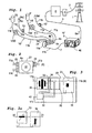
- Figure 1 is an over all view of a typical large subsea electrical power distribution system, where a land related grid 1, via a cable network 2, is feeding a switching means 3.
- Said switching means 3 is connected to a transformer 4, which via a subsea cable, an umbilical, 5, adapted for an AC-voltage and AC-current, is connected to a main transformer unit or means 6.
- control information carrying cable intended to transmit information to and from control circuits 40, enclosed in and/or related to said unit 6.
- Said main transformer unit or means 6 includes a main transformer connection chamber with bushing and penetrator, such as three one phase penetrators and termination assemblies.
- This main transformer means 6 is, via a schematically illustrated subsea cable 7, connected to a switchgear arrangement 8.
- Such a subsea switchgear arrangement 8 comprising switches, is adapted to expose a complete and flexible module, arranged on a support structure, with connection points for umbilical/power cable and is adapted for control of electrical power supply and protection of other power equipment in case of abnormal conditions.
- Said switches within said switchgear arrangement 8 can operate at full load and has "fail-safe open".
- switchgear arrangements 8 includes four switching means 8a - 8d, each dimensioned for 24kV/500A and connected through a MECON 36kV/500A.
- Said four switching means 8a, 8b, 8c and 8d are connected to different effect consuming apparatuses 9, 9a; 9', 9a', which here are activated, deactivated and/or driven by a "Subsea Variable Speed Drive” (denoted VSD-drive), having the reference numerals 10a, 10; 10a', 10'.
- a "Subsea Variable Speed Drive” deactivated and/or driven by a "Subsea Variable Speed Drive” (denoted VSD-drive), having the reference numerals 10a, 10; 10a', 10'.
- One switching means 8a is via a cable 11b connected to a VSD-drive 10a and further to the consumer 9, in the form of a compressor via a cable 11 b'.
- Said switching means 8b is via a cable 11c connected to a VSD-drive 10 and further to the consumer 9a, in the form of a pump, via a cable 11 d.
- Said switching means 8c is via a cable 11e connected to a VSD-drive 10a' and further to the consumer 9', in the form of a compressor, via a cable 11f.
- Said switching means 8d is via a cable 11g connected to a VSD-drive 10' and further to the consumer 9a', in the form of a pump, via a cable 11 h.
- Any used switching means 8a - 8d or coupling device being of one out of two embodiments, a first embodiment where AC-current and AC-voltages are switched ON and OFF at a zero voltage level and a second embodiment where AC-current and AC-voltages are switched ON and OFF at full power, with a present AC-voltage and AC-current, and thus causing a very high starting AC-current and an AC-voltage drop.
- the first embodiment is designated, in the following description, as a NO-load switching unit and the second embodiment is here designated, in the following description, as a power ON-load switching unit or as a FULL-load switching unit and/or VSD-drive.
- the present invention is merely related to a NO-load switching unit, and such a unit is adapted, after an ON position operative setting or mode, to raise the power output and the AC-voltage, through and by an AC-current and/or AC-voltage frequency ' control.
- Such a NO-load switching unit is adapted, before its OFF position setting or mode, to reduce the power output, through and via an AC-current and/or AC-voltage frequency control, which will be described more in detail with reference to Figure 4 .
- Figure 2 is a side elevation view of a coupling device or an arrangement 22, enclosed in a watertight casing 21, said arrangement 22, including and enclosing the circuits of and the interrelation of the circuits, forming the functions of the arrangement 22 of the present invention.
- Said casing 21 is also adapted to enclose one or more switching means 8a - 8d.
- Said second subsea cable 11 b being adapted for a power supply to an AC-current and AC-voltage adapted device 9, such as a compressor unit (9) or a pump equipment (9a).
- Said watertight casing 21 also exposes a power and/or information supplying and receiving subsea cable 11 k and a cable connection 25.
- This subsea cable 11 k is adapted for an information exchange and is transferring signals between a control unit 32 and a control circuit 40. Said cable 11k may be enclosed in or build in the cable 7 or may be a separate cable.
- said arrangement 22 includes interconnected at least: a voltage regulating means 30, connected to said first cable 11 a, a NO-load switching unit 31, connected to said second cable 11b, and said control unit 32.
- Said control unit 32 is adapted, for a disconnecting or breaking sequence, in a first operative mode, to regulate the output voltage from said voltage regulating means 30 towards and to zero, or at least almost to zero, and in a second subsequent operative mode, to bring the NO-load switching unit 31 from an ON-position to an OFF-position.
- Said control unit 32 is adapted, for a connecting sequence, to reduce the AC-voltage towards zero and, in a third operative mode, to bring the NO-load switching unit 31 from an OFF-position to an ON-position and in a fourth subsequent position or operative mode to regulate the output voltage from said voltage regulating means 30 from zero to a predetermined AC-voltage level.
- Said voltage regulating means 30 is controlled by said control unit 32 within said casing 21 and governed by a main control circuit or system 40, via said third cable 11k, using a watertight connection 25, adapted for said third subsea cable.
- each of or a selected number of said branches may be allotted a voltage regulating means 30 and a NO-load switching unit 31, for individually bringing each of said or predetermined branches to an OFF-mode and/or to an ON-mode.
- Said voltage regulating means 30 is based upon a semi conductive technology, one or more positive temperature coefficient resistors, and/or one or more mechanically or electrical controlled inductors.
- Said NO-load switching unit 31 is based upon a mechanical connection and/or disconnection, being operable within said watertight and oil filled casing 21, adapted for a subsea environment.
- Said NO-load switching unit 31 may be based on a subsea wet mate power connector, hydraulically or electrically operable elements, which are adapted to operate with sliding elements.
- Said NO-load switching unit 31 is based upon an arrangement causing a physically separate contact means.
- Said voltage regulating means 30 and said NO-load switching unit 31 are adapted to and/or sensible to a low frequency transmission, say down to 0 Hz, and to a top high frequency transmission, say up to 1000 Hz.
- a voltage regulating means 30 in the form of a subsea transformer, with controllable transfer functions, such as using a variable magnetic flux control, for regulating the output AC-voltage to magnetic flux control units 33 and/or 34.
- Said means 30 may firstly be connected to a first variable flux control 33, for an adapted variation of a series impedance, and secondly connected to a second variable flux control 34, for adapting the output AC-voltage to a selected phase/waveform, controlled and sensed in a unit 35.
- control and activating connections or connectors are arranged for said regulating means 30, said first flux control means 33, said second flux control means 34, said phase/waveform controlled unit 35, and finally said switching unit 31, by said control unit 32, for controlling the steps and processing steps that are to be performed.
- Figure 4 is showing an AC-voltage to time diagram indicating a variable input AC-voltage 41 and its variation in time.
- Figure 4 is intended to illustrate, in an AC-voltage to time diagram or graph, a NO-load connecting sequence, where a regulated AC-voltage is, at a zero level connected to a consumer, such as a pump equipment.
- This chosen sequence starts at a time moment where said control unit 32 receives, (at time sequence t1) an information carrying signal from said control circuit or equipment 40 that a selected consumer 9 is to be connected, via its switching unit 31, to the AC-voltage, however at an AC-voltage value at zero level.
- control unit 32 to activate the AC-voltage regulating means 30, connected to said first cable 11a, to reduce from the AC-voltage value 41 its output AC-voltage towards and to a zero-value, as illustrated by the AC-voltage drop 42, reaching said zero value, at the time moment t2.
- the control unit 32 has stored values to set the first and the second magnetic flux control units 33, 34, and said phase/waveform controlled unit 35 to fixed predetermined values representing the criteria of the actual consumers 9.
- said switching unit 31 is activated, by a control signal from the control unit 32, to shift from an OFF position to an ON position, without any AC-voltage over the contacts of said switching unit 31.
- said control unit 32 is activating the AC-voltage regulating means 30 to increase and to raise the output AC-voltage level 43 towards a predetermined AC-voltage value 44, at time moment t5, said AC-voltage value 44, corresponds to a value related to the selected consumer 9 considering any AC-drop expected between the switching unit 31 and the consumer 9.
- FIG. 5 is showing, in a block diagram, a control unit 32 and its related means, circuits and functions.
- One such means is adapted for the AC-voltage regulating means or unit 30, and has been allotted reference numeral 30a
- one another such means is adapted for a first magnetic flux regulating means or unit 33, and has been allotted reference numeral 33a
- one still another such means is adapted for a second magnetic flux regulating means or unit 34, and has been allotted reference numeral 34a
- two still another such means are adapted for a means or unit 35, and have been allotted reference numerals 35a' resp. 35a"
- still another such means are adapted for a switching unit 31, and has been allotted the reference numeral 31a.
- FIG. 5 further indicates the use of memory means 30b, 33b, 34b, 35b and 31b, in which memory means are stored relevant criteria, related to each of the units mentioned above.
- Said control unit 32 is using a data equipment 36 for evaluating the values, which are to set the different units 30, 33, 34, 35 and 31 by output terminals 30', 33', 34', 35' and 31'.
Landscapes
- Engineering & Computer Science (AREA)
- Power Engineering (AREA)
- Direct Current Feeding And Distribution (AREA)
- Connector Housings Or Holding Contact Members (AREA)
- Supply And Distribution Of Alternating Current (AREA)
Applications Claiming Priority (1)
| Application Number | Priority Date | Filing Date | Title |
|---|---|---|---|
| NO20073434A NO327370B1 (no) | 2007-07-03 | 2007-07-03 | Innretning tilpasset for en undersjoisk applikasjon |
Publications (2)
| Publication Number | Publication Date |
|---|---|
| EP2011960A2 true EP2011960A2 (de) | 2009-01-07 |
| EP2011960A3 EP2011960A3 (de) | 2012-09-26 |
Family
ID=39717668
Family Applications (1)
| Application Number | Title | Priority Date | Filing Date |
|---|---|---|---|
| EP20080012009 Withdrawn EP2011960A3 (de) | 2007-07-03 | 2008-07-03 | Anordnung für Unterwasseranwendung |
Country Status (3)
| Country | Link |
|---|---|
| US (1) | US8111502B2 (de) |
| EP (1) | EP2011960A3 (de) |
| NO (1) | NO327370B1 (de) |
Cited By (5)
| Publication number | Priority date | Publication date | Assignee | Title |
|---|---|---|---|---|
| WO2015197140A1 (en) * | 2014-06-27 | 2015-12-30 | Siemens Aktiengesellschaft | Subsea switchgear |
| EP2842205A4 (de) * | 2012-04-27 | 2016-02-17 | Exxonmobil Upstream Res Co | Verfahren zum entwurf einer unterwasser-umspannstation und stromverteilungssystem |
| US10164430B2 (en) | 2013-04-17 | 2018-12-25 | Fmc Kongsberg Subsea As | Subsea power distribution device and system |
| US10374398B2 (en) | 2014-05-26 | 2019-08-06 | Fmc Kongsberg Subsea As | Subsea power distribution device and system |
| US20220266782A1 (en) * | 2019-10-25 | 2022-08-25 | Sea Clear Power Inc. | Systems and methods for distribution of power in a marine vessel, atvs, and vehicles |
Families Citing this family (12)
| Publication number | Priority date | Publication date | Assignee | Title |
|---|---|---|---|---|
| US7931090B2 (en) * | 2005-11-15 | 2011-04-26 | Schlumberger Technology Corporation | System and method for controlling subsea wells |
| MX2012011719A (es) * | 2010-04-08 | 2013-03-20 | Framo Eng As | Sistema y metodo para red de distribucion de energia submarina. |
| EP2400663A1 (de) * | 2010-06-17 | 2011-12-28 | Vetco Gray Controls Limited | Wechselstromversorgungsschaltung |
| US9379544B2 (en) | 2012-04-28 | 2016-06-28 | Schneider Electric Industries Sas | Subsea electrical distribution system operable to supply power to subsea load from plurality of sources |
| US9397486B2 (en) | 2012-04-28 | 2016-07-19 | Schneider Electric Industries Sas | Subsea electrical distribution system having subsea busbar enclosure assembly pressurized with sulfur hexaflouride (SF6) gas |
| US9316756B2 (en) * | 2012-08-07 | 2016-04-19 | Pgs Geophysical As | System and method of a reservoir monitoring system |
| WO2014032697A1 (en) * | 2012-08-28 | 2014-03-06 | Abb Technology Ltd | Switching device and system for operating an electric load |
| EP2822137B1 (de) * | 2013-07-03 | 2018-01-03 | Siemens Aktiengesellschaft | Verfahren und Anordnung zur Übertragung von elektrischer Energie für Unterwasseranwendungen |
| WO2020081313A1 (en) * | 2018-10-09 | 2020-04-23 | U.S. Well Services, LLC | Electric powered hydraulic fracturing pump system with single electric powered multi-plunger pump fracturing trailers, filtration units, and slide out platform |
| GB2587810B (en) * | 2019-10-02 | 2022-04-06 | Siemens Ag | Subsea Connector |
| EP4063646A1 (de) * | 2021-03-25 | 2022-09-28 | ABB Schweiz AG | Energiesammelsystem für unterwasserübertragung von energie aus offshore-stromerzeugungseinheiten |
| GB2621368A (en) * | 2022-08-10 | 2024-02-14 | Siemens Energy AS | Subsea power switching unit |
Family Cites Families (9)
| Publication number | Priority date | Publication date | Assignee | Title |
|---|---|---|---|---|
| JPH0951697A (ja) * | 1995-08-08 | 1997-02-18 | Denso Corp | 車両用発電装置 |
| US6711613B1 (en) * | 1996-07-23 | 2004-03-23 | Server Technology, Inc. | Remote power control system |
| JP3665843B2 (ja) * | 1997-05-07 | 2005-06-29 | 松下電器産業株式会社 | 電源供給装置 |
| US6292436B1 (en) * | 1997-10-01 | 2001-09-18 | Input/Output, Inc. | Underwater cable arrangements, internal devices for use in an underwater cable, and methods of connecting and internal device to a stress member of an underwater cable |
| GB0105856D0 (en) * | 2001-03-09 | 2001-04-25 | Alpha Thames Ltd | Power connection to and/or control of wellhead trees |
| JP4344791B2 (ja) * | 2002-10-21 | 2009-10-14 | 日本電気株式会社 | 海底ケーブルシステム及び海底給電分岐装置 |
| NO317145B1 (no) * | 2002-11-12 | 2004-08-23 | Vetco Aibel As | Koplingsanordning |
| US7667443B2 (en) * | 2005-10-11 | 2010-02-23 | Active-Semi, Inc. | System and method for near zero light-load supply current in switching regulator |
| DK1963616T4 (en) * | 2005-12-19 | 2016-04-11 | Siemens Ag | Electrical power system for a subsea system |
-
2007
- 2007-07-03 NO NO20073434A patent/NO327370B1/no not_active IP Right Cessation
-
2008
- 2008-07-02 US US12/166,587 patent/US8111502B2/en not_active Expired - Fee Related
- 2008-07-03 EP EP20080012009 patent/EP2011960A3/de not_active Withdrawn
Cited By (9)
| Publication number | Priority date | Publication date | Assignee | Title |
|---|---|---|---|---|
| EP2842205A4 (de) * | 2012-04-27 | 2016-02-17 | Exxonmobil Upstream Res Co | Verfahren zum entwurf einer unterwasser-umspannstation und stromverteilungssystem |
| US10164430B2 (en) | 2013-04-17 | 2018-12-25 | Fmc Kongsberg Subsea As | Subsea power distribution device and system |
| US10374398B2 (en) | 2014-05-26 | 2019-08-06 | Fmc Kongsberg Subsea As | Subsea power distribution device and system |
| WO2015197140A1 (en) * | 2014-06-27 | 2015-12-30 | Siemens Aktiengesellschaft | Subsea switchgear |
| US9742163B2 (en) | 2014-06-27 | 2017-08-22 | Siemens Aktiengesellschaft | Subsea switchgear |
| US20220266782A1 (en) * | 2019-10-25 | 2022-08-25 | Sea Clear Power Inc. | Systems and methods for distribution of power in a marine vessel, atvs, and vehicles |
| US11491935B2 (en) | 2019-10-25 | 2022-11-08 | Sea Clear Power Inc. | Systems and methods for distribution of power in a marine vessel, ATVS, and vehicles |
| US11577675B2 (en) * | 2019-10-25 | 2023-02-14 | Sea Clear Power Inc. | Systems and methods for distribution of power in a marine vessel, ATVS, and vehicles |
| US12221043B2 (en) | 2019-10-25 | 2025-02-11 | Sea Clear Power Inc. | Systems and methods for distribution of power in a marine vessel, ATVS, and vehicles |
Also Published As
| Publication number | Publication date |
|---|---|
| EP2011960A3 (de) | 2012-09-26 |
| US8111502B2 (en) | 2012-02-07 |
| NO327370B1 (no) | 2009-06-15 |
| NO20073434L (no) | 2009-01-05 |
| US20090009931A1 (en) | 2009-01-08 |
Similar Documents
| Publication | Publication Date | Title |
|---|---|---|
| EP2011960A2 (de) | Anordnung für Unterwasseranwendung | |
| AU2020239685A1 (en) | Subsea power distribution device and system | |
| US7835128B2 (en) | Systems and methods for distributed series compensation of power lines using passive devices | |
| US10030801B2 (en) | Direct electric heating system for heating a subsea pipeline | |
| EP1373682B1 (de) | Stromanschluss und/oder steuerung von bohrlochkopf-eruptionskreuzen | |
| EP2824822B1 (de) | Stromversorgungs- und Verteilungssystem zur Speisung mehrerer unterseeischer Lasten | |
| AU2015256736B2 (en) | Power supply assembly and associated method | |
| EP3087649B1 (de) | Unterwasserstromverteilungssystem und verfahren | |
| RU2009103371A (ru) | Система и способ очистки льда с кабелей линий электропередач | |
| US20170155233A1 (en) | Subsea switchgear | |
| WO2009115895A1 (en) | Arrangement related to offshore cable system | |
| CN106463296A (zh) | 海底配电装置和系统 | |
| EP2624403B1 (de) | Direktes Elektroheizsystem zum Heizen einer Unterseeleitung | |
| EP2867972B1 (de) | Ansteuerungssystem und -verfahren | |
| CN113611513A (zh) | 一种大移相角调相变压器 | |
| CN103840471B (zh) | 用于电力网络的可调无功功率补偿器 | |
| EP2822137B1 (de) | Verfahren und Anordnung zur Übertragung von elektrischer Energie für Unterwasseranwendungen | |
| RU2374738C1 (ru) | Токоограничивающее устройство электрической сети | |
| CN201813168U (zh) | 矿井及轨道交通快速调压无功补偿装置 | |
| EP4475370A1 (de) | Reaktoranordnung und vorrichtung | |
| Petitt et al. | Power system for the new Jason ROV | |
| CN120497846A (zh) | 与功率传输网络中的直流断路器相关的改进 | |
| CN117378115A (zh) | 组合件 | |
| RO126007A2 (ro) | Echipament electric pentru microcentrale utilizate pentru alimentarea cu energie electrică a instalaţiilor de foraj |
Legal Events
| Date | Code | Title | Description |
|---|---|---|---|
| PUAI | Public reference made under article 153(3) epc to a published international application that has entered the european phase |
Free format text: ORIGINAL CODE: 0009012 |
|
| AK | Designated contracting states |
Kind code of ref document: A2 Designated state(s): AT BE BG CH CY CZ DE DK EE ES FI FR GB GR HR HU IE IS IT LI LT LU LV MC MT NL NO PL PT RO SE SI SK TR |
|
| AX | Request for extension of the european patent |
Extension state: AL BA MK RS |
|
| RIN1 | Information on inventor provided before grant (corrected) |
Inventor name: ROCKE, SVEND |
|
| RAP1 | Party data changed (applicant data changed or rights of an application transferred) |
Owner name: VETCO GRAY SCANDINAVIA AS |
|
| PUAL | Search report despatched |
Free format text: ORIGINAL CODE: 0009013 |
|
| AK | Designated contracting states |
Kind code of ref document: A3 Designated state(s): AT BE BG CH CY CZ DE DK EE ES FI FR GB GR HR HU IE IS IT LI LT LU LV MC MT NL NO PL PT RO SE SI SK TR |
|
| AX | Request for extension of the european patent |
Extension state: AL BA MK RS |
|
| RIC1 | Information provided on ipc code assigned before grant |
Ipc: E21B 33/035 20060101ALI20120817BHEP Ipc: H02J 3/00 20060101AFI20120817BHEP |
|
| 17P | Request for examination filed |
Effective date: 20130325 |
|
| AKX | Designation fees paid |
Designated state(s): AT BE BG CH CY CZ DE DK EE ES FI FR GB GR HR HU IE IS IT LI LT LU LV MC MT NL NO PL PT RO SE SI SK TR |
|
| GRAP | Despatch of communication of intention to grant a patent |
Free format text: ORIGINAL CODE: EPIDOSNIGR1 |
|
| RIC1 | Information provided on ipc code assigned before grant |
Ipc: H02J 4/00 20060101AFI20150417BHEP Ipc: H02J 13/00 20060101ALI20150417BHEP Ipc: E21B 33/035 20060101ALI20150417BHEP Ipc: H02B 13/00 20060101ALI20150417BHEP |
|
| INTG | Intention to grant announced |
Effective date: 20150518 |
|
| STAA | Information on the status of an ep patent application or granted ep patent |
Free format text: STATUS: THE APPLICATION IS DEEMED TO BE WITHDRAWN |
|
| 18D | Application deemed to be withdrawn |
Effective date: 20150929 |