EP2011937A1 - A lock mechanism - Google Patents
A lock mechanism Download PDFInfo
- Publication number
- EP2011937A1 EP2011937A1 EP08159661A EP08159661A EP2011937A1 EP 2011937 A1 EP2011937 A1 EP 2011937A1 EP 08159661 A EP08159661 A EP 08159661A EP 08159661 A EP08159661 A EP 08159661A EP 2011937 A1 EP2011937 A1 EP 2011937A1
- Authority
- EP
- European Patent Office
- Prior art keywords
- lock mechanism
- bolt
- lock
- curved path
- engagement means
- Prior art date
- Legal status (The legal status is an assumption and is not a legal conclusion. Google has not performed a legal analysis and makes no representation as to the accuracy of the status listed.)
- Granted
Links
Images


Classifications
-
- E—FIXED CONSTRUCTIONS
- E05—LOCKS; KEYS; WINDOW OR DOOR FITTINGS; SAFES
- E05B—LOCKS; ACCESSORIES THEREFOR; HANDCUFFS
- E05B63/00—Locks or fastenings with special structural characteristics
- E05B63/0017—Locks with sliding bolt without provision for latching
- E05B63/0021—Locks with sliding bolt without provision for latching the bolt being shot over an increased length by a single turning operation of the key
-
- E—FIXED CONSTRUCTIONS
- E05—LOCKS; KEYS; WINDOW OR DOOR FITTINGS; SAFES
- E05B—LOCKS; ACCESSORIES THEREFOR; HANDCUFFS
- E05B17/00—Accessories in connection with locks
- E05B17/04—Devices for coupling the turning cylinder of a single or a double cylinder lock with the bolt operating member
- E05B17/042—Devices for coupling the turning cylinder of a single or a double cylinder lock with the bolt operating member using toothed wheels or geared sectors
Definitions
- the invention concerns a lock mechanism for a door.
- the lock mechanism is prepared for receiving a lock cylinder with rotatable engagement means.
- Such lock mechanisms are known from e.g. WO 2004/040086 A1 , and are typically housed in a lock case secured to a lock post which is fixedly mounted to a door.
- the engagement can also be rotated in the opposite direction whereby the engagement means will engage with the receiving means at the second point on said curved path and disengage from the receiving means at the first point on said curved path.
- the engagement means could be a protrusion. This will be the case for the Euro Profile cylinder.
- the receiving means can be a recess in the toothed element.
- the toothed element of the lock mechanism can be arranged to be slidable along said curved path. This offers a simple and reliable construction.
- the part of said curved path along which the engagement means could be in engagement with the receiving means could have an average radius which is larger than the radius of rotation of said engagement means, and which has a centre different from the centre of rotation of said engagement means.
- the toothed wheel can be connected with a tap which extends perpendicular to the plane of the toothed wheel into a slit connected to said bolt, such that when the toothed wheel is rotated, the rotational movement of the wheel is transferred to a rectilinear or substantially rectilinear displacement of said bolt.
- the slit could extend in its longitudinal direction transversely to the direction of displacement of the bolt.
- the lock mechanism is provided with means for preventing the bolt from being pressed into the lock case when the bolt is in a fully extended position. Thereby, the security of the lock mechanism is further improved.
- the means for preventing the bolt from being pressed into the lock case is the tap connected with said toothed wheel and extending into said slit.
- the tap has an end position when the bolt is fully extended from the lock mechanism, said end position is placed on or above a line being parallel or substantially parallel with the direction of displacement of said bolt and passing through the centre of rotation of said toothed wheel, thus obtaining a simple and reliable solution.
- the position of said toothed element is biased such that the toothed element has two stable positions where the engagement means is disengaged from said receiving means. This will prevent accidental movement of the toothed element when the engagement means is disengaged from the receiving means.
- biasing could be by means of a spring load.
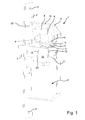
- Figure 1 shows a perspective view which illustrates the main parts of the lock mechanism arranged in a lock case.
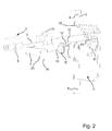
- Figure 2 illustrates an exploded view of the main parts for the lock mechanism.
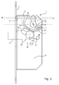
- Figure 3 shows a side view which illustrates the lock mechanism with the bolt fully extended.
- Figure 4 shows a side view which illustrates the lock mechanism with the bolt in an intermediate position.
- Figure 5 shows a side view which illustrates the lock mechanism with the bolt fully withdrawn.
- Figure 6 is equivalent to figure 3 but for a Scandinavian Oval cylinder.
- Figure 7a - d illustrates specific parts for the lock mechanism in figure 6 .
- Figure 8 is equivalent to figure 4 but for a Scandinavian Oval cylinder.
- Figure 9 is equivalent to figure 5 but for Scandinavian Oval cylinder.
- Figures 1 - 5 show a lock for a Euro Profile cylinder.
- This lock cylinder is drop shaped, and is extending through the lock case 1 from one side to the other.
- At an intermediate point of this drop shaped lock cylinder engagement means 5 are provided which are arranged such that they can perform a 360 degrees rotation.
- FIGS. 1 - 3 the lock case 1 with one cover removed is shown.
- the lock mechanism is arranged within the lock case 1 comprising two covers each covering one of the major surfaces.
- the lock case 1 is connected to a lock post 2 which is to be secured to e.g. a door.
- the lock post 2 is provided with holes 8 for e.g. screws to secure the lock post 2 to a door.
- the lock mechanism is arranged with an opening 6 for a lock cylinder 4.
- the lock cylinder will be extending out of the lock case 1 perpendicular to the plane of the paper when inserted in the opening 6.
- a rotational movement of a key inserted in the lock cylinder will cause rotation of engagement means 5, which are arranged such that they can be rotated 360 degrees.
- the engagement means 5 are in this case a protrusion in the shape of a tooth.
- the opening 6 for the lock cylinder 4 is formed by a first 18 and a second 19 plate.
- the lower part 9 of the lock case 1 illustrated in the figures is typically used for a handle and a latch controlled by this handle. This is, however, not essential for the invention and is therefore not shown.
- the lock mechanism is further provided with a toothed element 11 movable along a curved path 13 and connected with receiving means 12.
- the receiving means 12 will in this case have the form of a recess, e.g. a notch, fitting together with a protruding engagement means 5.
- the engagement means 5 and the receiving means 12 are formed to fit together, such that when they are in engagement, rotation of the engagement means 5 will give rise to a displacement of the toothed element 11 along the curved path 13.
- the curved path in which the toothed element 11 is movable is in this case formed as a groove 23 in said first plate 18 and in said second plate 19.
- the toothed element 11 is slidable in this groove 23 via a protrusion formed on the toothed element 11.
- the toothed element 11 is further in engagement with a toothed wheel 15 which is rotatably mounted.
- the toothed wheel 15 has a tap 16 eccentrically connected to the toothed wheel 15. This tap extends into a vertical slit provided in a base plate 30 of a bolt 3.
- a displacement of the toothed element 11 will cause a rotation of the toothed wheel 15, which by means of the tap 16 and the slit 20 will cause a displacement of the bolt 3.
- the bolt 3 is connected to the base plate 30 into which the slit 20 is arranged.
- the base plate being part of the bolt 3, is prepared for being displaced within the lock case 1 following movement of the tap 16 connected to the toothed wheel 15, when the tap 16 is moved in the slit 20.
- the base plate 30 is placed in front of the toothed wheel 15, and the slit 20 in the base plate 30 is preferably arranged such that the tap can be rotated with the toothed wheel for approximately 180 degrees.
- Figures 3-5 show three different positions of the bolt 3 depending on the position of the engagement means 5, and thereby on the position of a key in a lock cylinder.
- Figure 3 shows the lock mechanism with the bolt fully extended from the lock case 1.
- the toothed element 11 has been moved as far anticlockwise as possible, i.e. into the position opposite the direction of extension of the bolt 3 from the lock case 1.
- the teeth of the toothed element 11 in engagement with the toothed wheel 15 are the outer teeth at one end of the row of teeth on the toothed element 11.
- the engagement means 5 will loose contact or engagement with the receiving means 12 of the toothed element 11 when the engagement means 5 is moved further in an anticlockwise direction according to the figures.
- the engagement means 5 may, therefore, be rotated further in an anticlockwise direction without being engaged with the receiving means 12. This enables the key to rotate 360 degrees.
- a spring 21 is arranged between one fixed point of rotation on the lock case 1 and one point connected to the toothed wheel 15 such that the spring 21 will exert a force holding the toothed wheel 11 in the position shown in figure 3 where the bolt 3 is fully extended.
- the toothed element 11 is abutting against an end of the groove 23 preventing also the toothed wheel 15 from further clockwise rotation.
- the purpose is to prevent any movement of the toothed element 11 when the receiving means is not in engagement with the engagement means 5. It should be mentioned that the friction in the mechanism should be enough, but a spring is useful to provide extra security.
- Figure 4 shows the lock mechanism with the bolt in an intermediate position where it is being moved between the fully extended and the fully withdrawn positions.
- the teeth of the toothed element 11 which are in engagement with the toothed wheel 15, are some of the middle teeth in the row of teeth on the toothed element 11.
- the toothed element 11 will follow movement of the engagement means 5 in both clockwise and anticlockwise direction.
- the spring 21 will exert a force on the toothed wheel seeking to rotate it into one of the two end positions where the bolt 3 is either fully extended or fully withdrawn.
- the turning point which decides which position the spring load will seek to force the toothed wheel into, is when the tap is halfway between the two stable positions.
- Figure 5 shows the lock mechanism with the bolt fully withdrawn in the lock mechanism.
- the toothed element 11 has been moved as far clockwise as possible in the groove 23 forming the curved path 13, i.e. into the position in the direction where the bolt 3 is to be extended from the lock case 1.
- Further clockwise rotation of the engagement means 5 will course the engagement means 5 to loose contact or engagement with the receiving means 12 of the toothed element 11.
- the engagement means 5 are therefore free to complete their 360 degrees rotation.
- the total displacement of the bolt will be 20 mm or approximately 20 mm.
- the curved path 13 may have other shapes than part of a circle as illustrated. It may be formed from different circle parts having different radius and different centres. The important point is that when the engagement means 5 are rotated in one direction the engagement means 5 will engage with the receiving means 12 at one point of said curved path 13 and disengage from the receiving means 12 at a different point of said curved path.
- the toothed element 11 is preferably formed as a sliding part being slideable in the curved path 13. Alternatively, the toothed element 11 is pivotable about a point such that it is movable in the curved path 13.
- the lock cylinder is held in place by a screw 31 which is inserted through a hole 32 in the lock post 2.
- This screw is standard for all Euro-Profile cylinders and the centre axis B of this screw is according to the standard of the Euro-profile cylinder located perpendicular to and offset 19 mm from the centre axis A of the key of the lock cylinder as well as perpendicular to the lock post 2 of the lock mechanism.
- the toothed element and the curved path on which the toothed element slides are arranged such that the toothed element is located such that it does not conflict with this screw during the normal operation of the lock mechanism.
- this plane P will be located at an offset of 16.5 mm from the centre axis of the key of the lock cylinder.
- the plane is arranged parallel to the centre axis of the key of the lock cylinder and is arranged perpendicular to the plane of symmetry of the lock cylinder.
- the toothed element is arranged on one side of the screw which holds the euro-profile cylinder in place in the lock mechanism housing. It can also be seen in the current embodiment, that the toothed element is arranged on the same side of the plane P as the key of the lock cylinder. It can also be mentioned that in the current embodiment, the plane is located between the centre axis A of the key of the lock cylinder and the centre axis B of the screw 31. It could also be said that the plane P is located on the same side of the centre axis of the lock cylinder as the engagement means in the position of the lock cylinder in which the key can be removed from the lock cylinder.
- a Scandinavian Oval cylinder is used. This type of lock cylinder does not extend through the lock case 1. This means that two different cylinders can be entered into the opening 6 for cylinders, one from each side of the lock case 1.
- a transferring means 25 (shown in figure 7b ) is arranged for transferring the rotational position of both of the two cylinders to the engagement means 5.
- the transferring means is provided with a cross recess or a cross opening for correspondence with means on the cylinders rotatable with e.g. the key.
- the transferring means 25 may comprise the engagement means 5 or is in contact with the engagement means 5 when inserted in the opening 6 for cylinders.
- figure 7b shows a single transfer means 25.
- the two transfer means are arranged in the lock mechanism such that the two engagement means 5 point towards each other. In this way, the two lock cylinders can operate independently of each other.
- both cylinders have means for engaging with the transferring means 25.
- the transferring means 25 is arranged in the lock case 1, in the area between the first 18 and the second 19 plate.
- the first and second plate 18 and 19 of the embodiment shown in figures 1-5 and the first and second plate 18 and 19 of the embodiment shown in figures 6-9 are different due to the differences in the locking cylinders.
- the locking mechanism can easily be changed from a Euro-Profile cylinder lock mechanism to a Scandinavian Oval cylinder lock mechanism.
- the bolt 3 has been an integral component of the lock mechanism and has been arranged inside the lock case and is extendable from the lock case 1.
- the bolt 3 could also be arranged distant from the lock case 1.
- the position of the bolt 3, i.e. extended or withdrawn, could then be controlled via a rod controlled by the position of the toothed wheel 15.
- a bolt 3 placed in the lock case 1 as shown in the figures could also be supplemented by one or two further external bolts controlled through one or two rods.
Landscapes
- Engineering & Computer Science (AREA)
- Structural Engineering (AREA)
- Lock And Its Accessories (AREA)
- Centrifugal Separators (AREA)
- External Artificial Organs (AREA)
- Steering Controls (AREA)
- Holders For Apparel And Elements Relating To Apparel (AREA)
- Switches With Compound Operations (AREA)
- Pens And Brushes (AREA)
Abstract
Description
- The invention concerns a lock mechanism for a door. The lock mechanism is prepared for receiving a lock cylinder with rotatable engagement means.
- Such lock mechanisms are known from e.g.
WO 2004/040086 A1 , and are typically housed in a lock case secured to a lock post which is fixedly mounted to a door. - According to some standards it should be possible to rotate the key for 360 degrees when it is inserted in the lock cylinder. Furthermore, for many applications it is important to have a relatively large displacement of the bolt. For example some standards demand a minimum of 20 mm bolt displacement. This displacement must be achieved by one rotation of the key, i.e. 360 degrees. If more than one rotation of the key is needed to achieve the 20 mm displacement, this may not always be performed in practice and this therefore implies a security risk.
- Another issue is that the direction of rotation of the key should be logical to the user. Most users find that when locking a door, the upper part of the key should be moved towards the door post or in other words in the direction in which the bolt extends from the lock mechanism. Furthermore, it is advantageous if the same lock mechanism can be used with different types of lock cylinders. Two examples of common lock cylinders are the "Euro Profile cylinder" and the "Scandinavian Oval cylinder".
- All this has been achieved by a locking mechanism arranged according to
claim 1. - In a preferred embodiment of the invention the engagement can also be rotated in the opposite direction whereby the engagement means will engage with the receiving means at the second point on said curved path and disengage from the receiving means at the first point on said curved path.
- In a preferred embodiment of the invention the engagement means could be a protrusion. This will be the case for the Euro Profile cylinder. When the engagement means is a protrusion, the receiving means can be a recess in the toothed element.
- In a preferred embodiment, the toothed element of the lock mechanism can be arranged to be slidable along said curved path. This offers a simple and reliable construction.
- In a further embodiment the part of said curved path along which the engagement means could be in engagement with the receiving means, could have an average radius which is larger than the radius of rotation of said engagement means, and which has a centre different from the centre of rotation of said engagement means. This is a simple and reliable arrangement for ensuring an accurate engagement and disengagement between the engagement means and the receiving means.
- In a further embodiment the toothed wheel can be connected with a tap which extends perpendicular to the plane of the toothed wheel into a slit connected to said bolt, such that when the toothed wheel is rotated, the rotational movement of the wheel is transferred to a rectilinear or substantially rectilinear displacement of said bolt. This is a simple and reliable arrangement for transferring the rotational movement of the toothed wheel to a displacement of the bolt. The toothed wheel including the tap is furthermore a simple way of transferring the movement of the toothed element to the displacement of the bolt.
- In a further embodiment of the invention the slit could extend in its longitudinal direction transversely to the direction of displacement of the bolt. Thereby the component of the movement of the tap parallel with the direction of displacement of the bolt is transferred directly to the bolt. At the same time, due to the slit, the component of the movement transverse to the displacement of the bolt will not influence the displacement of the bolt.
- In a further embodiment the lock mechanism is provided with means for preventing the bolt from being pressed into the lock case when the bolt is in a fully extended position. Thereby, the security of the lock mechanism is further improved.
- In a further embodiment, the means for preventing the bolt from being pressed into the lock case is the tap connected with said toothed wheel and extending into said slit. Preferably the tap has an end position when the bolt is fully extended from the lock mechanism, said end position is placed on or above a line being parallel or substantially parallel with the direction of displacement of said bolt and passing through the centre of rotation of said toothed wheel, thus obtaining a simple and reliable solution.
- In a further embodiment the position of said toothed element is biased such that the toothed element has two stable positions where the engagement means is disengaged from said receiving means. This will prevent accidental movement of the toothed element when the engagement means is disengaged from the receiving means. Such biasing could be by means of a spring load.
- Embodiments of the invention are now described in further detail with reference to the figures. These embodiments are not limiting for the scope of protection defined in the claims.
-
Figure 1 shows a perspective view which illustrates the main parts of the lock mechanism arranged in a lock case. -
Figure 2 illustrates an exploded view of the main parts for the lock mechanism. -
Figure 3 shows a side view which illustrates the lock mechanism with the bolt fully extended. -
Figure 4 shows a side view which illustrates the lock mechanism with the bolt in an intermediate position. -
Figure 5 shows a side view which illustrates the lock mechanism with the bolt fully withdrawn. -
Figure 6 is equivalent tofigure 3 but for a Scandinavian Oval cylinder. -
Figure 7a - d illustrates specific parts for the lock mechanism infigure 6 . -
Figure 8 is equivalent tofigure 4 but for a Scandinavian Oval cylinder. -
Figure 9 is equivalent tofigure 5 but for Scandinavian Oval cylinder. - It should be noted that terms of orientation, for example above, clockwise etc. are to be interpreted according to the orientations of the figures. It should be understood by the person skilled in the art that the devices could be installed in other orientations.
-
Figures 1 - 5 show a lock for a Euro Profile cylinder. This lock cylinder is drop shaped, and is extending through thelock case 1 from one side to the other. At an intermediate point of this drop shaped lock cylinder engagement means 5 are provided which are arranged such that they can perform a 360 degrees rotation. - In
figures 1 - 3 thelock case 1 with one cover removed is shown. The lock mechanism is arranged within thelock case 1 comprising two covers each covering one of the major surfaces. Thelock case 1 is connected to alock post 2 which is to be secured to e.g. a door. Thelock post 2 is provided withholes 8 for e.g. screws to secure thelock post 2 to a door. Within thelock case 1 the lock mechanism is arranged with anopening 6 for alock cylinder 4. The lock cylinder will be extending out of thelock case 1 perpendicular to the plane of the paper when inserted in theopening 6. A rotational movement of a key inserted in the lock cylinder will cause rotation of engagement means 5, which are arranged such that they can be rotated 360 degrees. The engagement means 5 are in this case a protrusion in the shape of a tooth. - The opening 6 for the
lock cylinder 4 is formed by a first 18 and a second 19 plate. - The
lower part 9 of thelock case 1 illustrated in the figures is typically used for a handle and a latch controlled by this handle. This is, however, not essential for the invention and is therefore not shown. - The lock mechanism is further provided with a
toothed element 11 movable along acurved path 13 and connected withreceiving means 12. Thereceiving means 12 will in this case have the form of a recess, e.g. a notch, fitting together with a protruding engagement means 5. The engagement means 5 and the receivingmeans 12 are formed to fit together, such that when they are in engagement, rotation of the engagement means 5 will give rise to a displacement of thetoothed element 11 along thecurved path 13. - The curved path in which the
toothed element 11 is movable is in this case formed as agroove 23 in saidfirst plate 18 and in saidsecond plate 19. Thetoothed element 11 is slidable in thisgroove 23 via a protrusion formed on thetoothed element 11. Thetoothed element 11 is further in engagement with atoothed wheel 15 which is rotatably mounted. Thetoothed wheel 15 has atap 16 eccentrically connected to thetoothed wheel 15. This tap extends into a vertical slit provided in abase plate 30 of abolt 3. - A displacement of the
toothed element 11 will cause a rotation of thetoothed wheel 15, which by means of thetap 16 and theslit 20 will cause a displacement of thebolt 3. - The
bolt 3 is connected to thebase plate 30 into which theslit 20 is arranged. The base plate, being part of thebolt 3, is prepared for being displaced within thelock case 1 following movement of thetap 16 connected to thetoothed wheel 15, when thetap 16 is moved in theslit 20. As illustrated infigure 3 thebase plate 30 is placed in front of thetoothed wheel 15, and theslit 20 in thebase plate 30 is preferably arranged such that the tap can be rotated with the toothed wheel for approximately 180 degrees. -
Figures 3-5 show three different positions of thebolt 3 depending on the position of the engagement means 5, and thereby on the position of a key in a lock cylinder. -
Figure 3 shows the lock mechanism with the bolt fully extended from thelock case 1. In this position thetoothed element 11 has been moved as far anticlockwise as possible, i.e. into the position opposite the direction of extension of thebolt 3 from thelock case 1. This means that the teeth of thetoothed element 11 in engagement with thetoothed wheel 15 are the outer teeth at one end of the row of teeth on thetoothed element 11. This is the position where the engagement means 5 cannot move thetoothed element 11 further in an anticlockwise direction. The engagement means 5 will loose contact or engagement with the receiving means 12 of thetoothed element 11 when the engagement means 5 is moved further in an anticlockwise direction according to the figures. The engagement means 5 may, therefore, be rotated further in an anticlockwise direction without being engaged with the receiving means 12. This enables the key to rotate 360 degrees. The rotation stops when the engagement means 5 abuts thetoothed element 11 again. This is shown by the tap shown with dotted lines infigure 3 . - With the position of the
toothed element 11 shown infigure 3 , the position of thetoothed wheel 15 and thebolt 3 will also be given. Aspring 21 is arranged between one fixed point of rotation on thelock case 1 and one point connected to thetoothed wheel 15 such that thespring 21 will exert a force holding thetoothed wheel 11 in the position shown infigure 3 where thebolt 3 is fully extended. In this position thetoothed element 11 is abutting against an end of thegroove 23 preventing also thetoothed wheel 15 from further clockwise rotation. The purpose is to prevent any movement of thetoothed element 11 when the receiving means is not in engagement with the engagement means 5. It should be mentioned that the friction in the mechanism should be enough, but a spring is useful to provide extra security. - When the
bolt 3 is in this fully extended position as shown infigure 3 thetap 16 connected to thetoothed wheel 15 will be positioned such that any attempt to force thebolt 3 into thelock case 1 will result in a force on thetap 16 directed directly towards the centre of rotation of thetoothed wheel 15. Therefore there will be no component of this force acting tangentially on the toothed wheel, and therefore it cannot be rotated by such a force on the bolt. The lock mechanism is therefore self-locking. -
Figure 4 shows the lock mechanism with the bolt in an intermediate position where it is being moved between the fully extended and the fully withdrawn positions. In this position the teeth of thetoothed element 11 which are in engagement with thetoothed wheel 15, are some of the middle teeth in the row of teeth on thetoothed element 11. In this position, thetoothed element 11 will follow movement of the engagement means 5 in both clockwise and anticlockwise direction. Thespring 21 will exert a force on the toothed wheel seeking to rotate it into one of the two end positions where thebolt 3 is either fully extended or fully withdrawn. The turning point which decides which position the spring load will seek to force the toothed wheel into, is when the tap is halfway between the two stable positions. - It is seen from
figures 3 - 5 that due to the dimensions and placement of theslit 20 it is only possible to move thebolt 3 from fully extended to fully withdrawn by rotating thetoothed wheel 15 anticlockwise. Infigure 3 thetap 16 is prevented by theslit 20 from being moved upwards. Likewise, it is only possible to move the bolt from fully withdrawn to fully extended by rotating thetoothed wheel 15 clockwise. Infigure 5 thetap 16 is prevented by theslit 20 from being moved upwards. -
Figure 5 shows the lock mechanism with the bolt fully withdrawn in the lock mechanism. In this position thetoothed element 11 has been moved as far clockwise as possible in thegroove 23 forming thecurved path 13, i.e. into the position in the direction where thebolt 3 is to be extended from thelock case 1. Further clockwise rotation of the engagement means 5 will course the engagement means 5 to loose contact or engagement with the receiving means 12 of thetoothed element 11. The engagement means 5 are therefore free to complete their 360 degrees rotation. - In this position of the key, the
bolt 3 is fully withdrawn. Thespring 21 will be holding thetoothed wheel 11 in the stable position shown infigure 5 . In this position thetoothed element 11 is abutting against the other end of the groove forming thecurved path 13 preventing also thetoothed wheel 15 from further anti clockwise rotation. Furthermore, thetap 16 abuts against the top of theslit 20 also preventing further anticlockwise rotation of the toothed wheel. - It is seen from
figures 3 - 5 that the movement between thetoothed element 11 and the toothed wheel ensures that turning the upper part of the key towards thelock post 2 will extend thebolt 3 from thelock case 1, thereby locking the door in which the lock mechanism has been arranged. - Correspondingly, turning the upper part of the key away from the
lock post 2 will unlock the door by withdrawing thebolt 3 into thelock case 1. This is also the turning direction of the key for locking and unlocking, respectively, which intuitively will be the most logical turning direction for most people. - In
figures 3 - 5 thecircle 14 along which the engagement means 5 will rotate is indicated with dotted lines. It is seen that the radius of this circle is clearly smaller than the radius of thecurved path 13 of the receiving means 12. Also, the centre of thecurved path 13 is located differently than the centre for the rotation of the engagement means 5. This arrangement of different radius and different centre of rotation facilitate that the engagement means 5 are only in engagement with the receiving means 12 for a part of a 360 degrees full circular rotation. This part of engagement is for the Euro Profile cylinder 110 degrees of the rotational movement of the engagement means 5 and for the Scandinavian Oval cylinder this part of the engagement is 125 degrees of the rotational movement of the engagement means 5. This means that 110 or 125 degrees of the rotation of the key is applied for displacement of thebolt 3, and during this part of the rotation there will be proportionality between the rotational position of the key and the position of thebolt 3. In a preferred embodiment of the lock mechanism the total displacement of the bolt will be 20 mm or approximately 20 mm. - The
curved path 13 may have other shapes than part of a circle as illustrated. It may be formed from different circle parts having different radius and different centres. The important point is that when the engagement means 5 are rotated in one direction the engagement means 5 will engage with the receiving means 12 at one point of saidcurved path 13 and disengage from the receiving means 12 at a different point of said curved path. - The
toothed element 11 is preferably formed as a sliding part being slideable in thecurved path 13. Alternatively, thetoothed element 11 is pivotable about a point such that it is movable in thecurved path 13. - It can also be seen from
figures 3-5 that the lock cylinder is held in place by ascrew 31 which is inserted through ahole 32 in thelock post 2. This screw is standard for all Euro-Profile cylinders and the centre axis B of this screw is according to the standard of the Euro-profile cylinder located perpendicular to and offset 19 mm from the centre axis A of the key of the lock cylinder as well as perpendicular to thelock post 2 of the lock mechanism. In order for the lock mechanism to function with a Euro-Profile cylinder, the toothed element and the curved path on which the toothed element slides, are arranged such that the toothed element is located such that it does not conflict with this screw during the normal operation of the lock mechanism. - One way of doing this is to arrange the toothed element and the curved path such that the toothed element, during normal operation, is entirely located on one side of a plane which is arranged tangent to the screw. In this way, the toothed element will not come into contact with the screw. Since the screw used is an M5 (5mm diameter) screw, this plane P will be located at an offset of 16.5 mm from the centre axis of the key of the lock cylinder. In the embodiment shown, the plane is arranged parallel to the centre axis of the key of the lock cylinder and is arranged perpendicular to the plane of symmetry of the lock cylinder. Another way of saying this is to say that the toothed element is arranged on one side of the screw which holds the euro-profile cylinder in place in the lock mechanism housing. It can also be seen in the current embodiment, that the toothed element is arranged on the same side of the plane P as the key of the lock cylinder. It can also be mentioned that in the current embodiment, the plane is located between the centre axis A of the key of the lock cylinder and the centre axis B of the
screw 31. It could also be said that the plane P is located on the same side of the centre axis of the lock cylinder as the engagement means in the position of the lock cylinder in which the key can be removed from the lock cylinder. - It should be noted that this is important for the current invention, since it is often desired to use a Euro-Profile cylinder in a lock mechanism. This is especially true in Europe. Many other forms of locking mechanism previously available are not suitable for use with a Euro-profile cylinder. For example
US 3,175,376 shows a ring formed toothed element which encircles the lock cylinder. Such a ring formed toothed element will not work with a euro-profile cylinder since the toothed element will conflict with the screw for holding the Euro-Profile cylinder. The ring formed toothed element ofUS 3,175,376 will only be suitable for use together with a US type lock cylinder. - In
figure 6 - 9 a Scandinavian Oval cylinder is used. This type of lock cylinder does not extend through thelock case 1. This means that two different cylinders can be entered into theopening 6 for cylinders, one from each side of thelock case 1. Inside theopening 6 for cylinders a transferring means 25 (shown infigure 7b ) is arranged for transferring the rotational position of both of the two cylinders to the engagement means 5. The transferring means is provided with a cross recess or a cross opening for correspondence with means on the cylinders rotatable with e.g. the key. The transferring means 25 may comprise the engagement means 5 or is in contact with the engagement means 5 when inserted in theopening 6 for cylinders. It should be noted thatfigure 7b shows a single transfer means 25. In the actual device offigure 6 ,8 and 9 , there are two transfer means 25, one being a mirror image of the other. The two transfer means are arranged in the lock mechanism such that the two engagement means 5 point towards each other. In this way, the two lock cylinders can operate independently of each other. - Often the cylinder accessible from outside the door is to be opened by a key, while the cylinder accessible from inside the door is rotatable by a simple knob. Both cylinders have means for engaging with the transferring means 25.
- When assembling the lock mechanism the transferring means 25 is arranged in the
lock case 1, in the area between the first 18 and the second 19 plate. Note that the first andsecond plate figures 1-5 and the first andsecond plate figures 6-9 are different due to the differences in the locking cylinders. By exhanging the first and second plate of the embodiment offigures 1-5 with the transfer means 25 and the first and second plate of the embodiment shown infigures 6-9 , the locking mechanism can easily be changed from a Euro-Profile cylinder lock mechanism to a Scandinavian Oval cylinder lock mechanism. - It should also be noted that as the person skilled in the art will know, a Scandinavian Oval cylinder as shown in this embodiment is held in place in the lock mechanism by two screws (not shown) having axes which are parallel to the centre axis of the lock cylinder and being arranged in the portion of the lock cylinder above the key (according to the orientation shown in the figures). These screws also impose significant restrictions on the design of the lock mechanism since no moving parts can be in conflict with these screws. It is therefore a significant challenge to provide a lock mechanism which can work with both a Scandinavian Oval cylinder as well as a Euro-Profile cylinder.
- In the embodiments shown in the figures the
bolt 3 has been an integral component of the lock mechanism and has been arranged inside the lock case and is extendable from thelock case 1. However, it should be clear to the person skilled in the art that thebolt 3 could also be arranged distant from thelock case 1. The position of thebolt 3, i.e. extended or withdrawn, could then be controlled via a rod controlled by the position of thetoothed wheel 15. Abolt 3 placed in thelock case 1 as shown in the figures could also be supplemented by one or two further external bolts controlled through one or two rods.
Claims (11)
- A lock mechanism for a door or window, said lock mechanism being prepared for receiving a lock cylinder 4 with engagement means 5 which are rotatable 360 degrees, said lock mechanism comprising- a toothed element 11 being movable along a curved path 13 and having receiving means 12 prepared for engaging with said engagement means 5, said curved path 13 having a shape such that when the engagement means 5 are rotated in one direction the engagement means 5 will engage with the receiving means 12 at a first point on said curved path 13 and disengage from the receiving means 12 at a second point on said curved path 13, such that the engagement means 5 can rotate 360 degrees, and said toothed element being arranged such that during normal operation of the lock mechanism, the toothed element is entirely located on one side of a plane which is arranged perpendicular to the plane of symmetry of the lock cylinder and parallel to the centre axis of the key of the lock cylinder and offset from the centre axis of the key of the lock cylinder by 16.5 mm;- a toothed wheel 15 in engagement with said toothed element 11 such that displacement of said toothed element 11 along said curved path 13 causes a rotation of said toothed wheel 15; and- a bolt 3 displaceable by a rotational movement of said toothed wheel 15.
- A lock mechanism according to claim 1, wherein when the engagement means 5 are rotated in the opposite direction, the engagement means 5 will engage with the receiving means 12 at the second point on said curved path 13 and disengage from the receiving means 12 at the first point on said curved path 13.
- A lock mechanism according to claim 1 or 2, wherein said engagement 5 means is a protrusion, and said receiving means 12 is a recess in the toothed element 11.
- A lock mechanism according to any one of the previous claims wherein said toothed element 11 is arranged to be slidable along said curved path 13.
- A lock mechanism according to any one of the previous claims, wherein the part of said curved path 13 along which the engagement means 5 will be in engagement with the receiving means 12, has an average radius which is larger than the radius of rotation of said engagement means 5, and which has a centre different from the centre of rotation of said engagement means 5.
- A lock mechanism according to any one of the previous claims, wherein said toothed wheel 15 is connected with a tap 16 extending perpendicular to the plane of the toothed wheel 15 into a slit 20 connected to said bolt, such that when the toothed wheel 15 is rotated, this rotational movement is transferred to a rectilinear or substantially rectilinear displacement of said bolt 3.
- A lock mechanism according to claim 6, wherein said slit 20 is extending in its longitudinal direction transversely to the direction of displacement of said bolt 3.
- A lock mechanism according to any one of the previous claims, wherein the lock mechanism is provided with means for preventing the bolt 3 from being pressed into the lock case 1 when the bolt 3 is in its extended position.
- A lock mechanism according to claims 6 - 8, wherein said means for preventing the bolt 3 from being pressed into the lock 1 case is the tap 16 connected with said toothed wheel 15 and extending into said slit 20.
- A lock mechanism according to claim 9, wherein said tap 16 has an end position when the bolt 3 is fully extended from the lock mechanism, said end position is placed on or above a line being parallel or substantially parallel with the direction of displacement of said bolt 3 and passing through the centre of rotation of said toothed wheel 15.
- A lock mechanism according to any one of the previous claims, wherein the position of said toothed element 11 is biased in its two end positions, such that the toothed element 11 has two stable positions where the engagement means 5 is disengaged from said receiving means 12.
Applications Claiming Priority (1)
| Application Number | Priority Date | Filing Date | Title |
|---|---|---|---|
| PCT/DK2007/000336 WO2009003471A1 (en) | 2007-07-03 | 2007-07-03 | A lock mechanism |
Publications (2)
| Publication Number | Publication Date |
|---|---|
| EP2011937A1 true EP2011937A1 (en) | 2009-01-07 |
| EP2011937B1 EP2011937B1 (en) | 2010-06-23 |
Family
ID=38984461
Family Applications (1)
| Application Number | Title | Priority Date | Filing Date |
|---|---|---|---|
| EP08159661A Not-in-force EP2011937B1 (en) | 2007-07-03 | 2008-07-03 | A lock mechanism |
Country Status (5)
| Country | Link |
|---|---|
| EP (1) | EP2011937B1 (en) |
| AT (1) | ATE472028T1 (en) |
| DE (1) | DE602008001581D1 (en) |
| DK (1) | DK2011937T3 (en) |
| WO (1) | WO2009003471A1 (en) |
Cited By (2)
| Publication number | Priority date | Publication date | Assignee | Title |
|---|---|---|---|---|
| EP2213818A3 (en) * | 2009-01-28 | 2012-04-25 | DORMA GmbH + Co. KG | Lock, in particular slideable dead bolt lock, with improved protection |
| EP2261445A3 (en) * | 2009-06-03 | 2014-10-29 | Dorma GmbH + Co. KG | Lock in particular door lock with improved locking mechanism |
Citations (9)
| Publication number | Priority date | Publication date | Assignee | Title |
|---|---|---|---|---|
| US3175376A (en) | 1961-07-17 | 1965-03-30 | Adams Rite Mfg Company | Lock mechanism |
| NL7807082A (en) * | 1978-06-30 | 1980-01-03 | Lips Slotenfab | Heavy duty door lock - has auxiliary lug with notch engaged by lug on cylinder passing through housing |
| DE3731879A1 (en) * | 1987-09-23 | 1989-04-27 | Fliether Karl Gmbh & Co | Door lock actuable by lock cylinder |
| FR2711712A1 (en) * | 1993-10-21 | 1995-05-05 | Deny | Lock having a rotary driver |
| GB2288207A (en) * | 1994-04-09 | 1995-10-11 | Chubb Locks Ltd | A mortice lock with auxiliary thrower having precise detent means |
| DE19538320A1 (en) * | 1994-10-27 | 1996-05-02 | Hueppe Form Sonnenschutz | Locking mechanism with rotating key bit for door |
| EP0792980A1 (en) * | 1996-02-29 | 1997-09-03 | DORMA GmbH + Co. KG | Lock |
| FR2772816A1 (en) * | 1997-12-19 | 1999-06-25 | Vak Picard | Lock with rotary drive for sliding elements such as long bolts |
| WO2004040086A1 (en) | 2002-10-30 | 2004-05-13 | Ccz International Pte Ltd. | A lock mechanism |
-
2007
- 2007-07-03 WO PCT/DK2007/000336 patent/WO2009003471A1/en active Application Filing
-
2008
- 2008-07-03 DK DK08159661.1T patent/DK2011937T3/en active
- 2008-07-03 DE DE602008001581T patent/DE602008001581D1/en active Active
- 2008-07-03 AT AT08159661T patent/ATE472028T1/en not_active IP Right Cessation
- 2008-07-03 EP EP08159661A patent/EP2011937B1/en not_active Not-in-force
Patent Citations (9)
| Publication number | Priority date | Publication date | Assignee | Title |
|---|---|---|---|---|
| US3175376A (en) | 1961-07-17 | 1965-03-30 | Adams Rite Mfg Company | Lock mechanism |
| NL7807082A (en) * | 1978-06-30 | 1980-01-03 | Lips Slotenfab | Heavy duty door lock - has auxiliary lug with notch engaged by lug on cylinder passing through housing |
| DE3731879A1 (en) * | 1987-09-23 | 1989-04-27 | Fliether Karl Gmbh & Co | Door lock actuable by lock cylinder |
| FR2711712A1 (en) * | 1993-10-21 | 1995-05-05 | Deny | Lock having a rotary driver |
| GB2288207A (en) * | 1994-04-09 | 1995-10-11 | Chubb Locks Ltd | A mortice lock with auxiliary thrower having precise detent means |
| DE19538320A1 (en) * | 1994-10-27 | 1996-05-02 | Hueppe Form Sonnenschutz | Locking mechanism with rotating key bit for door |
| EP0792980A1 (en) * | 1996-02-29 | 1997-09-03 | DORMA GmbH + Co. KG | Lock |
| FR2772816A1 (en) * | 1997-12-19 | 1999-06-25 | Vak Picard | Lock with rotary drive for sliding elements such as long bolts |
| WO2004040086A1 (en) | 2002-10-30 | 2004-05-13 | Ccz International Pte Ltd. | A lock mechanism |
Cited By (2)
| Publication number | Priority date | Publication date | Assignee | Title |
|---|---|---|---|---|
| EP2213818A3 (en) * | 2009-01-28 | 2012-04-25 | DORMA GmbH + Co. KG | Lock, in particular slideable dead bolt lock, with improved protection |
| EP2261445A3 (en) * | 2009-06-03 | 2014-10-29 | Dorma GmbH + Co. KG | Lock in particular door lock with improved locking mechanism |
Also Published As
| Publication number | Publication date |
|---|---|
| DK2011937T3 (en) | 2010-09-06 |
| DE602008001581D1 (en) | 2010-08-05 |
| ATE472028T1 (en) | 2010-07-15 |
| WO2009003471A1 (en) | 2009-01-08 |
| EP2011937B1 (en) | 2010-06-23 |
Similar Documents
| Publication | Publication Date | Title |
|---|---|---|
| EP3607160B1 (en) | Electronically controlled padlock | |
| KR100686909B1 (en) | Security classroom function lock mechanism | |
| EP3899175B1 (en) | Door lock arrangement with controllable handle operation | |
| CA2215950C (en) | Low profile handle | |
| WO1993025788A1 (en) | Latch and lockset system | |
| US9284749B2 (en) | Door lock assembly | |
| US20100244463A1 (en) | Dual Cam Magnetic Latch System | |
| CA2677974C (en) | Locker lock | |
| CN112262246B (en) | Electric drive mechanism for actuating a lock | |
| EP2011937B1 (en) | A lock mechanism | |
| AU2013248267B1 (en) | Lock system | |
| US4646547A (en) | Dead bolt combination lock | |
| GB2606302A (en) | Combination lock | |
| AU2006235659A1 (en) | Closing device | |
| FI3498941T3 (en) | Actuating handle with blocking device | |
| WO2000049255A1 (en) | Lock device | |
| WO2009113949A1 (en) | Lock with spring bolt | |
| EP4345230A1 (en) | Handle lock assembly having an interchangeable handle | |
| CN109281548B (en) | Deadbolt assembly for a door | |
| EP3323965B1 (en) | Dead bolt locking mechanism | |
| JP2021518501A (en) | Lock assembly | |
| SE2051322A1 (en) | Locking device for mechanical and non-mechanical activation of a locking bolt | |
| JP2006029019A (en) | Button lock | |
| NZ757437B2 (en) | Electronically controlled padlock | |
| GB2427647A (en) | Electrically operated lock |
Legal Events
| Date | Code | Title | Description |
|---|---|---|---|
| PUAI | Public reference made under article 153(3) epc to a published international application that has entered the european phase |
Free format text: ORIGINAL CODE: 0009012 |
|
| AK | Designated contracting states |
Kind code of ref document: A1 Designated state(s): AT BE BG CH CY CZ DE DK EE ES FI FR GB GR HR HU IE IS IT LI LT LU LV MC MT NL NO PL PT RO SE SI SK TR |
|
| AX | Request for extension of the european patent |
Extension state: AL BA MK RS |
|
| 17P | Request for examination filed |
Effective date: 20090702 |
|
| AKX | Designation fees paid |
Designated state(s): AT BE BG CH CY CZ DE DK EE ES FI FR GB GR HR HU IE IS IT LI LT LU LV MC MT NL NO PL PT RO SE SI SK TR |
|
| GRAP | Despatch of communication of intention to grant a patent |
Free format text: ORIGINAL CODE: EPIDOSNIGR1 |
|
| GRAS | Grant fee paid |
Free format text: ORIGINAL CODE: EPIDOSNIGR3 |
|
| GRAA | (expected) grant |
Free format text: ORIGINAL CODE: 0009210 |
|
| AK | Designated contracting states |
Kind code of ref document: B1 Designated state(s): AT BE BG CH CY CZ DE DK EE ES FI FR GB GR HR HU IE IS IT LI LT LU LV MC MT NL NO PL PT RO SE SI SK TR |
|
| REG | Reference to a national code |
Ref country code: CH Ref legal event code: EP |
|
| REG | Reference to a national code |
Ref country code: IE Ref legal event code: FG4D |
|
| REF | Corresponds to: |
Ref document number: 602008001581 Country of ref document: DE Date of ref document: 20100805 Kind code of ref document: P |
|
| REG | Reference to a national code |
Ref country code: DK Ref legal event code: T3 |
|
| REG | Reference to a national code |
Ref country code: NO Ref legal event code: T2 Effective date: 20100623 |
|
| REG | Reference to a national code |
Ref country code: SE Ref legal event code: TRGR |
|
| REG | Reference to a national code |
Ref country code: NL Ref legal event code: VDEP Effective date: 20100623 |
|
| PG25 | Lapsed in a contracting state [announced via postgrant information from national office to epo] |
Ref country code: LT Free format text: LAPSE BECAUSE OF FAILURE TO SUBMIT A TRANSLATION OF THE DESCRIPTION OR TO PAY THE FEE WITHIN THE PRESCRIBED TIME-LIMIT Effective date: 20100623 |
|
| LTIE | Lt: invalidation of european patent or patent extension |
Effective date: 20100623 |
|
| PG25 | Lapsed in a contracting state [announced via postgrant information from national office to epo] |
Ref country code: SI Free format text: LAPSE BECAUSE OF FAILURE TO SUBMIT A TRANSLATION OF THE DESCRIPTION OR TO PAY THE FEE WITHIN THE PRESCRIBED TIME-LIMIT Effective date: 20100623 Ref country code: AT Free format text: LAPSE BECAUSE OF FAILURE TO SUBMIT A TRANSLATION OF THE DESCRIPTION OR TO PAY THE FEE WITHIN THE PRESCRIBED TIME-LIMIT Effective date: 20100623 Ref country code: FI Free format text: LAPSE BECAUSE OF FAILURE TO SUBMIT A TRANSLATION OF THE DESCRIPTION OR TO PAY THE FEE WITHIN THE PRESCRIBED TIME-LIMIT Effective date: 20100623 Ref country code: HR Free format text: LAPSE BECAUSE OF FAILURE TO SUBMIT A TRANSLATION OF THE DESCRIPTION OR TO PAY THE FEE WITHIN THE PRESCRIBED TIME-LIMIT Effective date: 20100623 Ref country code: LV Free format text: LAPSE BECAUSE OF FAILURE TO SUBMIT A TRANSLATION OF THE DESCRIPTION OR TO PAY THE FEE WITHIN THE PRESCRIBED TIME-LIMIT Effective date: 20100623 |
|
| PG25 | Lapsed in a contracting state [announced via postgrant information from national office to epo] |
Ref country code: PL Free format text: LAPSE BECAUSE OF FAILURE TO SUBMIT A TRANSLATION OF THE DESCRIPTION OR TO PAY THE FEE WITHIN THE PRESCRIBED TIME-LIMIT Effective date: 20100623 |
|
| PG25 | Lapsed in a contracting state [announced via postgrant information from national office to epo] |
Ref country code: NL Free format text: LAPSE BECAUSE OF FAILURE TO SUBMIT A TRANSLATION OF THE DESCRIPTION OR TO PAY THE FEE WITHIN THE PRESCRIBED TIME-LIMIT Effective date: 20100623 Ref country code: EE Free format text: LAPSE BECAUSE OF FAILURE TO SUBMIT A TRANSLATION OF THE DESCRIPTION OR TO PAY THE FEE WITHIN THE PRESCRIBED TIME-LIMIT Effective date: 20100623 |
|
| PG25 | Lapsed in a contracting state [announced via postgrant information from national office to epo] |
Ref country code: BE Free format text: LAPSE BECAUSE OF FAILURE TO SUBMIT A TRANSLATION OF THE DESCRIPTION OR TO PAY THE FEE WITHIN THE PRESCRIBED TIME-LIMIT Effective date: 20100623 Ref country code: SK Free format text: LAPSE BECAUSE OF FAILURE TO SUBMIT A TRANSLATION OF THE DESCRIPTION OR TO PAY THE FEE WITHIN THE PRESCRIBED TIME-LIMIT Effective date: 20100623 Ref country code: RO Free format text: LAPSE BECAUSE OF FAILURE TO SUBMIT A TRANSLATION OF THE DESCRIPTION OR TO PAY THE FEE WITHIN THE PRESCRIBED TIME-LIMIT Effective date: 20100623 Ref country code: MC Free format text: LAPSE BECAUSE OF NON-PAYMENT OF DUE FEES Effective date: 20100731 Ref country code: IS Free format text: LAPSE BECAUSE OF FAILURE TO SUBMIT A TRANSLATION OF THE DESCRIPTION OR TO PAY THE FEE WITHIN THE PRESCRIBED TIME-LIMIT Effective date: 20101023 Ref country code: CZ Free format text: LAPSE BECAUSE OF FAILURE TO SUBMIT A TRANSLATION OF THE DESCRIPTION OR TO PAY THE FEE WITHIN THE PRESCRIBED TIME-LIMIT Effective date: 20100623 Ref country code: CY Free format text: LAPSE BECAUSE OF FAILURE TO SUBMIT A TRANSLATION OF THE DESCRIPTION OR TO PAY THE FEE WITHIN THE PRESCRIBED TIME-LIMIT Effective date: 20100623 |
|
| PG25 | Lapsed in a contracting state [announced via postgrant information from national office to epo] |
Ref country code: IT Free format text: LAPSE BECAUSE OF FAILURE TO SUBMIT A TRANSLATION OF THE DESCRIPTION OR TO PAY THE FEE WITHIN THE PRESCRIBED TIME-LIMIT Effective date: 20100623 |
|
| PLBE | No opposition filed within time limit |
Free format text: ORIGINAL CODE: 0009261 |
|
| STAA | Information on the status of an ep patent application or granted ep patent |
Free format text: STATUS: NO OPPOSITION FILED WITHIN TIME LIMIT |
|
| PG25 | Lapsed in a contracting state [announced via postgrant information from national office to epo] |
Ref country code: GR Free format text: LAPSE BECAUSE OF FAILURE TO SUBMIT A TRANSLATION OF THE DESCRIPTION OR TO PAY THE FEE WITHIN THE PRESCRIBED TIME-LIMIT Effective date: 20100924 |
|
| 26N | No opposition filed |
Effective date: 20110324 |
|
| REG | Reference to a national code |
Ref country code: FR Ref legal event code: ST Effective date: 20110531 |
|
| REG | Reference to a national code |
Ref country code: DE Ref legal event code: R097 Ref document number: 602008001581 Country of ref document: DE Effective date: 20110323 |
|
| PG25 | Lapsed in a contracting state [announced via postgrant information from national office to epo] |
Ref country code: IE Free format text: LAPSE BECAUSE OF NON-PAYMENT OF DUE FEES Effective date: 20100703 Ref country code: FR Free format text: LAPSE BECAUSE OF NON-PAYMENT OF DUE FEES Effective date: 20100823 |
|
| PG25 | Lapsed in a contracting state [announced via postgrant information from national office to epo] |
Ref country code: MT Free format text: LAPSE BECAUSE OF FAILURE TO SUBMIT A TRANSLATION OF THE DESCRIPTION OR TO PAY THE FEE WITHIN THE PRESCRIBED TIME-LIMIT Effective date: 20100623 |
|
| PG25 | Lapsed in a contracting state [announced via postgrant information from national office to epo] |
Ref country code: PT Free format text: LAPSE BECAUSE OF FAILURE TO SUBMIT A TRANSLATION OF THE DESCRIPTION OR TO PAY THE FEE WITHIN THE PRESCRIBED TIME-LIMIT Effective date: 20101123 Ref country code: BG Free format text: LAPSE BECAUSE OF FAILURE TO SUBMIT A TRANSLATION OF THE DESCRIPTION OR TO PAY THE FEE WITHIN THE PRESCRIBED TIME-LIMIT Effective date: 20100623 Ref country code: LU Free format text: LAPSE BECAUSE OF NON-PAYMENT OF DUE FEES Effective date: 20100703 Ref country code: HU Free format text: LAPSE BECAUSE OF FAILURE TO SUBMIT A TRANSLATION OF THE DESCRIPTION OR TO PAY THE FEE WITHIN THE PRESCRIBED TIME-LIMIT Effective date: 20101224 |
|
| PG25 | Lapsed in a contracting state [announced via postgrant information from national office to epo] |
Ref country code: TR Free format text: LAPSE BECAUSE OF FAILURE TO SUBMIT A TRANSLATION OF THE DESCRIPTION OR TO PAY THE FEE WITHIN THE PRESCRIBED TIME-LIMIT Effective date: 20100623 |
|
| PGFP | Annual fee paid to national office [announced via postgrant information from national office to epo] |
Ref country code: DE Payment date: 20120627 Year of fee payment: 5 |
|
| REG | Reference to a national code |
Ref country code: CH Ref legal event code: PL |
|
| PG25 | Lapsed in a contracting state [announced via postgrant information from national office to epo] |
Ref country code: LI Free format text: LAPSE BECAUSE OF NON-PAYMENT OF DUE FEES Effective date: 20120731 Ref country code: CH Free format text: LAPSE BECAUSE OF NON-PAYMENT OF DUE FEES Effective date: 20120731 |
|
| PG25 | Lapsed in a contracting state [announced via postgrant information from national office to epo] |
Ref country code: BG Free format text: LAPSE BECAUSE OF FAILURE TO SUBMIT A TRANSLATION OF THE DESCRIPTION OR TO PAY THE FEE WITHIN THE PRESCRIBED TIME-LIMIT Effective date: 20100923 |
|
| PG25 | Lapsed in a contracting state [announced via postgrant information from national office to epo] |
Ref country code: ES Free format text: LAPSE BECAUSE OF FAILURE TO SUBMIT A TRANSLATION OF THE DESCRIPTION OR TO PAY THE FEE WITHIN THE PRESCRIBED TIME-LIMIT Effective date: 20101004 |
|
| REG | Reference to a national code |
Ref country code: DE Ref legal event code: R119 Ref document number: 602008001581 Country of ref document: DE Effective date: 20140201 |
|
| PG25 | Lapsed in a contracting state [announced via postgrant information from national office to epo] |
Ref country code: DE Free format text: LAPSE BECAUSE OF NON-PAYMENT OF DUE FEES Effective date: 20140201 |
|
| PGFP | Annual fee paid to national office [announced via postgrant information from national office to epo] |
Ref country code: NO Payment date: 20150709 Year of fee payment: 8 Ref country code: GB Payment date: 20150701 Year of fee payment: 8 Ref country code: DK Payment date: 20150713 Year of fee payment: 8 |
|
| PGFP | Annual fee paid to national office [announced via postgrant information from national office to epo] |
Ref country code: SE Payment date: 20150713 Year of fee payment: 8 |
|
| REG | Reference to a national code |
Ref country code: DK Ref legal event code: EBP Effective date: 20170131 |
|
| REG | Reference to a national code |
Ref country code: NO Ref legal event code: MMEP |
|
| REG | Reference to a national code |
Ref country code: SE Ref legal event code: EUG |
|
| GBPC | Gb: european patent ceased through non-payment of renewal fee |
Effective date: 20160703 |
|
| PG25 | Lapsed in a contracting state [announced via postgrant information from national office to epo] |
Ref country code: SE Free format text: LAPSE BECAUSE OF NON-PAYMENT OF DUE FEES Effective date: 20160704 Ref country code: NO Free format text: LAPSE BECAUSE OF NON-PAYMENT OF DUE FEES Effective date: 20160731 |
|
| PG25 | Lapsed in a contracting state [announced via postgrant information from national office to epo] |
Ref country code: GB Free format text: LAPSE BECAUSE OF NON-PAYMENT OF DUE FEES Effective date: 20160703 |
|
| PG25 | Lapsed in a contracting state [announced via postgrant information from national office to epo] |
Ref country code: DK Free format text: LAPSE BECAUSE OF NON-PAYMENT OF DUE FEES Effective date: 20160731 |