EP2011658A1 - Flow path connecting device and recording apparatus - Google Patents
Flow path connecting device and recording apparatus Download PDFInfo
- Publication number
- EP2011658A1 EP2011658A1 EP08159207A EP08159207A EP2011658A1 EP 2011658 A1 EP2011658 A1 EP 2011658A1 EP 08159207 A EP08159207 A EP 08159207A EP 08159207 A EP08159207 A EP 08159207A EP 2011658 A1 EP2011658 A1 EP 2011658A1
- Authority
- EP
- European Patent Office
- Prior art keywords
- flow path
- connecting device
- path connecting
- connectors
- speed
- Prior art date
- Legal status (The legal status is an assumption and is not a legal conclusion. Google has not performed a legal analysis and makes no representation as to the accuracy of the status listed.)
- Withdrawn
Links
- 238000000926 separation method Methods 0.000 claims abstract description 24
- 239000012530 fluid Substances 0.000 claims abstract description 10
- 238000007789 sealing Methods 0.000 claims description 24
- 239000007788 liquid Substances 0.000 claims description 17
- 238000004891 communication Methods 0.000 claims description 8
- 239000000976 ink Substances 0.000 description 82
- 230000007246 mechanism Effects 0.000 description 46
- 238000007639 printing Methods 0.000 description 27
- 238000010586 diagram Methods 0.000 description 18
- 238000007641 inkjet printing Methods 0.000 description 6
- 230000000694 effects Effects 0.000 description 3
- 238000000034 method Methods 0.000 description 3
- 230000001133 acceleration Effects 0.000 description 2
- 230000008859 change Effects 0.000 description 2
- 238000002474 experimental method Methods 0.000 description 2
- 239000003086 colorant Substances 0.000 description 1
- 230000001627 detrimental effect Effects 0.000 description 1
- 238000007599 discharging Methods 0.000 description 1
- 239000013013 elastic material Substances 0.000 description 1
- 238000001704 evaporation Methods 0.000 description 1
- 230000008020 evaporation Effects 0.000 description 1
- 230000005484 gravity Effects 0.000 description 1
- 238000012423 maintenance Methods 0.000 description 1
- 230000008531 maintenance mechanism Effects 0.000 description 1
- 239000000463 material Substances 0.000 description 1
- 238000012986 modification Methods 0.000 description 1
- 230000004048 modification Effects 0.000 description 1
- 230000009467 reduction Effects 0.000 description 1
- 230000001105 regulatory effect Effects 0.000 description 1
- 230000004044 response Effects 0.000 description 1
- XLYOFNOQVPJJNP-UHFFFAOYSA-N water Substances O XLYOFNOQVPJJNP-UHFFFAOYSA-N 0.000 description 1
Images





Classifications
-
- B—PERFORMING OPERATIONS; TRANSPORTING
- B41—PRINTING; LINING MACHINES; TYPEWRITERS; STAMPS
- B41J—TYPEWRITERS; SELECTIVE PRINTING MECHANISMS, i.e. MECHANISMS PRINTING OTHERWISE THAN FROM A FORME; CORRECTION OF TYPOGRAPHICAL ERRORS
- B41J2/00—Typewriters or selective printing mechanisms characterised by the printing or marking process for which they are designed
- B41J2/005—Typewriters or selective printing mechanisms characterised by the printing or marking process for which they are designed characterised by bringing liquid or particles selectively into contact with a printing material
- B41J2/01—Ink jet
- B41J2/17—Ink jet characterised by ink handling
- B41J2/175—Ink supply systems ; Circuit parts therefor
- B41J2/17503—Ink cartridges
- B41J2/17506—Refilling of the cartridge
- B41J2/17509—Whilst mounted in the printer
Definitions
- the present invention relates to a flow path connecting device for automatically interconnecting flow paths of liquids to communicate with each other or for separating the flow paths from each other, or to a recording apparatus for supplying inks from the outside of a carrier including the flow path connecting device.
- a recent printing apparatus for a business purpose is expected to reduce the number of replacing times and running costs, so that a large capacity is required of an ink tank that contains a printing ink.
- An apparatus that performs printing by moving a carrier having a printing mechanism in a direction perpendicular to a printing sheet feeding direction generally mounts an ink tank on the carrier.
- the ink tank can be arranged separately from the carrier, and the carrier printing mechanism and the ink tank can be interconnected through a tube.
- the length of the tube needs to be set in anticipation of carrier movement.
- This method also has problems such as a detrimental influence of tube rigidity on the carrier movement, incursion of air into the ink from the outside of the tube, and evaporation of ink water to the outside of the tube, which makes it difficult to select a tube material.
- an ink supply mechanism is discussed in Japanese Patent Application Laid-Open No. 2002-113879 .
- a connection mechanism that divides an ink supply path is disposed between an apparatus main-body having a large-capacity ink tank and a moveable carrier having a printing mechanism.
- the connection mechanism at main-body side and the connection mechanism at a carrier-side are configured such that an ink flow path is formed to supply the ink to the carrier side when connected together, and leakage of the ink from each connection mechanism can be prevented when separated from each other.
- the present invention is directed to a mechanism for preventing or reduce the scattering of the ink from such a connection portion.
- the present invention in its first aspect provides a flow path connecting device for preventing scattering of ink as specified in claims 1 to 13.
- scattering of fluids caused when the first connector of the first flow path and the second connector of the second flow path are separated from a connected state can be reduced.
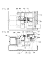
- Figs. 1A and 1B are diagrams illustrating behavior of ink.
- Fig. 2 is a perspective diagram illustrating an internal configuration of a printing apparatus according to an exemplary embodiment of the present invention.
- Fig. 3 is a perspective diagram illustrating a carrier portion and an ink supply mechanism of the printing apparatus according to the exemplary embodiment of the present invention.
- Figs. 4A and 4B are perspective and sectional diagrams illustrating a negative pressure valve according to the exemplary embodiment of the present invention.
- Figs. 5A and 5B are perspective and partially sectional diagrams illustrating a carrier according to the exemplary embodiment of the present invention.
- Figs. 6A and 6B are plan and partial sectional diagrams illustrating the printing apparatus according to the exemplary embodiment of the present invention.
- Figs. 7A and 7B are plan and partial sectional diagrams illustrating the printing apparatus according to the exemplary embodiment of the present invention.
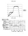
- Figs. 8A and 8B are graphs illustrating speed control and operation control according to the exemplary embodiment of the present invention.
- Fig. 9 is a perspective diagram illustrating an outer appearance of the printing apparatus according to the exemplary embodiment of the present invention.
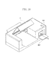
- Fig. 10 is a perspective diagram illustrating an outer appearance of the printing apparatus according to the exemplary embodiment of the present invention.
- Fig. 11 is a control block diagram of the printing apparatus according to the exemplary embodiment of the present invention.
- Figs. 9 and 10 are perspective diagrams each illustrating an outer appearance of a printing apparatus (recording apparatus) 1 according to an exemplary embodiment of the present invention.
- the printing apparatus 1 includes a casing cover 901, a maintenance cover 902, a guide 903 for supporting a print sheet 906, and a discharge port 904 for discharging the print sheet 906 which is a printed recording medium.
- the print sheet 906 is discharged in an arrow direction A.
- the printing apparatus 1 further includes a cover 907 for replacing an ink tank 101 that is replaceably installed in a casing to reserve a liquid.
- a cover 907 for replacing an ink tank 101 that is replaceably installed in a casing to reserve a liquid.
- the ink tank 101 is guided in an arrow direction D.
- the ink tank 101 is coupled with a supply port 307 ( Fig. 3 ).
- the printing device 1 includes a power switch 905.
- Fig. 2 is a perspective diagram illustrating an internal configuration of the printing apparatus 1.
- a chassis 201 supports the entire internal configuration.
- a platen 202 supports the print sheet 906.
- a roller 203 feeds the print sheet 906.
- a pinch roller 204 presses the print sheet 906 to the roller 203.
- the print sheet 906 is fed in the arrow direction A of Fig. 9 .
- a carrier 206 is supported to move reciprocally along a shaft 207 and a guide 205 in an arrow direction B.
- a motor 209 reciprocates the carrier 206 along the shaft 207 and the guide 205 in the arrow direction B via a belt 208 .
- a maintenance mechanism 210 is configured to maintain a printing mechanism mounted on the carrier 206.
- Fig. 3 is a perspective diagram illustrating a carrier portion of the printing apparatus 1 and an ink supply mechanism of a printing apparatus main-body side.
- Fig. 11 is a control block diagram of the printing apparatus 1.
- a main-body side supply mechanism 301 includes a mechanism of supplying inks as fluids or liquids to the carrier 206 from the outside.
- the main-body side supply mechanism 301 is supported by a shaft 302 and a guide 303 supported on the chassis 201 to move reciprocally in an arrow direction C perpendicular to the moving direction B of the carrier 206.
- a pump 304 serves as a pressure reducing unit for generating negative pressure to form an ink flow.
- the negative pressure is connected through a tube 305 and a negative pressure connection unit 306 to the main-body side supply mechanism 301.
- a supply port 307 is connected with the ink tank 101. By pushing-in the ink tank 101 toward the casing cover 901, the ink tank 101 is coupled with the supply port 307 so that no ink leakage will occur.
- the supply port 307 is connected through a tube 308 and a negative pressure valve 309 to the main-body side supply mechanism 301.
- a sub-ink tank 310 serves as a liquid chamber on the carrier 206 side. Negative pressure valves 311 and 312 are attached to the sub-ink tank 310.
- a rotation driving device 313 moves reciprocally the main-body side supply mechanism 301 in the arrow direction C and drives the pump 304.
- a driving direction of the pump 304 is not limited to a rotational direction of the rotation driving device 313, and the main-body side supply mechanism 301 side is configured to transmit driving force only in one direction by a one-way clutch (not shown).
- connection cam 316 is driven and rotated by the rotation driving device 313.
- a cam surface of the connection cam 316 abuts on a side face 301a of the main-body side supply mechanism 301, and rotates to move the main-body side supply mechanism 301 closer to the carrier 206.
- the negative pressure valve 309 and a part of the negative pressure connection unit 306 are moved to a position where they abut on a backside 206a of the carrier 206.
- connection cam 316 When a small-diameter part of the connection cam 316 rotates up to an initial position where the small-diameter part abuts on the side face 301a, the main-body side supply mechanism 301 is moved away from the carrier 206 under a spring force, and the negative pressure valve 309 and the negative pressure connection unit 306 are separated from the backside 206a of the carrier 206.
- the connection cam 316 and the spring constitute a moving unit.
- a disk 314 rotating integrally with the connection cam 316 includes a notch formed in a predetermined position. The notch is detected by a position sensor 315 to control a rotational angle phase of the connection cam 316.
- the rotation driving device 313 and the position sensor 315 are connected to a control circuit 700 ( Fig. 11 ) via wiring lines (not shown) to be controlled by the circuit 700.
- Figs. 4A and 4B are perspective and sectional diagrams of the negative pressure connection unit 306 and the negative pressure valve 309.
- the configuration includes a cylinder 401, a sealing member 404 made of an elastic material, and a spherical valve 402.
- the spherical valve 402 is biased to abut on a slope surface within the cylinder 401 by a spring 403 and holds a pressure difference between a communication port 401a side bored in the cylinder 401 and a communication port 404a side bored in the sealing member 404 side with a contact surface.
- the negative pressure connection unit 306 does not include the spherical valve 402 and the spring 403 but includes only the cylinder 401 and the sealing member 404.
- the pressure difference shows a relation, communication port 401a side pressure > sealing member 404 side pressure, and is determined by setting of the spring 403.
- the pressure difference exceeds the retaining force of the spring 403
- the spherical valve 402 moves away from the slope surface in the cylinder 401 so that the communication port 401a side is communicated with the sealing member 404 side.
- Figs. 5A and 5B are perspective and partial sectional diagrams illustrating the carrier 206.
- the carrier 206 is guided to move reciprocally by bearings 502 and 503 guided by the shaft 207 and the guide 205 of the chassis 201.
- An inkjet printing mechanism 504 is provided with an array of minute nozzles and includes an energy generating element for generating discharge pressure corresponding to each nozzle.
- the energy generating element is controlled to discharge ink from the corresponding nozzle based on a control signal sent from the control circuit 700 via a wiring line (not shown) .
- the carrier 206 includes a negative pressure port 505, an ink supply port 506, and holes 507 and 508 for adjusting a position with positioning bosses 317 and 318 of the main-body side supply mechanism 301.
- a negative pressure valve 509 controls a flow rate of an ink from a sub-tank 310 into an ink buffer chamber 510 of the inkjet printing mechanism 504 and is connected to the ink buffer chamber 510 through the communication port 511.
- a configuration of the negative pressure valves 309, 311, 312, and 509 is similar to that of Figs. 4A and 4B and their characteristics can be changed by a spring.
- Figs. 6A and 6B are plan and partial sectional diagrams of the printing apparatus 1.
- FIG. 6A and 6B illustrates the carrier 206 that reciprocates in the arrow direction B of Fig. 2 , and the inkjet printing mechanism 504 performs printing on the print sheet 906.
- a spherical valve 312a of the negative pressure valve 312 opens to cause an atmosphere to flow in.
- a spring 312b of the negative pressure valve 312 closes the spherical valve 312a.
- the negative pressure is maintained in the sub-tank 310 and no ink leakage occurs.
- the negative pressure valve 311 is not opened by the negative pressure on the sub-tank 310 side. Accordingly, no ink leakage occurs from this valve.
- Figs. 7A and 7B are plan and partial sectional diagrams of the printing apparatus 1.
- Each of Figs. 7A and 7B illustrates the negative pressure connection unit 306 and the negative pressure valve 309 that abut on the backside 206a of the carrier 206 to respectively connect to the negative pressure port 505 and the ink supply port 506.
- the main-body side supply mechanism 301 is moved to the carrier 206 side by rotation of the connection cam 316.
- the positioning bosses 317 and 318 of the main-body side supply mechanism 301 are engaged with the positioning holes 507 and 508 to position the main-body side supply mechanism 301 and the carrier 206 relative to each other.
- the negative pressure connection unit 306 and the negative pressure valve 309 respectively connect to the negative pressure port 505 and the ink supply port 506.
- the ink supply port 506 may be moved to connect to the negative pressure valve 309.
- the pump 304 is operated to generate negative pressure that is higher than presumed negative pressure in the sub-tank 310, and applies negative pressure to the negative pressure valve 311 via the negative pressure connection unit 306. Because of this negative pressure, a spring 311b of the negative pressure valve 311 loses out to negative pressure of the negative pressure connection unit 306 side so that a spherical valve 311a is opened, thereby increasing negative pressure in the sub-tank 310.
- the negative pressure of the sub-tank 310 When the negative pressure of the sub-tank 310 is increased, the negative pressure causes a spherical valve 312a of the negative pressure valve 312 to compress a spring 312b to make an opening. That is, the negative pressure valve 312 is opened because pressure of an opposite side is smaller than the ink supply port 506 side of the negative pressure valve 312 by a predetermined or more than a predetermined amount. Further, negative pressure applied from the opened negative pressure valve 312 causes a spherical valve 309a of the negative pressure valve 309 to compress a spring 309b to make an opening. That is, the negative pressure valve 309 is opened because pressure of an opposite side is larger than an opening 404d side of the negative pressure valve 309 by a predetermined or more than a predetermined amount. As a result, the ink tank 101 is connected to the sub-tank 310 in the negative pressure state, and ink flows from the ink tank 101 into the sub-tank 310.
- the negative pressure valve 509 serves as a check valve that prevents reverse flowing of the ink or flowing-in of air from the nozzles of the inkjet printing mechanism 504.
- a path of fluids from the supply port 307 connected to the ink tank 101 through the tube 308 to the negative pressure valve 309 corresponds to a first flow path.
- a path of fluids from the ink supply port 506 through the negative pressure valve 312 to the sub-tank 310 corresponds to a second flow path.
- the negative pressure of the sub-tank 310 opens the negative pressure valves 312 and 309 to cause the first and second flow paths to communicate with each other.
- the connection cam 316 and the pump 304 constitute a flow path connecting device.
- the connection cam 316 interconnects or separates the negative pressure valve 309 at the end of the first flow path and the supply port 307 at the end of the second flow path from each other.
- the pump 304 opens the negative pressure valves 312 and 309 to cause the first and second flow paths to communicate with each other.
- the main-body side supply mechanism 301 is separated from the carrier 206 side by rotation of the connection cam 316 to move to positions illustrated in Figs. 6A and 6B .
- a phenomenon of ink scattering is observed when the sealing member 404 of the negative pressure valve 309 is separated from the backside 206a of the carrier 206 during a separation operation of the main-body side supply mechanism 301 from the carrier 206. As the ink flows through the negative pressure valve 309, the ink remains around the communication port 404a and scatters in association with the separation operation. A space of a predetermined volume is present between the opening 404d of the sealing member 404 of the negative pressure valve 309 and the ink supply port 506 of the backside 206a of the carrier 206 and the ink scatters to the space during the separation.
- the scattered ink contaminates the print sheet 906. Moreover, an operation of each unit becomes unstable if the scattered ink is fixed.
- the inventors have found out by experiment that almost no ink scattering occurs if the relative speed of the negative pressure valve 309 and the backside 206a of the carrier 206 is equal to or less than a predetermined speed at the time that the valve 309 and the carrier 206 are separated.
- the inventors have also found out that the speed needs to be equal to or less than the above relative speed only within a predetermined distance from an abutting position and the speed can be increased without problems outside the predetermined distance.
- Figs. 1A and 1B illustrate the ink behavior when the sealing member 404 of the negative pressure valve 309 is separated from the abutting backside 206a of the carrier 206.
- Fig. 1A illustrating a case in which a separation speed is 20 mm/second or less
- Fig. 1B illustrating a case in which a separation speed is higher than 20 mm/second.
- the ink left around the communication port 404a side is collected in the lower side of the sealing member 404 under the influence of gravity.
- the ink collected in the lower side of the sealing member 404 is pulled to both sides while forming a bridge 601 between the sealing member 404 and the backside 206a of the carrier 206.
- the bridge is cut off, almost all of the ink is sucked by either side and thus little ink scattering occurs.
- the ink collected in the lower side of the sealing member 404 is also pulled to both sides while forming a bridge between the sealing member 404 and the backside 206a of the carrier 206.
- a bridge cutoff state is unstable, and ink droplets 602 which are not sucked to neither side are left and scatter.
- the inventors have confirmed that the ink bridge is cut off when a distance (separation distance) between the sealing member 404 and the backside 206a of the carrier 206 is approximately 4 mm according to the exemplary embodiment.
- Figs. 8A and 8B illustrate an example of speed control devised based on the experiment results. According to the illustrated example, the speed control is performed to prevent scattering of ink droplets when the negative pressure valve 309 is separated from the backside 206a of the carrier 206.
- Fig. 8A is a graph illustrating the relation between separation distance and speed.
- the moving speed of the negative pressure valve 309 is controlled to be 20 mm/second or less.
- the separation distance exceeds approximately 4 mm, no ink scatters. Accordingly, the negative pressure valve 309 can be moved at a speed higher than 20 mm/seconds. According to the exemplary embodiment, the speed is accelerated up to 50 mm/second.
- the speed of the negative pressure valve 309 is increased to 20 mm/second before a separation distance reaches 4 mm.
- the negative pressure valve 309 is moved at a constant speed of 20 mm/second until the separation distance reaches 4 mm.
- the speed is increased to 50 mm/second.
- the speed of the negative pressure valve 309 is increased under constant acceleration so that the speed reaches 20 mm/second when the separation distance reaches approximately 4 mm.
- the speed is increased up to 50 mm/second under higher acceleration. No ink scattering was observed when control was performed at both the speeds 1 and 2.
- the ink examined according to the exemplary embodiment has a normal viscosity of 3.3 (mPa/S) at a normal temperature and surface tension of 31 (mN/m). In a low-temperature environment, the viscosity and the surface tension increase by 1.5 times. However, no change occurred in separation conditions. Thus, similar effects can be achieved in fluids whose viscosity is 4 mPa/seconds or less. Similar effects can also be achieved in fluids whose surface tension is 40 mN/m or less.
- the sealing member 404 has a diameter of 5.5 mm as normal. However, due to variations of the components of the device, no change in separation conditions was observed up to about 6 mm. Accordingly, similar effects can be achieved if a diameter of a sealing surface of the sealing member 404 is 6 mm or less.
- the exemplary embodiment has been described in term of one color.
- the exemplary embodiment can also be applied to multiple colors without any problems. In that case, however, when a diameter of the sealing member 404 exceeds approximately 6 mm, the size of the carrier may have to increase.
- Fig. 8B is a chart collectively illustrating operations of each element with respect to a rotational angle of the connection cam 316. The operations of the exemplary embodiment are completed by one rotation of the connection cam 316.
- Fig. 8B when an ink supply operation is started, the control circuit 700 rotates the connection cam 316 by the rotation driving device 313.
- the connection cam 316 forms a rotational angle of 10°, a signal of the position sensor 315 is switched from a low level (L) to a high level (H).
- L low level
- H high level
- the connection cam 316 starts movement of the main-body side supply mechanism 301.
- the negative pressure connection unit 306 and the negative pressure valve 309 are respectively connected to the negative pressure port 505 and the ink supply port 506, and the main-body side supply mechanism 301 stops.
- the control circuit 700 drives the pump 304 by the rotation driving device 313 to supply the ink from the ink tank 101 to the sub-tank 310.
- the pump 304 is stopped and the ink supplying is finished.
- the connection cam 316 separates the main-body side supply mechanism 301 from the carrier 206.
- the main-body side supply mechanism 301 moves at a speed of 20 mm/seconds.
- connection cam 316 When the connection cam 316 forms a rotational angle of 300°, a distance (separation distance) between the sealing member 404 and the backside 206a of the carrier 206 is 4 mm. Between rotational angles of 300° and 340° after the predetermined period lapses, the main-body side supply mechanism 301 moves at a speed of 50 mm/seconds. At a rotational angle of 350°, the signal of the position sensor 315 is switched from H to L. The control circuit 700 controls the rotation driving device 313 to stop the connection cam 316 in response to the signal of the position sensor 315.
- the moving speed of the main-body side supply mechanism 301 is controlled based on the shape of the cam.
- the main-body side supply mechanism 301 may be driven and moved by the motor and the moving speed may be controlled by regulating a rotational speed of the motor. That is, during a predetermined period until a distance (separation distance) between the sealing member 404 and the backside 206a of the carrier 206 becomes 4 mm, the motor is driven at a first rotational speed. After a lapse of the predetermined period, the motor is driven at a second rotational speed that is higher than the first rotational speed.
Landscapes
- Ink Jet (AREA)
Abstract

Description
- The present invention relates to a flow path connecting device for automatically interconnecting flow paths of liquids to communicate with each other or for separating the flow paths from each other, or to a recording apparatus for supplying inks from the outside of a carrier including the flow path connecting device.
- A recent printing apparatus for a business purpose is expected to reduce the number of replacing times and running costs, so that a large capacity is required of an ink tank that contains a printing ink.
- An apparatus that performs printing by moving a carrier having a printing mechanism in a direction perpendicular to a printing sheet feeding direction generally mounts an ink tank on the carrier.
- However, this method has disadvantages, for example, if size of the carrier or weight of the ink tank is increased the speed of the carrier will decrease, or the size of a carrier motor must be increased to compensate for the reduction in speed. To solve such a problem, the ink tank can be arranged separately from the carrier, and the carrier printing mechanism and the ink tank can be interconnected through a tube.
- In such a tube connection method, the length of the tube needs to be set in anticipation of carrier movement. This method also has problems such as a detrimental influence of tube rigidity on the carrier movement, incursion of air into the ink from the outside of the tube, and evaporation of ink water to the outside of the tube, which makes it difficult to select a tube material.
- As an example of a solution to the aforementioned problems, an ink supply mechanism is discussed in Japanese Patent Application Laid-Open No.
2002-113879 - However, in the case of the supply mechanism and the operation discussed in Japanese Patent Application Laid-Open No.
2002-113879 - The present invention is directed to a mechanism for preventing or reduce the scattering of the ink from such a connection portion.
- The present invention in its first aspect provides a flow path connecting device for preventing scattering of ink as specified in claims 1 to 13.
- According to an exemplary embodiment of the present invention, scattering of fluids caused when the first connector of the first flow path and the second connector of the second flow path are separated from a connected state can be reduced.
- Further features and aspects of the present invention will become apparent from the following detailed description of exemplary embodiments with reference to the attached drawings.
- The accompanying drawings, which are incorporated in and constitute a part of the specification, illustrate exemplary embodiments, features, and aspects of the invention and, together with the description, serve to explain the principles of the invention.
-
Figs. 1A and 1B are diagrams illustrating behavior of ink. -
Fig. 2 is a perspective diagram illustrating an internal configuration of a printing apparatus according to an exemplary embodiment of the present invention. -
Fig. 3 is a perspective diagram illustrating a carrier portion and an ink supply mechanism of the printing apparatus according to the exemplary embodiment of the present invention. -
Figs. 4A and 4B are perspective and sectional diagrams illustrating a negative pressure valve according to the exemplary embodiment of the present invention. -
Figs. 5A and 5B are perspective and partially sectional diagrams illustrating a carrier according to the exemplary embodiment of the present invention. -
Figs. 6A and 6B are plan and partial sectional diagrams illustrating the printing apparatus according to the exemplary embodiment of the present invention. -
Figs. 7A and 7B are plan and partial sectional diagrams illustrating the printing apparatus according to the exemplary embodiment of the present invention. -
Figs. 8A and 8B are graphs illustrating speed control and operation control according to the exemplary embodiment of the present invention. -
Fig. 9 is a perspective diagram illustrating an outer appearance of the printing apparatus according to the exemplary embodiment of the present invention. -
Fig. 10 is a perspective diagram illustrating an outer appearance of the printing apparatus according to the exemplary embodiment of the present invention. -
Fig. 11 is a control block diagram of the printing apparatus according to the exemplary embodiment of the present invention. - Various exemplary embodiments, features, and aspects of the invention will now be described in detail with reference to the drawings.
-
Figs. 9 and10 are perspective diagrams each illustrating an outer appearance of a printing apparatus (recording apparatus) 1 according to an exemplary embodiment of the present invention. - The printing apparatus 1 includes a
casing cover 901, amaintenance cover 902, aguide 903 for supporting aprint sheet 906, and adischarge port 904 for discharging theprint sheet 906 which is a printed recording medium. Theprint sheet 906 is discharged in an arrow direction A. - The printing apparatus 1 further includes a
cover 907 for replacing anink tank 101 that is replaceably installed in a casing to reserve a liquid. In a state that thecover 907 is open as illustrated inFig. 10 , theink tank 101 is guided in an arrow direction D. When pushed into thecasing cover 901 side, theink tank 101 is coupled with a supply port 307 (Fig. 3 ). The printing device 1 includes apower switch 905. -
Fig. 2 is a perspective diagram illustrating an internal configuration of the printing apparatus 1. Achassis 201 supports the entire internal configuration. Aplaten 202 supports theprint sheet 906. Aroller 203 feeds theprint sheet 906. Apinch roller 204 presses theprint sheet 906 to theroller 203. By rotating theroller 203 by a driving device (not shown), theprint sheet 906 is fed in the arrow direction A ofFig. 9 . - A
carrier 206 is supported to move reciprocally along ashaft 207 and aguide 205 in an arrow direction B. Amotor 209 reciprocates thecarrier 206 along theshaft 207 and theguide 205 in the arrow direction B via abelt 208 . Amaintenance mechanism 210 is configured to maintain a printing mechanism mounted on thecarrier 206. -
Fig. 3 is a perspective diagram illustrating a carrier portion of the printing apparatus 1 and an ink supply mechanism of a printing apparatus main-body side.Fig. 11 is a control block diagram of the printing apparatus 1. - A main-body
side supply mechanism 301 includes a mechanism of supplying inks as fluids or liquids to thecarrier 206 from the outside. The main-bodyside supply mechanism 301 is supported by ashaft 302 and aguide 303 supported on thechassis 201 to move reciprocally in an arrow direction C perpendicular to the moving direction B of thecarrier 206. - A
pump 304 serves as a pressure reducing unit for generating negative pressure to form an ink flow. The negative pressure is connected through atube 305 and a negativepressure connection unit 306 to the main-bodyside supply mechanism 301. - A
supply port 307 is connected with theink tank 101. By pushing-in theink tank 101 toward thecasing cover 901, theink tank 101 is coupled with thesupply port 307 so that no ink leakage will occur. - The
supply port 307 is connected through atube 308 and anegative pressure valve 309 to the main-bodyside supply mechanism 301. Asub-ink tank 310 serves as a liquid chamber on thecarrier 206 side.Negative pressure valves sub-ink tank 310. - A
rotation driving device 313 moves reciprocally the main-bodyside supply mechanism 301 in the arrow direction C and drives thepump 304. A driving direction of thepump 304 is not limited to a rotational direction of therotation driving device 313, and the main-bodyside supply mechanism 301 side is configured to transmit driving force only in one direction by a one-way clutch (not shown). - A
connection cam 316 is driven and rotated by therotation driving device 313. A cam surface of theconnection cam 316 abuts on aside face 301a of the main-bodyside supply mechanism 301, and rotates to move the main-bodyside supply mechanism 301 closer to thecarrier 206. Then, thenegative pressure valve 309 and a part of the negativepressure connection unit 306 are moved to a position where they abut on abackside 206a of thecarrier 206. When a small-diameter part of theconnection cam 316 rotates up to an initial position where the small-diameter part abuts on theside face 301a, the main-bodyside supply mechanism 301 is moved away from thecarrier 206 under a spring force, and thenegative pressure valve 309 and the negativepressure connection unit 306 are separated from thebackside 206a of thecarrier 206. Theconnection cam 316 and the spring constitute a moving unit. Adisk 314 rotating integrally with theconnection cam 316 includes a notch formed in a predetermined position. The notch is detected by aposition sensor 315 to control a rotational angle phase of theconnection cam 316. - The
rotation driving device 313 and theposition sensor 315 are connected to a control circuit 700 (Fig. 11 ) via wiring lines (not shown) to be controlled by thecircuit 700. -
Figs. 4A and 4B are perspective and sectional diagrams of the negativepressure connection unit 306 and thenegative pressure valve 309. The configuration includes acylinder 401, a sealingmember 404 made of an elastic material, and aspherical valve 402. Thespherical valve 402 is biased to abut on a slope surface within thecylinder 401 by aspring 403 and holds a pressure difference between acommunication port 401a side bored in thecylinder 401 and acommunication port 404a side bored in the sealingmember 404 side with a contact surface. - However, the negative
pressure connection unit 306 does not include thespherical valve 402 and thespring 403 but includes only thecylinder 401 and the sealingmember 404. - The pressure difference shows a relation,
communication port 401a side pressure > sealingmember 404 side pressure, and is determined by setting of thespring 403. When the pressure difference exceeds the retaining force of thespring 403, thespherical valve 402 moves away from the slope surface in thecylinder 401 so that thecommunication port 401a side is communicated with the sealingmember 404 side. - When a sealing surface 404c of a
rib 404b of the sealingmember 404 abuts on abackside 206a of thecarrier 206, therib 404b deforms to provide an air-tight seal. -
Figs. 5A and 5B are perspective and partial sectional diagrams illustrating thecarrier 206. Thecarrier 206 is guided to move reciprocally bybearings shaft 207 and theguide 205 of thechassis 201. - An
inkjet printing mechanism 504 is provided with an array of minute nozzles and includes an energy generating element for generating discharge pressure corresponding to each nozzle. The energy generating element is controlled to discharge ink from the corresponding nozzle based on a control signal sent from thecontrol circuit 700 via a wiring line (not shown) . - The
carrier 206 includes anegative pressure port 505, anink supply port 506, and holes 507 and 508 for adjusting a position with positioningbosses side supply mechanism 301. - A
negative pressure valve 509 controls a flow rate of an ink from a sub-tank 310 into anink buffer chamber 510 of theinkjet printing mechanism 504 and is connected to theink buffer chamber 510 through thecommunication port 511. - A configuration of the
negative pressure valves Figs. 4A and 4B and their characteristics can be changed by a spring. -
Figs. 6A and 6B are plan and partial sectional diagrams of the printing apparatus 1. - Each of
Figs. 6A and 6B illustrates thecarrier 206 that reciprocates in the arrow direction B ofFig. 2 , and theinkjet printing mechanism 504 performs printing on theprint sheet 906. - When the
inkjet printing mechanism 504 consumes the ink in theink buffer chamber 510, pressure within theink buffer chamber 510 becomes negative. When the negative pressure reaches a certain value, aspherical valve 509a of thenegative pressure valve 509 compresses aspring 509b to make an opening, thereby supplying an ink from the sub-tank 310 into theink buffer chamber 510. - When the ink of the sub-tank 310 is reduced to produce negative pressure therein, and the negative pressure reaches a certain value, a
spherical valve 312a of thenegative pressure valve 312 opens to cause an atmosphere to flow in. When flowing-in of the atmosphere reaches a certain extent, aspring 312b of thenegative pressure valve 312 closes thespherical valve 312a. The negative pressure is maintained in the sub-tank 310 and no ink leakage occurs. Thenegative pressure valve 311 is not opened by the negative pressure on the sub-tank 310 side. Accordingly, no ink leakage occurs from this valve. -
Figs. 7A and 7B are plan and partial sectional diagrams of the printing apparatus 1. Each ofFigs. 7A and 7B illustrates the negativepressure connection unit 306 and thenegative pressure valve 309 that abut on thebackside 206a of thecarrier 206 to respectively connect to thenegative pressure port 505 and theink supply port 506. If thecarrier 206 is stopped in a predetermined position, the main-bodyside supply mechanism 301 is moved to thecarrier 206 side by rotation of theconnection cam 316. Thepositioning bosses side supply mechanism 301 are engaged with the positioning holes 507 and 508 to position the main-bodyside supply mechanism 301 and thecarrier 206 relative to each other. When the main-bodyside supply mechanism 301 is further moved, the negativepressure connection unit 306 and thenegative pressure valve 309 respectively connect to thenegative pressure port 505 and theink supply port 506. - Alternatively, the
ink supply port 506 may be moved to connect to thenegative pressure valve 309. - In this state, the
pump 304 is operated to generate negative pressure that is higher than presumed negative pressure in the sub-tank 310, and applies negative pressure to thenegative pressure valve 311 via the negativepressure connection unit 306. Because of this negative pressure, aspring 311b of thenegative pressure valve 311 loses out to negative pressure of the negativepressure connection unit 306 side so that aspherical valve 311a is opened, thereby increasing negative pressure in the sub-tank 310. - When the negative pressure of the sub-tank 310 is increased, the negative pressure causes a
spherical valve 312a of thenegative pressure valve 312 to compress aspring 312b to make an opening. That is, thenegative pressure valve 312 is opened because pressure of an opposite side is smaller than theink supply port 506 side of thenegative pressure valve 312 by a predetermined or more than a predetermined amount. Further, negative pressure applied from the openednegative pressure valve 312 causes aspherical valve 309a of thenegative pressure valve 309 to compress aspring 309b to make an opening. That is, thenegative pressure valve 309 is opened because pressure of an opposite side is larger than anopening 404d side of thenegative pressure valve 309 by a predetermined or more than a predetermined amount. As a result, theink tank 101 is connected to the sub-tank 310 in the negative pressure state, and ink flows from theink tank 101 into the sub-tank 310. - In this case, on the
inkjet printing mechanism 504 side, thenegative pressure valve 509 serves as a check valve that prevents reverse flowing of the ink or flowing-in of air from the nozzles of theinkjet printing mechanism 504. - According to the exemplary embodiment, a path of fluids from the
supply port 307 connected to theink tank 101 through thetube 308 to thenegative pressure valve 309 corresponds to a first flow path. A path of fluids from theink supply port 506 through thenegative pressure valve 312 to the sub-tank 310 corresponds to a second flow path. The negative pressure of the sub-tank 310 opens thenegative pressure valves connection cam 316 and thepump 304 constitute a flow path connecting device. Theconnection cam 316 interconnects or separates thenegative pressure valve 309 at the end of the first flow path and thesupply port 307 at the end of the second flow path from each other. Thepump 304 opens thenegative pressure valves - When the predetermined amount of ink is supplied to the sub-tank 310, the main-body
side supply mechanism 301 is separated from thecarrier 206 side by rotation of theconnection cam 316 to move to positions illustrated inFigs. 6A and 6B . - A phenomenon of ink scattering is observed when the sealing
member 404 of thenegative pressure valve 309 is separated from thebackside 206a of thecarrier 206 during a separation operation of the main-bodyside supply mechanism 301 from thecarrier 206. As the ink flows through thenegative pressure valve 309, the ink remains around thecommunication port 404a and scatters in association with the separation operation. A space of a predetermined volume is present between theopening 404d of the sealingmember 404 of thenegative pressure valve 309 and theink supply port 506 of thebackside 206a of thecarrier 206 and the ink scatters to the space during the separation. - The scattered ink contaminates the
print sheet 906. Moreover, an operation of each unit becomes unstable if the scattered ink is fixed. - The inventors have found out by experiment that almost no ink scattering occurs if the relative speed of the
negative pressure valve 309 and thebackside 206a of thecarrier 206 is equal to or less than a predetermined speed at the time that thevalve 309 and thecarrier 206 are separated. - The inventors have also found out that the speed needs to be equal to or less than the above relative speed only within a predetermined distance from an abutting position and the speed can be increased without problems outside the predetermined distance.
-
Figs. 1A and 1B illustrate the ink behavior when the sealingmember 404 of thenegative pressure valve 309 is separated from the abuttingbackside 206a of thecarrier 206.Fig. 1A illustrating a case in which a separation speed is 20 mm/second or less andFig. 1B illustrating a case in which a separation speed is higher than 20 mm/second. - According to the exemplary embodiment, as connection is made in a horizontal direction, the ink left around the
communication port 404a side is collected in the lower side of the sealingmember 404 under the influence of gravity. - In the case of separation at the speed of 20 mm/second and less, the ink collected in the lower side of the sealing
member 404 is pulled to both sides while forming abridge 601 between the sealingmember 404 and thebackside 206a of thecarrier 206. When the bridge is cut off, almost all of the ink is sucked by either side and thus little ink scattering occurs. - In the case of separation at the speed higher than 20 mm/second, the ink collected in the lower side of the sealing
member 404 is also pulled to both sides while forming a bridge between the sealingmember 404 and thebackside 206a of thecarrier 206. However, in this case, since the separation speed is high, a bridge cutoff state is unstable, andink droplets 602 which are not sucked to neither side are left and scatter. - The inventors have confirmed that the ink bridge is cut off when a distance (separation distance) between the sealing
member 404 and thebackside 206a of thecarrier 206 is approximately 4 mm according to the exemplary embodiment. -
Figs. 8A and 8B illustrate an example of speed control devised based on the experiment results. According to the illustrated example, the speed control is performed to prevent scattering of ink droplets when thenegative pressure valve 309 is separated from thebackside 206a of thecarrier 206.Fig. 8A is a graph illustrating the relation between separation distance and speed. - When the separation distance is approximately 4 mm or less after the separation starts, the moving speed of the
negative pressure valve 309 is controlled to be 20 mm/second or less. When the separation distance exceeds approximately 4 mm, no ink scatters. Accordingly, thenegative pressure valve 309 can be moved at a speed higher than 20 mm/seconds. According to the exemplary embodiment, the speed is accelerated up to 50 mm/second. - In the graph labeled speed 1 in
Fig. 8A , the speed of thenegative pressure valve 309 is increased to 20 mm/second before a separation distance reaches 4 mm. Thenegative pressure valve 309 is moved at a constant speed of 20 mm/second until the separation distance reaches 4 mm. When the separation distance exceeds 4 mm, the speed is increased to 50 mm/second. - In the graph of a
speed 2, the speed of thenegative pressure valve 309 is increased under constant acceleration so that the speed reaches 20 mm/second when the separation distance reaches approximately 4 mm. When the separation speed exceeds 4 mm, the speed is increased up to 50 mm/second under higher acceleration. No ink scattering was observed when control was performed at both thespeeds 1 and 2. - The ink examined according to the exemplary embodiment has a normal viscosity of 3.3 (mPa/S) at a normal temperature and surface tension of 31 (mN/m). In a low-temperature environment, the viscosity and the surface tension increase by 1.5 times. However, no change occurred in separation conditions. Thus, similar effects can be achieved in fluids whose viscosity is 4 mPa/seconds or less. Similar effects can also be achieved in fluids whose surface tension is 40 mN/m or less.
- The sealing
member 404 has a diameter of 5.5 mm as normal. However, due to variations of the components of the device, no change in separation conditions was observed up to about 6 mm. Accordingly, similar effects can be achieved if a diameter of a sealing surface of the sealingmember 404 is 6 mm or less. - For the sake of brevity, the exemplary embodiment has been described in term of one color. The exemplary embodiment can also be applied to multiple colors without any problems. In that case, however, when a diameter of the sealing
member 404 exceeds approximately 6 mm, the size of the carrier may have to increase. -
Fig. 8B is a chart collectively illustrating operations of each element with respect to a rotational angle of theconnection cam 316. The operations of the exemplary embodiment are completed by one rotation of theconnection cam 316. - In
Fig. 8B , when an ink supply operation is started, thecontrol circuit 700 rotates theconnection cam 316 by therotation driving device 313. When theconnection cam 316 forms a rotational angle of 10°, a signal of theposition sensor 315 is switched from a low level (L) to a high level (H). At a rotational angle of 20°, theconnection cam 316 starts movement of the main-bodyside supply mechanism 301. At a rotational angle of 70°, as illustrated inFigs. 7A and 7B , the negativepressure connection unit 306 and thenegative pressure valve 309 are respectively connected to thenegative pressure port 505 and theink supply port 506, and the main-bodyside supply mechanism 301 stops. At a rotational angle of 90°, thecontrol circuit 700 drives thepump 304 by therotation driving device 313 to supply the ink from theink tank 101 to the sub-tank 310. At a rotational angle of 220°, thepump 304 is stopped and the ink supplying is finished. From a rotational angle of 240°, theconnection cam 316 separates the main-bodyside supply mechanism 301 from thecarrier 206. During a predetermined period from rotational angles of 240° to 300° of theconnection cam 316, the main-bodyside supply mechanism 301 moves at a speed of 20 mm/seconds. When theconnection cam 316 forms a rotational angle of 300°, a distance (separation distance) between the sealingmember 404 and thebackside 206a of thecarrier 206 is 4 mm. Between rotational angles of 300° and 340° after the predetermined period lapses, the main-bodyside supply mechanism 301 moves at a speed of 50 mm/seconds. At a rotational angle of 350°, the signal of theposition sensor 315 is switched from H to L. Thecontrol circuit 700 controls therotation driving device 313 to stop theconnection cam 316 in response to the signal of theposition sensor 315. - According to the exemplary embodiment, the moving speed of the main-body
side supply mechanism 301 is controlled based on the shape of the cam. However, the main-bodyside supply mechanism 301 may be driven and moved by the motor and the moving speed may be controlled by regulating a rotational speed of the motor. That is, during a predetermined period until a distance (separation distance) between the sealingmember 404 and thebackside 206a of thecarrier 206 becomes 4 mm, the motor is driven at a first rotational speed. After a lapse of the predetermined period, the motor is driven at a second rotational speed that is higher than the first rotational speed. - While the present invention has been described with reference to exemplary embodiments, it is to be understood that the invention is not limited to the disclosed exemplary embodiments. The scope of the following claims is to be accorded the broadest interpretation so as to encompass all modifications, equivalent structures, and functions.
Claims (15)
- A flow path connecting device comprising:a first flow path having a first connector (309) and configured to channel fluids;a second flow path having a second connector (312) and configured to channel fluids;moving means operable to move at least one of the first and second connectors (309, 312), to interconnect the first and second connectors (309, 312) so that the first and second flow paths communicate with each other, and operable to move at least one of the first and second connectors (309, 312) to separate the first and second connectors (309, 312) from each other; andcontrol means (700) configured to control the moving means, when the first and second connectors (309, 312) separate from each other, to set a relative speed of the first and second connectors (309, 312) to a first speed or less in a period from a start of the separation till a predetermined time expires, and to set the relative speed to a second speed that is higher than the first speed after the predetermined time expires.
- The flow path connecting device according to claim 1, wherein the first connector (309) includes a first surface having a first opening which is an end of the first flow path, the second connector (312) includes a second surface having a second opening which is an end of the second flow path, and the moving unit causes the first and second surfaces to abut on each other so that the first and second flow paths communicate with each other.
- The flow path connecting device according to claim 2, wherein the first surface is a sealing surface.
- The flow path connecting device according to any preceding claim, wherein the first connector (309) includes a first valve for closing the first flow path, the second connector (312) includes a second valve (312a) for closing the second flow path and, when the first and second connectors (309, 312) are separated from each other, the first and second valves are closed.
- The flow path connecting device according to claim 4, wherein the first flow path includes a predetermined inner volume between the first valve and the first opening.
- The flow path connecting device according to claim 4 or 5, wherein the second valve (312a) is opened when pressure at a side opposite to the second opening is smaller than pressure of the second opening side by a value equal to or larger than a predetermined value.
- The flow path connecting device according to claim 6, wherein the first valve is opened when pressure at a side opposite to the first opening is larger than pressure of the first opening side by a value equal to or larger than a predetermined value.
- The flow path connecting device according to any preceding claim, wherein the first speed is 20 mm/second.
- The flow path connecting device according to any preceding claim, wherein the predetermined time is the time to separate the first and second connectors (309, 312) from each other by 4 mm.
- The flow path connecting device according to any preceding claim, wherein the first and second flow paths are configured to channel a liquid.
- The flow path connecting device as claimed in claim 10 in which the first and second flow paths are configured to channel a liquid having a surface tension of 40 mN/m or less.
- The flow path connecting device according to claim 10, wherein the first and second flow paths are configured to channel a liquid having a viscosity of 4 mPa/seconds or less.
- The flow path connecting device according to claim 3, wherein a diameter of the sealing surface is 6 mm or less.
- A recording apparatus comprising:a nozzle configured to discharge a liquid for recording in a recording medium;a liquid chamber configured to store the liquid supplied to the nozzle;a tank configured to store the liquid supplied to the liquid chamber; anda flow path connecting device as claimed in any preceding claim.
- The recording apparatus according to claim 14, further comprising pressure reducing means configured to reduce pressure in the liquid chamber,
wherein the control means (700) is operable to control the moving means and the pressure reducing means such that the first and second connectors (309, 312) are brought into communication with each other by the moving means, and such that the pressure of the liquid chamber is reduced by the pressure reducing means to open the first and second valves, and such that the liquid stored in the tank is supplied to the liquid chamber owing to a pressure difference between the liquid chamber and the tank.
Applications Claiming Priority (1)
| Application Number | Priority Date | Filing Date | Title |
|---|---|---|---|
| JP2007175294A JP2009012255A (en) | 2007-07-03 | 2007-07-03 | Flow path connecting apparatus and recording apparatus |
Publications (1)
| Publication Number | Publication Date |
|---|---|
| EP2011658A1 true EP2011658A1 (en) | 2009-01-07 |
Family
ID=39898698
Family Applications (1)
| Application Number | Title | Priority Date | Filing Date |
|---|---|---|---|
| EP08159207A Withdrawn EP2011658A1 (en) | 2007-07-03 | 2008-06-27 | Flow path connecting device and recording apparatus |
Country Status (4)
| Country | Link |
|---|---|
| US (1) | US7850292B2 (en) |
| EP (1) | EP2011658A1 (en) |
| JP (1) | JP2009012255A (en) |
| CN (1) | CN101337467A (en) |
Families Citing this family (2)
| Publication number | Priority date | Publication date | Assignee | Title |
|---|---|---|---|---|
| JP2010228149A (en) * | 2009-03-26 | 2010-10-14 | Seiko Epson Corp | Fluid supply device, fluid ejection device, and fluid supply method |
| US10632758B2 (en) | 2017-07-07 | 2020-04-28 | Canon Kabushiki Kaisha | Inkjet printing apparatus and control method of the same |
Citations (2)
| Publication number | Priority date | Publication date | Assignee | Title |
|---|---|---|---|---|
| US6099112A (en) * | 1997-03-03 | 2000-08-08 | Hewlett-Packard Company | Carriage stabilization during periodic valve engagement for printhead replenishment |
| JP2002113879A (en) | 2000-10-06 | 2002-04-16 | Fuji Xerox Co Ltd | Ink replenishment device and ink jet recorder |
Family Cites Families (3)
| Publication number | Priority date | Publication date | Assignee | Title |
|---|---|---|---|---|
| US6224198B1 (en) * | 1999-04-13 | 2001-05-01 | Lexmark International, Inc. | Method and apparatus for refilling ink jet cartridges with minimum ink loss |
| JP2002234180A (en) * | 2001-02-09 | 2002-08-20 | Canon Inc | Ink supply device, ink supply mechanism, and inkjet recording device |
| JP2004034336A (en) | 2002-06-28 | 2004-02-05 | Fuji Xerox Co Ltd | Ink supply unit, subink tank and inkjet recorder |
-
2007
- 2007-07-03 JP JP2007175294A patent/JP2009012255A/en active Pending
-
2008
- 2008-06-24 US US12/145,431 patent/US7850292B2/en not_active Expired - Fee Related
- 2008-06-27 EP EP08159207A patent/EP2011658A1/en not_active Withdrawn
- 2008-07-03 CN CNA2008101359073A patent/CN101337467A/en active Pending
Patent Citations (2)
| Publication number | Priority date | Publication date | Assignee | Title |
|---|---|---|---|---|
| US6099112A (en) * | 1997-03-03 | 2000-08-08 | Hewlett-Packard Company | Carriage stabilization during periodic valve engagement for printhead replenishment |
| JP2002113879A (en) | 2000-10-06 | 2002-04-16 | Fuji Xerox Co Ltd | Ink replenishment device and ink jet recorder |
Also Published As
| Publication number | Publication date |
|---|---|
| CN101337467A (en) | 2009-01-07 |
| JP2009012255A (en) | 2009-01-22 |
| US20090009568A1 (en) | 2009-01-08 |
| US7850292B2 (en) | 2010-12-14 |
Similar Documents
| Publication | Publication Date | Title |
|---|---|---|
| US6481837B1 (en) | Ink delivery system | |
| JP5789999B2 (en) | Liquid ejector | |
| US8602513B2 (en) | Inkjet printing apparatus | |
| US8480216B2 (en) | Liquid ejecting apparatus | |
| US9358794B2 (en) | Liquid ejecting apparatus | |
| JP6763289B2 (en) | Liquid injection device and maintenance method of liquid injection device | |
| EP2070704A1 (en) | Liquid supply device and liquid ejecting apparatus | |
| CN101676111A (en) | Fluid supply device, printing device, and method of controlling a fluid supply device | |
| US20190275804A1 (en) | Ink supply system and ink jet printer | |
| US20100245465A1 (en) | Liquid supplying apparatus and liquid ejecting apparatus | |
| JP2008238787A (en) | Liquid supply system, liquid supply apparatus, and liquid supply method | |
| US7850292B2 (en) | Flow path connecting device and recording apparatus | |
| JPH0834122A (en) | INKJET CARTRIDGE AND INKJET RECORDING DEVICE HAVING THE SAME | |
| CN104411499A (en) | Inkjet printing device, liquid supply device and print head cleaning method | |
| US7401889B2 (en) | Liquid ejector cleaning method and liquid ejector | |
| US7128390B2 (en) | Ink jet recording apparatus | |
| CN101456290A (en) | Liquid ejecting device, printing apparatus and liquid supplying method | |
| JP6156454B2 (en) | Liquid ejector | |
| JP6399156B2 (en) | Liquid storage unit and liquid ejecting apparatus | |
| US20180201013A1 (en) | Liquid ejecting apparatus | |
| US11724513B2 (en) | Liquid circulation mechanism, liquid circulation device, and liquid discharging apparatus | |
| US12454132B2 (en) | Liquid ejection apparatus and control method of liquid ejection apparatus | |
| JP2934016B2 (en) | Ink jet recording device | |
| JP2954038B2 (en) | Ink suction means | |
| JP6399154B2 (en) | Pressure adjusting unit, liquid ejecting unit, and liquid ejecting apparatus |
Legal Events
| Date | Code | Title | Description |
|---|---|---|---|
| PUAI | Public reference made under article 153(3) epc to a published international application that has entered the european phase |
Free format text: ORIGINAL CODE: 0009012 |
|
| AK | Designated contracting states |
Kind code of ref document: A1 Designated state(s): AT BE BG CH CY CZ DE DK EE ES FI FR GB GR HR HU IE IS IT LI LT LU LV MC MT NL NO PL PT RO SE SI SK TR |
|
| AX | Request for extension of the european patent |
Extension state: AL BA MK RS |
|
| 17P | Request for examination filed |
Effective date: 20090707 |
|
| AKX | Designation fees paid |
Designated state(s): DE FR GB IT |
|
| 17Q | First examination report despatched |
Effective date: 20090819 |
|
| STAA | Information on the status of an ep patent application or granted ep patent |
Free format text: STATUS: THE APPLICATION HAS BEEN WITHDRAWN |
|
| 18W | Application withdrawn |
Effective date: 20100111 |