EP2011551A1 - Exercise management system, exercise management method, and exercise management program - Google Patents
Exercise management system, exercise management method, and exercise management program Download PDFInfo
- Publication number
- EP2011551A1 EP2011551A1 EP07739632A EP07739632A EP2011551A1 EP 2011551 A1 EP2011551 A1 EP 2011551A1 EP 07739632 A EP07739632 A EP 07739632A EP 07739632 A EP07739632 A EP 07739632A EP 2011551 A1 EP2011551 A1 EP 2011551A1
- Authority
- EP
- European Patent Office
- Prior art keywords
- motion
- animal
- variable
- oscillator
- walking
- Prior art date
- Legal status (The legal status is an assumption and is not a legal conclusion. Google has not performed a legal analysis and makes no representation as to the accuracy of the status listed.)
- Granted
Links
Images




Classifications
-
- A—HUMAN NECESSITIES
- A63—SPORTS; GAMES; AMUSEMENTS
- A63B—APPARATUS FOR PHYSICAL TRAINING, GYMNASTICS, SWIMMING, CLIMBING, OR FENCING; BALL GAMES; TRAINING EQUIPMENT
- A63B21/00—Exercising apparatus for developing or strengthening the muscles or joints of the body by working against a counterforce, with or without measuring devices
- A63B21/00181—Exercising apparatus for developing or strengthening the muscles or joints of the body by working against a counterforce, with or without measuring devices comprising additional means assisting the user to overcome part of the resisting force, i.e. assisted-active exercising
-
- A—HUMAN NECESSITIES
- A61—MEDICAL OR VETERINARY SCIENCE; HYGIENE
- A61B—DIAGNOSIS; SURGERY; IDENTIFICATION
- A61B5/00—Measuring for diagnostic purposes; Identification of persons
- A61B5/02—Detecting, measuring or recording for evaluating the cardiovascular system, e.g. pulse, heart rate, blood pressure or blood flow
- A61B5/024—Measuring pulse rate or heart rate
- A61B5/02438—Measuring pulse rate or heart rate with portable devices, e.g. worn by the patient
-
- A—HUMAN NECESSITIES
- A61—MEDICAL OR VETERINARY SCIENCE; HYGIENE
- A61B—DIAGNOSIS; SURGERY; IDENTIFICATION
- A61B5/00—Measuring for diagnostic purposes; Identification of persons
- A61B5/103—Measuring devices for testing the shape, pattern, colour, size or movement of the body or parts thereof, for diagnostic purposes
- A61B5/1036—Measuring load distribution, e.g. podologic studies
- A61B5/1038—Measuring plantar pressure during gait
-
- A—HUMAN NECESSITIES
- A61—MEDICAL OR VETERINARY SCIENCE; HYGIENE
- A61B—DIAGNOSIS; SURGERY; IDENTIFICATION
- A61B5/00—Measuring for diagnostic purposes; Identification of persons
- A61B5/103—Measuring devices for testing the shape, pattern, colour, size or movement of the body or parts thereof, for diagnostic purposes
- A61B5/11—Measuring movement of the entire body or parts thereof, e.g. head or hand tremor or mobility of a limb
- A61B5/112—Gait analysis
-
- A—HUMAN NECESSITIES
- A61—MEDICAL OR VETERINARY SCIENCE; HYGIENE
- A61B—DIAGNOSIS; SURGERY; IDENTIFICATION
- A61B5/00—Measuring for diagnostic purposes; Identification of persons
- A61B5/103—Measuring devices for testing the shape, pattern, colour, size or movement of the body or parts thereof, for diagnostic purposes
- A61B5/11—Measuring movement of the entire body or parts thereof, e.g. head or hand tremor or mobility of a limb
- A61B5/1124—Determining motor skills
-
- A—HUMAN NECESSITIES
- A61—MEDICAL OR VETERINARY SCIENCE; HYGIENE
- A61H—PHYSICAL THERAPY APPARATUS, e.g. DEVICES FOR LOCATING OR STIMULATING REFLEX POINTS IN THE BODY; ARTIFICIAL RESPIRATION; MASSAGE; BATHING DEVICES FOR SPECIAL THERAPEUTIC OR HYGIENIC PURPOSES OR SPECIFIC PARTS OF THE BODY
- A61H1/00—Apparatus for passive exercising; Vibrating apparatus; Chiropractic devices, e.g. body impacting devices, external devices for briefly extending or aligning unbroken bones
- A61H1/02—Stretching or bending or torsioning apparatus for exercising
-
- A—HUMAN NECESSITIES
- A61—MEDICAL OR VETERINARY SCIENCE; HYGIENE
- A61H—PHYSICAL THERAPY APPARATUS, e.g. DEVICES FOR LOCATING OR STIMULATING REFLEX POINTS IN THE BODY; ARTIFICIAL RESPIRATION; MASSAGE; BATHING DEVICES FOR SPECIAL THERAPEUTIC OR HYGIENIC PURPOSES OR SPECIFIC PARTS OF THE BODY
- A61H3/00—Appliances for aiding patients or disabled persons to walk about
-
- A—HUMAN NECESSITIES
- A63—SPORTS; GAMES; AMUSEMENTS
- A63B—APPARATUS FOR PHYSICAL TRAINING, GYMNASTICS, SWIMMING, CLIMBING, OR FENCING; BALL GAMES; TRAINING EQUIPMENT
- A63B21/00—Exercising apparatus for developing or strengthening the muscles or joints of the body by working against a counterforce, with or without measuring devices
- A63B21/40—Interfaces with the user related to strength training; Details thereof
- A63B21/4001—Arrangements for attaching the exercising apparatus to the user's body, e.g. belts, shoes or gloves specially adapted therefor
- A63B21/4011—Arrangements for attaching the exercising apparatus to the user's body, e.g. belts, shoes or gloves specially adapted therefor to the lower limbs
-
- A—HUMAN NECESSITIES
- A63—SPORTS; GAMES; AMUSEMENTS
- A63B—APPARATUS FOR PHYSICAL TRAINING, GYMNASTICS, SWIMMING, CLIMBING, OR FENCING; BALL GAMES; TRAINING EQUIPMENT
- A63B22/00—Exercising apparatus specially adapted for conditioning the cardio-vascular system, for training agility or co-ordination of movements
- A63B22/02—Exercising apparatus specially adapted for conditioning the cardio-vascular system, for training agility or co-ordination of movements with movable endless bands, e.g. treadmills
- A63B22/0235—Exercising apparatus specially adapted for conditioning the cardio-vascular system, for training agility or co-ordination of movements with movable endless bands, e.g. treadmills driven by a motor
-
- A—HUMAN NECESSITIES
- A63—SPORTS; GAMES; AMUSEMENTS
- A63B—APPARATUS FOR PHYSICAL TRAINING, GYMNASTICS, SWIMMING, CLIMBING, OR FENCING; BALL GAMES; TRAINING EQUIPMENT
- A63B69/00—Training appliances or apparatus for special sports
- A63B69/0028—Training appliances or apparatus for special sports for running, jogging or speed-walking
-
- A—HUMAN NECESSITIES
- A63—SPORTS; GAMES; AMUSEMENTS
- A63B—APPARATUS FOR PHYSICAL TRAINING, GYMNASTICS, SWIMMING, CLIMBING, OR FENCING; BALL GAMES; TRAINING EQUIPMENT
- A63B71/00—Games or sports accessories not covered in groups A63B1/00 - A63B69/00
- A63B71/06—Indicating or scoring devices for games or players, or for other sports activities
- A63B71/0686—Timers, rhythm indicators or pacing apparatus using electric or electronic means
-
- A—HUMAN NECESSITIES
- A61—MEDICAL OR VETERINARY SCIENCE; HYGIENE
- A61H—PHYSICAL THERAPY APPARATUS, e.g. DEVICES FOR LOCATING OR STIMULATING REFLEX POINTS IN THE BODY; ARTIFICIAL RESPIRATION; MASSAGE; BATHING DEVICES FOR SPECIAL THERAPEUTIC OR HYGIENIC PURPOSES OR SPECIFIC PARTS OF THE BODY
- A61H2201/00—Characteristics of apparatus not provided for in the preceding codes
- A61H2201/50—Control means thereof
- A61H2201/5007—Control means thereof computer controlled
-
- A—HUMAN NECESSITIES
- A61—MEDICAL OR VETERINARY SCIENCE; HYGIENE
- A61H—PHYSICAL THERAPY APPARATUS, e.g. DEVICES FOR LOCATING OR STIMULATING REFLEX POINTS IN THE BODY; ARTIFICIAL RESPIRATION; MASSAGE; BATHING DEVICES FOR SPECIAL THERAPEUTIC OR HYGIENIC PURPOSES OR SPECIFIC PARTS OF THE BODY
- A61H2201/00—Characteristics of apparatus not provided for in the preceding codes
- A61H2201/50—Control means thereof
- A61H2201/5058—Sensors or detectors
- A61H2201/5064—Position sensors
-
- A—HUMAN NECESSITIES
- A61—MEDICAL OR VETERINARY SCIENCE; HYGIENE
- A61H—PHYSICAL THERAPY APPARATUS, e.g. DEVICES FOR LOCATING OR STIMULATING REFLEX POINTS IN THE BODY; ARTIFICIAL RESPIRATION; MASSAGE; BATHING DEVICES FOR SPECIAL THERAPEUTIC OR HYGIENIC PURPOSES OR SPECIFIC PARTS OF THE BODY
- A61H2201/00—Characteristics of apparatus not provided for in the preceding codes
- A61H2201/50—Control means thereof
- A61H2201/5058—Sensors or detectors
- A61H2201/5069—Angle sensors
-
- A—HUMAN NECESSITIES
- A61—MEDICAL OR VETERINARY SCIENCE; HYGIENE
- A61H—PHYSICAL THERAPY APPARATUS, e.g. DEVICES FOR LOCATING OR STIMULATING REFLEX POINTS IN THE BODY; ARTIFICIAL RESPIRATION; MASSAGE; BATHING DEVICES FOR SPECIAL THERAPEUTIC OR HYGIENIC PURPOSES OR SPECIFIC PARTS OF THE BODY
- A61H2201/00—Characteristics of apparatus not provided for in the preceding codes
- A61H2201/50—Control means thereof
- A61H2201/5058—Sensors or detectors
- A61H2201/5079—Velocity sensors
-
- A—HUMAN NECESSITIES
- A63—SPORTS; GAMES; AMUSEMENTS
- A63B—APPARATUS FOR PHYSICAL TRAINING, GYMNASTICS, SWIMMING, CLIMBING, OR FENCING; BALL GAMES; TRAINING EQUIPMENT
- A63B2220/00—Measuring of physical parameters relating to sporting activity
- A63B2220/10—Positions
- A63B2220/16—Angular positions
-
- A—HUMAN NECESSITIES
- A63—SPORTS; GAMES; AMUSEMENTS
- A63B—APPARATUS FOR PHYSICAL TRAINING, GYMNASTICS, SWIMMING, CLIMBING, OR FENCING; BALL GAMES; TRAINING EQUIPMENT
- A63B2220/00—Measuring of physical parameters relating to sporting activity
- A63B2220/17—Counting, e.g. counting periodical movements, revolutions or cycles, or including further data processing to determine distances or speed
-
- A—HUMAN NECESSITIES
- A63—SPORTS; GAMES; AMUSEMENTS
- A63B—APPARATUS FOR PHYSICAL TRAINING, GYMNASTICS, SWIMMING, CLIMBING, OR FENCING; BALL GAMES; TRAINING EQUIPMENT
- A63B2220/00—Measuring of physical parameters relating to sporting activity
- A63B2220/30—Speed
-
- A—HUMAN NECESSITIES
- A63—SPORTS; GAMES; AMUSEMENTS
- A63B—APPARATUS FOR PHYSICAL TRAINING, GYMNASTICS, SWIMMING, CLIMBING, OR FENCING; BALL GAMES; TRAINING EQUIPMENT
- A63B2220/00—Measuring of physical parameters relating to sporting activity
- A63B2220/40—Acceleration
-
- A—HUMAN NECESSITIES
- A63—SPORTS; GAMES; AMUSEMENTS
- A63B—APPARATUS FOR PHYSICAL TRAINING, GYMNASTICS, SWIMMING, CLIMBING, OR FENCING; BALL GAMES; TRAINING EQUIPMENT
- A63B2220/00—Measuring of physical parameters relating to sporting activity
- A63B2220/50—Force related parameters
- A63B2220/56—Pressure
-
- A—HUMAN NECESSITIES
- A63—SPORTS; GAMES; AMUSEMENTS
- A63B—APPARATUS FOR PHYSICAL TRAINING, GYMNASTICS, SWIMMING, CLIMBING, OR FENCING; BALL GAMES; TRAINING EQUIPMENT
- A63B2220/00—Measuring of physical parameters relating to sporting activity
- A63B2220/80—Special sensors, transducers or devices therefor
- A63B2220/803—Motion sensors
-
- A—HUMAN NECESSITIES
- A63—SPORTS; GAMES; AMUSEMENTS
- A63B—APPARATUS FOR PHYSICAL TRAINING, GYMNASTICS, SWIMMING, CLIMBING, OR FENCING; BALL GAMES; TRAINING EQUIPMENT
- A63B2230/00—Measuring physiological parameters of the user
- A63B2230/04—Measuring physiological parameters of the user heartbeat characteristics, e.g. ECG, blood pressure modulations
- A63B2230/06—Measuring physiological parameters of the user heartbeat characteristics, e.g. ECG, blood pressure modulations heartbeat rate only
-
- A—HUMAN NECESSITIES
- A63—SPORTS; GAMES; AMUSEMENTS
- A63B—APPARATUS FOR PHYSICAL TRAINING, GYMNASTICS, SWIMMING, CLIMBING, OR FENCING; BALL GAMES; TRAINING EQUIPMENT
- A63B2230/00—Measuring physiological parameters of the user
- A63B2230/30—Measuring physiological parameters of the user blood pressure
-
- A—HUMAN NECESSITIES
- A63—SPORTS; GAMES; AMUSEMENTS
- A63B—APPARATUS FOR PHYSICAL TRAINING, GYMNASTICS, SWIMMING, CLIMBING, OR FENCING; BALL GAMES; TRAINING EQUIPMENT
- A63B2230/00—Measuring physiological parameters of the user
- A63B2230/40—Measuring physiological parameters of the user respiratory characteristics
- A63B2230/42—Measuring physiological parameters of the user respiratory characteristics rate
-
- A—HUMAN NECESSITIES
- A63—SPORTS; GAMES; AMUSEMENTS
- A63B—APPARATUS FOR PHYSICAL TRAINING, GYMNASTICS, SWIMMING, CLIMBING, OR FENCING; BALL GAMES; TRAINING EQUIPMENT
- A63B2230/00—Measuring physiological parameters of the user
- A63B2230/75—Measuring physiological parameters of the user calorie expenditure
-
- Y—GENERAL TAGGING OF NEW TECHNOLOGICAL DEVELOPMENTS; GENERAL TAGGING OF CROSS-SECTIONAL TECHNOLOGIES SPANNING OVER SEVERAL SECTIONS OF THE IPC; TECHNICAL SUBJECTS COVERED BY FORMER USPC CROSS-REFERENCE ART COLLECTIONS [XRACs] AND DIGESTS
- Y10—TECHNICAL SUBJECTS COVERED BY FORMER USPC
- Y10S—TECHNICAL SUBJECTS COVERED BY FORMER USPC CROSS-REFERENCE ART COLLECTIONS [XRACs] AND DIGESTS
- Y10S482/00—Exercise devices
- Y10S482/901—Exercise devices having computer circuitry
Definitions
- the present invention relates to a system and method for managing exercise of an animal, and a program for providing a computer with the management function.
- An exercise management system includes: a control unit which controls an operation of a second motion induction device inducing motion of the animal while adjusting a motion scale of the animal at a rhythm harmonized with a motion rhythm of the animal; a physiological variable measuring unit which measures a physiological variable representing a physiological condition of the animal; a motion variable measuring unit which measures a motion variable representing one or both of the motion scale and the motion rhythm of the animal; and a recommended value setting unit which sets, as a recommended value of the motion variable, the motion variable that is measured by the motion variable measuring unit at the time when the physiological variable measured by the physiological variable measuring unit in the state where the motion of the animal is induced by the operation of the second motion induction device that is controlled by the control unit to change the motion variable attains an appropriate value in consideration of activation of physical functions or reduction of body load of the animal.
- the physiological variable and motion variable of the animal are measured in the state where the motion of the animal is induced by the operation of the second motion induction device.
- the "physiological variable” represents the physiological condition of the animal.
- the “motion variable” represents one or both of the motion scale and motion rhythm of the animal.
- the value of the motion variable obtained at the time when the physiological variable attains an appropriate value in consideration of "activation of physical functions” or “reduction of body load” of the animal is set as the recommended value of the motion variable. This ensures that the recommended value of the motion variable of the animal is set as appropriate in consideration of activation of the physical functions of the animal or the like.
- the motion of the animal is then induced by the second motion induction device according to this recommended value, which allows the induction scale and the induction rhythm to be controlled appropriately so that the motion scale and the motion rhythm of the animal are appropriate in consideration of activation of the physical functions of the animal or the like.
- the motion of the animal can be induced with an appropriate scale and rhythm in consideration of activation of the physical functions or the like, in accordance with the physiological conditions of the animal.
- an exercise management system is characterized in that, in the exercise management system of the first invention, the control unit includes: a motion oscillator measuring unit which measures first and second motion oscillators as parameters that periodically change in accordance with the motion of the animal; a first oscillator generating unit which inputs the first motion oscillator measured by the motion oscillator measuring means as an input oscillation signal to a first model which generates an output oscillation signal that changes over time at an angular velocity determined based on a natural angular velocity by mutual entrainment with the input oscillation signal, to generate a first oscillator as the output oscillation signal; a natural angular velocity setting unit which sets a new natural angular velocity based on a phase difference between the motion oscillator measured by the motion oscillator measuring unit and the first oscillator generated by the first oscillator generating unit; a second oscillator generating unit which inputs the second motion oscillator measured by the motion oscillator measuring means as an input oscillation signal to a second
- an exercise management system is characterized in that, in the exercise management system of the first invention, the physiological variable measuring unit measures part or all of oxygen uptake, respiratory frequency, heart rate, pulse rate, blood pressure, arterial oxygen saturation, lactate level, myogenic potential, and consumed energy of the animal as the physiological variable.
- the motion of the animal can be induced at an appropriate scale and rhythm in consideration of activation of the physical functions or the like, in accordance with the physiological condition represented by the oxygen uptake of the animal or the like.
- an exercise management system is characterized in that, in the exercise management system of the first invention, the motion variable measuring unit includes a first motion variable measuring unit and a second motion variable measuring unit, the first motion variable measuring unit measures a first motion variable based on an operation speed of a first motion induction device which induces the motion of the animal while adjusting a motion speed of the animal, the first motion variable being the motion variable representing the motion scale and the motion rhythm of the animal the motion of which is induced by an operation of the first motion induction device, and the second motion variable measuring unit measures a second motion variable based on either a state of interaction between the first motion induction device and the animal or an operating state of the second motion induction device, the second motion variable being the motion variable representing the motion rhythm or the motion scale of the animal.
- the "first motion variable” is measured based on the speed of operation of the first motion induction device.
- the “second motion variable” is measured based on either the interaction between the first motion induction device and the animal or the induction scale or induction rhythm by the second motion induction device. This improves the measurement accuracies of the first and second motion variables and of the motion variable as their function. Accordingly, it is possible to set a more appropriate recommended value of the motion variable in consideration of activation of the physical functions of the animal or the like.
- an exercise management system is characterized in that, in the exercise management system of the fourth invention, the first motion variable measuring unit measures a walking or running speed of the animal as the first motion variable, and the second motion variable measuring unit measures a step width of the animal or a walking rate corresponding to the number of steps per unit time of the animal as the second motion variable.
- the recommended value of the motion variable which is a function of walking or running speed of the animal and step width or walking rate, may be set as appropriate in consideration of activation of the physical functions and/or reduction of body load of the animal.
- the walking or running speed represents the motion scale and the motion rhythm of the animal.
- the step width represents the motion scale of the animal.
- the walking rate represents the motion rhythm of the animal.
- the induction scale and rhythm may be controlled appropriately so that the step width or walking rate of the animal becomes appropriate in consideration of activation of the physical functions of the animal or the like.
- an exercise management system is characterized in that, in the exercise management system of the fifth invention, the motion variable measuring unit measures, as the motion variable, a walking ratio corresponding to either a ratio of a square of the step width as the second motion variable with respect to the walking or running speed as the first motion variable, or a ratio of the walking or running speed as the first motion variable with respect to a square of the walking rate as the second motion variable.
- the recommended value of the walking ratio of the animal may be set as appropriate in consideration of activation of the physical functions and/or reduction of body load of the animal. Then, with the motion of the animal induced by the second motion induction device based on this recommended value, the induction scale and rhythm may be controlled appropriately so that the walking ratio of the animal becomes appropriate in consideration of activation of the physical functions of the animal or the like.
- an exercise management system is characterized in that, in the exercise management system of the fourth invention, the first motion variable measuring unit measures the first motion variable of the animal the motion of which is being induced in a direction opposite from the direction of circular movement of a circular motion body provided in the first motion induction device, based on a speed of the circular movement of the circular motion body.
- the circular motion body provided in the first motion induction device is caused to perform circular movement to induce the motion of the animal whose body part is in contact with the circular motion body in the direction opposite from the direction of the circular movement of the circular motion body.
- the "circular motion body” may be: an endless belt looped over a plurality of rollers; a spherical body or oval sphere circulated about an axis passing the center or a point offset from the center; a tubular body such as a cylinder or square pole circulated about a central axis or an axis offset from and parallel to the central axis; or a block of substance circulated about an arbitrary axis.
- the recommended value of the motion variable of the animal can be set only if there is a space for installing the first motion induction device, and the space for installation can be selected relatively freely.
- an exercise management system is characterized in that, in the exercise management system of the fourth invention, the first motion variable measuring unit measures the walking or running speed as the first motion variable representing a speed of the walking or running motion of the animal which is induced in a direction opposite from the movement of an endless belt serving as a circular motion body that is looped over a plurality of rollers provided in a treadmill serving as the first motion induction device, based on a driven speed of the endless belt.
- the circular movement of the endless belt (circular motion body) of the treadmill (first motion induction device) induces the walking or running motion of the animal in the direction opposite from the direction of the circular movement of the endless belt.
- the recommended value of the motion variable for the walking or running motion of the animal can be set only if there is a space for installing the first motion induction device, and the installation space can be selected relatively freely.
- an exercise management system is characterized in that, in the exercise management system of the first invention, the recommended value setting unit preliminarily sets a plurality of recommended values for a plurality of animals, respectively, by recognizing identifiers for identification of physical characteristics of the respective animals, and newly sets the recommended value based on the recommended value preliminarily set for each identifier recognized, to establish a database having the identifiers and the recommended values associated with each other.
- typical recommended values are set in accordance with the physical characteristics of the respective animals (including the body size, weight, age, gender and the like).
- the induction scale and rhythm may be controlled appropriately so that the motion variable of the animal becomes appropriate in consideration of activation of the physical functions of the animal or the like.
- a method according to a tenth invention to achieve the above object is a method for managing exercise of an animal, which includes the steps of: controlling an operation of a second motion induction device inducing motion of the animal while adjusting a motion scale of the animal at a rhythm harmonized with a motion rhythm of the animal; measuring a physiological variable representing a physiological condition of the animal; measuring a motion variable representing one or both of the motion scale and the motion rhythm of the animal; and setting, as a recommended value of the motion variable, the motion variable measured at the time when the physiological variable measured while the motion of the animal is induced by the operation of the second motion induction device controlled by the control unit to change the motion variable attains an appropriate value in consideration of activation of physical functions or reduction of body load of the animal.
- the recommended value of the motion variable of the animal may be set as appropriate in consideration of activation of the physical functions of the animal or the like.
- the motion of the animal is then induced by the second motion induction device according to this recommended value, which allows the induction scale and the induction rhythm to be controlled appropriately so that the motion scale and the motion rhythm of the animal become appropriate in consideration of activation of the physical functions of the animal or the like.
- a program according to an eleventh invention to achieve the above object is a program for causing a computer to function as a system for managing exercise of an animal, which is characterized by causing the computer to function as the system including: a control unit which controls an operation of a second motion induction device inducing motion of the animal while adjusting a motion scale of the animal at a rhythm harmonized with a motion rhythm of the animal; a physiological variable measuring unit which measures a physiological variable representing a physiological condition of the animal; a motion variable measuring unit which measures a motion variable representing one or both of the motion scale and the motion rhythm of the animal; and a recommended value setting unit which sets, as a recommended value of the motion variable, the motion variable that is measured by the motion variable measuring unit at the time when the physiological variable measured by the physiological variable measuring unit in the state where the motion of the animal is induced by the operation of the second motion induction device controlled by the control unit to change the motion variable attains an appropriate value in consideration of activation of physical functions or reduction of body load of the animal.
- the computer is provided with the functions of managing exercise of the animal in such a manner that the recommended value of the motion variable of the animal may be set as appropriate in consideration of activation of the physical functions of the animal or the like.
- the functions may be provided to a single computer, or to a plurality of computers in a distributed manner.
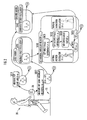
- An exercise management system 1 shown in Fig. 1 is for setting a recommended walking ratio suitable in consideration of activation of physical functions of a user (human being (animal)) or the like, using a treadmill (first motion induction device) 10 and a walking motion induction device (second motion induction device) 20.
- the exercise management system 1 is also for training the user by causing the user to walk with a scale and rhythm corresponding to the recommended walking ratio, while realizing harmonization between the user's walking or running motion, the operation of the treadmill 10, and the operation of the walking motion induction device 20.
- the treadmill 10 includes a driving roller 11 having a width slightly wider than the typical width of the human being, a driven roller 12 having an approximately same width as the driving roller 11, an endless belt (circular motion body) 13 looped over the driving roller 11 and the driven roller 12, and a footplate 14 which supports from below the portion of the endless belt 13 on which the user stands.
- the driving roller 11 is driven by a drive mechanism 101 composed of a motor, transmission and the like. As the driving roller 11 is driven in the clockwise direction in the figure, the belt 13 rotates in the clockwise direction with the driven roller 12 driven in apposition. This induces the user on the belt 13 to walk (or run) to the left in the figure.
- a speed sensor 102 which outputs a signal responsive to the moving speed of the belt 13, and a pressure sensor 104 which outputs a signal responsive to the pressure received by the footplate 14.
- a physiological variable sensor 106 which is attached to the user's body, outputs a signal responsive to a physiological variable b such as the heart rate.
- the physiological variable sensor 106 is attached to the user's body in a suitable manner depending on the physiological variable b to be used.
- the treadmill 10 may be of any known configuration, including a commercially available one.
- the walking motion induction device 20 includes a waist orthosis 21, thigh orthoses 22, force transmitting members 23, a battery 24, actuators (electric motors) 25, and hip joint angle sensors 26.
- the waist orthosis 21 is made of rigid and flexible materials combined, and is attached to a user's waist.
- the thigh orthosis 22 is also made of combined rigid and flexible materials, and is attached to each of the front and back of a user's thigh.
- the force transmitting member 23, which is made of lightweight rigid plastic or any other material having a good shape retention property, extends downward from each side of the user's waist along the user's corresponding thigh and then bifurcates toward the front and back of the thigh. It is connected to the actuator 25 and the respective thigh orthoses 22.
- the battery 24 is housed in the waist orthosis 21 (for example, fixed between a plurality of materials constituting the waist orthosis 21) and supplies electric power to the actuator 25 and the like.
- the actuator 25 is mounted on the waist orthosis 21 and applies a force to the user's thigh via the force transmitting member 23 and the thigh orthosis 22.
- the hip joint angle sensor 26 is composed of a rotary encoder and the like provided on each of the sides of the user's waist, and outputs a signal responsive to a hip joint angle.
- the exercise management system 1 includes a first control unit 100 and a second control unit 200.
- the first control unit 100 is composed of a computer such as a microcomputer attached to the treadmill 10, and controls the speed of the driving roller 11 driven by the drive mechanism 102 and the like.
- the first control unit 100 includes a motion variable measuring unit 110, a physiological variable measuring unit 120, and a recommended walking ratio setting unit 130.
- the motion variable measuring unit 110, the physiological variable measuring unit 120, and the recommended walking ratio setting unit 130 are each composed of a computer (containing CPU, ROM, RAM, I/O (input/output device) and others) serving as hardware and a part of the "exercise management program" of the present invention serving as software for providing functions to the computer.
- the motion variable measuring unit 110 includes a first motion variable measuring unit 111 and a second motion variable measuring unit 112.
- the first motion variable measuring unit 111 measures the user's walking speed v as a first motion variable, based on an output of the speed sensor 102.
- the walking speed v increases as the user's walking motion scale increases or the walking motion rhythm becomes faster, and thus, the first motion variable corresponds to the motion variable representing both the motion scale and the motion rhythm of the user.
- the second motion variable measuring unit 112 measures the user's walking rate (the number of steps per unit time) p as a second motion variable, based on an output of the pressure sensor 104.
- the walking rate p increases as the user's walking rhythm becomes faster, and thus, the second motion variable corresponds to the motion variable representing the motion rhythm of the user.
- the physiological variable measuring unit 120 measures a physiological variable b representing the user's physiological condition, based on an output of the physiological variable sensor 106 attached to the user's body.
- the recommended walking ratio setting unit 130 sets a recommended walking ratio k 0 , based on the user's walking ratio k measured by the motion variable measuring unit 110 and the physiological variable b measured by the physiological variable measuring unit 120.
- the second control unit (corresponding to the "control unit” of the present invention) 200 is composed of a computer housed in the waist orthosis 21 of the walking motion induction device 20 and the "exercise management program" of the present invention serving as the software providing the computer with the control function of the walking motion induction device 20 and the like.
- the second control unit 200 includes a motion oscillator measuring unit 210, a first oscillator generating unit 220, a natural angular velocity setting unit 230, a second oscillator generating unit 240, and an induction oscillator generating unit 250.
- the motion oscillator measuring unit 210 measures the user's hip joint angle ⁇ H , based on an output of the hip joint angle sensor 26, as a "second motion oscillator” that periodically changes according to the walking motion.
- the hip joint angle ⁇ H increases in amplitude as the user's walking motion scale (represented by the step width or the like) increases, and thus, it corresponds to the motion oscillator representing the user's motion scale.
- the motion oscillator measuring unit 210 measures a hip joint angular velocity d ⁇ H /dt as a "first motion oscillator", based on an output of the hip joint angle sensor 26.
- the hip joint angular velocity d ⁇ H /dt increases in amplitude as the user's walking motion rhythm (represented by the waking rate or the like) becomes faster, and thus, it corresponds to the motion oscillator representing the user's motion rhythm.
- the first oscillator generating unit 220 generates a first oscillator x according to a first model, based on the hip joint angular velocity d ⁇ H /dt measured by the motion oscillator measuring unit 210 and a natural angular velocity ⁇ M .
- the "first model” is a model for generating an output oscillation signal that changes over time at an angular velocity determined based on the natural angular velocity ⁇ M , by mutual entrainment with the input oscillation signal.
- the natural angular velocity setting unit 230 includes a first phase difference setting unit 231, a second phase difference setting unit 232, a correlation factor setting unit 233, a first angular velocity setting unit 234, and a second angular velocity setting unit 235.
- the first phase difference setting unit 231 sets a phase difference between the angular velocity ⁇ H of the hip joint angular velocity d ⁇ H /dt and the oscillator x reflecting the natural angular velocity ⁇ M included in a van der Pol equation, as a first phase difference ⁇ 1 .
- the correlation factor setting unit 233 sets a correlation factor ⁇ between the virtual motion oscillator ⁇ h and the virtual induction oscillator ⁇ m so that the second phase difference ⁇ 2 set by the second phase difference setting unit 232 approaches the first phase difference ⁇ 1 set by the first phase difference setting unit 231.
- the first angular velocity setting unit 234 sets an angular velocity ⁇ h of the virtual motion oscillator ⁇ h based on the correlation factor ⁇ set by the correlation factor setting unit 233.
- the second angular velocity setting unit 235 sets an angular velocity ⁇ m of the virtual induction oscillator ⁇ m , as a new natural angular velocity ⁇ M , based on the angular velocity ⁇ h of the virtual motion oscillator ⁇ h set by the first angular velocity setting unit 234, so that the second phase difference ⁇ 2 set by the second phase difference setting unit 232 approaches a target phase difference ⁇ d set by a target phase difference setting unit 212.
- the second oscillator generating unit 240 generates a second oscillator y, according to a second model, based on the hip joint angle ⁇ H measured by the motion oscillator measuring unit 210 and the natural angular velocity ⁇ M set by the natural angular velocity setting unit 230.
- the "second model” is a model for generating an output oscillation signal that changes over time at the angular velocity determined based on the natural angular velocity ⁇ M , based on an input oscillation signal.
- the induction oscillator generating unit 250 includes a first induction oscillator generating unit 251 and a second induction oscillator generating unit 252.
- the first induction oscillator generating unit 251 generates a first induction oscillator z 1 based on the second oscillator y generated by the second oscillator generating unit 240 and the natural angular velocity ⁇ M set by the natural angular velocity setting unit 230.
- the first induction oscillator z 1 represents an elastic force of an elastic element, such as a virtual spring, that causes the hip joint angle ⁇ H measured by the motion oscillator measuring unit 210 to approach its target value ⁇ 0 .
- the second induction oscillator generating unit 252 generates a second induction oscillator z 2 based on the second oscillator y generated by the second oscillator generating unit 240 and the natural angular velocity ⁇ M set by the natural angular velocity setting unit 230. It represents a damping force of a damping element, such as a virtual damper, that suppresses an increase in absolute value of the hip joint angle ⁇ H according to the hip joint angular velocity d ⁇ H /dt measured by the motion oscillator measuring unit 210.
- a damping element such as a virtual damper
- the induction oscillator generating unit 250 generates an induction oscillator z, based on the first induction oscillator z 1 and the second induction oscillator z 2 , as an instruction signal of the torque T around the hip joint which is to be applied to the user by the walking motion induction device 20.
- the first control unit 100 and the second control unit 200 are communicable in a wireless manner. It is noted that the plurality of processing units 110 (111, 112)1, 120, 130, 210, 220, ... constituting the exercise management system may be arranged in any arbitrary pattern in the first control unit 100 and the second control unit 200; for example, the recommended walking ratio setting unit 130 may be provided in the second control unit 200 instead of the first control unit 100. Further, the first control unit 100 and the second control unit 200 may be configured with a same computer. The first control unit 100 and the second control unit 200 may also communicate with each other via a cable.
- the first control unit 100 controls the operation of the treadmill 10 to keep the speed of the belt 13 constant, to thereby induce the user's walking motion in the opposite direction from the movement of the belt 13 at an approximately constant speed.
- the first model is a model which expresses the correlation of a plurality of first elements, such as the left and right legs, whose outputs change in accordance with the motion oscillator such as the hip joint angular velocity d ⁇ H /dt, using the van der Pol equations represented by the following expressions (1).
- " ⁇ " is a coefficient (>0) that is set so that the first oscillator x and its one-time temporal differentiation (dx/dt) draw stable limit cycles on the x-(dx/dt) plane.
- g is a first correlation factor representing the correlation of the left and right legs (first elements) in the first model.
- K is a feedback coefficient. It is noted that the natural angular velocity ⁇ M may be set arbitrarily within the range not largely deviating from the actual walking assist rhythm (walking induction rhythm) by the walking motion induction device 20.
- the first oscillator x (x L , x R ) is calculated or generated according to the Runge-Kutta method.
- the components x L and x R of the first oscillator x represent the walking assist rhythms for the left and right legs, respectively.
- the oscillator x tends to oscillate or periodically change at an autonomous rhythm or angular velocity reflecting the natural angular velocity ⁇ M , while being harmonized with the hip joint angular velocity d ⁇ H /dt that changes over time at the rhythm or angular velocity approximately the same as that of the actual walking motion, by virtue of the "mutual entrainment" which is a property of the van der Pol equation.
- the first oscillator x may be generated based on any kind of oscillator that oscillates in a rhythm reflecting the user's walking motion rhythm (motion rhythm), such as a hip joint angle ⁇ H , angle or angular velocity of knee joint, ankle joint, shoulder joint, elbow joint or the like, the walker's landing sound, respiratory sound, intermittently generated voice sound, or the like, instead of or in addition to the hip joint angular velocity d ⁇ H /dt.
- motion rhythm such as a hip joint angle ⁇ H , angle or angular velocity of knee joint, ankle joint, shoulder joint, elbow joint or the like, the walker's landing sound, respiratory sound, intermittently generated voice sound, or the like, instead of or in addition to the hip joint angular velocity d ⁇ H /dt.
- the first model may be expressed by a van der Pol equation in the form different from that of the van der Pol equation represented by the expression (1).
- the first model may be expressed by any kind of equation that can generate an oscillator with the effect of mutual entrainment with the motion oscillator such as the hip joint angular velocity d ⁇ H /dt.
- the first oscillator x is generated as an output of the first element, according to the first model which represents the relationship of the plurality of first elements (left and right legs) whose outputs change in accordance with the motion oscillator such as the hip joint angular velocity d ⁇ H /dt (expression (1), s020 in Fig. 2 ). Accordingly, an appropriate first oscillator x can be generated in consideration of the relationship between the plurality of first elements, by allowing the correlation between the plurality of first elements concerning the user's actual motion to be reflected to the first correlation factor g and the like in the first model.
- the first oscillator x is generated so as to reflect the qualitative relationship between the left and right legs such as their alternate backward and forward movements, or the qualitative relationship between the joints of the same leg such as the period or phase difference between the leg motion around the hip joint and the leg motion around the knee joint. This allows the rhythm and scale of the induction oscillator inducing the user's motion to be set as appropriate in consideration of the relationship concerned.
- the natural angular velocity setting unit 230 sets a natural angular velocity ⁇ M according to a virtual model including two virtual oscillators, based on the target phase difference ⁇ d stored in the memory and the first oscillator x generated by the first oscillator setting unit 210 (s030 in Fig. 2 ).
- the first phase difference measuring unit 231 firstly sets, for each of the left and right components, a phase difference ⁇ H - ⁇ M between the phase ⁇ H of the hip joint angular velocity d ⁇ H /dt measured by the motion oscillator measuring unit 210 and the phase ⁇ M of the first oscillator x generated by the first oscillator setting unit 210, as a first phase difference ⁇ 1 (s031 in Fig. 2 ).
- the second phase difference setting unit 232 sets the phase difference ⁇ h - ⁇ m between the virtual motion oscillator ⁇ h and the virtual induction oscillator ⁇ m represented by the following expression (2.3) as a second phase difference ⁇ 2 , for each of the left and right components, according to the "virtual model" represented by the following expressions (2.1) and (2.2) (s032 in Fig. 2 ).
- ⁇ h is an angular velocity of the virtual motion oscillator ⁇ h
- ⁇ m is an angular velocity of the virtual induction oscillator ⁇ m .
- the correlation factor setting unit 233 sets a correlation factor ⁇ such that the difference ⁇ 1 - ⁇ 2 between the first phase difference ⁇ 1 set by the first phase difference setting unit 231 and the second phase difference ⁇ 2 set by the second phase difference setting unit 232 becomes minimal (s033 in Fig. 2 ).
- ⁇ ⁇ t id + 1 ⁇ t id - ⁇ V 1 ⁇ t id + 1 - V 1 t id / ⁇ t id - ⁇ ⁇ t id - 1 , V ⁇ t id + 1 ⁇ 1 / 2 ⁇ ⁇ 1 ⁇ t id + 1 - ⁇ 2 t id ⁇ ⁇ 2
- the first angular velocity setting unit 234 sets the angular velocity ⁇ h of the virtual motion oscillator ⁇ h according to the following expression (2.5), for each of the left and right components, based on the correlation factor ⁇ set by the correlation factor setting unit 233, so that each component of the difference ⁇ 1 - ⁇ 2 between the first and second phase differences becomes minimal (s034 in Fig. 2 ).
- ⁇ h t id - ⁇ ⁇ dt ( [ 4 ⁇ ⁇ ( t id ⁇ ) 2 - ⁇ ⁇ h t - ⁇ m t id ⁇ ⁇ 2 ] 1 / 2 ⁇ sin sin - 1 ⁇ h t - ⁇ m ⁇ t id - 1 / 2 ⁇ ⁇ t id - ⁇ 1 t id
- each component of ⁇ ( ⁇ L , ⁇ R ) is a coefficient which represents stability of the system.
- the second angular velocity setting unit 235 sets the angular velocity ⁇ m of the virtual induction oscillator ⁇ m as a new natural angular velocity ⁇ M , for each of the left and right components, based on the angular velocity ⁇ h of the virtual motion oscillator ⁇ h set by the first angular velocity setting unit 234 (s035 in Fig. 2 ).
- ⁇ m t id ⁇ ⁇ dt • 4 ⁇ ⁇ ( t id ⁇ ) 2 - ⁇ ⁇ h t - ⁇ m t id ⁇ ⁇ 2 ⁇ sin sin - 1 ⁇ h t id - ⁇ m t / 2 ⁇ ⁇ t id - ⁇ d
- each component of ⁇ ( ⁇ L , ⁇ R ) is a coefficient representing stability of the system.
- the second model is a model which represents correlation between a plurality of second elements such as a plurality of neural elements whose outputs change in accordance with the motion oscillator such as the hip joint angle ⁇ H .
- the coefficients c, c 0 , c 1 , c 2 of f 1 ( ⁇ M ) and f 2 ( ⁇ M ), the functions of the new natural angular velocity ⁇ M may be set as coefficients corresponding to a target motion rhythm set by a target motion setting unit 211.
- the second oscillator y i may be generated based on any kind of oscillator that oscillates in a rhythm linked to the walking motion rhythm, such as a hip joint angular velocity d ⁇ H /dt, angle or angular velocity of knee joint, ankle joint, shoulder joint, elbow joint or the like, the walker's landing sound, respiratory sound, intermittently generated voice sound, or the like, instead of or in addition to the hip joint angle ⁇ H .
- the second oscillator y i is 0 when the value of the motion variable u i is less than a threshold value u th ; while when the value of the motion variable u i is not less than the threshold value u th , it takes the value of u i .
- the second oscillator y i is defined by a sigmoid function fs (see the expression (3)).
- the second oscillators y L- and y R- corresponding to the outputs of the second elements L- and R-, respectively, which govern those motions become greater than the outputs of the other second elements.
- the frontward or backward motion of the leg (thigh) is identified, e.g., by the polarity of the hip joint angular velocity d ⁇ H /dt.
- the second oscillator y i is generated as the output of the second element i, according to the second model which expresses the relationship between a plurality of second elements whose outputs change according to the motion oscillator such as the hip joint angular velocity d ⁇ H /dt (the expression (3), s040 in Fig. 2 ).
- the motion oscillator such as the hip joint angular velocity d ⁇ H /dt (the expression (3), s040 in Fig. 2 ).
- the second oscillator y i is generated in the form reflecting the qualitative relationship between the neurons governing the walking by the left and right legs or the like. This enables the rhythm and scale of the induction oscillator inducing the user's motion to be set as appropriate in consideration of the relationship concerned.
- the induction oscillator generating unit 250 sets the induction oscillator z, based on the hip joint angle ⁇ H and the hip joint angular velocity d ⁇ H /dt measured by the motion oscillator measuring unit 210, the second oscillator y i generated by the second oscillator generating unit 240, and the natural angular velocity ⁇ M set by the natural angular velocity setting unit 230 (s050 in Fig. 3 ).
- a first induction oscillator z 1 is generated according to the following expression (4) (s051 in Fig. 3 ).
- z 1 ⁇ L g 1 + ⁇ mL ⁇ g + ⁇ HL ⁇ y L + - g 1 - ⁇ mL ⁇ g - ⁇ HL ⁇ y L -
- z 1 ⁇ R g 1 + ⁇ mR ⁇ g + ⁇ HR ⁇ y R + - g 1 - ⁇ mR ⁇ g - ⁇ HR ⁇ y RR -
- the first coefficients g 1+ and g 1- represent the gradients of a first potential (a potential of an elastic element such as a virtual spring) which cause the hip joint angle (the motion oscillator in accordance with the user's motion scale) ⁇ H to approach the target angles ⁇ 0+ (>0) and ⁇ 0- ( ⁇ 0) in accordance with the target motion scale, according to the natural angular velocity ⁇ M (see the expressions (4.1) and (4.2)).
- a first potential a potential of an elastic element such as a virtual spring
- the first induction oscillator z 1 represents elastic forces of the virtual elastic elements which have the first coefficients g 1+ , g 1- as the elastic coefficients (spring coefficients) and which restore the value of the hip joint angle ⁇ H to the target angles ⁇ 0+ and ⁇ 0- .
- This enables the user's motion to be induced with the rhythm and scale reflecting the elastic elements of the user's body such as the elastic force generated during the transition from the muscle contraction state to the muscle stretch state.
- the elastic force of the virtual spring G 1+ represents the force that acts on the user's thigh to bring the hip joint angle ⁇ H close to its target value ⁇ 0+ according to the spring coefficient g 1+ (see the expression (4)). Specifically, when the hip joint angle ⁇ H is less than the target angle ⁇ 0+ , the elastic force of the spring G 1+ represents the force that acts on the thigh in such a way as to move the thigh in the direction of increasing the hip joint angle ⁇ H (forward).
- the elastic force of the spring G 1+ represents the force that acts on the thigh in such a way as to move the thigh in the direction of decreasing the hip joint angle ⁇ H (backward).
- the elastic force of the other virtual spring G 1- represents the force that acts on the user's thigh to bring the hip joint angle ⁇ H close to the target angle ⁇ 0- according to the spring coefficient g 1- (see the expression (4)).
- the elastic force of the spring G 1- represents the force that acts on the thigh in such a way as to move the thigh in the direction of decreasing the hip joint angle ⁇ H (backward).
- the elastic force of the spring G 1- represents the force that acts on the thigh in such a way as to move the thigh in the direction of increasing the hip joint angle ⁇ H (forward).
- the first induction oscillator Z 1L represented by the expression (4) is approximated by the following expression (4a).
- the output of the second element L- which is one of the elements governing this motion, or, the value of the second oscillator y L- , becomes greater than the output of the other second element L+, or, the value of the second oscillator y L+ .
- the first induction oscillator Z 1L represented by the expression (4) is approximated by the following expression (4b).
- a sigmoid function fs (see the expression (3)) having the hip joint angular velocity d ⁇ H /dt as a variable may be incorporated into the first coefficients g 1+ , g 1- , and a first torque T 1 may be generated in the form unevenly reflecting part of the second oscillators y i as the outputs of the plurality of second elements i, in accordance with the forward or backward movement of the thigh specified by the polarity of the hip joint angular velocity d ⁇ H /dt. This again prevents the elastic forces of the two virtual springs G 1+ and G 1- from being cancelled out.
- a second induction oscillator z 2 is set according to the following expression (5) (s052 in Fig. 2 ).
- the second coefficients g 2+ and g 2- represent the gradients of a second potential (a potential of a damping element such as a virtual damper) which suppress an increase in absolute value of the hip joint angle ⁇ H according to the natural angular velocity ⁇ M (see the expressions (5.1) and (5.2)).
- the second induction oscillator z 2 is represented as damping forces of the virtual damping elements which have the second coefficients g 2+ , g 2- as the damping coefficients (damper coefficients) and which suppress an increase in absolute value of the hip joint angle ⁇ H according to the hip joint angular velocity d ⁇ H /dt.
- This enables the user's motion to be induced with the rhythm and scale reflecting the damping elements of the user's body such as the viscous force generated during the transition from the muscle stretch state to the muscle flexed state.
- the damping force of one virtual damper G 2+ represents the force that acts on the user's thigh to prevent an increase in absolute value of the hip joint angle ⁇ H toward the front side (bending side), according to the damper coefficient g 2+ and the hip joint angular velocity d ⁇ H /dt (see the expression (5)).
- the damping force of the virtual damper G 2+ represents the force that acts on the thigh in such a way as to prevent the excessive forward movement of the thigh.
- the elastic force of the other virtual damper G 2- represents the force that acts on the user's thigh to prevent an increase in absolute value of the hip joint angle ⁇ H toward the back side (stretch side), according to the damper coefficient g 2- and the hip joint angular velocity d ⁇ H /dt (see the expression (5)).
- the damping force of the virtual damper G 2- represents the force that acts on the thigh in such a way as to prevent the excessive backward movement of the thigh.
- the second induction oscillator z 2 includes step functions H + and H- as the functions of the hip joint angle ⁇ H . This prevents the damping forces of the two virtual dampers G 2+ and G 2- from being cancelled out.
- the motion variable measuring unit 110 measures the walking ratio k (s110 in Fig. 3 ). Specifically, the first motion variable measuring unit 101 measures the user's walking speed v based on the output of the speed sensor 102 responsive to the speed of the belt 13 of the treadmill 10 (s111 in Fig. 3 ). Further, the second motion variable measuring unit 112 measures the user's walking rate (the number of steps per unit time) p based on the number of times that the output of the pressure sensor 104 responsive to the pressure applied to the footplate 14 of the treadmill 10 attains the peak per unit time (sa112 in Fig. 2 ).
- the physiological variable measuring unit 120 measures a physiological variable b based on an output of the physiological variable sensor 106 (s120 in Fig. 3 ).
- the physiological variable b may include a part or all of the user's oxygen uptake, respiratory frequency, heart rate, pulse rate, blood pressure, arterial oxygen saturation, lactate level, myogenic potential, and consumed energy.
- the coefficients a k+ and a k- included in the respective first coefficients g 1+ ( ⁇ M ) and g 1- ( ⁇ M ), and the coefficients b k+ and b k- included in the respective second coefficients g 2+ ( ⁇ M ) and g 2- ( ⁇ M ) are updated. Updating the target angles ⁇ 0+ and ⁇ 0- may change the induction scale by the walking motion induction device 20, resulting in, modification of the user's step width q.
- updating a part or all of the coefficients a k+ , a k- , b k+ , and b k- may change the induction rhythm by the walking motion induction device 20, resulting in modification of the user's walking rate (target motion rhythm) p.
- the physiological variable b is measured sequentially in the state where the user's walking motion is induced with the walking ratio k changed sequentially by the walking motion induction device 20.
- the relationship between the walking ratio k and the physiological variable b is obtained, and the recommended walking ratio setting unit 130 sets a recommended walking ratio k 0 based on the relationship concerned (s130 in Fig. 3 ).
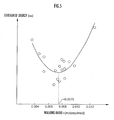
- the energy consumed by the user is measured as the physiological variable b and that the relationship between the walking ratio k and the consumed energy (physiological variable) as indicated by the circles (O) in Fig. 5 is obtained.
- the recommended walking ratio k 0 which is set to minimize the user's consumed energy, is an appropriate walking ratio k in consideration of reduction of the body load of the user.
- the physiological variable b other than the consumed energy such as the heart rate, lactate level (representing the degree of fatigue of the user's body), muscle group activity (representing the degree of activation of the physical functions) or the like, may be measured, and the recommended walking ratio k 0 may be set based on the measured variable b.
- the method of inducing the user's walking motion in accordance with the recommended walking ratio k 0 differs from the method of inducing the user's walking motion at the time of setting the recommended walking ratio k 0 only in the method of generating the induction oscillator z (s050 in Fig. 3 ). Therefore, description will not be repeated for measurement of the motion oscillator (s011 and s012 in Fig. 2 ), generation of the first oscillator x (s020 in Fig. 2 ), setting of the natural angular velocity ⁇ M (s030 in Fig. 2 ), and generation of the second oscillator y (s040 in Fig. 2 ).
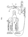
- the first motion variable measuring unit 111 measures the walking speed v of the user whose walking motion is induced by the operation of the treadmill 10 and the operation of the walking motion induction device 20 (s111 in Fig. 6 ).
- the induction oscillator generating unit 250 sets the induction oscillator z, based on the hip joint angle ⁇ H and the hip joint angular velocity d ⁇ H /dt measured by the motion oscillator measuring unit 210, the second oscillator y i generated by the second oscillator generating unit 240, and the natural angular velocity ⁇ M set by the natural angular velocity setting unit 230, and also based on the user's walking speed v measured by the first motion variable measuring unit 111 and the recommended walking ratio k 0 measured by the recommended walking ratio setting unit 130 (s250 in Fig. 2 ).
- a first induction oscillator z 1 is generated according to the following expression (6) (s251 in Fig. 6 ).
- a second induction oscillator z 2 is set according to the following expression (7) (s252 in Fig. 6 ).
- the second induction oscillator z 2 allows the user's walking motion to be induced so as to suppress an increase in absolute value of the hip joint angle ⁇ H according to the hip joint angular velocity d ⁇ H /dt.
- the current I corresponding to the induction oscillator z including the first induction oscillator z 1 and the second induction oscillator z 2 generated by the induction oscillator generating unit 250 is supplied from the battery 206 to the left and right actuators 210 to cause the forces (torques around the hip joints) T to be acted on the user's thighs.
- the walking ratio (motion variable) k and the physiological variable b are measured in the state where the user's motion is induced by the operation of the walking motion induction device (second motion induction device) 20 (s110, s120 in Fig. 3 ). Then, the value of the walking ratio k at the time when the physiological variable b attains an appropriate value in consideration of "activation of the physical functions" or "reduction of the body load” of the animal is set as a recommended target ratio k 0 . This ensures that the recommended walking ratio k 0 is set as appropriate in consideration of activation of the user's physical functions or the like.
- the user's walking motion is induced by the walking motion induction device 20 in accordance with the recommended walking ratio k 0 , which allows the induction scale and rhythm to be controlled appropriately so that the user's step width (motion scale) q and the walking rate (motion rhythm) p become appropriate in consideration of activation of the physical functions of the user or the like.
- the heart rate (physiological variable) of the same user walking at the same speed v varies depending on presence/absence of guidance of the walking motion by the walking motion induction device 20. Specifically, the heart rate when the user is walking without wearing the walking motion induction device 20 is higher than the heart rate when the user is walking wearing the walking motion induction device 20 that induces the walking motion. This means that the heart rate is restricted low and the load on the body is reduced in the state where the walking motion is induced to increase the user's step width as shown in Fig. 7 .
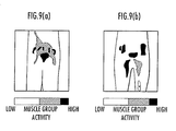
- the muscle group activity (physiological variable) in the case where the same user walks at the same speed v varies according to whether the walking motion is induced by the walking motion induction device 20.
- the results of the experiments shown in Figs. 7 to 9 indicate the important meaning of using the exercise management system 1 for managing exercise of, e.g., the user with motor deterioration like an aged person.
- the use of the exercise management system 1 of the present invention suppresses degradation of, and promotes activation of, the physical functions, while reducing the body load of the aged person or the like.
- the user's walking speed (first motion variable) v is measured based on the speed of the belt 13 of the treadmill 10 (s111 in Fig. 3 ).
- the user's walking rate (second motion variable) p is measured based on the pressure applied to the treadmill 10 which varies with repeated landing on and leaving from the floor of the user (s112 in Fig. 3 ). This improves the measurement accuracy of the walking ratio k which is a function of the walking speed v and the walking rate p (s110 in Fig. 3 ). Accordingly, it is possible to more accurately set the recommended value of the motion variable as appropriate in consideration of activation of the physical functions and/or reduction of the body load of the user.
- the circular movement of the endless belt (circular motion body) 13 of the treadmill 10 induces walking or running motion in the direction opposite from the movement of the endless belt 13. This enables the movement of the user by the walking or running to be cancelled out by the circular movement of the endless belt 13, thereby allowing setting of the recommended walking ratio k 0 for the user's walking or running motion only if there is a space for installing the treadmill 10.
- the recommended walking ratio k 0 may be set in the state where the user's walking motion is induced by the walking motion induction device 20 alone, without intervention of the treadmill 10.
- the exercise management system 1 may be used for setting a recommended value of the motion variable that varies with any motion other than the user's walking motion. For example, in the case where the hands are used to apply forces to the left and right wheels of a wheelchair, it may be used for setting a recommended value of a motion variable for another motion, such as the rhythm of pushing the wheels with the arms.
- the exercise management system 1 may also be used for setting a recommended value of a motion variable for motion of an animal other than the human being, such as running motion of a horse or the like.
- a recommended value of a motion variable as an arbitrary function of the walking speed v and the walking rate p may be set.
- a device other than the treadmill 10 which induces the motion of the user's physical site, such as the leg or arm, that comes into contact with a circular motion body, by circular movement of the circular motion body.
- the circular motion body may be: an endless belt looped over a plurality of rollers; a spherical body or oval sphere circulated about an axis passing the center or a point offset from the center; a tubular body such as a cylinder or square pole circulated about a central axis or an axis offset from and parallel to the central axis; or a block of substance circulated about an arbitrary axis.
- the torques around various joints such as knee joint, ankle joint, shoulder joint, elbow joint and carpal joint, may be applied to the user's body.
- the combination of the joints to which the torques are to be applied may be changed for each user.
- the second oscillator generating unit 240 of the second control unit 200 may generate the second oscillator y that oscillates in the rhythm or angular velocity determined based on one or both of the angular velocity (change of the phase over time) such as the hip joint angle ⁇ H measured by the motion oscillator measuring unit 210 and the angular velocity of the first oscillator x generated by the first oscillator generating unit 220, instead of the new natural angular velocity ⁇ M set by the natural angular velocity setting unit 230.
- the induction oscillator z may be generated according to the method as disclosed in Japanese Patent Application Laid-Open No. 2004-73649 .
- the induction oscillator z may be generated in the following manner.
- the motion oscillator measuring unit 210 measures motion oscillators corresponding to the user's different body parts (for example, a shoulder joint angular velocity and a hip joint angle) as a "first motion oscillator” and a "second motion oscillator", respectively.
- the first oscillator generating unit 220 generates a first oscillator x which attains mutual entrainment with the first motion oscillator in the form reflecting a natural angular velocity ⁇ M .
- the natural angular velocity setting unit 230 sets a new natural angular velocity ⁇ M based on the phase difference between the first motion oscillator and the first oscillator x.
- the second oscillator generating unit 240 generates a second oscillator y that oscillates with a rhythm reflecting the new natural angular velocity ⁇ M , based on the second motion oscillator. Then, the induction oscillator generating unit 250 generates an induction oscillator z based on one or both of the walking speed v (first motion variable) measured by the first motion variable measuring unit 101 and the walking rate p (second motion variable) measured by the second motion variable measuring unit 102, in addition to the second oscillator y.
- the user's motion can be induced so that the user's motion rhythm approaches the target motion rhythm, while harmonizing the motion rhythms of the user's different body parts with the rhythm of inducing the motion.
- the recommended walking ratio setting unit 130 may preliminarily set a plurality of recommended walking ratios k 0 for a plurality of users, respectively, by recognizing a plurality of identifiers for identification of the physical characteristics (including the body size, weight, age, gender and the like) of the respective users, and set a new recommended walking ratio k 0 based on the recommended walking ratio k 0 preliminarily set for each identifier recognized, to thereby establish a database having the identifiers and the recommended values associated with each other.
- the user's walking motion is induced based on the typical recommended value retrieved from the database in accordance with the user's identifier and hence the physical characteristics. This allows the induction scale and rhythm to be controlled appropriately so that the user's walking ratio k becomes appropriate in consideration of activation of the user's physical functions or the like.
Landscapes
- Health & Medical Sciences (AREA)
- Life Sciences & Earth Sciences (AREA)
- General Health & Medical Sciences (AREA)
- Physical Education & Sports Medicine (AREA)
- Animal Behavior & Ethology (AREA)
- Veterinary Medicine (AREA)
- Public Health (AREA)
- Biophysics (AREA)
- Pathology (AREA)
- Heart & Thoracic Surgery (AREA)
- Medical Informatics (AREA)
- Molecular Biology (AREA)
- Surgery (AREA)
- Engineering & Computer Science (AREA)
- Physics & Mathematics (AREA)
- Biomedical Technology (AREA)
- Physiology (AREA)
- Oral & Maxillofacial Surgery (AREA)
- Dentistry (AREA)
- Cardiology (AREA)
- Orthopedic Medicine & Surgery (AREA)
- Epidemiology (AREA)
- Pain & Pain Management (AREA)
- Rehabilitation Therapy (AREA)
- Vascular Medicine (AREA)
- Rehabilitation Tools (AREA)
- Selective Calling Equipment (AREA)
- Cash Registers Or Receiving Machines (AREA)
- Communication Control (AREA)
- Mobile Radio Communication Systems (AREA)
Abstract
Description
- The present invention relates to a system and method for managing exercise of an animal, and a program for providing a computer with the management function.
- There has been proposed a technique to determine an appropriate walking speed in consideration of a physiological index such as a user's electrocardiographic signal, for the purposes of setting a level of walking training for the user (for example, see Japanese Patent Application Laid-Open No.
2003-154029 - In the case where a device for inducing (or assisting) motion of the user's legs and the like by applying a force to the user's body is attached to the user, however, it has not been considered to set an induction scale and rhythm suitable for that user.
- In view of the foregoing, it is an object of the present invention to provide a system and method for managing exercise of an animal such as a human being so that its motion can be induced with an appropriate scale and rhythm in accordance with its physiological conditions, and a program for providing a computer with that management function.
- An exercise management system according to a first invention to achieve the above object includes: a control unit which controls an operation of a second motion induction device inducing motion of the animal while adjusting a motion scale of the animal at a rhythm harmonized with a motion rhythm of the animal; a physiological variable measuring unit which measures a physiological variable representing a physiological condition of the animal; a motion variable measuring unit which measures a motion variable representing one or both of the motion scale and the motion rhythm of the animal; and a recommended value setting unit which sets, as a recommended value of the motion variable, the motion variable that is measured by the motion variable measuring unit at the time when the physiological variable measured by the physiological variable measuring unit in the state where the motion of the animal is induced by the operation of the second motion induction device that is controlled by the control unit to change the motion variable attains an appropriate value in consideration of activation of physical functions or reduction of body load of the animal.
- According to the exercise management system of the first invention, the physiological variable and motion variable of the animal are measured in the state where the motion of the animal is induced by the operation of the second motion induction device. The "physiological variable" represents the physiological condition of the animal. The "motion variable" represents one or both of the motion scale and motion rhythm of the animal. The value of the motion variable obtained at the time when the physiological variable attains an appropriate value in consideration of "activation of physical functions" or "reduction of body load" of the animal is set as the recommended value of the motion variable. This ensures that the recommended value of the motion variable of the animal is set as appropriate in consideration of activation of the physical functions of the animal or the like. The motion of the animal is then induced by the second motion induction device according to this recommended value, which allows the induction scale and the induction rhythm to be controlled appropriately so that the motion scale and the motion rhythm of the animal are appropriate in consideration of activation of the physical functions of the animal or the like. In other words, the motion of the animal can be induced with an appropriate scale and rhythm in consideration of activation of the physical functions or the like, in accordance with the physiological conditions of the animal.
- Further, an exercise management system according to a second invention is characterized in that, in the exercise management system of the first invention, the control unit includes: a motion oscillator measuring unit which measures first and second motion oscillators as parameters that periodically change in accordance with the motion of the animal; a first oscillator generating unit which inputs the first motion oscillator measured by the motion oscillator measuring means as an input oscillation signal to a first model which generates an output oscillation signal that changes over time at an angular velocity determined based on a natural angular velocity by mutual entrainment with the input oscillation signal, to generate a first oscillator as the output oscillation signal; a natural angular velocity setting unit which sets a new natural angular velocity based on a phase difference between the motion oscillator measured by the motion oscillator measuring unit and the first oscillator generated by the first oscillator generating unit; a second oscillator generating unit which inputs the second motion oscillator measured by the motion oscillator measuring means as an input oscillation signal to a second model which generates an output oscillation signal that changes over time at an angular velocity determined based on the natural angular velocity set by the natural angular velocity setting means, to generate a second oscillator as the output oscillation signal; and an induction oscillator generating unit which generates an induction oscillator specifying a scale and rhythm of the operation of the second motion induction device, based on the motion variable measured by the motion variable measuring unit in addition to the second oscillator generated by the second oscillator generating unit.
- According to the exercise management system of the second invention, mutual adaptation or harmonization is established between the motion rhythm of the animal and the operation rhythm (inducing the motion of the animal)of the second motion induction device. This allows the motion of the animal to be induced at an appropriate scale and rhythm in consideration of activation of the physical functions or the like, while harmonizing the motion of the animal with the operation of the second motion induction device.
- Further, an exercise management system according to a third invention is characterized in that, in the exercise management system of the first invention, the physiological variable measuring unit measures part or all of oxygen uptake, respiratory frequency, heart rate, pulse rate, blood pressure, arterial oxygen saturation, lactate level, myogenic potential, and consumed energy of the animal as the physiological variable.
- According to the exercise management system of the third invention, the motion of the animal can be induced at an appropriate scale and rhythm in consideration of activation of the physical functions or the like, in accordance with the physiological condition represented by the oxygen uptake of the animal or the like.
- Further, an exercise management system according to a fourth invention is characterized in that, in the exercise management system of the first invention, the motion variable measuring unit includes a first motion variable measuring unit and a second motion variable measuring unit, the first motion variable measuring unit measures a first motion variable based on an operation speed of a first motion induction device which induces the motion of the animal while adjusting a motion speed of the animal, the first motion variable being the motion variable representing the motion scale and the motion rhythm of the animal the motion of which is induced by an operation of the first motion induction device, and the second motion variable measuring unit measures a second motion variable based on either a state of interaction between the first motion induction device and the animal or an operating state of the second motion induction device, the second motion variable being the motion variable representing the motion rhythm or the motion scale of the animal.
- According to the exercise management system of the fourth invention, the "first motion variable" is measured based on the speed of operation of the first motion induction device. Further, the "second motion variable" is measured based on either the interaction between the first motion induction device and the animal or the induction scale or induction rhythm by the second motion induction device. This improves the measurement accuracies of the first and second motion variables and of the motion variable as their function. Accordingly, it is possible to set a more appropriate recommended value of the motion variable in consideration of activation of the physical functions of the animal or the like.
- Further, an exercise management system according to a fifth invention is characterized in that, in the exercise management system of the fourth invention, the first motion variable measuring unit measures a walking or running speed of the animal as the first motion variable, and the second motion variable measuring unit measures a step width of the animal or a walking rate corresponding to the number of steps per unit time of the animal as the second motion variable.
- According to the exercise management system of the fifth invention, the recommended value of the motion variable, which is a function of walking or running speed of the animal and step width or walking rate, may be set as appropriate in consideration of activation of the physical functions and/or reduction of body load of the animal. The walking or running speed represents the motion scale and the motion rhythm of the animal. The step width represents the motion scale of the animal. The walking rate represents the motion rhythm of the animal. As the motion of the animal is induced based on this recommended value by the second motion induction device, the induction scale and rhythm may be controlled appropriately so that the step width or walking rate of the animal becomes appropriate in consideration of activation of the physical functions of the animal or the like.
- Further, an exercise management system according to a sixth invention is characterized in that, in the exercise management system of the fifth invention, the motion variable measuring unit measures, as the motion variable, a walking ratio corresponding to either a ratio of a square of the step width as the second motion variable with respect to the walking or running speed as the first motion variable, or a ratio of the walking or running speed as the first motion variable with respect to a square of the walking rate as the second motion variable.
- According to the exercise management system of the sixth invention, the recommended value of the walking ratio of the animal may be set as appropriate in consideration of activation of the physical functions and/or reduction of body load of the animal. Then, with the motion of the animal induced by the second motion induction device based on this recommended value, the induction scale and rhythm may be controlled appropriately so that the walking ratio of the animal becomes appropriate in consideration of activation of the physical functions of the animal or the like.
- Further, an exercise management system according to a seventh invention is characterized in that, in the exercise management system of the fourth invention, the first motion variable measuring unit measures the first motion variable of the animal the motion of which is being induced in a direction opposite from the direction of circular movement of a circular motion body provided in the first motion induction device, based on a speed of the circular movement of the circular motion body.
- According to the exercise management system of the seventh invention, the circular motion body provided in the first motion induction device is caused to perform circular movement to induce the motion of the animal whose body part is in contact with the circular motion body in the direction opposite from the direction of the circular movement of the circular motion body. The "circular motion body" may be: an endless belt looped over a plurality of rollers; a spherical body or oval sphere circulated about an axis passing the center or a point offset from the center; a tubular body such as a cylinder or square pole circulated about a central axis or an axis offset from and parallel to the central axis; or a block of substance circulated about an arbitrary axis. As the movement of the animal or its body part in accordance with its motion is cancelled out by the circular movement of the circular motion body, the recommended value of the motion variable of the animal can be set only if there is a space for installing the first motion induction device, and the space for installation can be selected relatively freely.
- Further, an exercise management system according to an eighth invention is characterized in that, in the exercise management system of the fourth invention, the first motion variable measuring unit measures the walking or running speed as the first motion variable representing a speed of the walking or running motion of the animal which is induced in a direction opposite from the movement of an endless belt serving as a circular motion body that is looped over a plurality of rollers provided in a treadmill serving as the first motion induction device, based on a driven speed of the endless belt.
- According to the exercise management system of the eighth invention, the circular movement of the endless belt (circular motion body) of the treadmill (first motion induction device) induces the walking or running motion of the animal in the direction opposite from the direction of the circular movement of the endless belt. As the movement of the animal by the walking or running motion is cancelled out by the circular movement of the endless belt, the recommended value of the motion variable for the walking or running motion of the animal can be set only if there is a space for installing the first motion induction device, and the installation space can be selected relatively freely.
- Further, an exercise management system according to a ninth invention is characterized in that, in the exercise management system of the first invention, the recommended value setting unit preliminarily sets a plurality of recommended values for a plurality of animals, respectively, by recognizing identifiers for identification of physical characteristics of the respective animals, and newly sets the recommended value based on the recommended value preliminarily set for each identifier recognized, to establish a database having the identifiers and the recommended values associated with each other.
- According to the exercise management system of the ninth invention, typical recommended values are set in accordance with the physical characteristics of the respective animals (including the body size, weight, age, gender and the like). With the motion of the animal induced based on this typical recommended value by the second motion induction device, the induction scale and rhythm may be controlled appropriately so that the motion variable of the animal becomes appropriate in consideration of activation of the physical functions of the animal or the like.
- A method according to a tenth invention to achieve the above object is a method for managing exercise of an animal, which includes the steps of: controlling an operation of a second motion induction device inducing motion of the animal while adjusting a motion scale of the animal at a rhythm harmonized with a motion rhythm of the animal; measuring a physiological variable representing a physiological condition of the animal; measuring a motion variable representing one or both of the motion scale and the motion rhythm of the animal; and setting, as a recommended value of the motion variable, the motion variable measured at the time when the physiological variable measured while the motion of the animal is induced by the operation of the second motion induction device controlled by the control unit to change the motion variable attains an appropriate value in consideration of activation of physical functions or reduction of body load of the animal.
- According to the exercise management method of the tenth invention, as in the exercise management system of the first invention, the recommended value of the motion variable of the animal may be set as appropriate in consideration of activation of the physical functions of the animal or the like. The motion of the animal is then induced by the second motion induction device according to this recommended value, which allows the induction scale and the induction rhythm to be controlled appropriately so that the motion scale and the motion rhythm of the animal become appropriate in consideration of activation of the physical functions of the animal or the like.
- A program according to an eleventh invention to achieve the above object is a program for causing a computer to function as a system for managing exercise of an animal, which is characterized by causing the computer to function as the system including: a control unit which controls an operation of a second motion induction device inducing motion of the animal while adjusting a motion scale of the animal at a rhythm harmonized with a motion rhythm of the animal; a physiological variable measuring unit which measures a physiological variable representing a physiological condition of the animal; a motion variable measuring unit which measures a motion variable representing one or both of the motion scale and the motion rhythm of the animal; and a recommended value setting unit which sets, as a recommended value of the motion variable, the motion variable that is measured by the motion variable measuring unit at the time when the physiological variable measured by the physiological variable measuring unit in the state where the motion of the animal is induced by the operation of the second motion induction device controlled by the control unit to change the motion variable attains an appropriate value in consideration of activation of physical functions or reduction of body load of the animal.
- According to the exercise management program of the eleventh invention, the computer is provided with the functions of managing exercise of the animal in such a manner that the recommended value of the motion variable of the animal may be set as appropriate in consideration of activation of the physical functions of the animal or the like. The functions may be provided to a single computer, or to a plurality of computers in a distributed manner.
-
-
Fig. 1 is an illustrative configuration diagram of an exercise management system of the present invention; -
Fig. 2 is an explanatory diagram regarding an exercise management method of the present invention; -
Fig. 3 is another explanatory diagram regarding the exercise management method of the present invention; -
Fig. 4 is an explanatory diagram of virtual springs and dampers inducing walking motion; -
Fig. 5 is an explanatory diagram regarding a method for setting a recommended walking ratio; -
Fig. 6 is another explanatory diagram regarding the exercise management method of the present invention; -
Fig. 7 is an explanatory diagram showing experimental results regarding the effects of the exercise management system of the present invention; -
Fig. 8 is another explanatory diagram showing experimental results regarding the effects of the exercise management system of the present invention; and -
Fig. 9 is another explanatory diagram showing experimental results regarding the effects of the exercise management system of the present invention. - Embodiments of the exercise management system, exercise management method, and exercise management program of the present invention will be described with reference to the drawings. Hereinafter, subscripts L and R will be attached to parameters to make a distinction between left and right for walker's legs or the like, although the subscripts L and R are omitted in the case where such distinction is not particularly necessary, for simplicity of notation.
- The configuration of the exercise management system of the present invention will now be described with reference to
Fig. 1 . - An
exercise management system 1 shown inFig. 1 is for setting a recommended walking ratio suitable in consideration of activation of physical functions of a user (human being (animal)) or the like, using a treadmill (first motion induction device) 10 and a walking motion induction device (second motion induction device) 20. Theexercise management system 1 is also for training the user by causing the user to walk with a scale and rhythm corresponding to the recommended walking ratio, while realizing harmonization between the user's walking or running motion, the operation of thetreadmill 10, and the operation of the walkingmotion induction device 20. - The
treadmill 10 includes a drivingroller 11 having a width slightly wider than the typical width of the human being, a drivenroller 12 having an approximately same width as the drivingroller 11, an endless belt (circular motion body) 13 looped over the drivingroller 11 and the drivenroller 12, and a footplate 14 which supports from below the portion of theendless belt 13 on which the user stands. The drivingroller 11 is driven by adrive mechanism 101 composed of a motor, transmission and the like. As the drivingroller 11 is driven in the clockwise direction in the figure, thebelt 13 rotates in the clockwise direction with the drivenroller 12 driven in apposition. This induces the user on thebelt 13 to walk (or run) to the left in the figure. Further provided are aspeed sensor 102 which outputs a signal responsive to the moving speed of thebelt 13, and apressure sensor 104 which outputs a signal responsive to the pressure received by thefootplate 14. A physiologicalvariable sensor 106, which is attached to the user's body, outputs a signal responsive to a physiological variable b such as the heart rate. The physiologicalvariable sensor 106 is attached to the user's body in a suitable manner depending on the physiological variable b to be used. Thetreadmill 10 may be of any known configuration, including a commercially available one. - The walking
motion induction device 20 includes awaist orthosis 21,thigh orthoses 22,force transmitting members 23, a battery 24, actuators (electric motors) 25, and hipjoint angle sensors 26. - The
waist orthosis 21 is made of rigid and flexible materials combined, and is attached to a user's waist. Thethigh orthosis 22 is also made of combined rigid and flexible materials, and is attached to each of the front and back of a user's thigh. Theforce transmitting member 23, which is made of lightweight rigid plastic or any other material having a good shape retention property, extends downward from each side of the user's waist along the user's corresponding thigh and then bifurcates toward the front and back of the thigh. It is connected to theactuator 25 and therespective thigh orthoses 22. The battery 24 is housed in the waist orthosis 21 (for example, fixed between a plurality of materials constituting the waist orthosis 21) and supplies electric power to theactuator 25 and the like. Theactuator 25 is mounted on thewaist orthosis 21 and applies a force to the user's thigh via theforce transmitting member 23 and thethigh orthosis 22. The hipjoint angle sensor 26 is composed of a rotary encoder and the like provided on each of the sides of the user's waist, and outputs a signal responsive to a hip joint angle. - The
exercise management system 1 includes afirst control unit 100 and asecond control unit 200. - The
first control unit 100 is composed of a computer such as a microcomputer attached to thetreadmill 10, and controls the speed of the drivingroller 11 driven by thedrive mechanism 102 and the like. Thefirst control unit 100 includes a motionvariable measuring unit 110, a physiologicalvariable measuring unit 120, and a recommended walkingratio setting unit 130. The motionvariable measuring unit 110, the physiologicalvariable measuring unit 120, and the recommended walkingratio setting unit 130 are each composed of a computer (containing CPU, ROM, RAM, I/O (input/output device) and others) serving as hardware and a part of the "exercise management program" of the present invention serving as software for providing functions to the computer. - The motion
variable measuring unit 110 includes a first motion variable measuring unit 111 and a second motionvariable measuring unit 112. The motionvariable measuring unit 110 measures a walking ratio k (= v/p2) as a motion variable, which is a function of walking speed v and walking rate p. - The first motion variable measuring unit 111 measures the user's walking speed v as a first motion variable, based on an output of the
speed sensor 102. The walking speed v increases as the user's walking motion scale increases or the walking motion rhythm becomes faster, and thus, the first motion variable corresponds to the motion variable representing both the motion scale and the motion rhythm of the user. - The second motion
variable measuring unit 112 measures the user's walking rate (the number of steps per unit time) p as a second motion variable, based on an output of thepressure sensor 104. The walking rate p increases as the user's walking rhythm becomes faster, and thus, the second motion variable corresponds to the motion variable representing the motion rhythm of the user. - The physiological
variable measuring unit 120 measures a physiological variable b representing the user's physiological condition, based on an output of the physiologicalvariable sensor 106 attached to the user's body. - The recommended walking
ratio setting unit 130 sets a recommended walking ratio k0, based on the user's walking ratio k measured by the motionvariable measuring unit 110 and the physiological variable b measured by the physiologicalvariable measuring unit 120. - The second control unit (corresponding to the "control unit" of the present invention) 200 is composed of a computer housed in the
waist orthosis 21 of the walkingmotion induction device 20 and the "exercise management program" of the present invention serving as the software providing the computer with the control function of the walkingmotion induction device 20 and the like. - The
second control unit 200 includes a motionoscillator measuring unit 210, a firstoscillator generating unit 220, a natural angularvelocity setting unit 230, a secondoscillator generating unit 240, and an inductionoscillator generating unit 250. - The motion
oscillator measuring unit 210 measures the user's hip joint angle φH, based on an output of the hipjoint angle sensor 26, as a "second motion oscillator" that periodically changes according to the walking motion. The hip joint angle φH increases in amplitude as the user's walking motion scale (represented by the step width or the like) increases, and thus, it corresponds to the motion oscillator representing the user's motion scale. Further, the motionoscillator measuring unit 210 measures a hip joint angular velocity dφH/dt as a "first motion oscillator", based on an output of the hipjoint angle sensor 26. The hip joint angular velocity dφH/dt increases in amplitude as the user's walking motion rhythm (represented by the waking rate or the like) becomes faster, and thus, it corresponds to the motion oscillator representing the user's motion rhythm. - The first
oscillator generating unit 220 generates a first oscillator x according to a first model, based on the hip joint angular velocity dφH/dt measured by the motionoscillator measuring unit 210 and a natural angular velocity ωM. The "first model" is a model for generating an output oscillation signal that changes over time at an angular velocity determined based on the natural angular velocity ωM, by mutual entrainment with the input oscillation signal. - The natural angular
velocity setting unit 230 includes a first phasedifference setting unit 231, a second phasedifference setting unit 232, a correlationfactor setting unit 233, a first angularvelocity setting unit 234, and a second angularvelocity setting unit 235. - The first phase
difference setting unit 231 sets a phase difference between the angular velocity ωH of the hip joint angular velocity dφH/dt and the oscillator x reflecting the natural angular velocity ωM included in a van der Pol equation, as a first phase difference δθ1. - The second phase
difference setting unit 232 sets, based on a "virtual model" representing the relationship between a virtual motion oscillator θh and a virtual induction oscillator (virtual induction oscillator) θm, a phase difference between the virtual motion oscillator θh and the virtual induction oscillator θm as a second phase difference δθ2 (= θh-θm). - The correlation
factor setting unit 233 sets a correlation factor ε between the virtual motion oscillator θh and the virtual induction oscillator θm so that the second phase difference δθ2 set by the second phasedifference setting unit 232 approaches the first phase difference δθ1 set by the first phasedifference setting unit 231. - The first angular
velocity setting unit 234 sets an angular velocity ωh of the virtual motion oscillator θh based on the correlation factor ε set by the correlationfactor setting unit 233. - The second angular
velocity setting unit 235 sets an angular velocity ωm of the virtual induction oscillator θm, as a new natural angular velocity ωM, based on the angular velocity ωh of the virtual motion oscillator θh set by the first angularvelocity setting unit 234, so that the second phase difference δθ2 set by the second phasedifference setting unit 232 approaches a target phase difference δθd set by a target phase difference setting unit 212. - The second
oscillator generating unit 240 generates a second oscillator y, according to a second model, based on the hip joint angle φH measured by the motionoscillator measuring unit 210 and the natural angular velocity ωM set by the natural angularvelocity setting unit 230. The "second model" is a model for generating an output oscillation signal that changes over time at the angular velocity determined based on the natural angular velocity ωM, based on an input oscillation signal. - The induction
oscillator generating unit 250 includes a first inductionoscillator generating unit 251 and a second inductionoscillator generating unit 252. - The first induction
oscillator generating unit 251 generates a first induction oscillator z1 based on the second oscillator y generated by the secondoscillator generating unit 240 and the natural angular velocity ωM set by the natural angularvelocity setting unit 230. The first induction oscillator z1 represents an elastic force of an elastic element, such as a virtual spring, that causes the hip joint angle φH measured by the motionoscillator measuring unit 210 to approach its target value φ0. The second inductionoscillator generating unit 252 generates a second induction oscillator z2 based on the second oscillator y generated by the secondoscillator generating unit 240 and the natural angular velocity ωM set by the natural angularvelocity setting unit 230. It represents a damping force of a damping element, such as a virtual damper, that suppresses an increase in absolute value of the hip joint angle φH according to the hip joint angular velocity dφH/dt measured by the motionoscillator measuring unit 210. Then, the inductionoscillator generating unit 250 generates an induction oscillator z, based on the first induction oscillator z1 and the second induction oscillator z2, as an instruction signal of the torque T around the hip joint which is to be applied to the user by the walkingmotion induction device 20. - The
first control unit 100 and thesecond control unit 200 are communicable in a wireless manner. It is noted that the plurality of processing units 110 (111, 112)1, 120, 130, 210, 220, ... constituting the exercise management system may be arranged in any arbitrary pattern in thefirst control unit 100 and thesecond control unit 200; for example, the recommended walkingratio setting unit 130 may be provided in thesecond control unit 200 instead of thefirst control unit 100. Further, thefirst control unit 100 and thesecond control unit 200 may be configured with a same computer. Thefirst control unit 100 and thesecond control unit 200 may also communicate with each other via a cable. - The functions of the
exercise management system 1 having the above-described configuration, particularly the method for setting the recommended walking ratio (recommended value of the motion variable) for the user, will now be described with reference toFigs. 2 to 5 . - The
first control unit 100 controls the operation of thetreadmill 10 to keep the speed of thebelt 13 constant, to thereby induce the user's walking motion in the opposite direction from the movement of thebelt 13 at an approximately constant speed. - In this state, the motion
oscillator measuring unit 210 measures the user's left and right hip joint angles φH = (φHL, φHR), based on the outputs of the hip joint angle sensors 26 (s011 inFig. 2 ). Further, the motionoscillator measuring unit 210 measures the user's left and right hip joint angular velocities dφH/dt = (dφHL/dt, dφHR/dt), based on the outputs of the hip joint angle sensors 26 (s012 inFig. 2 ). - The first
oscillator generating unit 220 sets a first oscillator x = (xL, xR) according to the first model, based on the hip joint angular velocity dφH/dt measured by the motionoscillator measuring unit 210 and the latest natural angular velocity ωM = (ωML, ωMR) stored in the memory (s020 inFig. 2 ). The first model is a model which expresses the correlation of a plurality of first elements, such as the left and right legs, whose outputs change in accordance with the motion oscillator such as the hip joint angular velocity dφH/dt, using the van der Pol equations represented by the following expressions (1). -

where "ξ" is a coefficient (>0) that is set so that the first oscillator x and its one-time temporal differentiation (dx/dt) draw stable limit cycles on the x-(dx/dt) plane. "g" is a first correlation factor representing the correlation of the left and right legs (first elements) in the first model. "K" is a feedback coefficient. It is noted that the natural angular velocity ωM may be set arbitrarily within the range not largely deviating from the actual walking assist rhythm (walking induction rhythm) by the walkingmotion induction device 20. - The first oscillator x = (xL, xR) is calculated or generated according to the Runge-Kutta method. The components xL and xR of the first oscillator x represent the walking assist rhythms for the left and right legs, respectively. The oscillator x tends to oscillate or periodically change at an autonomous rhythm or angular velocity reflecting the natural angular velocity ωM, while being harmonized with the hip joint angular velocity dφH/dt that changes over time at the rhythm or angular velocity approximately the same as that of the actual walking motion, by virtue of the "mutual entrainment" which is a property of the van der Pol equation.
- It is noted that the first oscillator x may be generated based on any kind of oscillator that oscillates in a rhythm reflecting the user's walking motion rhythm (motion rhythm), such as a hip joint angle φH, angle or angular velocity of knee joint, ankle joint, shoulder joint, elbow joint or the like, the walker's landing sound, respiratory sound, intermittently generated voice sound, or the like, instead of or in addition to the hip joint angular velocity dφH/dt.
- Further, the first model may be expressed by a van der Pol equation in the form different from that of the van der Pol equation represented by the expression (1). The first model may be expressed by any kind of equation that can generate an oscillator with the effect of mutual entrainment with the motion oscillator such as the hip joint angular velocity dφH/dt.
- As described above, the first oscillator x is generated as an output of the first element, according to the first model which represents the relationship of the plurality of first elements (left and right legs) whose outputs change in accordance with the motion oscillator such as the hip joint angular velocity dφH/dt (expression (1), s020 in
Fig. 2 ). Accordingly, an appropriate first oscillator x can be generated in consideration of the relationship between the plurality of first elements, by allowing the correlation between the plurality of first elements concerning the user's actual motion to be reflected to the first correlation factor g and the like in the first model. For example, in the case where the left and right legs, or a plurality of joints of the same leg, are assumed as the plurality of first elements, the first oscillator x is generated so as to reflect the qualitative relationship between the left and right legs such as their alternate backward and forward movements, or the qualitative relationship between the joints of the same leg such as the period or phase difference between the leg motion around the hip joint and the leg motion around the knee joint. This allows the rhythm and scale of the induction oscillator inducing the user's motion to be set as appropriate in consideration of the relationship concerned. - Subsequently, the natural angular
velocity setting unit 230 sets a natural angular velocity ωM according to a virtual model including two virtual oscillators, based on the target phase difference δθd stored in the memory and the first oscillator x generated by the first oscillator setting unit 210 (s030 inFig. 2 ). - Specifically, the first phase
difference measuring unit 231 firstly sets, for each of the left and right components, a phase difference θH - θM between the phase θH of the hip joint angular velocity dφH/dt measured by the motionoscillator measuring unit 210 and the phase θM of the first oscillator x generated by the firstoscillator setting unit 210, as a first phase difference δθ1 (s031 inFig. 2 ). - Next, on the condition that the first phase difference δθ1 set by the first phase
difference setting unit 231 remained constant over the past three walking periods, the second phasedifference setting unit 232 sets the phase difference θh - θm between the virtual motion oscillator θh and the virtual induction oscillator θm represented by the following expression (2.3) as a second phase difference δθ2, for each of the left and right components, according to the "virtual model" represented by the following expressions (2.1) and (2.2) (s032 inFig. 2 ). -


where ε = (εL, εR) is a correlation factor between the virtual motion oscillator θh = (θhL, θhR) and the virtual induction oscillator θm = (θmL, θmR) in the virtual model for each of the left and right components. Further, ωh is an angular velocity of the virtual motion oscillator θh, and ωm is an angular velocity of the virtual induction oscillator θm. - Subsequently, the correlation
factor setting unit 233 sets a correlation factor ε such that the difference δθ1-δθ2 between the first phase difference δθ1 set by the first phasedifference setting unit 231 and the second phase difference δθ2 set by the second phasedifference setting unit 232 becomes minimal (s033 inFig. 2 ). - Specifically, the correlation factor ε in a discrete time tid (d = 1, 2, ...) where the hip joint angular velocity (motion oscillator) dφH/dt becomes 0 is sequentially set for each of the left and right components, according to the following expression (2.4).
-

where each component of η = (ηL, ηR) is a coefficient which represents stability of the potential V = (VL, VR) that causes each of the left and right components of the first phase difference δθ1 to approach the corresponding component of the second phase difference δθ2. - Next, on the condition that the natural angular velocity ωm of the virtual induction oscillator θm is constant, the first angular
velocity setting unit 234 sets the angular velocity ωh of the virtual motion oscillator θh according to the following expression (2.5), for each of the left and right components, based on the correlation factor ε set by the correlationfactor setting unit 233, so that each component of the difference δθ1-δθ2 between the first and second phase differences becomes minimal (s034 inFig. 2 ). -

where each component of α = (αL, αR) is a coefficient which represents stability of the system. - Subsequently, the second angular
velocity setting unit 235 sets the angular velocity ωm of the virtual induction oscillator θm as a new natural angular velocity ωM, for each of the left and right components, based on the angular velocity ωh of the virtual motion oscillator θh set by the first angular velocity setting unit 234 (s035 inFig. 2 ). Specifically, the second angularvelocity setting unit 235 sets the angular velocity ωm = (ωmL, (ωmR) of the virtual induction oscillator θm according to the following expression (2.6), for each of the left and right components, so that the second phase difference δθ2 approaches the target phase difference δθd. -

where each component of β = (βL, βR) is a coefficient representing stability of the system. - Subsequently, the second
oscillator generating unit 240 generates a second oscillator y = (YL+, YL-, YR+, yR-) according to a second model, based on the hip joint angle φH measured by the motionoscillator measuring unit 210 and the new natural angular velocity ωM set by the natural angular velocity setting unit 230 (s040 inFig. 2 ). The second model is a model which represents correlation between a plurality of second elements such as a plurality of neural elements whose outputs change in accordance with the motion oscillator such as the hip joint angle φH. More specifically, the second model is expressed by the following simultaneous differential equations (3), which include: a motion variable ui (i = L+, L-, R+, R-) corresponding to changes in membrane potential of neural elements L+ and L- which govern the motions of the left thigh in the bending direction (forward) and the stretching direction (backward), respectively, and neural elements R+ and R- which govern the motions of the right thigh in the bending direction and the stretching direction, respectively; and a self-control factor vi reflecting an adaptive effect of the neural element i. -

where τ1i is a time constant which defines change characteristics of the motion variable ui and it has a dependence on the new natural angular velocity ωM as expressed by the following expression (3.1) for each of the left and right components. -

where "t(ω)" is a coefficient having a dependence on ω. "γ = (γL, γR)" is a constant. "τ2i" is a time constant which defines change characteristics of the self-control factor vi. "wi/j (<0)" is a second correlation factor representing the correlation between a plurality of second elements i and j. "λL" and "λR" are habituation coefficients. "K" is a feedback coefficient in accordance with the hip joint angle φH. - "f1" and "f2" are functions defined by the following expressions (3.2) and (3.3), respectively.
-


The coefficients c, c0, c1, c2 of f1(ωM) and f2(ωM), the functions of the new natural angular velocity ωM, may be set as coefficients corresponding to a target motion rhythm set by a target motion setting unit 211. - It is noted that the second oscillator yi may be generated based on any kind of oscillator that oscillates in a rhythm linked to the walking motion rhythm, such as a hip joint angular velocity dφH/dt, angle or angular velocity of knee joint, ankle joint, shoulder joint, elbow joint or the like, the walker's landing sound, respiratory sound, intermittently generated voice sound, or the like, instead of or in addition to the hip joint angle φH.
- The second oscillator yi is 0 when the value of the motion variable ui is less than a threshold value uth; while when the value of the motion variable ui is not less than the threshold value uth, it takes the value of ui. Alternatively, the second oscillator yi is defined by a sigmoid function fs (see the expression (3)). Thus, for the motions of the thighs in the bending direction (forward), the second oscillators yL+ and yR+ corresponding to the outputs of the second elements (neural elements) L+ and R+, respectively, which govern those motions become greater than the outputs of the other second elements. Further, for the motions of the thighs in the stretching direction (backward), the second oscillators yL- and yR- corresponding to the outputs of the second elements L- and R-, respectively, which govern those motions become greater than the outputs of the other second elements. The frontward or backward motion of the leg (thigh) is identified, e.g., by the polarity of the hip joint angular velocity dφH/dt.
- As described above, the second oscillator yi is generated as the output of the second element i, according to the second model which expresses the relationship between a plurality of second elements whose outputs change according to the motion oscillator such as the hip joint angular velocity dφH/dt (the expression (3), s040 in
Fig. 2 ). Thus, by causing the relationship between the plurality of second elements concerning the user's actual motion to be reflected to the second correlation factor wi/j in the second model, an appropriate second oscillator yi may be generated in consideration of the relationship between the actual elements. For example, in the case where the user's neurons are assumed to be the actual elements, the second oscillator yi is generated in the form reflecting the qualitative relationship between the neurons governing the walking by the left and right legs or the like. This enables the rhythm and scale of the induction oscillator inducing the user's motion to be set as appropriate in consideration of the relationship concerned. - Next, the induction
oscillator generating unit 250 sets the induction oscillator z, based on the hip joint angle φH and the hip joint angular velocity dφH/dt measured by the motionoscillator measuring unit 210, the second oscillator yi generated by the secondoscillator generating unit 240, and the natural angular velocity ωM set by the natural angular velocity setting unit 230 (s050 inFig. 3 ). - Specifically, a first induction oscillator z1 is generated according to the following expression (4) (s051 in
Fig. 3 ). -

where "g1+", "g1-", "g+", and "g-" are functions defined by the following expressions (4.1) to (4.4), respectively. -


The first induction oscillator z1 represents elastic forces of two virtual springs G1+ and G1-, as shown inFig. 4 , which have the first coefficients g1+ and g1-, respectively, as their spring coefficients (elastic coefficients). The first coefficients g1+ and g1- represent the gradients of a first potential (a potential of an elastic element such as a virtual spring) which cause the hip joint angle (the motion oscillator in accordance with the user's motion scale) φH to approach the target angles φ0+ (>0) and φ0- (<0) in accordance with the target motion scale, according to the natural angular velocity ωM (see the expressions (4.1) and (4.2)). That is, the first induction oscillator z1 represents elastic forces of the virtual elastic elements which have the first coefficients g1+, g1- as the elastic coefficients (spring coefficients) and which restore the value of the hip joint angle φH to the target angles φ0+ and φ0-. This enables the user's motion to be induced with the rhythm and scale reflecting the elastic elements of the user's body such as the elastic force generated during the transition from the muscle contraction state to the muscle stretch state. - The elastic force of the virtual spring G1+ represents the force that acts on the user's thigh to bring the hip joint angle φH close to its target value φ0+ according to the spring coefficient g1+ (see the expression (4)). Specifically, when the hip joint angle φH is less than the target angle φ0+, the elastic force of the spring G1+ represents the force that acts on the thigh in such a way as to move the thigh in the direction of increasing the hip joint angle φH (forward). When the hip joint angle φH exceeds the target angle φ0+, the elastic force of the spring G1+ represents the force that acts on the thigh in such a way as to move the thigh in the direction of decreasing the hip joint angle φH (backward).
- Moreover, the elastic force of the other virtual spring G1- represents the force that acts on the user's thigh to bring the hip joint angle φH close to the target angle φ0- according to the spring coefficient g1- (see the expression (4)). Specifically, when the hip joint angle φH exceeds the target angle φ0-, the elastic force of the spring G1- represents the force that acts on the thigh in such a way as to move the thigh in the direction of decreasing the hip joint angle φH (backward). When the hip joint angle φH is less than the target angle φ0-, the elastic force of the spring G1- represents the force that acts on the thigh in such a way as to move the thigh in the direction of increasing the hip joint angle φH (forward).
- Further, as described above, there are uneven outputs from some of the plurality of second elements i (= L+, L-, R+, R-) in accordance with the forward or backward movement of the thighs, which prevents the elastic forces of the two virtual springs G1+ and G1- from being cancelled out.
- Specifically, in the case where the left thigh is moving forward, the value of the second oscillator yL+ corresponding to the output of the second element L+, which is one of the elements governing this motion, becomes greater than the value of the second oscillator yL- corresponding to the output of the second element L-, which is the other element governing this motion. Accordingly, the first induction oscillator Z1L represented by the expression (4) is approximated by the following expression (4a).
-

Therefore, in the case where the left thigh is moving forward, of the elastic forces of the two virtual springs G1+ and G1-, the elastic force of the spring G1+ acting on the user's thigh in such a way as to bring the hip joint angle φH close to the target angle φ0+ for the front side is reflected predominantly. This avoids cancellation of the elastic forces of the two virtual springs G1+ and G1- with each other. - Further, in the case where the left thigh is moving backward, the output of the second element L-, which is one of the elements governing this motion, or, the value of the second oscillator yL-, becomes greater than the output of the other second element L+, or, the value of the second oscillator yL+. Accordingly, the first induction oscillator Z1L represented by the expression (4) is approximated by the following expression (4b).
-

Therefore, in the case where the left thigh is moving backward, of the elastic forces of the two virtual springs G1+ and G1-, the elastic force of the spring G1- acting on the user's thigh in such a way as to bring the hip joint angle φH close to the target angle φ0- for the back side is reflected predominantly. This avoids cancellation of the elastic forces of the two virtual springs G1+ and G1- with each other. The same applies to the motion of the right leg (thigh). - It is noted that a sigmoid function fs (see the expression (3)) having the hip joint angular velocity dφH/dt as a variable may be incorporated into the first coefficients g1+, g1-, and a first torque T1 may be generated in the form unevenly reflecting part of the second oscillators yi as the outputs of the plurality of second elements i, in accordance with the forward or backward movement of the thigh specified by the polarity of the hip joint angular velocity dφH/dt. This again prevents the elastic forces of the two virtual springs G1+ and G1- from being cancelled out.
- Furthermore, a second induction oscillator z2 is set according to the following expression (5) (s052 in
Fig. 2 ). -

where "g2+", "g2-", "H+", and "H-" are functions defined by the following expressions (5.1) to (5.4), respectively. -




The second induction oscillator z2 is understood as damping forces of two virtual dampers G2; and G2-, as shown inFig. 4 , which have the second coefficients g2+ and g2-, respectively, as damper coefficients (damping coefficients). The second coefficients g2+ and g2- represent the gradients of a second potential (a potential of a damping element such as a virtual damper) which suppress an increase in absolute value of the hip joint angle φH according to the natural angular velocity ωM (see the expressions (5.1) and (5.2)). That is, the second induction oscillator z2 is represented as damping forces of the virtual damping elements which have the second coefficients g2+, g2- as the damping coefficients (damper coefficients) and which suppress an increase in absolute value of the hip joint angle φH according to the hip joint angular velocity dφH/dt. This enables the user's motion to be induced with the rhythm and scale reflecting the damping elements of the user's body such as the viscous force generated during the transition from the muscle stretch state to the muscle flexed state. - The damping force of one virtual damper G2+ represents the force that acts on the user's thigh to prevent an increase in absolute value of the hip joint angle φH toward the front side (bending side), according to the damper coefficient g2+ and the hip joint angular velocity dφH/dt (see the expression (5)). In other words, the damping force of the virtual damper G2+ represents the force that acts on the thigh in such a way as to prevent the excessive forward movement of the thigh.
- Moreover, the elastic force of the other virtual damper G2- represents the force that acts on the user's thigh to prevent an increase in absolute value of the hip joint angle φH toward the back side (stretch side), according to the damper coefficient g2- and the hip joint angular velocity dφH/dt (see the expression (5)). In other words, the damping force of the virtual damper G2- represents the force that acts on the thigh in such a way as to prevent the excessive backward movement of the thigh.
- Furthermore, the second induction oscillator z2 includes step functions H+ and H- as the functions of the hip joint angle φH. This prevents the damping forces of the two virtual dampers G2+ and G2- from being cancelled out.
- Then, the currents I(z) = (IL(z1L+z2L) IR(z1R+z2R)) corresponding to the induction oscillator z (= z1+z2) including the first induction oscillator z1 = (z1L, z1R) and the second induction oscillator z2 = (z2L, z2R) generated by the induction
oscillator generating unit 250 are supplied from the battery 206 to the left andright actuators 210, respectively, thereby causing the forces (torques around the hip joints) T(I) corresponding to the supplied currents I to act on the user's thighs. - Thereafter, the above-described processing (s011, s012, ..., s040 in
Fig. 2 and s050 inFig. 3 ) is repeated to allow the user to walk, with the torque T around the hip joint applied to the user by the operation of the walkingmotion induction device 20. - Then, with the user's walking motion induced by the operations of the
treadmill 10 and the walkingmotion induction device 20 as described above, the motionvariable measuring unit 110 measures the walking ratio k (s110 inFig. 3 ). Specifically, the first motionvariable measuring unit 101 measures the user's walking speed v based on the output of thespeed sensor 102 responsive to the speed of thebelt 13 of the treadmill 10 (s111 inFig. 3 ). Further, the second motionvariable measuring unit 112 measures the user's walking rate (the number of steps per unit time) p based on the number of times that the output of thepressure sensor 104 responsive to the pressure applied to thefootplate 14 of thetreadmill 10 attains the peak per unit time (sa112 inFig. 2 ). The walking rate p may be measured based on the change over time of the torque T around the hip joint applied to the user by the walkingmotion induction device 20. Further, an acceleration sensor may be attached to the user's body, and the walking rate p may be measured based on the output of the acceleration sensor responsive to the acceleration in the vertical direction of the user. Then, the motionvariable measuring unit 100 measures the walking ratio k = v/p2 which is a function of the walking speed v and the walking rate p. - The physiological
variable measuring unit 120 measures a physiological variable b based on an output of the physiological variable sensor 106 (s120 inFig. 3 ). The physiological variable b may include a part or all of the user's oxygen uptake, respiratory frequency, heart rate, pulse rate, blood pressure, arterial oxygen saturation, lactate level, myogenic potential, and consumed energy. - Every time the physiological variable b is measured, part or all of the target angles φ0+ and φ0- of the hip joint angle φH, the coefficients ak+ and ak- included in the respective first coefficients g1+(ωM) and g1-(ωM), and the coefficients bk+ and bk- included in the respective second coefficients g2+(ωM) and g2-(ωM) are updated. Updating the target angles φ0+ and φ0- may change the induction scale by the walking
motion induction device 20, resulting in, modification of the user's step width q. Further, updating a part or all of the coefficients ak+, ak-, bk+, and bk- may change the induction rhythm by the walkingmotion induction device 20, resulting in modification of the user's walking rate (target motion rhythm) p. In this manner, the physiological variable b is measured sequentially in the state where the user's walking motion is induced with the walking ratio k changed sequentially by the walkingmotion induction device 20. Then, the relationship between the walking ratio k and the physiological variable b is obtained, and the recommended walkingratio setting unit 130 sets a recommended walking ratio k0 based on the relationship concerned (s130 inFig. 3 ). - For example, assume that the energy consumed by the user is measured as the physiological variable b and that the relationship between the walking ratio k and the consumed energy (physiological variable) as indicated by the circles (O) in
Fig. 5 is obtained. In this case, the relationship concerned is approximated by the quadric curve of the walking ratio k shown inFig. 5 , and the walking ratio k = 0.075 corresponding to the minimal value of the quadric curve is set as the recommended walking ratio k0 for the user. The recommended walking ratio k0, which is set to minimize the user's consumed energy, is an appropriate walking ratio k in consideration of reduction of the body load of the user. It is noted that the physiological variable b other than the consumed energy, such as the heart rate, lactate level (representing the degree of fatigue of the user's body), muscle group activity (representing the degree of activation of the physical functions) or the like, may be measured, and the recommended walking ratio k0 may be set based on the measured variable b. - Now, a method of inducing the user's walking motion by the walking
motion induction device 20 according to the recommended walking ratio k0 will be described with reference toFig. 6 . The method of inducing the user's walking motion in accordance with the recommended walking ratio k0 differs from the method of inducing the user's walking motion at the time of setting the recommended walking ratio k0 only in the method of generating the induction oscillator z (s050 inFig. 3 ). Therefore, description will not be repeated for measurement of the motion oscillator (s011 and s012 inFig. 2 ), generation of the first oscillator x (s020 inFig. 2 ), setting of the natural angular velocity ωM (s030 inFig. 2 ), and generation of the second oscillator y (s040 inFig. 2 ). - The first motion variable measuring unit 111 measures the walking speed v of the user whose walking motion is induced by the operation of the
treadmill 10 and the operation of the walking motion induction device 20 (s111 inFig. 6 ). - Further, the induction
oscillator generating unit 250 sets the induction oscillator z, based on the hip joint angle φH and the hip joint angular velocity dφH/dt measured by the motionoscillator measuring unit 210, the second oscillator yi generated by the secondoscillator generating unit 240, and the natural angular velocity ωM set by the natural angularvelocity setting unit 230, and also based on the user's walking speed v measured by the first motion variable measuring unit 111 and the recommended walking ratio k0 measured by the recommended walking ratio setting unit 130 (s250 inFig. 2 ). - Specifically, a first induction oscillator z1 is generated according to the following expression (6) (s251 in
Fig. 6 ). -

where "g1+", "g1-", "g+", and "g-" are functions defined by the following expressions (6.1) to (6.4), respectively. -


The first induction oscillator z1 allows the user's walking motion to be induced so that the hip joint angle φH matches the target angle φ0+, φ0- corresponding to the recommended walking ratio k0 and the walking speed v. - Furthermore, a second induction oscillator z2 is set according to the following expression (7) (s252 in
Fig. 6 ). -

where "g2+" and "g2-" are functions defined by the following expressions (7.1) and (7.2), respectively. -


The second induction oscillator z2 allows the user's walking motion to be induced so as to suppress an increase in absolute value of the hip joint angle φH according to the hip joint angular velocity dφH/dt. - The target angles φ0+(q0) and φ0-(q0) of the hip joint angle φH are each a function of a recommended step width q0 (= (vk0)1/2) corresponding to the recommended walking ratio k0 and the walking speed v, and may be corrected based on the deviation δq of the user's step width q (= v/p) from the recommended step width qo.
- Further, the coefficients ak+(p0) and ak-(p0) included in the first coefficients g1+(p0, ωM) and g1-(p0, ωM) and the coefficients bk+(p0) and bk-(p0) included in the second coefficients g2+(p0, ωM) and g2-(p0, ωM) are each a function of the recommended walking rate p0 (= (v/k0)1/2) corresponding to the recommended walking ratio k0 and the walking speed v, and may be corrected based on the deviation δp of the user's walking rate p (= v/q) from the recommended walking rate p0.
- Then, the current I corresponding to the induction oscillator z including the first induction oscillator z1 and the second induction oscillator z2 generated by the induction
oscillator generating unit 250 is supplied from the battery 206 to the left andright actuators 210 to cause the forces (torques around the hip joints) T to be acted on the user's thighs. - Thereafter, the above-described processing (s011, s012, ..., s040 in
Fig. 2 , s250 inFig. 6 ) is repeated to allow the user to walk in the state where the torque T around the hip joint is applied by the operation of the walkingmotion induction device 20. - According to the
exercise management system 1 exerting the above-described functions, the walking ratio (motion variable) k and the physiological variable b are measured in the state where the user's motion is induced by the operation of the walking motion induction device (second motion induction device) 20 (s110, s120 inFig. 3 ). Then, the value of the walking ratio k at the time when the physiological variable b attains an appropriate value in consideration of "activation of the physical functions" or "reduction of the body load" of the animal is set as a recommended target ratio k0. This ensures that the recommended walking ratio k0 is set as appropriate in consideration of activation of the user's physical functions or the like. The user's walking motion is induced by the walkingmotion induction device 20 in accordance with the recommended walking ratio k0, which allows the induction scale and rhythm to be controlled appropriately so that the user's step width (motion scale) q and the walking rate (motion rhythm) p become appropriate in consideration of activation of the physical functions of the user or the like. - Results of experiments regarding the effects of the
exercise management system 1 will now be described with reference toFigs. 7 to 9 . - As shown in
Fig. 7 , even if the same user walks at the same speed v, the walking ratio k varies according to whether the walking motion of the user is induced by the walkingmotion induction device 20. Specifically, when the user walks without wearing the walkingmotion induction device 20, the walking ratio k is controlled to about 0.0065. By comparison, in the case where the user walks wearing the walkingmotion induction device 20 that induces the walking motion, the walking ratio k is controlled to a recommended walking ratio k (= 0.0075) that has been set as described above. The walking motion of this user is induced by the operation of the walkingmotion induction device 20 so that the walking ratio k and, hence, the step width q increases. - Further, as shown in
Fig. 8 , the heart rate (physiological variable) of the same user walking at the same speed v varies depending on presence/absence of guidance of the walking motion by the walkingmotion induction device 20. Specifically, the heart rate when the user is walking without wearing the walkingmotion induction device 20 is higher than the heart rate when the user is walking wearing the walkingmotion induction device 20 that induces the walking motion. This means that the heart rate is restricted low and the load on the body is reduced in the state where the walking motion is induced to increase the user's step width as shown inFig. 7 . - Furthermore, as shown in
Fig. 9 , the muscle group activity (physiological variable) in the case where the same user walks at the same speed v varies according to whether the walking motion is induced by the walkingmotion induction device 20. The muscle group activity around the hip joints in the case where the user is walking wearing the walkingmotion induction device 20 and the walking motion is induced thereby, as shown inFig. 9(b) , is higher than the muscle group activity of the same sites when the user is walking without wearing the walkingmotion induction device 20, as shown inFig. 9(a) . This means that the user's physical functions are activated as the user's walking motion is induced to increase the step width as shown inFig. 7 . - The results of the experiments shown in
Figs. 7 to 9 indicate the important meaning of using theexercise management system 1 for managing exercise of, e.g., the user with motor deterioration like an aged person. In other words, the use of theexercise management system 1 of the present invention suppresses degradation of, and promotes activation of, the physical functions, while reducing the body load of the aged person or the like. - Further, the user's walking speed (first motion variable) v is measured based on the speed of the
belt 13 of the treadmill 10 (s111 inFig. 3 ). Furthermore, the user's walking rate (second motion variable) p is measured based on the pressure applied to thetreadmill 10 which varies with repeated landing on and leaving from the floor of the user (s112 inFig. 3 ). This improves the measurement accuracy of the walking ratio k which is a function of the walking speed v and the walking rate p (s110 inFig. 3 ). Accordingly, it is possible to more accurately set the recommended value of the motion variable as appropriate in consideration of activation of the physical functions and/or reduction of the body load of the user. - The circular movement of the endless belt (circular motion body) 13 of the
treadmill 10 induces walking or running motion in the direction opposite from the movement of theendless belt 13. This enables the movement of the user by the walking or running to be cancelled out by the circular movement of theendless belt 13, thereby allowing setting of the recommended walking ratio k0 for the user's walking or running motion only if there is a space for installing thetreadmill 10. The recommended walking ratio k0 may be set in the state where the user's walking motion is induced by the walkingmotion induction device 20 alone, without intervention of thetreadmill 10. - It is noted that the
exercise management system 1 may be used for setting a recommended value of the motion variable that varies with any motion other than the user's walking motion. For example, in the case where the hands are used to apply forces to the left and right wheels of a wheelchair, it may be used for setting a recommended value of a motion variable for another motion, such as the rhythm of pushing the wheels with the arms. Theexercise management system 1 may also be used for setting a recommended value of a motion variable for motion of an animal other than the human being, such as running motion of a horse or the like. Furthermore, instead of the walking ratio k, a recommended value of a motion variable as an arbitrary function of the walking speed v and the walking rate p may be set. - Moreover, for the first motion induction device, a device other than the
treadmill 10 may be adopted, which induces the motion of the user's physical site, such as the leg or arm, that comes into contact with a circular motion body, by circular movement of the circular motion body. The circular motion body may be: an endless belt looped over a plurality of rollers; a spherical body or oval sphere circulated about an axis passing the center or a point offset from the center; a tubular body such as a cylinder or square pole circulated about a central axis or an axis offset from and parallel to the central axis; or a block of substance circulated about an arbitrary axis. - In the above-described embodiment, the torques T = (TL, TR) around the left and right hip joints in accordance with the induction oscillator z are applied to the user's body. Alternatively, the torques around various joints, such as knee joint, ankle joint, shoulder joint, elbow joint and carpal joint, may be applied to the user's body. The combination of the joints to which the torques are to be applied may be changed for each user.
- Further, in the case where the magnitude of periodical change of the hip joint angle φH or the hip joint angular velocity dφH/dt (motion oscillator) measured by the motion
oscillator measuring unit 210 exceeds a threshold value, the secondoscillator generating unit 240 of thesecond control unit 200 may generate the second oscillator y that oscillates in the rhythm or angular velocity determined based on one or both of the angular velocity (change of the phase over time) such as the hip joint angle φH measured by the motionoscillator measuring unit 210 and the angular velocity of the first oscillator x generated by the firstoscillator generating unit 220, instead of the new natural angular velocity ωM set by the natural angularvelocity setting unit 230. - According to this configuration, even if the user's motion rhythm changes abruptly, the user's motion can be induced with an appropriate rhythm corresponding to the changed motion rhythm.
- The induction oscillator z may be generated according to the method as disclosed in Japanese Patent Application Laid-Open No.
2004-73649 - Furthermore, the induction oscillator z may be generated in the following manner.
- The motion
oscillator measuring unit 210 measures motion oscillators corresponding to the user's different body parts (for example, a shoulder joint angular velocity and a hip joint angle) as a "first motion oscillator" and a "second motion oscillator", respectively. The firstoscillator generating unit 220 generates a first oscillator x which attains mutual entrainment with the first motion oscillator in the form reflecting a natural angular velocity ωM. Further, the natural angularvelocity setting unit 230 sets a new natural angular velocity ωM based on the phase difference between the first motion oscillator and the first oscillator x. The secondoscillator generating unit 240 generates a second oscillator y that oscillates with a rhythm reflecting the new natural angular velocity ωM, based on the second motion oscillator. Then, the inductionoscillator generating unit 250 generates an induction oscillator z based on one or both of the walking speed v (first motion variable) measured by the first motionvariable measuring unit 101 and the walking rate p (second motion variable) measured by the second motionvariable measuring unit 102, in addition to the second oscillator y. - According to this configuration, the user's motion can be induced so that the user's motion rhythm approaches the target motion rhythm, while harmonizing the motion rhythms of the user's different body parts with the rhythm of inducing the motion.
- Further, in the
exercise management system 1 of the present invention, the recommended walkingratio setting unit 130 may preliminarily set a plurality of recommended walking ratios k0 for a plurality of users, respectively, by recognizing a plurality of identifiers for identification of the physical characteristics (including the body size, weight, age, gender and the like) of the respective users, and set a new recommended walking ratio k0 based on the recommended walking ratio k0 preliminarily set for each identifier recognized, to thereby establish a database having the identifiers and the recommended values associated with each other. In this case, the user's walking motion is induced based on the typical recommended value retrieved from the database in accordance with the user's identifier and hence the physical characteristics. This allows the induction scale and rhythm to be controlled appropriately so that the user's walking ratio k becomes appropriate in consideration of activation of the user's physical functions or the like.
Claims (11)
- An exercise management system for managing exercise of an animal, comprising:a control unit which controls an operation of a second motion induction device inducing motion of the animal while adjusting a motion scale of the animal at a rhythm harmonized with a motion rhythm of the animal;a physiological variable measuring unit which measures a physiological variable representing a physiological condition of the animal;a motion variable measuring unit which measures a motion variable representing one or both of the motion scale and the motion rhythm of the animal; anda recommended value setting unit which sets, as a recommended value of the motion variable, the motion variable that is measured by the motion variable measuring unit at the time when the physiological variable measured by the physiological variable measuring unit in the state where the motion of the animal is induced by the operation of the second motion induction device that is controlled by the control unit to change the motion variable attains an appropriate value in consideration of activation of physical functions or reduction of body load of the animal.
- The exercise management system according to claim 1, wherein
the control unit includes:a motion oscillator measuring unit which measures first and second motion oscillators as parameters that periodically change in accordance with the motion of the animal;a first oscillator generating unit which inputs the first motion oscillator measured by the motion oscillator measuring means as an input oscillation signal to a first model which generates an output oscillation signal that changes over time at an angular velocity determined based on a natural angular velocity by mutual entrainment with the input oscillation signal, to generate a first oscillator as the output oscillation signal;a natural angular velocity setting unit which sets a new natural angular velocity based on a phase difference between the motion oscillator measured by the motion oscillator measuring unit and the first oscillator generated by the first oscillator generating unit;a second oscillator generating unit which inputs the second motion oscillator measured by the motion oscillator measuring means as an input oscillation signal to a second model which generates an output oscillation signal that changes over time at an angular velocity determined based on the natural angular velocity set by the natural angular velocity setting means, to generate a second oscillator as the output oscillation signal; andan induction oscillator generating unit which generates an induction oscillator specifying a scale and rhythm of the operation of the second motion induction device, based on the motion variable measured by the motion variable measuring unit in addition to the second oscillator generated by the second oscillator generating unit. - The exercise management system according to claim 1, wherein the physiological variable measuring unit measures part or all of oxygen uptake, respiratory frequency, heart rate, pulse rate, blood pressure, arterial oxygen saturation, lactate level, myogenic potential, and consumed energy of the animal, as the physiological variable.
- The exercise management system according to claim 1, wherein
the motion variable measuring unit includes a first motion variable measuring unit and a second motion variable measuring unit,
the first motion variable measuring unit measures a first motion variable based on an operation speed of a first motion induction device which induces motion of the animal while adjusting a motion speed of the animal, the first motion variable being the motion variable representing the motion scale and the motion rhythm of the animal the motion of which is induced by an operation of the first motion induction device, and
the second motion variable measuring unit measures a second motion variable based on either an interacting state between the first motion induction device and the animal or an operating state of the second motion induction device, the second motion variable being the motion variable representing the motion rhythm or the motion scale of the animal. - The exercise management system according to claim 4, wherein
the first motion variable measuring unit measures a walking or running speed of the animal as the first motion variable, and
the second motion variable measuring unit measures a step width of the animal or a walking rate corresponding to the number of steps per unit time of the animal as the second motion variable. - The exercise management system according to claim 5, wherein the motion variable measuring unit measures, as the motion variable, a walking ratio corresponding to either a ratio of a square of the step width as the second motion variable with respect to the walking or running speed as the first motion variable, or a ratio of the walking or running speed as the first motion variable with respect to a square of the walking rate as the second motion variable.
- The exercise management system according to claim 4, wherein the first motion variable measuring unit measures the first motion variable of the animal the motion of which is induced in a direction opposite from the direction of circular movement of a circular motion body provided in the first motion induction device, based on a speed of the circular movement of the circular motion body.
- The exercise management system according to claim 4, wherein the first motion variable measuring unit measures the walking or running speed as the first motion variable representing a speed of the walking or running motion of the animal which is induced in a direction opposite from the movement of an endless belt serving as a circular motion body that is looped over a plurality of rollers provided in a treadmill serving as the first motion induction device, based on a driven speed of the endless belt.
- The exercise management system according to claim 1, wherein the recommended value setting unit preliminarily sets a plurality of recommended values for a plurality of animals, respectively, by recognizing identifiers for identification of physical characteristics of the respective animals, and newly sets the recommended value based on the recommended value preliminarily set for each identifier recognized, to establish a database having the identifiers and the recommended values associated with each other.
- An exercise management method for managing exercise of an animal, comprising the steps of:controlling an operation of a second motion induction device inducing motion of the animal while adjusting a motion scale of the animal at a rhythm harmonized with a motion rhythm of the animal;measuring a physiological variable representing a physiological condition of the animal;measuring a motion variable representing one or both of the motion scale and the motion rhythm of the animal; andsetting, as a recommended value of the motion variable, the motion variable measured at the time when the physiological variable measured while the motion of the animal is induced by the operation of the second motion induction device controlled by the control unit to change the motion variable attains an appropriate value in consideration of activation of physical functions or reduction of body load of the animal.
- An exercise management program for causing a computer to function as a system for managing exercise of an animal, the system comprising:a control unit which controls an operation of a second motion induction device inducing motion of the animal while adjusting a motion scale of the animal at a rhythm harmonized with a motion rhythm of the animal;a physiological variable measuring unit which measures a physiological variable representing a physiological condition of the animal;a motion variable measuring unit which measures a motion variable representing one or both of the motion scale and the motion rhythm of the animal; anda recommended value setting unit which sets, as a recommended value of the motion variable, the motion variable that is measured by the motion variable measuring unit at the time when the physiological variable measured by the physiological variable measuring unit in the state where the motion of the animal is induced by the operation of the second motion induction device controlled by the control unit to change the motion variable attains an appropriate value in consideration of activation of physical functions or reduction of body load of the animal.
Applications Claiming Priority (2)
| Application Number | Priority Date | Filing Date | Title |
|---|---|---|---|
| JP2006105182A JP4138814B2 (en) | 2006-04-06 | 2006-04-06 | Exercise management system |
| PCT/JP2007/056194 WO2007116681A1 (en) | 2006-04-06 | 2007-03-26 | Exercise management system, exercise management method, and exercise management program |
Publications (3)
| Publication Number | Publication Date |
|---|---|
| EP2011551A1 true EP2011551A1 (en) | 2009-01-07 |
| EP2011551A4 EP2011551A4 (en) | 2009-07-08 |
| EP2011551B1 EP2011551B1 (en) | 2010-09-08 |
Family
ID=38580980
Family Applications (1)
| Application Number | Title | Priority Date | Filing Date |
|---|---|---|---|
| EP07739632A Not-in-force EP2011551B1 (en) | 2006-04-06 | 2007-03-26 | Exercise management system |
Country Status (7)
| Country | Link |
|---|---|
| US (1) | US7771321B2 (en) |
| EP (1) | EP2011551B1 (en) |
| JP (1) | JP4138814B2 (en) |
| AT (1) | ATE480308T1 (en) |
| DE (1) | DE602007009078D1 (en) |
| DK (1) | DK2011551T3 (en) |
| WO (1) | WO2007116681A1 (en) |
Families Citing this family (17)
| Publication number | Priority date | Publication date | Assignee | Title |
|---|---|---|---|---|
| JP5588724B2 (en) | 2010-04-23 | 2014-09-10 | 本田技研工業株式会社 | Walking motion assist device |
| US8840527B2 (en) * | 2011-04-26 | 2014-09-23 | Rehabtek Llc | Apparatus and method of controlling lower-limb joint moments through real-time feedback training |
| TWI409055B (en) * | 2011-05-17 | 2013-09-21 | Univ Chang Gung | Exoskeleton type walking rehabilitation system for knee joint |
| US9069380B2 (en) | 2011-06-10 | 2015-06-30 | Aliphcom | Media device, application, and content management using sensory input |
| US20130198694A1 (en) * | 2011-06-10 | 2013-08-01 | Aliphcom | Determinative processes for wearable devices |
| US9572520B2 (en) * | 2011-12-21 | 2017-02-21 | Shinshu University | Movement assistance device, and synchrony based control method for movement assistance device |
| US9539173B2 (en) * | 2013-02-05 | 2017-01-10 | Physio-Control, Inc. | Fixation of device to back plate |
| US9603772B2 (en) * | 2013-02-05 | 2017-03-28 | Physio-Control, Inc. | Beam mechanical compression device |
| US10265575B2 (en) * | 2015-10-23 | 2019-04-23 | Cheng I. Chou | Exercise machine with analysis system |
| WO2019035444A1 (en) * | 2017-08-16 | 2019-02-21 | 日本電信電話株式会社 | Foot sole pressure measurement instrument, information provision device, and information provision method |
| JP7181801B2 (en) * | 2019-01-30 | 2022-12-01 | Cyberdyne株式会社 | Cardiac rehabilitation support device and its control program |
| US12023148B2 (en) * | 2019-02-19 | 2024-07-02 | Zwift, Inc. | Physical movement tracking |
| JP6797961B2 (en) * | 2019-03-25 | 2020-12-09 | サンコール株式会社 | Walking motion assist device |
| JP7215442B2 (en) * | 2020-02-12 | 2023-01-31 | トヨタ自動車株式会社 | Balance training system, its control method, and control program |
| JP6881811B1 (en) * | 2021-03-05 | 2021-06-02 | 株式会社Arblet | Information processing system, management server, information processing method and program |
| WO2023017675A1 (en) * | 2021-08-10 | 2023-02-16 | 学校法人浪商学園 | Lower limb control capability measurement device, lower limb control capability measurement system, lower limb control capability measurement program, and lower limb control capability measurement method |
| KR20260038590A (en) * | 2024-09-12 | 2026-03-19 | 삼성전자주식회사 | Method for recommending exercise program and electronic device performing the method |
Family Cites Families (28)
| Publication number | Priority date | Publication date | Assignee | Title |
|---|---|---|---|---|
| JPH0530779Y2 (en) * | 1987-04-15 | 1993-08-06 | ||
| IT1232308B (en) * | 1989-08-28 | 1992-01-28 | Consiglio Nazionale Ricerche | METHOD FOR THE AUTOMATIC ANALYSIS OF THE HUMAN LOCOMATION ENERGY. |
| JPH0745239Y2 (en) * | 1991-03-28 | 1995-10-18 | 日本光電工業株式会社 | treadmill |
| JPH0535160A (en) | 1991-07-31 | 1993-02-12 | Mita Ind Co Ltd | Discharged toner recovering device |
| JPH0615658U (en) * | 1992-08-04 | 1994-03-01 | オージー技研株式会社 | Free-load walking training device |
| JPH06296705A (en) * | 1993-04-15 | 1994-10-25 | Nec San-Ei Instr Co Ltd | Organism function control device |
| JPH08141026A (en) * | 1994-11-18 | 1996-06-04 | Hitachi Ltd | Walking training equipment |
| US5961541A (en) * | 1996-01-02 | 1999-10-05 | Ferrati; Benito | Orthopedic apparatus for walking and rehabilitating disabled persons including tetraplegic persons and for facilitating and stimulating the revival of comatose patients through the use of electronic and virtual reality units |
| IT1281584B1 (en) * | 1996-01-02 | 1998-02-20 | Benito Ferrati | ORTHOPEDIC EQUIPMENT FOR WALKING AND REHABILITATION OF MOTU-INJURED PEOPLE WITH THE USE OF ELECTRONIC AND REALITY UNITS |
| JPH1043327A (en) * | 1996-07-31 | 1998-02-17 | Hitachi Techno Eng Co Ltd | Exercise training equipment |
| JPH1099389A (en) * | 1996-09-27 | 1998-04-21 | Hitachi Ltd | Walking training machine |
| JP3528462B2 (en) * | 1996-09-30 | 2004-05-17 | 株式会社日立製作所 | Walking training device |
| US6162151A (en) * | 1996-09-30 | 2000-12-19 | Hitachi, Ltd. | Ambulatory exercise machine and ambulatory exercise system |
| JPH10113368A (en) * | 1996-10-15 | 1998-05-06 | Hitachi Techno Eng Co Ltd | Walk training device |
| US6821233B1 (en) * | 1998-11-13 | 2004-11-23 | Hocoma Ag | Device and method for automating treadmill therapy |
| JP2000166997A (en) * | 1998-12-10 | 2000-06-20 | Nsk Ltd | Walking aid |
| JP2001037908A (en) * | 1999-07-29 | 2001-02-13 | Hitachi Techno Eng Co Ltd | Walking training equipment |
| JP2001238982A (en) * | 2000-02-28 | 2001-09-04 | Mitsubishi Electric Engineering Co Ltd | Walking training device |
| JP2001346906A (en) * | 2000-06-06 | 2001-12-18 | Sony Corp | Walking training method, walking training device, walking training information providing method, and walking training information providing device |
| CA2419907C (en) * | 2000-08-25 | 2009-09-29 | Healthsouth Corporation | Powered gait orthosis and method of utilizing same |
| JP2002126152A (en) * | 2000-10-26 | 2002-05-08 | Matsushita Electric Works Ltd | Exercise pitch gauge |
| US7065408B2 (en) * | 2001-01-11 | 2006-06-20 | Herman Richard M | Method for restoring gait in individuals with chronic spinal cord injury |
| JP3833921B2 (en) * | 2001-10-18 | 2006-10-18 | 本田技研工業株式会社 | Walking state determination apparatus and method |
| JP2003154029A (en) * | 2001-11-19 | 2003-05-27 | Omron Corp | Walking speed determination method and apparatus and exercise equipment |
| US6605020B1 (en) * | 2002-04-16 | 2003-08-12 | Chia-Shen Huang | Treadmill whose speed is controlled by music |
| JP3930399B2 (en) * | 2002-08-21 | 2007-06-13 | 本田技研工業株式会社 | Walking assist device |
| JP2005006751A (en) * | 2003-06-17 | 2005-01-13 | Yaskawa Electric Corp | Walking training device |
| KR100601932B1 (en) * | 2003-09-04 | 2006-07-14 | 삼성전자주식회사 | Training control method and device using biofeedback |
-
2006
- 2006-04-06 JP JP2006105182A patent/JP4138814B2/en not_active Expired - Fee Related
-
2007
- 2007-03-26 WO PCT/JP2007/056194 patent/WO2007116681A1/en not_active Ceased
- 2007-03-26 US US12/295,759 patent/US7771321B2/en not_active Expired - Fee Related
- 2007-03-26 EP EP07739632A patent/EP2011551B1/en not_active Not-in-force
- 2007-03-26 AT AT07739632T patent/ATE480308T1/en not_active IP Right Cessation
- 2007-03-26 DE DE602007009078T patent/DE602007009078D1/en active Active
- 2007-03-26 DK DK07739632.3T patent/DK2011551T3/en active
Also Published As
| Publication number | Publication date |
|---|---|
| WO2007116681A1 (en) | 2007-10-18 |
| DK2011551T3 (en) | 2010-11-29 |
| EP2011551B1 (en) | 2010-09-08 |
| EP2011551A4 (en) | 2009-07-08 |
| JP2007275283A (en) | 2007-10-25 |
| DE602007009078D1 (en) | 2010-10-21 |
| US7771321B2 (en) | 2010-08-10 |
| ATE480308T1 (en) | 2010-09-15 |
| JP4138814B2 (en) | 2008-08-27 |
| US20090137366A1 (en) | 2009-05-28 |
Similar Documents
| Publication | Publication Date | Title |
|---|---|---|
| EP2011551B1 (en) | Exercise management system | |
| EP2011552B1 (en) | Exercise management system | |
| EP1932567B1 (en) | Motion guide device and its control system | |
| KR102550887B1 (en) | Method and apparatus for updatting personalized gait policy | |
| EP1929987B1 (en) | Motion guide device and its control system | |
| EP1932499B1 (en) | Motion assist device and its control system | |
| EP2184046B1 (en) | Motion assisting device | |
| JP4220567B1 (en) | Exercise assistance system | |
| EP1547567B1 (en) | Control system for walking assist device | |
| US20110288453A1 (en) | Walking motion assisting device | |
| Jung et al. | Walking intent detection algorithm for paraplegic patients using a robotic exoskeleton walking assistant with crutches | |
| JP4234765B1 (en) | Exercise assistance device | |
| JP2008253804A (en) | Exercise management system |
Legal Events
| Date | Code | Title | Description |
|---|---|---|---|
| PUAI | Public reference made under article 153(3) epc to a published international application that has entered the european phase |
Free format text: ORIGINAL CODE: 0009012 |
|
| 17P | Request for examination filed |
Effective date: 20081106 |
|
| AK | Designated contracting states |
Kind code of ref document: A1 Designated state(s): AT BE BG CH CY CZ DE DK EE ES FI FR GB GR HU IE IS IT LI LT LU LV MC MT NL PL PT RO SE SI SK TR |
|
| AX | Request for extension of the european patent |
Extension state: AL BA HR MK RS |
|
| A4 | Supplementary search report drawn up and despatched |
Effective date: 20090608 |
|
| 17Q | First examination report despatched |
Effective date: 20090925 |
|
| GRAP | Despatch of communication of intention to grant a patent |
Free format text: ORIGINAL CODE: EPIDOSNIGR1 |
|
| RTI1 | Title (correction) |
Free format text: EXERCISE MANAGEMENT SYSTEM |
|
| DAX | Request for extension of the european patent (deleted) | ||
| GRAS | Grant fee paid |
Free format text: ORIGINAL CODE: EPIDOSNIGR3 |
|
| GRAA | (expected) grant |
Free format text: ORIGINAL CODE: 0009210 |
|
| AK | Designated contracting states |
Kind code of ref document: B1 Designated state(s): AT BE BG CH CY CZ DE DK EE ES FI FR GB GR HU IE IS IT LI LT LU LV MC MT NL PL PT RO SE SI SK TR |
|
| REG | Reference to a national code |
Ref country code: GB Ref legal event code: FG4D |
|
| REG | Reference to a national code |
Ref country code: CH Ref legal event code: EP |
|
| REG | Reference to a national code |
Ref country code: IE Ref legal event code: FG4D |
|
| REF | Corresponds to: |
Ref document number: 602007009078 Country of ref document: DE Date of ref document: 20101021 Kind code of ref document: P |
|
| REG | Reference to a national code |
Ref country code: DK Ref legal event code: T3 |
|
| REG | Reference to a national code |
Ref country code: NL Ref legal event code: VDEP Effective date: 20100908 |
|
| PG25 | Lapsed in a contracting state [announced via postgrant information from national office to epo] |
Ref country code: LT Free format text: LAPSE BECAUSE OF FAILURE TO SUBMIT A TRANSLATION OF THE DESCRIPTION OR TO PAY THE FEE WITHIN THE PRESCRIBED TIME-LIMIT Effective date: 20100908 Ref country code: FI Free format text: LAPSE BECAUSE OF FAILURE TO SUBMIT A TRANSLATION OF THE DESCRIPTION OR TO PAY THE FEE WITHIN THE PRESCRIBED TIME-LIMIT Effective date: 20100908 Ref country code: AT Free format text: LAPSE BECAUSE OF FAILURE TO SUBMIT A TRANSLATION OF THE DESCRIPTION OR TO PAY THE FEE WITHIN THE PRESCRIBED TIME-LIMIT Effective date: 20100908 |
|
| LTIE | Lt: invalidation of european patent or patent extension |
Effective date: 20100908 |
|
| PG25 | Lapsed in a contracting state [announced via postgrant information from national office to epo] |
Ref country code: PL Free format text: LAPSE BECAUSE OF FAILURE TO SUBMIT A TRANSLATION OF THE DESCRIPTION OR TO PAY THE FEE WITHIN THE PRESCRIBED TIME-LIMIT Effective date: 20100908 Ref country code: CY Free format text: LAPSE BECAUSE OF FAILURE TO SUBMIT A TRANSLATION OF THE DESCRIPTION OR TO PAY THE FEE WITHIN THE PRESCRIBED TIME-LIMIT Effective date: 20100908 Ref country code: SI Free format text: LAPSE BECAUSE OF FAILURE TO SUBMIT A TRANSLATION OF THE DESCRIPTION OR TO PAY THE FEE WITHIN THE PRESCRIBED TIME-LIMIT Effective date: 20100908 |
|
| PG25 | Lapsed in a contracting state [announced via postgrant information from national office to epo] |
Ref country code: LV Free format text: LAPSE BECAUSE OF FAILURE TO SUBMIT A TRANSLATION OF THE DESCRIPTION OR TO PAY THE FEE WITHIN THE PRESCRIBED TIME-LIMIT Effective date: 20100908 Ref country code: SE Free format text: LAPSE BECAUSE OF FAILURE TO SUBMIT A TRANSLATION OF THE DESCRIPTION OR TO PAY THE FEE WITHIN THE PRESCRIBED TIME-LIMIT Effective date: 20100908 Ref country code: NL Free format text: LAPSE BECAUSE OF FAILURE TO SUBMIT A TRANSLATION OF THE DESCRIPTION OR TO PAY THE FEE WITHIN THE PRESCRIBED TIME-LIMIT Effective date: 20100908 Ref country code: GR Free format text: LAPSE BECAUSE OF FAILURE TO SUBMIT A TRANSLATION OF THE DESCRIPTION OR TO PAY THE FEE WITHIN THE PRESCRIBED TIME-LIMIT Effective date: 20101209 |
|
| PG25 | Lapsed in a contracting state [announced via postgrant information from national office to epo] |
Ref country code: IS Free format text: LAPSE BECAUSE OF FAILURE TO SUBMIT A TRANSLATION OF THE DESCRIPTION OR TO PAY THE FEE WITHIN THE PRESCRIBED TIME-LIMIT Effective date: 20110108 Ref country code: CZ Free format text: LAPSE BECAUSE OF FAILURE TO SUBMIT A TRANSLATION OF THE DESCRIPTION OR TO PAY THE FEE WITHIN THE PRESCRIBED TIME-LIMIT Effective date: 20100908 Ref country code: EE Free format text: LAPSE BECAUSE OF FAILURE TO SUBMIT A TRANSLATION OF THE DESCRIPTION OR TO PAY THE FEE WITHIN THE PRESCRIBED TIME-LIMIT Effective date: 20100908 Ref country code: RO Free format text: LAPSE BECAUSE OF FAILURE TO SUBMIT A TRANSLATION OF THE DESCRIPTION OR TO PAY THE FEE WITHIN THE PRESCRIBED TIME-LIMIT Effective date: 20100908 Ref country code: IT Free format text: LAPSE BECAUSE OF FAILURE TO SUBMIT A TRANSLATION OF THE DESCRIPTION OR TO PAY THE FEE WITHIN THE PRESCRIBED TIME-LIMIT Effective date: 20100908 Ref country code: PT Free format text: LAPSE BECAUSE OF FAILURE TO SUBMIT A TRANSLATION OF THE DESCRIPTION OR TO PAY THE FEE WITHIN THE PRESCRIBED TIME-LIMIT Effective date: 20110110 Ref country code: SK Free format text: LAPSE BECAUSE OF FAILURE TO SUBMIT A TRANSLATION OF THE DESCRIPTION OR TO PAY THE FEE WITHIN THE PRESCRIBED TIME-LIMIT Effective date: 20100908 |
|
| PG25 | Lapsed in a contracting state [announced via postgrant information from national office to epo] |
Ref country code: BE Free format text: LAPSE BECAUSE OF FAILURE TO SUBMIT A TRANSLATION OF THE DESCRIPTION OR TO PAY THE FEE WITHIN THE PRESCRIBED TIME-LIMIT Effective date: 20100908 Ref country code: ES Free format text: LAPSE BECAUSE OF FAILURE TO SUBMIT A TRANSLATION OF THE DESCRIPTION OR TO PAY THE FEE WITHIN THE PRESCRIBED TIME-LIMIT Effective date: 20101219 |
|
| PLBE | No opposition filed within time limit |
Free format text: ORIGINAL CODE: 0009261 |
|
| STAA | Information on the status of an ep patent application or granted ep patent |
Free format text: STATUS: NO OPPOSITION FILED WITHIN TIME LIMIT |
|
| 26N | No opposition filed |
Effective date: 20110609 |
|
| REG | Reference to a national code |
Ref country code: DE Ref legal event code: R097 Ref document number: 602007009078 Country of ref document: DE Effective date: 20110609 |
|
| PG25 | Lapsed in a contracting state [announced via postgrant information from national office to epo] |
Ref country code: MC Free format text: LAPSE BECAUSE OF NON-PAYMENT OF DUE FEES Effective date: 20110331 |
|
| REG | Reference to a national code |
Ref country code: CH Ref legal event code: PL |
|
| REG | Reference to a national code |
Ref country code: FR Ref legal event code: ST Effective date: 20111130 |
|
| PG25 | Lapsed in a contracting state [announced via postgrant information from national office to epo] |
Ref country code: MT Free format text: LAPSE BECAUSE OF FAILURE TO SUBMIT A TRANSLATION OF THE DESCRIPTION OR TO PAY THE FEE WITHIN THE PRESCRIBED TIME-LIMIT Effective date: 20100908 |
|
| REG | Reference to a national code |
Ref country code: IE Ref legal event code: MM4A |
|
| PG25 | Lapsed in a contracting state [announced via postgrant information from national office to epo] |
Ref country code: IE Free format text: LAPSE BECAUSE OF NON-PAYMENT OF DUE FEES Effective date: 20110326 Ref country code: FR Free format text: LAPSE BECAUSE OF NON-PAYMENT OF DUE FEES Effective date: 20110331 Ref country code: CH Free format text: LAPSE BECAUSE OF NON-PAYMENT OF DUE FEES Effective date: 20110331 Ref country code: LI Free format text: LAPSE BECAUSE OF NON-PAYMENT OF DUE FEES Effective date: 20110331 |
|
| PGFP | Annual fee paid to national office [announced via postgrant information from national office to epo] |
Ref country code: GB Payment date: 20120321 Year of fee payment: 6 Ref country code: DK Payment date: 20120312 Year of fee payment: 6 |
|
| PGFP | Annual fee paid to national office [announced via postgrant information from national office to epo] |
Ref country code: DE Payment date: 20130320 Year of fee payment: 7 |
|
| PG25 | Lapsed in a contracting state [announced via postgrant information from national office to epo] |
Ref country code: LU Free format text: LAPSE BECAUSE OF NON-PAYMENT OF DUE FEES Effective date: 20110326 |
|
| PG25 | Lapsed in a contracting state [announced via postgrant information from national office to epo] |
Ref country code: BG Free format text: LAPSE BECAUSE OF FAILURE TO SUBMIT A TRANSLATION OF THE DESCRIPTION OR TO PAY THE FEE WITHIN THE PRESCRIBED TIME-LIMIT Effective date: 20101208 Ref country code: TR Free format text: LAPSE BECAUSE OF FAILURE TO SUBMIT A TRANSLATION OF THE DESCRIPTION OR TO PAY THE FEE WITHIN THE PRESCRIBED TIME-LIMIT Effective date: 20100908 |
|
| REG | Reference to a national code |
Effective date: 20130331 Ref country code: DK Ref legal event code: EBP |
|
| PG25 | Lapsed in a contracting state [announced via postgrant information from national office to epo] |
Ref country code: HU Free format text: LAPSE BECAUSE OF FAILURE TO SUBMIT A TRANSLATION OF THE DESCRIPTION OR TO PAY THE FEE WITHIN THE PRESCRIBED TIME-LIMIT Effective date: 20100908 |
|
| GBPC | Gb: european patent ceased through non-payment of renewal fee |
Effective date: 20130326 |
|
| PG25 | Lapsed in a contracting state [announced via postgrant information from national office to epo] |
Ref country code: GB Free format text: LAPSE BECAUSE OF NON-PAYMENT OF DUE FEES Effective date: 20130326 |
|
| PG25 | Lapsed in a contracting state [announced via postgrant information from national office to epo] |
Ref country code: DK Free format text: LAPSE BECAUSE OF NON-PAYMENT OF DUE FEES Effective date: 20130331 |
|
| REG | Reference to a national code |
Ref country code: DE Ref legal event code: R119 Ref document number: 602007009078 Country of ref document: DE |
|
| PG25 | Lapsed in a contracting state [announced via postgrant information from national office to epo] |
Ref country code: DE Free format text: LAPSE BECAUSE OF NON-PAYMENT OF DUE FEES Effective date: 20141001 |
|
| REG | Reference to a national code |
Ref country code: DE Ref legal event code: R119 Ref document number: 602007009078 Country of ref document: DE Effective date: 20141001 |