EP2011095B1 - Robustes drahtloses datenerfassungsgerät mit integriertem rfid-leser - Google Patents
Robustes drahtloses datenerfassungsgerät mit integriertem rfid-leser Download PDFInfo
- Publication number
- EP2011095B1 EP2011095B1 EP07776049A EP07776049A EP2011095B1 EP 2011095 B1 EP2011095 B1 EP 2011095B1 EP 07776049 A EP07776049 A EP 07776049A EP 07776049 A EP07776049 A EP 07776049A EP 2011095 B1 EP2011095 B1 EP 2011095B1
- Authority
- EP
- European Patent Office
- Prior art keywords
- data capture
- capture device
- wireless
- enclosure
- coupled
- Prior art date
- Legal status (The legal status is an assumption and is not a legal conclusion. Google has not performed a legal analysis and makes no representation as to the accuracy of the status listed.)
- Active
Links
Images


Classifications
-
- G—PHYSICS
- G06—COMPUTING OR CALCULATING; COUNTING
- G06K—GRAPHICAL DATA READING; PRESENTATION OF DATA; RECORD CARRIERS; HANDLING RECORD CARRIERS
- G06K7/00—Methods or arrangements for sensing record carriers, e.g. for reading patterns
- G06K7/0008—General problems related to the reading of electronic memory record carriers, independent of its reading method, e.g. power transfer
-
- G—PHYSICS
- G06—COMPUTING OR CALCULATING; COUNTING
- G06K—GRAPHICAL DATA READING; PRESENTATION OF DATA; RECORD CARRIERS; HANDLING RECORD CARRIERS
- G06K7/00—Methods or arrangements for sensing record carriers, e.g. for reading patterns
- G06K7/0004—Hybrid readers
Definitions
- the invention relates to radio frequency identification (RFID) readers, and in particular, to a wireless, rugged, mobile data capture device with an integrated data capture device.
- RFID radio frequency identification
- Radio frequency identification (RFID) tags are electronic devices that may be affixed to items whose presence is to be detected and/or monitored. The presence of an RFID tag, and therefore the presence of the item to which the tag is affixed, may be checked and monitored wirelessly by devices known as “readers.” Readers typically have one or more antennas transmitting radio frequency signals to which tags respond. Since the reader “interrogates” RFID tags, and receives signals back from the tags in response to the interrogation, the reader is sometimes termed as “reader interrogator” or simply “interrogator.”
- DE 20 2005 005409 U1 was used as a basis for the preamble of claim 1 and discloses a floor conveyor comprising a device for picking up loads.
- the fork lift has at least two fork tines which are vertically adjustable and carrying a wireless transponder mounted on the outer vertical face of at least one of the tines.
- the transponder can be mounted in a radio-wave transparent material such as plastic.
- the housing can taper towards the tip of the fork tine. There can be two spaced transponders.
- a rugged, mobile, wireless data capture device is provided as set forth in claim 1.
- Preferred embodiments of the present invention may be gathered from the dependent claims.
- FIG. 1A-B show views of an industrial forklift with a mounted wireless, rugged, mobile data capture device.
- FIG. 2 shows an exemplary RFID reader.
- FIG. 3A-B show the exterior features of a wireless, rugged, mobile data capture device.
- FIG. 4 is a block diagram of an exemplary a wireless, rugged, mobile data capture device with an integrated RFID reader.
- a system and apparatus for a wireless, rugged, mobile data capture device with an integrated wireless RFID reader is described herein.
- the wireless data capture device described herein provides for increased durability, flexibility and reliability in abusive industrial environments.
- the described wireless data capture device is capable of operating on mobile industrial equipment such as forklifts, conveyer belts, pallet jacks and the like.
- the wireless data capture device is also able to instantaneously relay captured data, such as RFID tag data, to database management systems.
- references in the specification to "one embodiment,” “an embodiment,” “an example embodiment,” etc., indicate that the embodiment described may include a particular feature, structure, or characteristic, but every embodiment may not necessarily include the particular feature, structure, or characteristic. Moreover, such phrases are not necessarily referring to the same embodiment. Further, when a particular feature, structure, or characteristic is described in connection with an embodiment, it is submitted that it is within the knowledge of one skilled in the art to effect such feature, structure, or characteristic in connection with other embodiments whether or not explicitly described.
- FIG. 1 illustrates a forklift 100 where a wireless, rugged, mobile data capture device 110 having an integrated RFID reader (not shown) communicates with an exemplary population of RFID tags 102 embedded within a forklift cargo 108. Communication with the RFID tags 102 is enabled via an RFID antenna assembly 120.
- a population of RFID tags may include any number of tags 102a-n.
- the illustrated wireless data capture device 110 is disposed between the forks 106 of forklift 100 (e.g., in the "load back rest" area).
- the wireless data capture device 110 may be requested by an external application to address the population of tags 102 using its integrated RFID reader.
- the wireless data capture device 110 may have internal logic that initiates communication, or may have a trigger mechanism that an operator of data capture device 110 uses to initiate communication. Such features are described more fully below.
- the wireless data capture device 110 via its integrated RFID reader and RFID antenna assembly 120, transmits an interrogation signal having a carrier frequency to the population of tags 102.
- the integrated RFID reader operates in one or more of the frequency bands allotted for this type of RF communication. For example, frequency bands of 902-928 MHz and 2400-2483.5 MHz have been defined for certain RFID applications by the Federal Communication Commission (FCC).
- FCC Federal Communication Commission
- tags 102 may be present in tag population 102a-n that transmit one or more response signals to an interrogating RFID reader.
- the RFID tags 102 may alternately reflect and absorb portions of the signal according to a time-based pattern or frequency. This technique for alternatively absorbing and reflecting signal is referred to herein as backscatter modulation.
- backscatter modulation This technique for alternatively absorbing and reflecting signal is referred to herein as backscatter modulation.
- Other technologies are known in the art.
- the integrated RFID reader receives and obtains data from response signals via RFID antenna assembly 120, such as an identification number of the responding tag 102.
- a wireless data capture device 110 with an integrated RFID reader may be capable of communicating with tags 102 according to any suitable communication protocol, including binary traversal protocols, slotted aloha protocols, Class 0, Class 1, EPC Gen 2, any others mentioned elsewhere herein, and future communication protocols.
- FIG. 2 shows a simplified block diagram of an RFID reader 220.
- RFID reader 220 may be coupled to one or more multi-purpose communication antennas 202, and may include an RFID antenna assembly 120, a RF front-end 204, a demodulator/decoder 206, and a modulator/encoder 208. These components of reader 220 may include software, hardware, and/or firmware, or any combination thereof, for performing their function.
- the RFID reader 220 is coupled to at least one communications antenna 202 for wireless communication with, for example, other wireless readers, mobile computers, or with a remote database management system.
- RF front-end 204 may also include one or more RFID antenna assemblies 120 with matching elements, amplifiers, filters, an echo-cancellation unit, a down-converter, and/or an up-converter.
- RF front-end 204 receives a tag response signal through RFID antenna assembly 120 and down-converts (if necessary) the response signal to a frequency range amenable to further signal processing.
- RF front-end 204 receives a modulated encoded interrogation signal from modulator/encoder 208, up-converts (if necessary) the interrogation signal, and transmits the interrogation signal to RFID antenna 120 to be radiated.
- Demodulator/decoder 206 is coupled to an output of RF front-end 204, receiving a modulated tag response signal from RF front-end 204. Demodulator/decoder 206 demodulates the down-converted tag response signal. The tag response signal may include backscattered data encoded according to FM0 or Miller encoding formats. Demodulator/decoder 206 outputs a decoded data signal 214. Decoded data signal 214 is further processed in the wireless data capture device 110. Additionally or alternatively, decoded data signal 214 may be transmitted to an external computer system for further processing. Modulator/encoder 208 is coupled to an input of RF front-end 204, and receives an interrogation request 210.
- Modulator/encoder 208 encodes interrogation request 210 into a signal format, such as one of FM0 or Miller encoding formats, modulates the encoded signal, and outputs the modulated encoded interrogation signal to RF front-end 204.
- a signal format such as one of FM0 or Miller encoding formats
- the wireless RFID reader is integrated into a multi-feature, wireless, rugged, mobile data capture device 110. Other features of this device are more fully described below.
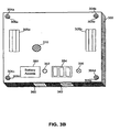
- FIGs. 3A and 3B illustrate front-top and rear-bottom views, respectfully, of an exterior embodiment of a wireless, rugged, mobile data capture device.
- the wireless data capture device includes a durable sealed enclosure 302 designed to withstand the abuses of industrial environments.
- the durable enclosure 302 could be manufactured from a die cast metallic material, thixomolded metallic material, and injection molded plastic.
- the durable enclosure 302 is designed to withstand direct impacts, and shock loads due to the close proximity of the freight being transferred.
- the durable enclosure 302 is also sealed to prevent dust and water penetration.
- a wireless microprocessor 402 is mounted within the enclosure and coordinates the activity of the wireless, rugged, mobile data capture device and its described features.
- the wireless data capture device is capable of being mounted in close proximity to the freight being transferred. This includes being mounted at, or between the forks 106 on forklift 100, as illustrated in FIG. 1 .
- the wireless data capture device could alternatively be mounted on pallets jacks, hand trucks, conveyor belts, and any other type of industrial freight moving equipment.
- the durable sealed enclosure 302 therefore includes modular mounting means for securing the enclosure 302 and its hardware to industrial equipment such as forklift 100.
- the mounting means mitigates the effects of physical shock and vibration with the use of, for example, shock absorbing material, springs or other similar devices.
- the wireless data capture device uses a modular mounting concept constructed with standardized units or dimensions, thereby allowing flexibility and variety in use. This enables the device to be mounted on many different types of industrial equipment without the need for customizing, or changing the wireless data capture device.
- the mounting means could include a simple nut and bolt arrangement passed through holes 304a-d for securing the durable enclosure 302 to industrial equipment, as illustrated in FIGS. 3A-B .
- Such an arrangement would ideally have shock mounting features such as insulating rubber vibration pads 306a-d, as shown in FIG. 3B .
- the modular mounting means could be a simple tongue-and-groove mounting plate or bracket arrangement 305a-b, which would include corresponding mating parts on the industrial equipment.
- the mounting means may also use a mounting cradle (not shown) into which the durable sealed enclosure 302 rests. The skilled artisan could envision a variety of modular mounting techniques.
- a communications antenna 202 is mounted proud (e.g., extending outward, not flush) on the durable sealed enclosure 302 and is communicatively coupled to a wireless microprocessor of the mobile data capture device.
- the communications antenna 202 could also be flush-mounted on durable enclosure 302, or internally mounted for increased ruggedness and to reduce likelihood of damage in an industrial environment.
- Communications antenna 202 is ideally a multi-purpose antenna that permits wireless communication with a remote communications network.
- the remote communications network may be a wide area network (WAN), a local area network (LAN), a personal area network (PAN), or even a global positioning system (GPS) network.
- WAN wide area network
- LAN local area network
- PAN personal area network
- GPS global positioning system
- the durable sealed enclosure 302 also permits wired communication with a wireless microprocessor mounted therein.
- a wired connection 352 when present, permits connection to a coaxial communications cable
- a wired connection 354 when present supports a number of universal system bus (USB), Ethernet, or Firewire connections.
- the front side of the durable sealed enclosure may also include a keypad and display 345 for direct communication with the wireless microprocessor mounted within.
- Other illustrated features include a proximity or motion detector 330, and a manual on/off switch 335.
- FIG. 3A illustrates an RFID antenna assembly 120.
- the features of the RFID antenna assembly 120 are described more fully below.
- the RFID antenna assembly 120 can be mounted proud of the external surface of the durable, sealed enclosure 302, or could be mounted flush with the external surface.
- An external flush mounted antenna capable of with standing high impact loads is preferred.
- External RFID antenna connectors may also be provided to allow the wireless data capture device 110 to use several externally mounted antennas if required for unique applications.
- the RFID antenna assembly 120 could be mounted within the durable sealed enclosure 302, wherein the enclosure permits the transmission and reception of RFID signals.
- data capture devices could be installed, such as a laser scanner device, an optical imager device, or an infra-red data association (IRDA) device.
- IRDA infra-red data association
- Such data capture devices could be mounted externally to the durable enclosure 302 and communicatively coupled to the wireless microprocessor.
- data capture devices could be integrated with the durable sealed enclosure, in which case the durable sealed enclosure 302 would be configured to permit the transmission and reception of the appropriate data signal--e.g., infra-red data, visible light, or laser light.
- the back side of durable sealed enclosure 302 may also include an audio speaker 370, a battery access panel 380, and an external power supply connection 356. Furthermore, and as illustrated in more detail below, the durable sealed enclosure 302 may include a set of make-or-break contacts 360 or a wireless inductive contact 362 for battery charging operations. Power supply and management features are more fully described below.
- FIGs. 3A-B serve to illustrate some of the preferred features of the wireless, rugged, mobile data capture device.
- the placement of the features in FIGs. 3A-B is not, however, intended to be limiting, and the skilled artisan could easily conceive and implement alternate locations for each described feature.
- each feature or device is coupled to and interacts with the wireless microprocessor mounted within the durable sealed enclosure 302 through device-appropriate couplings. Further details of the described features are illustrated more fully below with respect to FIG. 4 .
- FIG. 4 illustrates a block diagram of the interior of the wireless, rugged, mobile data capture device 110.
- FIG. 4 is not intended to be limiting, but rather is intended to illustrate the various features that have been incorporated into the wireless, rugged, mobile data capture device 110.
- a wireless microprocessor 402. This onboard wireless computer can be shock mounted within the sealed durable enclosure 302 with shock absorbing material, springs 430a-b or the like.
- Wireless microprocessor 402 could be one of numerously available commercial microprocessors such as Qualcomm's 1GHz SCORPIONTM mobile microprocessor, or one of Intel's CENTRINOTM platforms that include, for example, WiMax capabilities.
- the wireless data capture device and integrated RFID reader 220 can be used in conjunction with other devices such as handheld computers, fix mounted forklift or handtruck computers, barcode scanners, etc. via wired or wireless communication network connections.
- a wireless communications module (including wireless microprocessor 402) may be configured to communicate according to WLAN (e.g., IEEE 802.11) and/or BLUETOOTH (e.g., IEEE 802.15) standards.
- the wireless communications module may communicate with an access point located elsewhere on forklift 100 or located external to forklift 100.
- wireless, rugged, mobile data capture device 110 is a power supply system 406 and a power management system 418.
- power may be supplied by a battery 409, or by an external power source provided from, for example, forklift 100.
- the battery 409 may be a rechargeable battery, a removable battery, or both.
- a power supply bus 407 is coupled to power supply system 406 and distributes power throughout the wireless, rugged, mobile data capture device 110. Details of the power management system 418 and power supply options and features are described in more detail below.
- FIG. 4 Other features illustrated in FIG. 4 include a global positioning satellite (GPS) receiver 416, an audio circuit 412, both of which are coupled to the wireless microprocessor 402. Additionally, there is a wired communications bus 410 that is disposed between the plurality of wired communications connections 352, 354 and the wireless microprocessor 402.
- GPS global positioning satellite
- the power supply system 406 may include a battery 409 and a battery charging circuit 408.
- the power supply system 406 receives power for charging the battery 409 from an external power connector.
- the durable sealed enclosure 302 could include external charging contacts consisting of make-or-break electromechanical contacts 360 or an internal inductive coupling 362.
- the external power connection could be a traditional cable connector 356.
- the battery 409 may be charged while in the rugged, wireless, data capture device 110 via one of the described external power connectors and battery charging circuit 408. Alternatively, it could be removed and charged in standard charging accessories.
- the wireless data capture device 110 is also capable of communicating with an external battery-charging accessory (not shown). Such communication would enable an external battery-charging accessory to monitor the state of charge of the removable, rechargeable battery 409 in the wireless data capture device 110, and adjust its charge accordingly. For example, if the removable, rechargeable battery 409 in the wireless data capture device 110 were at a low state, and a corresponding removable, rechargeable battery 409 in the external charging accessory was not at a full charge, the wireless data capture device 110 could send a signal to the external charging accessory directing it to increase the rate of charge for the battery in the external charging accessory such that it would be fully charged when the battery 409 was fully discharged and ready to be changed.
- the external battery-charging accessory could be wired and mounted to the same forklift 100 as the rugged, wireless, data capture device 110.
- the battery 409 could also be directly charged from the freight moving equipment to which it is mounted, i.e., forklift truck, pallet jack, etc.
- the power supply system 406 could be wired directly to the external charging contacts consisting of make-or-break electromechanical contacts 360 or an internal inductive coupling 362.
- the power supply system 406 could be wired directly to the external traditional cable connector 356.
- the external power connections 356, 360, 362 could be integrated into the modular mounting system.
- the forklift 100 could have corresponding wired charging contacts fixed to a mounting plate (not shown) located at the base of the forklift 100.
- the rugged, wireless, data capture device 100 would be installed at the forks for maximum system read performance, and would move up and down with the freight.
- the wireless data capture device 110 external charging contacts Upon lowering the forks to the down position (normal forklift operate and drive position), the wireless data capture device 110 external charging contacts would make contact with the corresponding forklift charging contacts located on the fixed mounting plate (not shown) at the base of the forklift 100.
- a mounting cradle (not shown) could be mounted and wired to the forklift 100.
- the wireless data capture device would be placed and retained by the mounting cradle.
- the mounting cradle utilizes charging contacts that would interface with the wireless data capture device external charging contacts.
- the external charging contacts on the forklift 100 and rugged, wireless data capture device could be classic electro-mechanical contacts (plated cantilever beams, coil, pogo-pins, torsional, pads, male/female, etc.), or they could be inductive type contacts inlayed within the housing and charging structure.
- a number of power management techniques for enhanced battery life can be employed by the rugged, wireless data capture device 110. These include, but are not limited to using a predetermined duty cycle, a proximity sensor, motion sensor or other automatic or manual triggering mechanisms.
- a proximity or motion sensor 330 could be integrated with the sealed, durable, enclosure 302 as illustrated in FIG. 3A .
- the system would have the capability to shut various systems off and on to conserve battery power.
- the RFID radio could be shut off and on based on a predetermined time interval, while still maintaining a robust system read capability.
- the wireless data capture device 110 could be in a sleep mode until something is put in its path at a predetermined minimum range. For example, the unit is in sleep mode until the forklift 100 got within two feet of a pallet loaded with freight, at which occurrence the unit would enter an awake mode. After the wireless data capture device 110 was turned on to read the appropriate tags, it would go back into sleep mode until the pallet or freight was off-loaded. The decoupling of the proximity sensor would turn the unit back on, reading the appropriate tags again, confirming that the freight was dropped off.
- the proximity sensor could be based on any switch technology, i.e., IR, sonic, optical, etc.
- the wireless data capture device 110 could be in sleep mode until motion was detected. Upon not sensing motion for a predetermined period of time, the wireless data capture device 110 would go back into sleep mode.
- the motion sensor can be based on, but not limited to; switch, accelerometer, strain gage, piezo, and MEMs technologies, including combinations of the like.
- the wireless data capture device 110 could also incorporate triggering functions based upon the specific user applications.
- the wireless data capture device 110 could have its reader turn on and off by having the user manually trigger the device only when interested in reading tags. For example, when the forklift operator picks up a pallet, the device is triggered. When the pallet is moved and put in another location, the device is triggered again.
- This manual trigger could be from any remote device working on the network, i.e., a hand-held computer, a vehicle mounted computer, a remote control, etc.
- the manual trigger could be a wired trigger or a wireless trigger.
- An important feature of the wireless, rugged, mobile data capture device 110 with an integrated RFID reader 220 is its associated RFID antenna assembly 120.
- An exemplary RFID antenna is described in the co-pending U.S. Patent Application No. 11/265,143, filed November 3, 2005 , entitled “Low Return Loss Rugged RFID Antenna,” (“the '143 application”) which is hereby incorporated by reference in its entirety. Some RFID antenna considerations are discussed next.
- antennas such as patch antennas, cavity-backed patch antennas, inverted-F antennas, monopoles, dipoles, and Yagi antennas.
- VSWR voltage standing wave ratio
- a 2:1 VSWR equates to a return loss of -9.54 dB, and represents a worse case transmission loss of -0.51 dB.
- an antenna VSWR of 1.5:1 has been specified, which equates to a return loss of -14 dB, and a worse case transmission loss of -0.18 dB.
- a new set of requirements is being introduced for RFID device antennas, including return losses of -20 to -30 dB, which equates to a VSWR of 1.22 to 1.065, respectively, across a frequency band of interest (often 902 to 928 MHz).
- This new requirement is not necessarily for the purpose of maintaining transmission efficiency, but is present to avoid saturation of RFID receivers that can occur when a return loss above -20 dB is present.
- the present invention is directed to a wireless, rugged, mobile data capture device 110 whose integrated RFID reader 220 is used in environments that can be highly physically abusive to the antenna.
- an antenna that has been carefully tuned to provide an acceptable performance will usually degrade in performance, due to the physical abuse and damage that can result from impacts to the antenna by objects being transported by, or crushed within, these types of machinery.
- Antennas may be protected by placing them within a transparent radome, which can withstand impacts.
- this technique requires compromise between the physical strength and the RF transparency of radomes, as well as the disadvantage of added antenna size, including thickness, caused by the radome. Many of these problems are ameliorated in the above incorporated '143 application.
- a further difficulty occurs when an RFID tag resides in an environment having large, RF-reflective objects.
- the reflective objects can create a strong signal return to the RFID reader as a reflection of a reader transmitted signal. This can make the reader susceptible to false tag responses, and/or can mask tag responses, because of the presence of the intermodulation distortion (IMD) products created within the receiver when multiple signals are present in the environment (due to the external reflections).
- IMD intermodulation distortion
Landscapes
- Engineering & Computer Science (AREA)
- Artificial Intelligence (AREA)
- Computer Vision & Pattern Recognition (AREA)
- Physics & Mathematics (AREA)
- General Physics & Mathematics (AREA)
- Theoretical Computer Science (AREA)
- Mobile Radio Communication Systems (AREA)
- Transceivers (AREA)
- Forklifts And Lifting Vehicles (AREA)
- Radar Systems Or Details Thereof (AREA)
- Near-Field Transmission Systems (AREA)
- Support Of Aerials (AREA)
Claims (15)
- Robuste, mobile, drahtlose Datenerfassungsvorrichtung (110), die Folgendes aufweist: ein beständiges, abgedichtetes Gehäuse (302); einen drahtlosen Mikroprozessor (402), der innerhalb des Gehäuses angebracht ist; eine Funkfrequenzidentifikationslesevorrichtung (220), die mit dem drahtlosen Mikroprozessor gekoppelt ist und innerhalb des Gehäuses angebracht ist; eine Funkfrequenzidentifikationsantennenanordnung (120), die kommunikativ mit der Datenerfassungsvorrichtung gekoppelt ist; eine Kommunikationsantenne (202), die an dem Gehäuse angebracht ist und kommunikativ mit dem drahtlosen Mikroprozessor gekoppelt ist; ein Leistungsliefersystem (406), das Leistung an die Datenerfassungsvorrichtung liefert; und Anbringungsmittel (430) zum Befestigen des Gehäuses an einem industriellen Ausrüstungsgegenstand, und zwar in einer solchen Art und Weise, dass die Wirkungen physischer Stöße und Vibrationen abgeschwächt werden;
wobei die Vorrichtung dadurch Folgendes gekennzeichnet ist, dass:die Funkfrequenzidentifikationsantennenanordnung (120) auf einer Außenoberfläche des Gehäuses (302) angebracht ist. - Vorrichtung gemäß Anspruch 1, die ferner eine Laserscannervorrichtung (120) umfasst, die kommunikativ mit dem drahtlosen Mikroprozessor gekoppelt und innerhalb des Gehäuses angebracht ist, wobei das Gehäuse so konfiguriert ist, dass es die Übertragung und den Empfang des Laserlichts durch die Laserscannervorrichtung zulässt.
- Vorrichtung gemäß Anspruch 1, die ferner eine optische Bildgerätvorrichtung (120) umfasst, die kommunikativ mit dem drahtlosen Mikroprozessor gekoppelt und innerhalb des Gehäuses angebracht ist, wobei das Gehäuse so konfiguriert ist, dass es die Übertragung und den Empfang des sichtbaren Lichts durch die optische Bildgerätvorrichtung zulässt.
- Vorrichtung gemäß Anspruch 1, die ferner einen IrDA-kompatiblen (IrDA = Infrared Data Association) Sendeempfänger bzw. Transceiver (120) umfasst, der mit dem drahtlosen Mikroprozessor gekoppelt und innerhalb des Gehäuses angebracht ist, wobei das Gehäuse so konfiguriert ist, dass es die Übertragung und den Empfang des Infrarotlichts durch den IrDA-kompatiblen Transceiver zulässt.
- Vorrichtung gemäß Anspruch 1, wobei der drahtlose Mikroprozessor (402) drahtlos mit einem Fernkommunikationsnetzwerk kommuniziert.
- Vorrichtung gemäß Anspruch 1, wobei das Stromversorgungssystem ferner durch Folgendes gekennzeichnet ist: eine Batterieladeschaltung (408); eine wiederaufladbare Batterie (409), die entfernbar mit der Batterieladeschaltung gekoppelt ist; ein Verbindungsmittel (407) zu einer externen Stromversorgung; und ein Leistungsverwaltungssystem (418), das mit dem Stromversorgungssystem gekoppelt ist, das die Leistungsverteilung an die verschiedenen Komponenten der drahtlosen Datenerfassungsvorrichtung reguliert.
- Vorrichtung gemäß Anspruch 6, wobei das Leistungsverwaltungssystem (418) kommunikativ mit einem externen Batterieladezubehör gekoppelt ist, das den Ladezustand überwacht und die Ladungsrate einer entfernbaren, wiederaufladbaren Ersatzbatterie gemäß Anweisungen durch das Leistungsverwaltungssystem anpasst.
- Vorrichtung gemäß Anspruch 6, wobei das Leistungsverwaltungssystem (418) mit einem Näherungssensor gekoppelt ist, wobei verschiedene Datenerfassungsvorrichtungskomponenten an- und abgeschaltet werden, und zwar abhängig von der Lage der Fracht oder anderer Gegenstände, die Informationen aufweisen, die erfasst werden sollen.
- Vorrichtung gemäß Anspruch 6, wobei das Leistungsverwaltungssystem (418) mit einem Bewegungssensor gekoppelt ist, der es erlaubt dass verschiedene Datenerfassungsvorrichtungskomponenten an- oder ausgeschaltet werden, und zwar abhängig von der Bewegung der drahtlosen Datenerfassungsvorrichtung.
- Vorrichtung gemäß Anspruch 1, wobei die drahtlose Datenerfassungsvorrichtung (110) einen manuellen Auslöser zum An- und ausschalten der drahtlosen Datenerfassungsvorrichtung umfasst.
- Vorrichtung gemäß Anspruch 1, wobei die Antennen (202, 120) der drahtlosen Datenerfassungsvorrichtung bündig mit einer Außenoberfläche des beständigen, abgedichteten Gehäuses angebracht sind.
- Vorrichtung gemäß Anspruch 1, wobei die Kommunikationsantenne (202) der drahtlosen Datenerfassungsvorrichtung innerhalb des beständigen, abgedichteten Gehäuses angebracht ist, wobei das Gehäuse die Übertragung und den Empfang der Signale zulässt.
- Vorrichtung gemäß Anspruch 1, wobei die Antennen (202, 120) der drahtlosen Kommunikationsvorrichtung aus der Außenoberfläche des beständigen, abgedichteten Gehäuses herausragend angebracht sind.
- Vorrichtung gemäß Anspruch 1, wobei die drahtlose Datenerfassungsvorrichtung (110) Außenantennenanschlüsse umfasst, die die Verwendung von externen, verdrahteten Antennen unterstützen.
- Vorrichtung gemäß Anspruch 1, wobei die Anbringungsmittel (430) externe oder interne Vibrations- / Stoßlager umfassen, die mit dem beständigen, abgedichteten Gehäuse und der internen Elektronik gekoppelt sind.
Applications Claiming Priority (2)
| Application Number | Priority Date | Filing Date | Title |
|---|---|---|---|
| US11/410,964 US7504948B2 (en) | 2006-04-26 | 2006-04-26 | Wireless rugged mobile data capture device with integrated RFID reader |
| PCT/US2007/009877 WO2007127180A2 (en) | 2006-04-26 | 2007-04-24 | Wireless rugged mobile data capture device with integrated rfid reader |
Publications (3)
| Publication Number | Publication Date |
|---|---|
| EP2011095A2 EP2011095A2 (de) | 2009-01-07 |
| EP2011095A4 EP2011095A4 (de) | 2010-12-29 |
| EP2011095B1 true EP2011095B1 (de) | 2012-02-08 |
Family
ID=38647803
Family Applications (1)
| Application Number | Title | Priority Date | Filing Date |
|---|---|---|---|
| EP07776049A Active EP2011095B1 (de) | 2006-04-26 | 2007-04-24 | Robustes drahtloses datenerfassungsgerät mit integriertem rfid-leser |
Country Status (5)
| Country | Link |
|---|---|
| US (1) | US7504948B2 (de) |
| EP (1) | EP2011095B1 (de) |
| CN (1) | CN101460982A (de) |
| AT (1) | ATE545096T1 (de) |
| WO (1) | WO2007127180A2 (de) |
Families Citing this family (24)
| Publication number | Priority date | Publication date | Assignee | Title |
|---|---|---|---|---|
| JP2007304666A (ja) * | 2006-05-08 | 2007-11-22 | Sony Computer Entertainment Inc | 情報出力システム及び情報出力方法 |
| US7761115B2 (en) * | 2006-05-30 | 2010-07-20 | Broadcom Corporation | Multiple mode RF transceiver and antenna structure |
| FR2905493B1 (fr) * | 2006-08-31 | 2008-12-05 | Nbg Id Soc Par Actions Simplif | Systeme automatise de realisation d'inventaires localises |
| US8199004B1 (en) * | 2006-09-29 | 2012-06-12 | Ncr Corporation | RFID tag reader |
| US7982776B2 (en) * | 2007-07-13 | 2011-07-19 | Ethicon Endo-Surgery, Inc. | SBI motion artifact removal apparatus and method |
| US9108434B2 (en) * | 2007-12-18 | 2015-08-18 | Zih Corp. | RFID near-field antenna and associated systems |
| US20110090846A1 (en) * | 2008-04-24 | 2011-04-21 | Visible Assets, Inc. | Portable Access Point |
| US7743997B2 (en) * | 2008-05-21 | 2010-06-29 | Sensormatic Electronics, Llc. | Handheld combination bar code and RFID reader with integrated electronics and antenna |
| US20090309704A1 (en) * | 2008-06-11 | 2009-12-17 | Symbol Technologies, Inc. | Methods and Systems for RFID Reader Power Management |
| WO2010008620A1 (en) * | 2008-07-15 | 2010-01-21 | Syntag Mfg.Llc | Durable rfid tag |
| US8188863B2 (en) * | 2008-11-26 | 2012-05-29 | Symbol Technologies, Inc. | Detecting loading and unloading of material |
| DE102009034975A1 (de) * | 2009-07-28 | 2011-02-03 | Still Gmbh | Flurförderzeug mit Datenerfassungsvorrichtung |
| US8350675B2 (en) | 2010-04-30 | 2013-01-08 | Symbol Technologies, Inc. | Triggering a radio frequency identification scan using image recognition |
| US8614963B2 (en) | 2010-06-15 | 2013-12-24 | Silverplus, Inc. | Wireless system protocols for power-efficient implementation of star and mesh wireless networks with local and wide-area coverage |
| DE102011089346B4 (de) | 2011-12-21 | 2021-12-23 | Endress+Hauser SE+Co. KG | Verfahren zum Betreiben eines Feldgerätes der Prozessautomatisierungstechnik |
| US8976030B2 (en) | 2012-04-24 | 2015-03-10 | Metrologic Instruments, Inc. | Point of sale (POS) based checkout system supporting a customer-transparent two-factor authentication process during product checkout operations |
| US9041340B2 (en) * | 2013-02-21 | 2015-05-26 | Wayne M Spani | Systems and methods for in-vehicle charging of pallet jack batteries |
| CN103411663B (zh) * | 2013-07-29 | 2015-06-10 | 中国矿业大学 | 一种带式输送机噪声采集系统 |
| US9547079B2 (en) | 2014-02-06 | 2017-01-17 | Fedex Corporate Services, Inc. | Object tracking method and system |
| US10243254B2 (en) | 2016-08-25 | 2019-03-26 | Schlage Lock Company Llc | Self adjusting antenna impedance for credential detection in an access control system |
| CN107274620A (zh) * | 2017-07-27 | 2017-10-20 | 成都巨盛科技有限公司 | 借阅室的防盗设备 |
| US10618735B1 (en) | 2019-03-11 | 2020-04-14 | Coupang Corp. | Computerized systems and methods for assisted picking processes |
| CN111432335B (zh) * | 2020-03-31 | 2021-11-23 | 吉林工程技术师范学院 | 一种国际贸易港口用系统的控制方法 |
| US12151094B2 (en) | 2021-01-27 | 2024-11-26 | Neurostim Technologies Llc | Non-invasive nerve stimulator with battery management |
Family Cites Families (10)
| Publication number | Priority date | Publication date | Assignee | Title |
|---|---|---|---|---|
| US6078251A (en) * | 1996-03-27 | 2000-06-20 | Intermec Ip Corporation | Integrated multi-meter and wireless communication link |
| US5804810A (en) * | 1996-06-26 | 1998-09-08 | Par Government Systems Corporation | Communicating with electronic tags |
| US5777561A (en) | 1996-09-30 | 1998-07-07 | International Business Machines Corporation | Method of grouping RF transponders |
| US6107910A (en) | 1996-11-29 | 2000-08-22 | X-Cyte, Inc. | Dual mode transmitter/receiver and decoder for RF transponder tags |
| US8229469B2 (en) * | 2004-03-15 | 2012-07-24 | Arbitron Inc. | Methods and systems for mapping locations of wireless transmitters for use in gathering market research data |
| US20050246248A1 (en) | 2004-04-30 | 2005-11-03 | Sarosh Vesuna | Mobile portal for radio frequency identification of objects |
| DE202005005409U1 (de) | 2005-04-06 | 2005-06-16 | Still Gmbh | Flurförderzeug mit einem Lastaufnahmemittel |
| US7460016B2 (en) * | 2005-05-13 | 2008-12-02 | Ems Technologies, Inc. | Radio frequency identification (RFID) system for a forklift |
| US20070109096A1 (en) * | 2005-09-08 | 2007-05-17 | Jeremy Breedlove | Global tracking and communications device |
| DE202005015095U1 (de) * | 2005-09-24 | 2006-01-19 | Jungheinrich Aktiengesellschaft | System zur Erkennung und Verwaltung von Paletten |
-
2006
- 2006-04-26 US US11/410,964 patent/US7504948B2/en active Active
-
2007
- 2007-04-24 CN CNA2007800208012A patent/CN101460982A/zh active Pending
- 2007-04-24 WO PCT/US2007/009877 patent/WO2007127180A2/en not_active Ceased
- 2007-04-24 EP EP07776049A patent/EP2011095B1/de active Active
- 2007-04-24 AT AT07776049T patent/ATE545096T1/de active
Also Published As
| Publication number | Publication date |
|---|---|
| WO2007127180A2 (en) | 2007-11-08 |
| EP2011095A4 (de) | 2010-12-29 |
| WO2007127180A3 (en) | 2008-09-12 |
| US20070252702A1 (en) | 2007-11-01 |
| US7504948B2 (en) | 2009-03-17 |
| ATE545096T1 (de) | 2012-02-15 |
| CN101460982A (zh) | 2009-06-17 |
| EP2011095A2 (de) | 2009-01-07 |
Similar Documents
| Publication | Publication Date | Title |
|---|---|---|
| EP2011095B1 (de) | Robustes drahtloses datenerfassungsgerät mit integriertem rfid-leser | |
| EP1966774B1 (de) | Robuste rfid-antenne mit geringem reflexionsverlust | |
| US20050200457A1 (en) | Inventory transport device with integrated RFID reader | |
| EP1886378B1 (de) | Sprossenangebrachte antenne für ein rfid-system | |
| US20060208893A1 (en) | Weight audit methods and systems utilizing data reader | |
| US7576657B2 (en) | Single frequency low power RFID device | |
| US20100176922A1 (en) | Mobile radio frequency identification (rfid) reader system | |
| WO2006124399A3 (en) | Antenna for mobile wireless data collection system | |
| US20060220872A1 (en) | Mounting bracket | |
| US20100001914A1 (en) | Antenna with improved illumination efficiency | |
| US8188863B2 (en) | Detecting loading and unloading of material | |
| US20060164251A1 (en) | Hand held RFID reader with dipole anthenna | |
| US7696875B2 (en) | Antenna interfaces for mobile RFID readers | |
| US20070290860A1 (en) | Apparatus, systems, and methods for tracking moving objects tagged with wireless tags | |
| US20070159331A1 (en) | System and method for saving battery power prior to deploying an asset tag | |
| US20080042846A1 (en) | Antenna for radio frequency identification systems | |
| KR102751050B1 (ko) | 무선 리드센서 및 이를 이용한 케이블리스 대차 관리 시스템 | |
| KR101569161B1 (ko) | 개선된 고주파수 안테나 | |
| JP2009290632A (ja) | Rfidタグ通信用床置アンテナおよびそれを用いたrfidリーダライタ | |
| CN105989454A (zh) | 货物装卸管理系统 | |
| CN102279920A (zh) | Rfid标签识别装置 | |
| KR20080004280U (ko) | 액티브 알에프 태그와 패시브 알에프 태그의 인식이 가능한일체형 알에프 리더기 | |
| US20100109871A1 (en) | Rfid system and method for the same |
Legal Events
| Date | Code | Title | Description |
|---|---|---|---|
| PUAI | Public reference made under article 153(3) epc to a published international application that has entered the european phase |
Free format text: ORIGINAL CODE: 0009012 |
|
| 17P | Request for examination filed |
Effective date: 20081023 |
|
| AK | Designated contracting states |
Kind code of ref document: A2 Designated state(s): AT BE BG CH CY CZ DE DK EE ES FI FR GB GR HU IE IS IT LI LT LU LV MC MT NL PL PT RO SE SI SK TR |
|
| AX | Request for extension of the european patent |
Extension state: AL BA HR MK RS |
|
| DAX | Request for extension of the european patent (deleted) | ||
| A4 | Supplementary search report drawn up and despatched |
Effective date: 20101129 |
|
| REG | Reference to a national code |
Ref country code: DE Ref legal event code: R079 Ref document number: 602007020597 Country of ref document: DE Free format text: PREVIOUS MAIN CLASS: G08B0013140000 Ipc: G06K0007000000 |
|
| GRAP | Despatch of communication of intention to grant a patent |
Free format text: ORIGINAL CODE: EPIDOSNIGR1 |
|
| RIC1 | Information provided on ipc code assigned before grant |
Ipc: G06K 7/00 20060101AFI20110912BHEP |
|
| GRAS | Grant fee paid |
Free format text: ORIGINAL CODE: EPIDOSNIGR3 |
|
| GRAA | (expected) grant |
Free format text: ORIGINAL CODE: 0009210 |
|
| AK | Designated contracting states |
Kind code of ref document: B1 Designated state(s): AT BE BG CH CY CZ DE DK EE ES FI FR GB GR HU IE IS IT LI LT LU LV MC MT NL PL PT RO SE SI SK TR |
|
| REG | Reference to a national code |
Ref country code: GB Ref legal event code: FG4D |
|
| REG | Reference to a national code |
Ref country code: AT Ref legal event code: REF Ref document number: 545096 Country of ref document: AT Kind code of ref document: T Effective date: 20120215 Ref country code: CH Ref legal event code: EP |
|
| REG | Reference to a national code |
Ref country code: DE Ref legal event code: R096 Ref document number: 602007020597 Country of ref document: DE Effective date: 20120405 |
|
| REG | Reference to a national code |
Ref country code: NL Ref legal event code: VDEP Effective date: 20120208 |
|
| LTIE | Lt: invalidation of european patent or patent extension |
Effective date: 20120208 |
|
| PG25 | Lapsed in a contracting state [announced via postgrant information from national office to epo] |
Ref country code: IS Free format text: LAPSE BECAUSE OF FAILURE TO SUBMIT A TRANSLATION OF THE DESCRIPTION OR TO PAY THE FEE WITHIN THE PRESCRIBED TIME-LIMIT Effective date: 20120608 Ref country code: LT Free format text: LAPSE BECAUSE OF FAILURE TO SUBMIT A TRANSLATION OF THE DESCRIPTION OR TO PAY THE FEE WITHIN THE PRESCRIBED TIME-LIMIT Effective date: 20120208 Ref country code: NL Free format text: LAPSE BECAUSE OF FAILURE TO SUBMIT A TRANSLATION OF THE DESCRIPTION OR TO PAY THE FEE WITHIN THE PRESCRIBED TIME-LIMIT Effective date: 20120208 |
|
| PG25 | Lapsed in a contracting state [announced via postgrant information from national office to epo] |
Ref country code: PT Free format text: LAPSE BECAUSE OF FAILURE TO SUBMIT A TRANSLATION OF THE DESCRIPTION OR TO PAY THE FEE WITHIN THE PRESCRIBED TIME-LIMIT Effective date: 20120608 Ref country code: GR Free format text: LAPSE BECAUSE OF FAILURE TO SUBMIT A TRANSLATION OF THE DESCRIPTION OR TO PAY THE FEE WITHIN THE PRESCRIBED TIME-LIMIT Effective date: 20120509 Ref country code: LV Free format text: LAPSE BECAUSE OF FAILURE TO SUBMIT A TRANSLATION OF THE DESCRIPTION OR TO PAY THE FEE WITHIN THE PRESCRIBED TIME-LIMIT Effective date: 20120208 Ref country code: BE Free format text: LAPSE BECAUSE OF FAILURE TO SUBMIT A TRANSLATION OF THE DESCRIPTION OR TO PAY THE FEE WITHIN THE PRESCRIBED TIME-LIMIT Effective date: 20120208 Ref country code: PL Free format text: LAPSE BECAUSE OF FAILURE TO SUBMIT A TRANSLATION OF THE DESCRIPTION OR TO PAY THE FEE WITHIN THE PRESCRIBED TIME-LIMIT Effective date: 20120208 Ref country code: FI Free format text: LAPSE BECAUSE OF FAILURE TO SUBMIT A TRANSLATION OF THE DESCRIPTION OR TO PAY THE FEE WITHIN THE PRESCRIBED TIME-LIMIT Effective date: 20120208 |
|
| REG | Reference to a national code |
Ref country code: AT Ref legal event code: MK05 Ref document number: 545096 Country of ref document: AT Kind code of ref document: T Effective date: 20120208 |
|
| PG25 | Lapsed in a contracting state [announced via postgrant information from national office to epo] |
Ref country code: CY Free format text: LAPSE BECAUSE OF FAILURE TO SUBMIT A TRANSLATION OF THE DESCRIPTION OR TO PAY THE FEE WITHIN THE PRESCRIBED TIME-LIMIT Effective date: 20120208 |
|
| PG25 | Lapsed in a contracting state [announced via postgrant information from national office to epo] |
Ref country code: RO Free format text: LAPSE BECAUSE OF FAILURE TO SUBMIT A TRANSLATION OF THE DESCRIPTION OR TO PAY THE FEE WITHIN THE PRESCRIBED TIME-LIMIT Effective date: 20120208 Ref country code: SE Free format text: LAPSE BECAUSE OF FAILURE TO SUBMIT A TRANSLATION OF THE DESCRIPTION OR TO PAY THE FEE WITHIN THE PRESCRIBED TIME-LIMIT Effective date: 20120208 Ref country code: DK Free format text: LAPSE BECAUSE OF FAILURE TO SUBMIT A TRANSLATION OF THE DESCRIPTION OR TO PAY THE FEE WITHIN THE PRESCRIBED TIME-LIMIT Effective date: 20120208 Ref country code: CZ Free format text: LAPSE BECAUSE OF FAILURE TO SUBMIT A TRANSLATION OF THE DESCRIPTION OR TO PAY THE FEE WITHIN THE PRESCRIBED TIME-LIMIT Effective date: 20120208 Ref country code: EE Free format text: LAPSE BECAUSE OF FAILURE TO SUBMIT A TRANSLATION OF THE DESCRIPTION OR TO PAY THE FEE WITHIN THE PRESCRIBED TIME-LIMIT Effective date: 20120208 Ref country code: SI Free format text: LAPSE BECAUSE OF FAILURE TO SUBMIT A TRANSLATION OF THE DESCRIPTION OR TO PAY THE FEE WITHIN THE PRESCRIBED TIME-LIMIT Effective date: 20120208 |
|
| PG25 | Lapsed in a contracting state [announced via postgrant information from national office to epo] |
Ref country code: IT Free format text: LAPSE BECAUSE OF FAILURE TO SUBMIT A TRANSLATION OF THE DESCRIPTION OR TO PAY THE FEE WITHIN THE PRESCRIBED TIME-LIMIT Effective date: 20120208 Ref country code: SK Free format text: LAPSE BECAUSE OF FAILURE TO SUBMIT A TRANSLATION OF THE DESCRIPTION OR TO PAY THE FEE WITHIN THE PRESCRIBED TIME-LIMIT Effective date: 20120208 Ref country code: MC Free format text: LAPSE BECAUSE OF NON-PAYMENT OF DUE FEES Effective date: 20120430 |
|
| REG | Reference to a national code |
Ref country code: CH Ref legal event code: PL |
|
| PLBE | No opposition filed within time limit |
Free format text: ORIGINAL CODE: 0009261 |
|
| STAA | Information on the status of an ep patent application or granted ep patent |
Free format text: STATUS: NO OPPOSITION FILED WITHIN TIME LIMIT |
|
| 26N | No opposition filed |
Effective date: 20121109 |
|
| REG | Reference to a national code |
Ref country code: IE Ref legal event code: MM4A |
|
| PG25 | Lapsed in a contracting state [announced via postgrant information from national office to epo] |
Ref country code: AT Free format text: LAPSE BECAUSE OF FAILURE TO SUBMIT A TRANSLATION OF THE DESCRIPTION OR TO PAY THE FEE WITHIN THE PRESCRIBED TIME-LIMIT Effective date: 20120208 Ref country code: LI Free format text: LAPSE BECAUSE OF NON-PAYMENT OF DUE FEES Effective date: 20120430 Ref country code: IE Free format text: LAPSE BECAUSE OF NON-PAYMENT OF DUE FEES Effective date: 20120424 Ref country code: CH Free format text: LAPSE BECAUSE OF NON-PAYMENT OF DUE FEES Effective date: 20120430 |
|
| REG | Reference to a national code |
Ref country code: DE Ref legal event code: R097 Ref document number: 602007020597 Country of ref document: DE Effective date: 20121109 |
|
| PG25 | Lapsed in a contracting state [announced via postgrant information from national office to epo] |
Ref country code: ES Free format text: LAPSE BECAUSE OF FAILURE TO SUBMIT A TRANSLATION OF THE DESCRIPTION OR TO PAY THE FEE WITHIN THE PRESCRIBED TIME-LIMIT Effective date: 20120519 |
|
| PG25 | Lapsed in a contracting state [announced via postgrant information from national office to epo] |
Ref country code: BG Free format text: LAPSE BECAUSE OF FAILURE TO SUBMIT A TRANSLATION OF THE DESCRIPTION OR TO PAY THE FEE WITHIN THE PRESCRIBED TIME-LIMIT Effective date: 20120508 Ref country code: MT Free format text: LAPSE BECAUSE OF FAILURE TO SUBMIT A TRANSLATION OF THE DESCRIPTION OR TO PAY THE FEE WITHIN THE PRESCRIBED TIME-LIMIT Effective date: 20120208 |
|
| PG25 | Lapsed in a contracting state [announced via postgrant information from national office to epo] |
Ref country code: TR Free format text: LAPSE BECAUSE OF FAILURE TO SUBMIT A TRANSLATION OF THE DESCRIPTION OR TO PAY THE FEE WITHIN THE PRESCRIBED TIME-LIMIT Effective date: 20120208 |
|
| PG25 | Lapsed in a contracting state [announced via postgrant information from national office to epo] |
Ref country code: LU Free format text: LAPSE BECAUSE OF NON-PAYMENT OF DUE FEES Effective date: 20120424 |
|
| PG25 | Lapsed in a contracting state [announced via postgrant information from national office to epo] |
Ref country code: HU Free format text: LAPSE BECAUSE OF FAILURE TO SUBMIT A TRANSLATION OF THE DESCRIPTION OR TO PAY THE FEE WITHIN THE PRESCRIBED TIME-LIMIT Effective date: 20070424 |
|
| REG | Reference to a national code |
Ref country code: FR Ref legal event code: PLFP Year of fee payment: 10 |
|
| REG | Reference to a national code |
Ref country code: DE Ref legal event code: R082 Ref document number: 602007020597 Country of ref document: DE Representative=s name: LKGLOBAL | LORENZ & KOPF PARTG MBB PATENTANWAE, DE Ref country code: DE Ref legal event code: R082 Ref document number: 602007020597 Country of ref document: DE Representative=s name: SCHUMACHER & WILLSAU PATENTANWALTSGESELLSCHAFT, DE Ref country code: DE Ref legal event code: R081 Ref document number: 602007020597 Country of ref document: DE Owner name: SYMBOL TECHNOLOGIES, LLC (N.D. GES. D. STAATES, US Free format text: FORMER OWNER: SYMBOL TECHNOLOGIES, INC., HOLTSVILLE, N.Y., US Ref country code: DE Ref legal event code: R082 Ref document number: 602007020597 Country of ref document: DE Representative=s name: KOPF, KORBINIAN, DIPL.-ING.UNIV., MA, DE |
|
| REG | Reference to a national code |
Ref country code: DE Ref legal event code: R082 Ref document number: 602007020597 Country of ref document: DE Representative=s name: LKGLOBAL | LORENZ & KOPF PARTG MBB PATENTANWAE, DE Ref country code: DE Ref legal event code: R082 Ref document number: 602007020597 Country of ref document: DE Representative=s name: KOPF, KORBINIAN, DIPL.-ING.UNIV., MA, DE |
|
| REG | Reference to a national code |
Ref country code: FR Ref legal event code: PLFP Year of fee payment: 11 |
|
| REG | Reference to a national code |
Ref country code: DE Ref legal event code: R082 Ref document number: 602007020597 Country of ref document: DE Representative=s name: LKGLOBAL | LORENZ & KOPF PARTG MBB PATENTANWAE, DE |
|
| REG | Reference to a national code |
Ref country code: FR Ref legal event code: CA Effective date: 20171120 Ref country code: FR Ref legal event code: CD Owner name: SYMBOL TECHNOLOGIES, INC., US Effective date: 20171120 Ref country code: FR Ref legal event code: CJ Effective date: 20171120 |
|
| REG | Reference to a national code |
Ref country code: FR Ref legal event code: PLFP Year of fee payment: 12 |
|
| P01 | Opt-out of the competence of the unified patent court (upc) registered |
Effective date: 20230416 |
|
| PGFP | Annual fee paid to national office [announced via postgrant information from national office to epo] |
Ref country code: FR Payment date: 20250319 Year of fee payment: 19 |
|
| PGFP | Annual fee paid to national office [announced via postgrant information from national office to epo] |
Ref country code: GB Payment date: 20250319 Year of fee payment: 19 |
|
| PGFP | Annual fee paid to national office [announced via postgrant information from national office to epo] |
Ref country code: DE Payment date: 20250319 Year of fee payment: 19 |