EP2010867B1 - Sensor for a measuring point and method for inspecting a sensor for a measuring point - Google Patents
Sensor for a measuring point and method for inspecting a sensor for a measuring point Download PDFInfo
- Publication number
- EP2010867B1 EP2010867B1 EP07728076.6A EP07728076A EP2010867B1 EP 2010867 B1 EP2010867 B1 EP 2010867B1 EP 07728076 A EP07728076 A EP 07728076A EP 2010867 B1 EP2010867 B1 EP 2010867B1
- Authority
- EP
- European Patent Office
- Prior art keywords
- sensor head
- sensor
- measuring point
- control system
- data
- Prior art date
- Legal status (The legal status is an assumption and is not a legal conclusion. Google has not performed a legal analysis and makes no representation as to the accuracy of the status listed.)
- Active
Links
- 238000000034 method Methods 0.000 title claims description 13
- 238000004891 communication Methods 0.000 claims description 26
- 238000012360 testing method Methods 0.000 claims description 18
- 230000005540 biological transmission Effects 0.000 claims description 8
- 238000005516 engineering process Methods 0.000 claims description 6
- 101150093044 SVF1 gene Proteins 0.000 claims description 3
- 230000000694 effects Effects 0.000 claims description 3
- 238000005259 measurement Methods 0.000 description 6
- 230000004044 response Effects 0.000 description 6
- 238000012545 processing Methods 0.000 description 4
- 238000004140 cleaning Methods 0.000 description 2
- 238000003780 insertion Methods 0.000 description 2
- 230000037431 insertion Effects 0.000 description 2
- 238000009434 installation Methods 0.000 description 2
- 238000004801 process automation Methods 0.000 description 2
- XFXPMWWXUTWYJX-UHFFFAOYSA-N Cyanide Chemical compound N#[C-] XFXPMWWXUTWYJX-UHFFFAOYSA-N 0.000 description 1
- 238000011109 contamination Methods 0.000 description 1
- 230000008878 coupling Effects 0.000 description 1
- 238000010168 coupling process Methods 0.000 description 1
- 238000005859 coupling reaction Methods 0.000 description 1
- 238000010586 diagram Methods 0.000 description 1
- 238000011156 evaluation Methods 0.000 description 1
- 230000001939 inductive effect Effects 0.000 description 1
- 239000007788 liquid Substances 0.000 description 1
- 238000012423 maintenance Methods 0.000 description 1
- 238000004519 manufacturing process Methods 0.000 description 1
- 238000001139 pH measurement Methods 0.000 description 1
- 238000000926 separation method Methods 0.000 description 1
- 238000004088 simulation Methods 0.000 description 1
- 238000010998 test method Methods 0.000 description 1
- 238000012795 verification Methods 0.000 description 1
Images

Classifications
-
- G—PHYSICS
- G01—MEASURING; TESTING
- G01D—MEASURING NOT SPECIALLY ADAPTED FOR A SPECIFIC VARIABLE; ARRANGEMENTS FOR MEASURING TWO OR MORE VARIABLES NOT COVERED IN A SINGLE OTHER SUBCLASS; TARIFF METERING APPARATUS; MEASURING OR TESTING NOT OTHERWISE PROVIDED FOR
- G01D21/00—Measuring or testing not otherwise provided for
-
- H—ELECTRICITY
- H03—ELECTRONIC CIRCUITRY
- H03K—PULSE TECHNIQUE
- H03K2217/00—Indexing scheme related to electronic switching or gating, i.e. not by contact-making or -breaking covered by H03K17/00
- H03K2217/94—Indexing scheme related to electronic switching or gating, i.e. not by contact-making or -breaking covered by H03K17/00 characterised by the way in which the control signal is generated
- H03K2217/94084—Transmission of parameters among sensors or between sensor and remote station
- H03K2217/94089—Wireless transmission
Definitions
- the invention relates to a sensor for a measuring point and method for checking a sensor for a measuring point.
- sensors are often used to record measured values.
- the sensors are connected via a transmitter to a control system, to which the measured data are forwarded.
- the communication between the transducers and the control system takes place according to one of the standard in process automation technology standards, such.
- B. HART data transmission or a fieldbus system Fluorescence Fielbus, Profibus, etc.
- proprietary protocols are sometimes used in digital data transmission, especially with peer-to-peer connections between the sensor and the transmitter.
- the sensors are often composed of two components, a sensor head and a matching sensor head counterpart.
- the provided at a measuring point sensor head counterpart is firmly connected to the transmitter, the sensor head can be removed. This division is particularly advantageous in sensors that need to be maintained regularly.
- the sensor head can simply be removed at the measuring point to be transported to a laboratory where maintenance is performed.
- Such a two-part sensor offers the applicant (Endress + Hauser Conducta) under the product name Memosens®. This product has long been manufactured and distributed by the Applicant.
- the problem with such sensors is that after cleaning or after calibrating the correct sensor head is used again at the right measuring point with the sensor head counterpart. Often, the user will carry a box containing a set of multiple sensor heads from which to select the correct sensor head for that particular site. To do this, the sensor heads are labeled with the tag name (TAG name) to make it easier for the user to assign the sensor head tag.
- TAG name the tag name
- An incorrectly inserted measuring head can, for. B. lead to contamination of the product to be measured and thus affect subsequent processing steps of the product sensitive.
- sensors should also be able to be connected directly to the control system without the interposition of a transmitter.
- An incorrectly inserted sensor head can in principle be displayed on the transmitter or on the control system.
- WO2005031339 A1 describes a liquid or gas sensor, which is built from a sensor module and a sensor module head, which are pluggable connectable to each other and allow in the assembled state, a data and energy exchange via a galvanically decoupled transmission path.
- a plug-in module is provided which can be connected to the sensor module or the sensor module head and serves for the display of sensor data stored in the sensor module or for the simulation of a measured value.
- the object of the invention is therefore to provide a sensor for a measuring point and a method for checking a sensor for a measuring point, which or does not have the disadvantages mentioned above, in particular a secure exchange of measuring heads is ensured at Sensorn and the user an error gets signaled immediately when inserting a wrong sensor head.
- a control system L is shown, which is connected to a plurality of sensors T1, T2, T3 via corresponding cables K1, K2, K3.
- the sensors T1, T2, T3 are each associated with corresponding measuring points M1, M2, M3.
- the communication between the sensor and the control system takes place via a serial data communication with a "physical layer" according to the RS 485 standard.
- actuators are connected.
- the control system L can be a PLC unit (programmable logic controller) or a decentralized controller DCS (distributed control system).
- the control system L is also connected to a local network (Ethernet), which enables system / company-wide data exchange.
- a block diagram of a sensor according to the invention is shown, which consists of two components, a sensor head SK and a sensor head counterpart SG. These two components are connected to each other via an easy-to-solve bayonet fitting.
- the sensor head SK consists essentially of a sensor MA, which is used to detect a physical quantity z. As pH, temperature, etc. is used.
- the sensor MA is followed by an analog signal processing unit SV, in which the analog measurement signal preprocessed z. B. filtered or amplified.
- an analog / digital converter A / D 1 the measurement signal is fed to a microcontroller ⁇ C1, in which further processing of the measurement signal takes place.
- the microcontroller ⁇ C1 can send and receive data.
- the communication interface S1 consists of a converter W1 and a power supply unit SVSK and a coil L1.
- a sensor head counterpart SG is formed. Both are connected to one another via a bayonet connection, not shown, easily detachable.
- the sensor head counterpart SG has a counterpart S1, which corresponds to the communication interface S1, the communication interface S2.
- This consists of a coil L2 an amplifier V and a converter W2.
- the converter W2 is connected to a microcontroller ⁇ C2.
- the communication with the control system L is wired via a communication interface S3, the z. B. consists of a RS-485 module.
- the cable K has 4 lines LG1, LG2, LG3, LG4, which are surrounded by a shield AS. Two wires are for communication and two wires for power transmission to Sensor head counterpart SG provided.
- a power supply unit SVE For the power supply of the sensor head counterpart SG is a power supply unit SVE, which is supplied via the lines LG1 and LG2 from the control system L from.
- the data transmission between the two communication interfaces S1 and S2 takes place via an inductive coupling.
- energy is transmitted wirelessly to the sensor head SK via this connection.
- This energy is converted in the power supply unit SVSK and converted into a corresponding supply voltage for the individual components.
- various measurement data, parameterization data and sensor-specific data are transmitted, e.g. Sensor identification with serial number, production date, hardware and software version, measured values with main measurement and secondary measurement (i.d.R temperature), calibration data with offset / slope, date / time, calibration method, sensor state with duration of use under extreme conditions, calibration cycles, auxiliary parameters for condition evaluation,
- Information about the measuring point such as TAG number
- information on the sensor element on the sensor head such as measuring range, initial startup, batch.
- sensor head SK and sensor head counterpart SG are completely galvanically separated. This galvanic separation is particularly advantageous in the pH measurement, but not necessarily required for the present invention.
- the sensor head SK is unscrewed from the sensor head counterpart SG and transported to a laboratory remote from the measuring point M1, where the actual calibration takes place. This can be done automatically and the calibration values for each sensor head are stored uniquely assignable in a database.
- This database can, for. B. also be connected to the local network. Then the sensor head has to be replaced at the measuring point from which it was taken.
- the user has a box B with several sensor heads at his disposal. Such a box B is in Fig. 1 presented very stylized.
- the sensor head SK has an antenna A1 and a connected radio unit F1.
- the radio unit F1 can either be connected to the microcontroller ⁇ C1 via the connection line VL or in one alternative embodiment have no connection to the microcontroller ⁇ C1.
- the radio unit F1 corresponds to a transponder, as they are widely used in RFID technology.
- the radio unit F1 is designed to work without external power supply only with the help of the radio energy.
- the radio unit F1 is still connected to the power supply unit SVSK.
- data from a memory provided in the radio unit F1 EEPROM memory with 512 bytes of memory
- a radio unit F2 is provided in the sensor head counterpart SG, which is connected to the microcontroller ⁇ C2.
- the antenna A2 of the radio unit F2 is provided in the cable K outside the shield AS.
- the sensor head SK is not connected to the sensor head counterpart.
- the user Before he wants to put on the sensor head SK, using a portable tester PG data from the not yet assembled sensor T1 determine.
- the portable test device PG the identifier of the sensor head SK, which is stored in the memory EEPROM of the radio unit F1 asks.
- the power supply of the radio unit takes place when queried via this radio link (first radio link EF1).
- the identifier is then transmitted to the control system L via a second longer radio link EF2.
- the control system L determines the measuring point for which this sensor head SK is provided.
- measuring point-specific data are transmitted to the test unit PG and displayed at this. These data help the user to insert the correct sensor head SK at the right measuring point, here the measuring point M1.
- the identifier of the sensor head SK is again read by the tester PG as described above. Based on the identifier, the control system L determines the corresponding measuring point M1 for which the sensor head SK is provided. Now the control system L queries the corresponding measuring point M directly via the cable connection, and thus determines the identifier of the sensor head SK actually used at this measuring point M1. If the sensor head SK has been inserted at the correct measuring point, the identifier transferred from the tester PG to the control system L and the identification determined by the control system L must match. If both identifiers match, then a corresponding clear message ("measuring point ok") of the Control system L sent to the tester PG.
- This information is displayed directly to the user at measuring point M1. The user immediately sees that the right sensor head has been used at this measuring point.
- the control system L sends a corresponding error message ("incorrect sensor head") to the test device PG.
- the radio unit F2 is used. Communication now takes place between test device PG and radio unit F2.
- the radio unit F2 requests the identification of the sensor head via the microcontroller ⁇ C2 from the sensor head SK.
- the reading of the identifier from the EEPROM memory of the radio unit F1 is therefore possible because the radio unit F1 can communicate directly with the microcontroller ⁇ C1, which is supplied via the power supply unit SVSK. Since the sensor head SK projects into a metallic container, due to the shielding, no radio energy can be transmitted to the radio unit F1. In this case, the sensor head can also be identified by the user when installed
- the tester according to the invention a pincer-shaped antenna APG, which must be placed around the antenna A2 to allow communication with this exact sensor.
- the invention is suitable not only for the replacement of sensor heads but also for the first time use. In this case, it only has to be ensured that the measuring point with the identifier of the corresponding sensor head is already stored in the control system L.
- the tester PG is designed in principle for two different radio communication methods. On the one hand, the communication with the radio unit F1 according to the RFID technology and on the other with the radio unit F2 or the control system L, for example, according to the ZigBee standard.
- connection via the connecting line VL between the radio unit F1 and microcontroller ⁇ C1 does not exist.
- a unique ID identifier is stored in the radio unit F1 and in the microcontroller ⁇ C1.
- This unique ID identifier can be used to determine the serial number of the sensor head SK and thus retrieve data for the relevant sensor head from a database.
- the database can z. B. stored directly in the tester PG. If this is not the case, alternatively the database query can also be made via the radio link ZFS.
- sensor data z. B. the measured value can also be read directly from the sensor via the radio unit F1 or F2.
- the invention generally relates to communication with a sensor via the first radio link EFS. Two methods are observed here: 1. Communication with the radio unit F1 and supply of the radio unit F1 from the radio field; 2. Communication via a short-range radio (for example, Zigbee, Nanonet, etc.) with the radio unit F2 in the sensor head counterpart SG.
- a short-range radio for example, Zigbee, Nanonet, etc.
- the special case 2.3 corresponds to case 1.3.
- Table 1 Analog / digital converter A / D1 antenna A1, A2 Antenna tester APG First radio link EFS radio unit F1, F2 electric wire K1, K2, K3 Communication interfaces S1, S2, S3 Control System L sensor MA measuring point M1, M2, M3 microcontroller mC1, mC2 sensor head SK Signal processing unit SV Power supply unit SVSG, SVF1, SVSK Kitchen sink L1, L2 Sensor head counterpart SG Portable tester PG sensor T1, T2, T3 amplifier V converter W1, W2 Second radio link ZFS connecting line VL
Description
Die Erfindung betrifft einen Sensor für eine Messstelle und Verfahren zur Überprüfung eines Sensors für eine Messstelle.The invention relates to a sensor for a measuring point and method for checking a sensor for a measuring point.
In der Prozessautomatisierungstechnik werden häufig Sensoren eingesetzt, die zur Erfassung von Messwerten dienen. In der Regel sind die Sensoren über einen Meßumformer mit einem Leitsystem verbunden, an das die Messdaten weitergeleitet werden. Die Kommunikation zwischen den Meßumformern und dem Leitsystem erfolgt nach einem der in der Prozessautomatisierungstechnik üblichen Standards, wie z. B. HART-Datenübertragung oder einem Feldbussystem (Foundation Fielbus, Profibus etc.). Neben diesen offenen Übertragungssystemen werden bei der digitalen Datenübertragung auch teilweise proprietäre Protokolle eingesetzt, dies insbesondere bei peer-to-peer Verbindungen zwischen Sensor und Meßumformer.In process automation technology, sensors are often used to record measured values. As a rule, the sensors are connected via a transmitter to a control system, to which the measured data are forwarded. The communication between the transducers and the control system takes place according to one of the standard in process automation technology standards, such. B. HART data transmission or a fieldbus system (Foundation Fielbus, Profibus, etc.). In addition to these open transmission systems, proprietary protocols are sometimes used in digital data transmission, especially with peer-to-peer connections between the sensor and the transmitter.
Bei gewissen Sensortypen sind die Sensoren vielfach aus zwei Komponenten aufgebaut, einem Sensorkopf und einem dazu passenden Sensorkopfgegenstück. Das an einer Messstelle vorgesehene Sensorkopfgegenstück ist fest mit dem Meßumformer verbunden, der Sensorkopf kann abgenommen werden. Diese Zweiteilung ist insbesondere bei Sensoren von Vorteil, die regelmäßig gewartet werden müssen.For certain sensor types, the sensors are often composed of two components, a sensor head and a matching sensor head counterpart. The provided at a measuring point sensor head counterpart is firmly connected to the transmitter, the sensor head can be removed. This division is particularly advantageous in sensors that need to be maintained regularly.
Zur Reinigung oder Kalibrierung kann der Sensorkopf einfach an der Messstelle abgenommen werden, um in ein Labor transportiert zu werden, wo die Wartung durchgeführt wird.For cleaning or calibration, the sensor head can simply be removed at the measuring point to be transported to a laboratory where maintenance is performed.
Einen derartigen zweiteiligen Sensor bietet die Anmelderin (Endress + Hauser Conducta) unter dem Produktnamen Memosens® an. Dieses Produkt wird seit längerem von der Anmelderin hergestellt und vertrieben.Such a two-part sensor offers the applicant (Endress + Hauser Conducta) under the product name Memosens®. This product has long been manufactured and distributed by the Applicant.
Problematisch bei derartigen Sensoren ist, dass nach dem Reinigen bzw. nach dem Kalibrieren der richtige Sensorkopf an der richtigen Messstelle mit dem Sensorkopfgegenstück wieder eingesetzt wird. Häufig führt der Anwender eine Box mit einem Satz von mehreren Sensorköpfen mit sich, aus dem der richtige Sensorkopf für die betreffende Messstelle ausgewählt werden muss. Hierzu sind die Sensorköpfe mit der Messstellenbezeichnung (TAG-Name) beschriftet, um dem Anwender die Zuordnung Sensorkopf - Messstelle zu erleichtern.The problem with such sensors is that after cleaning or after calibrating the correct sensor head is used again at the right measuring point with the sensor head counterpart. Often, the user will carry a box containing a set of multiple sensor heads from which to select the correct sensor head for that particular site. To do this, the sensor heads are labeled with the tag name (TAG name) to make it easier for the user to assign the sensor head tag.
Aufgrund der manuellen Tätigkeit des Anwenders sind jedoch Verwechslungen nicht auszuschließen. Eine Verwechslung kann schwerwiegende Folgen haben. So darf ein Messkopf der an einer Cyanid-Messtelle eingesetzt war, unter keinen Umständen an einer Lebensmittel-Messstelle eingesetzt werden.Due to the manual activity of the user, however, confusion can not be ruled out. A confusion can have serious consequences. So may a measuring head used at a cyanide measuring point should under no circumstances be used at a food measuring point.
Ein falsch eingesetzter Messkopf kann z. B. zu Verunreinigungen des zu messenden Produktes führen und damit nachfolgende Verarbeitungsschritte des Produkts empfindlich beeinträchtigen.An incorrectly inserted measuring head can, for. B. lead to contamination of the product to be measured and thus affect subsequent processing steps of the product sensitive.
Es sind heutzutage Anwendungen bekannt, wo Sensor und Meßumformer relativ weit auseinanderliegend angeordnet sind. Zukünftig sollen Sensoren auch ohne die Zwischenschaltung eines Meßumformers direkt mit dem Leitsystem verbunden werden können.Nowadays, applications are known where the sensor and the transmitter are arranged relatively far apart. In future, sensors should also be able to be connected directly to the control system without the interposition of a transmitter.
Ein falsch eingesetzter Sensorkopf kann prinzipiell am Meßumformer oder am Leitsystem angezeigt werden.An incorrectly inserted sensor head can in principle be displayed on the transmitter or on the control system.
Wenn Sensor und Meßumformer bzw. Leitsystem relativ weit räumlich getrennt sind, ist jedoch eine solche Anzeige direkt an der Messstelle nicht möglich.If the sensor and transmitter or control system are relatively far apart, however, such a display directly at the measuring point is not possible.
Zur Überprüfung müßte der Anwender bei jedem Austausch einen relativ weiten Weg zurücklegen. Diese Art der Überprüfung ist aber bei Sätzen von ca. 20 Sensorköpfen äußerst zeitaufwendig, da der Anwender mehrere Male das Leitsystem aufsuchen muss, um den richtigen Einsatz eines Sensorkopfs zu überprüfen.For verification, the user would have to cover a relatively long distance with each replacement. However, this type of check is extremely time-consuming for sets of about 20 sensor heads, since the user must visit the control system several times in order to check the correct use of a sensor head.
Alle bisher bekannte Prüfverfahren bergen mögliche Fehlerquellen, die ein absolut zuverlässiges Einsetzen der Sensorköpfe an der richtigen Messstelle nicht gewährleisten.All previously known test methods contain possible sources of error which do not guarantee an absolutely reliable insertion of the sensor heads at the correct measuring point.
Zukünftig soll der Austausch der Messköpfe eine Routinetätigkeit sein, die nicht unbedingt von Fachpersonal durchgeführt werden muss. Dadurch werden noch höhere Anforderungen an den sicheren Austausch gestellt.
Aufgabe der Erfindung ist es deshalb einen Sensor für eine Messstelle und ein Verfahren zur Überprüfung eines Sensors für eine Messstelle anzugeben, der bzw. das die oben genannten Nachteile nicht aufweist, wobei insbesondere ein sicherer Austausch von Messköpfen bei Sensorn gewährleistet ist und der Anwender einen Fehler beim Einsetzen eines falschen Sensorkopfs unmittelbar signalisiert bekommt.The object of the invention is therefore to provide a sensor for a measuring point and a method for checking a sensor for a measuring point, which or does not have the disadvantages mentioned above, in particular a secure exchange of measuring heads is ensured at Sensorn and the user an error gets signaled immediately when inserting a wrong sensor head.
Gelöst wird diese Aufgabe durch folgende im Anspruch 1 angegebenen Merkmale bzw. durch die im Anspruch 4 angegebenen Verfahrenschritte.This object is achieved by the following features specified in
Nachfolgend ist die Erfindung anhand eines Ausführungsbeispiels näher erläutert.The invention is explained in more detail with reference to an embodiment.
Es zeigen:
-
Fig. 1 schematische Darstellung von mehreren Sensoren
die mit einem Leitsystem verbunden sind, -
Fig. 2 schematische Darstellung eines zweiteiligen Sensors
mit Sensorkopf und Sensorkopfgegenstück
-
Fig. 1 schematic representation of several sensors
which are connected to a control system, -
Fig. 2 schematic representation of a two-part sensor
with sensor head and sensor head counterpart
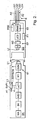
In
In
Der Sensorkopf SK besteht im Wesentlichen aus einem Messaufnehmer MA, der zur Erfassung einer physikalischen Messgröße z. B. pH-Wert, Temperatur etc. dient. Dem Messaufnehmer MA ist eine analoge Signalverarbeitungseinheit SV nachgeschaltet, in dem das analoge Messsignal vorverarbeitet z. B. gefiltert oder verstärkt wird. Über einem Analog/Digital-Wandler A/D 1 wird das Messsignal einem Mikrocontroller µC1 zugeführt, in dem eine weitere Verarbeitung des Messsignals stattfindet. Über eine Kommunikationsschnittstelle S1 kann der Mikrocontroller µC1 Daten senden und empfangen. Die Kommunikationsschnittstelle S1 besteht aus einem Wandler W1 und einer Spannungsversorgungseinheit SVSK und einer Spule L1.The sensor head SK consists essentially of a sensor MA, which is used to detect a physical quantity z. As pH, temperature, etc. is used. The sensor MA is followed by an analog signal processing unit SV, in which the analog measurement signal preprocessed z. B. filtered or amplified. Via an analog / digital converter A /
Passend zum Sensorkopf SK ist ein Sensorkopfgegenstück SG ausgebildet. Beide sind über eine nicht näher dargestellte Bajonettverbindung miteinander einfach lösbar zu verbinden.Matching the sensor head SK, a sensor head counterpart SG is formed. Both are connected to one another via a bayonet connection, not shown, easily detachable.
Das Sensorkopfgegenstück SG weist eine zur Kommunikationsschnittstelle S1 entsprechende Gegenstelle, die Kommunikationsschnittstelle S2, auf. Diese besteht aus einer Spule L2 einem Verstärker V und einem Wandler W2. Der Wandler W2 ist mit einem Mikrocontroller µC2 verbunden. Die Kommunikation mit dem Leitsystem L erfolgt kabelgebunden über eine Kommunikationsschnittstelle S3, die z. B. aus einem RS-485 Baustein besteht. Das Kabel K weist 4 Leitungen LG1, LG2, LG3, LG4, die von einer Abschirmung AS umgeben sind. Zwei Leitungen sind für die Kommunikation und zwei Leitungen für die Energieübertragung zum Sensorkopfgegenstück SG vorgesehen.The sensor head counterpart SG has a counterpart S1, which corresponds to the communication interface S1, the communication interface S2. This consists of a coil L2 an amplifier V and a converter W2. The converter W2 is connected to a microcontroller μC2. The communication with the control system L is wired via a communication interface S3, the z. B. consists of a RS-485 module. The cable K has 4 lines LG1, LG2, LG3, LG4, which are surrounded by a shield AS. Two wires are for communication and two wires for power transmission to Sensor head counterpart SG provided.
Zur Energieversorgung des Sensorkopfgegenstücks SG dient eine Spannungsversorgungseinheit SVE, die über die Leitungen LG1 und LG2 vom Leitsystem L aus versorgt wird.For the power supply of the sensor head counterpart SG is a power supply unit SVE, which is supplied via the lines LG1 and LG2 from the control system L from.
Der bisher beschriebene Aufbau entspricht dem bekannten Memosens-Sensor.The structure described so far corresponds to the known Memosens sensor.
Die Datenübertragung zwischen den beiden Kommunikationsschnittstellen S1 und S2 erfolgt über eine induktive Kopplung. Gleichzeitig wird über diese Verbindung auch Energie kabellos zum Sensorkopf SK übertragen. Diese Energie wird in der Spannungsversorgungseinheit SVSK gewandelt und in eine entsprechende Versorgungsspannung für die einzelnen Bauelemente umgewandelt.The data transmission between the two communication interfaces S1 and S2 takes place via an inductive coupling. At the same time, energy is transmitted wirelessly to the sensor head SK via this connection. This energy is converted in the power supply unit SVSK and converted into a corresponding supply voltage for the individual components.
Zwischen dem Leitsystem L und dem Sensor (Sensorkopfgegenstück bzw. Sensorkopf) werden verschiedene Messdaten, Parametrierdaten und sensorspezifische Daten übertragen z.B. Sensorkennung mit Seriennummer, Produktionsdatum, Hardware- und Software-Version, Messwerte mit Hauptmesswertund Nebenmesswert (i.d.R Temperatur), Kalibrierdaten mit Offset/Steigung, Datum/Uhrzeit, Kalibrationsmethode, Sensorzustand mit Verwendungsdauer unter Extrembedingungen, Kalibrierzyklen, Hilfsparameter zur Zustandsbewertung,Between the control system L and the sensor (sensor head counterpart or sensor head), various measurement data, parameterization data and sensor-specific data are transmitted, e.g. Sensor identification with serial number, production date, hardware and software version, measured values with main measurement and secondary measurement (i.d.R temperature), calibration data with offset / slope, date / time, calibration method, sensor state with duration of use under extreme conditions, calibration cycles, auxiliary parameters for condition evaluation,
Informationen zur Messstelle wie TAG-Nummer, Informationen zum Sensorelement am Sensorkopf wie Meßumfang, Erstinbetriebnahme, Charge.Information about the measuring point, such as TAG number, information on the sensor element on the sensor head, such as measuring range, initial startup, batch.
Bei dem beschriebenen Ausführungsbeispiel sind Sensorkopf SK und Sensorkopfgegenstück SG vollkommen galvanisch getrennt. Diese galvanische Trennung ist insbesondere bei der pH-Messung von großem Vorteil, aber für die vorliegende Erfindung nicht unbedingt erforderlich.In the described embodiment, sensor head SK and sensor head counterpart SG are completely galvanically separated. This galvanic separation is particularly advantageous in the pH measurement, but not necessarily required for the present invention.
Zum Kalibrieren wird der Sensorkopf SK vom Sensorkopfgegenstück SG abgeschraubt und an einem von der Messstelle M1 entfernten Labor transportiert, wo die eigentliche Kalibrierung stattfindet. Dies kann automatisiert erfolgen und die Kalibrierwerte zu jedem Sensorkopf werden eineindeutig zuordenbar in einer Datenbank abgespeichert. Diese Datenbank kann z. B. auch an das lokale Netzwerk angeschlossen sein. Anschließend muss der Sensorkopf an der Messstelle wieder eingesetzt werden, von der er entnommen wurde. Dem Anwender steht beim Austausch der Sensorköpfe eine Box B mit mehreren Sensorköpfen zur Verfügung. Eine solche Box B ist in
Erfindungsgemäß weist der Sensorkopf SK eine Antenne A1 und eine angeschlossenen Funkeinheit F1 auf. Die Funkeinheit F1 kann entweder mit dem Mikrocontroller µCl über die Verbindungsleitung VL verbunden sein oder in einer alternativen Ausgestaltung keine Verbindung zum Mikrocontroller µC1 aufweisen. Die Funkeinheit F1 entspricht einem Transponder, wie sie vielfach in der RFID-Technologie eingesetzt werden. Die Funkeinheit F1 ist dafür ausgelegt ohne fremde Energieversorgung nur mit Hilfe der Funkenergie zu arbeiten.According to the invention, the sensor head SK has an antenna A1 and a connected radio unit F1. The radio unit F1 can either be connected to the microcontroller μC1 via the connection line VL or in one alternative embodiment have no connection to the microcontroller μC1. The radio unit F1 corresponds to a transponder, as they are widely used in RFID technology. The radio unit F1 is designed to work without external power supply only with the help of the radio energy.
Zusätzlich ist die Funkeinheit F1 noch mit der Spannungsversorgungseinheit SVSK verbunden. Dadurch können Daten aus einem in der Funkeinheit F1 vorgesehenen Speicher (EEPROM-Speicher mit 512 Byte Speicherplatz) auch ausgelesen werden, wenn keine Funkenergie zur Verfügung stehen sollte.In addition, the radio unit F1 is still connected to the power supply unit SVSK. As a result, data from a memory provided in the radio unit F1 (EEPROM memory with 512 bytes of memory) can also be read if no radio energy should be available.
Weiterhin ist im Sensorkopfgegenstück SG eine Funkeinheit F2 vorgesehen, die mit dem Mikrocontroller µC2 verbunden ist. Die Antenne A2 der Funkeinheit F2 ist im Kabel K außerhalb der Abschirmung AS vorgesehen.Furthermore, a radio unit F2 is provided in the sensor head counterpart SG, which is connected to the microcontroller μC2. The antenna A2 of the radio unit F2 is provided in the cable K outside the shield AS.
Nachfolgend ist die Funktionsweise des Sensors für die verschiedenen alternativen Ausgestaltungen näher erläutert.The operation of the sensor for the various alternative embodiments is explained in more detail below.
Der Sensorkopf SK ist nicht mit dem Sensorkopfgegenstück verbunden.The sensor head SK is not connected to the sensor head counterpart.
An der Messstelle M1 kann der Anwender, bevor er den Sensorkopf SK aufsetzen will, mit Hilfe eines tragbaren Prüfgeräts PG Daten aus dem noch nicht zusammengesetzten Sensor T1 ermitteln.At the measuring point M1, the user, before he wants to put on the sensor head SK, using a portable tester PG data from the not yet assembled sensor T1 determine.
Hierzu fragt das tragbare Prüfgerät PG, die Kennung des Sensorkopfs SK, die im Speicher EEPROM der Funkeinheit F1 gespeichert ist ab. Die Energieversorgung der Funkeinheit erfolgt bei der Abfrage über diese Funkstrecke (erste Funkstrecke EF1). Die Kennung wird anschließend an das Leitsystem L über eine zweite längere Funkstrecke EF2 übertragen. Anhand der Kennung ermittelt das Leitsystem L die Messstelle für die dieser Sensorkopf SK vorgesehen ist. Anschließend werden messstellenspezifische Daten an die Prüfeinheit PG übertragen und an dieser dargestellt. Diese Daten helfen dem Anwender, den richtigen Sensorkopf SK an der richtigen Messstelle, hier die Messstelle M1, einzusetzen.For this purpose, the portable test device PG, the identifier of the sensor head SK, which is stored in the memory EEPROM of the radio unit F1 asks. The power supply of the radio unit takes place when queried via this radio link (first radio link EF1). The identifier is then transmitted to the control system L via a second longer radio link EF2. Based on the identifier, the control system L determines the measuring point for which this sensor head SK is provided. Subsequently, measuring point-specific data are transmitted to the test unit PG and displayed at this. These data help the user to insert the correct sensor head SK at the right measuring point, here the measuring point M1.
Hierzu wird wieder die Kennung des Sensorkopfs SK vom Prüfgerät PG wie oben beschrieben ausgelesen. Anhand der Kennung ermittelt das Leitsystem L die entsprechende Messstelle M1 für die der Sensorkopf SK vorgesehen ist. Nun fragt das Leitsystem L die entsprechende Messstelle M direkt über die Kabelverbindung ab, und ermittelt so die Kennung des tatsächlich an dieser Messstelle M1 eingesetzten Sensorkopfs SK. Wenn der Sensorkopf SK an der richtigen Messstelle eingesetzt wurde, müssen die Kennung die vom Prüfgerät PG ans Leitsystem L übertragen wurde und die vom Leitsystem L ermittelte Kennung übereinstimmen. Stimmen beide Kennungen überein so wird eine entsprechende Klarmeldung ("Messstelle o. k.") vom Leitsystem L an das Prüfgerät PG gesendet.For this purpose, the identifier of the sensor head SK is again read by the tester PG as described above. Based on the identifier, the control system L determines the corresponding measuring point M1 for which the sensor head SK is provided. Now the control system L queries the corresponding measuring point M directly via the cable connection, and thus determines the identifier of the sensor head SK actually used at this measuring point M1. If the sensor head SK has been inserted at the correct measuring point, the identifier transferred from the tester PG to the control system L and the identification determined by the control system L must match. If both identifiers match, then a corresponding clear message ("measuring point ok") of the Control system L sent to the tester PG.
Diese Information wird dem Anwender an der Messstelle M1 direkt angezeigt. Damit sieht der Anwender unmittelbar, dass der richtige Sensorkopf an dieser Messstelle eingesetzt wurde.This information is displayed directly to the user at measuring point M1. The user immediately sees that the right sensor head has been used at this measuring point.
Falls ein falscher Sensorkopf eingesetzt wurde, stimmen die beiden Kennungen nicht überein, und das Leitsystem L sendet in diesem Fall eine entsprechende Fehlermeldung ("falscher Sensorkopf") an das Prüfgerät PG.If a wrong sensor head has been used, the two identifiers do not match, and in this case the control system L sends a corresponding error message ("incorrect sensor head") to the test device PG.
Damit wird ein fehlerhaftes Einsetzen eines Sensorkopfs an einer Messstelle einfach und zuverlässig vermieden. Der Anwender sieht somit unmittelbar nach dem Einbau, ob er den richtigen Sensorkopf an der vorgesehenen Messstelle eingesetzt hat.Thus, a faulty insertion of a sensor head at a measuring point is easily and reliably avoided. The user thus sees immediately after installation whether he has used the correct sensor head at the intended measuring point.
Für den Fall, dass der Sensor T1 in einem metallischen Behälter angeordnet ist, ragt nach dem Einbau nur noch das Ende des Sensorkopfgegenstücks aus dem Behälter heraus. Eine Kommunikation zwischen Funkeinheit F1 und dem Prüfgerät PG, das sich außerhalb des Behälters befindet, ist nun nicht mehr möglich.In the event that the sensor T1 is arranged in a metallic container, after installation only the end of the sensor head counterpart projects out of the container. A communication between radio F1 and the tester PG, which is located outside the container, is no longer possible.
In diesen Fall kommt die Funkeinheit F2 zum Einsatz. Die Kommunikation erfolgt nun zwischen Prüfgerät PG und Funkeinheit F2. Die Funkeinheit F2 fordert die Kennung des Sensorkopfs über den Mikrocontroller µC2 vom Sensorkopf SK an. Das Auslesen der Kennung aus dem EEPROM-Speicher der Funkeinheit F1 ist deshalb möglich, da die Funkeinheit F1 direkt mit dem Mikrocontroller µC1 kommunizieren kann, der über die Spannungsversorgungseinheit SVSK versorgt wird. Da der Sensorkopf SK in einen metallischen Behälter ragt, kann aufgrund der Abschirmung keine Funkenergie an die Funkeinheit F1 übertragen werden. In diesem Fall kann der Sensorkopf auch im eingebauten Zustand vom Anwender identifiziert werdenIn this case, the radio unit F2 is used. Communication now takes place between test device PG and radio unit F2. The radio unit F2 requests the identification of the sensor head via the microcontroller μC2 from the sensor head SK. The reading of the identifier from the EEPROM memory of the radio unit F1 is therefore possible because the radio unit F1 can communicate directly with the microcontroller μC1, which is supplied via the power supply unit SVSK. Since the sensor head SK projects into a metallic container, due to the shielding, no radio energy can be transmitted to the radio unit F1. In this case, the sensor head can also be identified by the user when installed
Sind mehrere Messstellen M1, M2, M3 relativ nahe beieinander angeordnet, so tritt das Problem auf, dass das Prüfgerät PG mit Funkeinheiten von verschiedenen Messstellen in Kontakt treten kann. Der Anwender ist in diesem Fall nicht ganz sicher mit welcher Messstelle das Prüfgerät PG tatsächlich kommuniziert. Die Information "Messstelle o. k." könnte prinzipiell auch von einer benachbarten Messstelle stammen und nicht von der Messstelle, die der Anwender eigentlich prüfen will.If several measuring points M1, M2, M3 are arranged relatively close to one another, the problem arises that the test device PG can come into contact with radio units from different measuring points. In this case, the user is not quite sure with which measuring point the test device PG actually communicates. The information "Messstelle o. K." could in principle also come from an adjacent measuring point and not from the measuring point, which the user actually wants to check.
Aus diesem Grund weist das Prüfgerät erfindungsgemäß eine zangenförmige Antenne APG auf, die um die Antenne A2 gelegt werden muss, um eine Kommunikation mit genau diesem Sensor zu ermöglichen.For this reason, the tester according to the invention a pincer-shaped antenna APG, which must be placed around the antenna A2 to allow communication with this exact sensor.
Damit kann der Anwender sicher sein, dass die Prüfung der richtigen Messstelle mit dem unmittelbar vor ihm befindlichen Sensor T1 erfolgt. Verwechslungen sind dadurch absolut ausgeschlossen.This allows the user to be sure that the test of the correct measuring point is carried out with the sensor T1 located directly in front of it. Mistakes are therefore completely excluded.
Die Erfindung eignet sich nicht nur für den Austausch von Sensorköpfen sondern auch für den erstmaligen Einsatz. In diesem Fall muss nur sichergestellt werden, dass im Leitsystem L die Messstelle mit der Kennung des entsprechenden Sensorkopf bereits gespeichert sind.The invention is suitable not only for the replacement of sensor heads but also for the first time use. In this case, it only has to be ensured that the measuring point with the identifier of the corresponding sensor head is already stored in the control system L.
Das Prüfgerät PG ist prinzipiell für zwei unterschiedliche Funkkommunikationsmethoden ausgelegt. Zum einen die Kommunikation mit der Funkeinheit F1 entsprechend der RFID-Technik und zum anderen mit der Funkeinheit F2 oder dem Leitsystem L zum Beispiel nach dem ZigBee-Standard.The tester PG is designed in principle for two different radio communication methods. On the one hand, the communication with the radio unit F1 according to the RFID technology and on the other with the radio unit F2 or the control system L, for example, according to the ZigBee standard.
Nachfolgend besteht die Verbindung über die Verbindungsleitung VL zwischen Funkeinheit F1 und Mikrocontroller µC1 nicht. In der Funkeinheit F1 und im Mikrocontroller µC1 sind eine Unique ID-Kennung gespeichert. Bei der Produktion des Sensorkopfs SK muss gewährleistet werden, dass diese beiden Kennungen gleich sind.Subsequently, the connection via the connecting line VL between the radio unit F1 and microcontroller μC1 does not exist. In the radio unit F1 and in the microcontroller μC1, a unique ID identifier is stored. When producing the sensor head SK, it must be ensured that these two identifiers are the same.
Über diese Unique ID-Kennung kann die Seriennummer des Sensorkopfs SK ermittelt werden und damit Daten zu dem betreffenden Sensorkopf aus einer Datenbank abgerufen werden. Die Datenbank kann z. B. direkt im Prüfgerät PG gespeichert sein. Sollte dies nicht der Fall sein, so kann alternativ die Datenbankabfrage auch über die Funkstrecke ZFS erfolgen.This unique ID identifier can be used to determine the serial number of the sensor head SK and thus retrieve data for the relevant sensor head from a database. The database can z. B. stored directly in the tester PG. If this is not the case, alternatively the database query can also be made via the radio link ZFS.
In jedem Fall können Sensordaten z. B. der Messwert auch direkt über die Funkeinheit F1 bzw. F2 aus dem Sensor ausgelesen werden.In any case, sensor data z. B. the measured value can also be read directly from the sensor via the radio unit F1 or F2.
Für den Anwender gibt es eine zusätzliche Sicherheit, wenn er vor Ort den Messwert mit Hilfe des Prüfgeräts PG abfragen kann und anschließend in der Warte überprüfen kann. Stimmen beide überein so gibt dies zusätzliche Sicherheit.For the user, there is additional security if he can query the measured value locally with the aid of the test device PG and then check in the control room. If both agree, this gives additional security.
Nachfolgend sind noch einmal alle Anwendungsfälle der Erfindung systematisch aufgeführt. Die Erfindung betrifft generell die Kommunikation mit einem Sensor über die erste Funkstrecke EFS. Hierbei werden zwei Methoden beachtet: 1. Kommunikation mit der Funkeinheit F1 und Versorgung der Funkeinheit F1 aus dem Funkfeld; 2. Kommunikation über einen Nahbereichsfunk (zum Beispiel Zigbee, Nanonet o.a.) mit der Funkeinheit F2 im Sensorkopfgegenstück SG.In the following, once again all applications of the invention are listed systematically. The invention generally relates to communication with a sensor via the first radio link EFS. Two methods are observed here: 1. Communication with the radio unit F1 and supply of the radio unit F1 from the radio field; 2. Communication via a short-range radio (for example, Zigbee, Nanonet, etc.) with the radio unit F2 in the sensor head counterpart SG.
Für die Kommunikation nach der ersten Methode gibt es unterschiedliche Anwendungsfälle: 1. Die Funkeinheit F1 hat keine Verbindung zum Mikrocontroller µC1 und zur Spannungsversorgungseinheit SVSK. Spezielle Sensordaten sind im EEPROM gespeichert und nur über den Mikrocontroller µC1 zugreifbar. Hierbei sind folgende Spezialfälle denkbar: 1.1 Der Sensor ist in der Box B und nicht mit dem Sensorkopfgegenstück SG verbunden. Es erfolgt die Abfrage einer Kennung des Sensors (Unique ID) mit Versorgung durch das Funkfeld aus dem Sensorkopf SK. Die Unique ID wird in eine Messstellennummer oder Sensornummer durch eine im Prüfgerät PG vorgesehene Datenbank umgewandelt. Mit diesen Informationen kann eine Anfrage der Korrektheit der Messstelle über die zweite Funkstrecke ZFS an das Leitsystem L erfolgen. Alternativ kann hierzu eine direkte Anfrage unter Verwendung der Unique ID über die zweite Funkstrecke ZFS beim Leitsystem L auf Korrektheit der Verwendung erfolgen. Die Anzeige der Antwort erfolgt über die zweite Funkstrecke ZFS auf dem Prüfgerät PG.
- 1.2 Nun wird der Fall betrachtet, dass der Sensor am Kabel K über das Sensorkopfgegenstück SG angeschlossen ist und keine Abschirmung durch die Armatur erfolgt. Hier erfolgt wieder eine Abfrage der Unique ID mit Versorgung durch das Funkfeld aus dem Sensorkopf SK. Die Unique ID wird in die Messstellennummer durch eine Datenbank im Prüfgerät PG umgeschlüsselt. Anschließend erfolgt eine Anfrage nach Sensordaten auch Messwerte über die zweite Funkstrecke ZVS an das Leitsystem L. Alternativ kann eine direkte Anfrage unter Verwendung der Unique ID über die zweite Funkstrecke ZVS beim Leitsystem L nach Sensordaten (auch Messwerte) erfolgen. Die Anzeige der Antwort erfolgt über die zweite Funkstrecke ZFS auf dem Prüfgerät PG.
- 1.3 Eine dritte Alternative ergibt sich, wenn der Sensor am Kabel über das Steckergegenstück SG angeschlossen ist, aber eine Abschirmung der ersten Funkstrecke EFS durch die Armatur erfolgt. Hier ist eine Abfrage der Sensordaten über die erste Funkstrecke via Antenne A2 und Funkeinheit F2 möglich. Die Abfrage wird über den Mikrocontroller µC2 in den von der Kommunikationsschnittstelle S3/LG3/LG4 kommenden Datenstrom über den Wandler W2 und den Verstärker V sowie die Spule L2 an dem Sensorkopf SK eingeschleust. Die Antwort vom Sensorkopf SK wird durch den Mikrocontroller µC2 ausgeschleust und die Antwort über die Funkeinheit F2 und die
Antenne 2 an das Prüfgerät PG abgesetzt. Anschließend erfolgt die Anzeige der Antwort über die erste Funkstrecke EFS von der Funkeinheit F2 auf dem Prüfgerät PG.
- 1.2 Consider now the case that the sensor is connected to the cable K via the sensor head counterpart SG and no shielding by the fitting takes place. Here again a query of the Unique ID with supply by the radio field from the sensor head SK takes place. The unique ID is converted into the tag number by a database in the PG tester. Subsequently, a request for sensor data and measured values via the second radio link ZVS to the control system L. Alternatively, a direct request using the Unique ID via the second radio link ZVS in the control system L according to sensor data (also measured values). The response is displayed via the second radio link ZFS on the test device PG.
- 1.3 A third alternative arises when the sensor is connected to the cable via the connector counterpart SG, but a shielding of the first radio link EFS is performed by the valve. Here, a query of the sensor data on the first radio link via antenna A2 and radio unit F2 is possible. The interrogation is introduced via the microcontroller μC2 into the data stream coming from the communication interface S3 / LG3 / LG4 via the converter W2 and the amplifier V as well as the coil L2 at the sensor head SK. The response from the sensor head SK is discharged by the microcontroller μC2 and the response via the radio unit F2 and the
antenna 2 to the tester PG deposited. Subsequently, the display of the answer via the first radio link EFS of the radio unit F2 on the test device PG.
Nun wird der zweite Anwendungsfall betrachtet.
- 2. Hier hat die Funkeinheit F1 eine elektrische Verbindung über die Verbindungsleitung VL zum Mikrocontroller µC1 und auch eine Verbindung zum Datenspeicher EEPROM und der Spannungsversorgungseinheit SVSK. Auch hier sind wieder folgende spezielle Anwendungsfälle denkbar:
- 2.1 Der Sensor befindet sich in der Box B und ist nicht am Kabel über das Sensorkopfgegenstück SG angeschlossen. Die Abfrage der Sensordaten erfolgen direkt aus dem EEPROM des Sensorkopfs SK, welches Teil der Funkeinheit F1 ist. Die Versorgung erfolgt durch das Funkfeld. Anschließend erfolgt eine Anzeige der Antwort über die erste Funkstrecke EFS auf dem Prüfgerät PG.
- 2.2 In einem weiteren Spezialfall ist der Sensor an Kabel K über das Sensorkopfgegenstück SG angeschlossen, wobei keine Abschirmung durch die Armatur erfolgt. Die Abfrage der Sensordaten und der Messwerte erfolgt direkt aus dem EEPROM und dem Mikrocontroller µC1 des Sensorkopfs SK, welcher Teil der Funkeinheit F1 ist. Auch hier erfolgt wieder die Versorgung durch das Funkfeld. Die Anzeige der Antwort erfolgt über die erste Funkstrecke EFS auf dem Prüfgerät PG.
- 2. Here, the radio unit F1 has an electrical connection via the connection line VL to the microcontroller μC1 and also a connection to the data memory EEPROM and the power supply unit SVSK. Again, the following special applications are conceivable:
- 2.1 The sensor is in Box B and is not on the cable over the Sensor head counterpart SG connected. The query of the sensor data is done directly from the EEPROM of the sensor head SK, which is part of the radio unit F1. The supply takes place through the radio field. Subsequently, the response via the first radio link EFS is displayed on the test device PG.
- 2.2 In another special case, the sensor is connected to cable K via the sensor head counterpart SG, whereby no shielding takes place through the fitting. The interrogation of the sensor data and the measured values takes place directly from the EEPROM and the microcontroller μC1 of the sensor head SK, which is part of the radio unit F1. Again, the supply is made by the radio field. The response is displayed via the first radio link EFS on the test device PG.
Der Spezialfall 2.3 entspricht dem Fall 1.3.The special case 2.3 corresponds to case 1.3.
Claims (5)
- Sensor for a measuring point consisting of a sensor head (SK) and a sensor head counter-piece (SG), which can be detachably connected to one another, wherein the sensor head (SK) has a measuring sensor (MA) designed to record measured values, a first microcontroller (µC1) designed to process the measured values, a voltage supply unit (SVSK) designed to supply energy to the sensor head (SK), and a communication interface (S1) designed to exchange data with the sensor head counter-piece (SG), wherein the sensor head counter-piece is connected to a control system to which the processed measured values are forwarded, characterized in that
the first microcontroller (µC1) is connected to a radio unit (F1), which is connected to the voltage supply unit (SVSK) of the sensor head and which has an additional separate voltage supply unit (SVF1) and an accumulator, wherein the additional separate voltage supply unit (SVF1) is powered via radio energy and in this way enables the exchange of data via radio technology even if the voltage supply unit (SVSK) does not supply any energy for the sensor head (SK). - Sensor as claimed in Claim 1, characterized in that data exchange between the sensor head (SK) and the sensor head counter-piece (SG) is wireless and in that the energy supply of the voltage supply unit (SVSK) of the sensor head (SK) is also via wireless technology.
- Sensor for a measuring point as claimed in one of the previous claims, wherein the sensor head counter-piece (SG) has a communication interface (S2) designed for data communication and/or energy transmission with the sensor head (SK), a microcontroller (µC2) and a communication interface (S2) for the transmission of data to the control system (L), characterized in that the microcontroller (µC2) is connected to a radio unit (F2).
- Procedure for checking a sensor for a measuring point which has a sensor head (SK) and a sensor head counter-piece (SG), which can be detachably interconnected via a plug connection, wherein the sensor head counter-piece (SG) is connected to a control system (L) via a cable connection, said procedure comprising the following steps:1. An identification code of the sensor head (SK) is read into a portable testing device (PG) via a first radio path (EFS);2. The identification code is transmitted from the testing device (PG) to the control system via a second radio path (ZFS);3. Data specific to the measuring point are transmitted from the control system (L) to the testing device (PG);4. The data specific to the measuring point are visualized on the testing device (PG).
- Procedure as claimed in Claim 4, wherein the sensor head (SK) and the sensor head counter-piece (SG) are connected, said procedure comprising the following steps:5. The control system (L) polls the measuring point (M1) assigned to the identification code of the sensor head (SK);6. If the two identification codes match, a clear message is sent by the control system (L) to the testing device (PG) as a data unit specific to the measuring point;7. If the two identification codes do not match, an error message to this effect is transmitted as information specific to the measuring point.
Priority Applications (1)
| Application Number | Priority Date | Filing Date | Title |
|---|---|---|---|
| EP16164108.9A EP3091340A1 (en) | 2006-04-26 | 2007-04-13 | Sensor for a measuring point and method for inspecting a sensor for a measuring point |
Applications Claiming Priority (4)
| Application Number | Priority Date | Filing Date | Title |
|---|---|---|---|
| DE102006020016 | 2006-04-26 | ||
| DE200610020341 DE102006020341A1 (en) | 2006-04-28 | 2006-04-28 | Point measuring sensor, has sensor head and sensor head counterpiece, which are detachably connected to each other, and sensor head counterpiece connected with control system, to which processed measuring value is transmitted |
| DE102006028826 | 2006-06-21 | ||
| PCT/EP2007/053609 WO2007125020A1 (en) | 2006-04-26 | 2007-04-13 | Sensor for a measuring point and method for inspecting a sensor for a measuring point |
Related Child Applications (2)
| Application Number | Title | Priority Date | Filing Date |
|---|---|---|---|
| EP16164108.9A Division EP3091340A1 (en) | 2006-04-26 | 2007-04-13 | Sensor for a measuring point and method for inspecting a sensor for a measuring point |
| EP16164108.9A Division-Into EP3091340A1 (en) | 2006-04-26 | 2007-04-13 | Sensor for a measuring point and method for inspecting a sensor for a measuring point |
Publications (2)
| Publication Number | Publication Date |
|---|---|
| EP2010867A1 EP2010867A1 (en) | 2009-01-07 |
| EP2010867B1 true EP2010867B1 (en) | 2017-05-31 |
Family
ID=38512188
Family Applications (2)
| Application Number | Title | Priority Date | Filing Date |
|---|---|---|---|
| EP07728076.6A Active EP2010867B1 (en) | 2006-04-26 | 2007-04-13 | Sensor for a measuring point and method for inspecting a sensor for a measuring point |
| EP16164108.9A Withdrawn EP3091340A1 (en) | 2006-04-26 | 2007-04-13 | Sensor for a measuring point and method for inspecting a sensor for a measuring point |
Family Applications After (1)
| Application Number | Title | Priority Date | Filing Date |
|---|---|---|---|
| EP16164108.9A Withdrawn EP3091340A1 (en) | 2006-04-26 | 2007-04-13 | Sensor for a measuring point and method for inspecting a sensor for a measuring point |
Country Status (4)
| Country | Link |
|---|---|
| US (2) | US8285518B2 (en) |
| EP (2) | EP2010867B1 (en) |
| CN (1) | CN101432595B (en) |
| WO (1) | WO2007125020A1 (en) |
Families Citing this family (9)
| Publication number | Priority date | Publication date | Assignee | Title |
|---|---|---|---|---|
| US20170090002A9 (en) * | 2006-04-26 | 2017-03-30 | Endress + Hauser Conducta Gesellschaft Fur Mess - Und Regeltechnik Mbh + Co. Kg | Sensor for a Measuring Point and Method for Testing a Sensor for a Measuring Point |
| DE102007053223A1 (en) * | 2007-11-06 | 2009-05-07 | Endress + Hauser Conducta Gesellschaft für Mess- und Regeltechnik mbH + Co. KG | Method for operating a measuring point, measuring point and sensor unit for such a measuring point |
| DE102012109680A1 (en) | 2012-10-11 | 2014-05-15 | Endress + Hauser Gmbh + Co. Kg | Device and system for determining, optimizing or monitoring at least one process variable |
| DE102013111714A1 (en) * | 2013-10-24 | 2015-04-30 | Endress + Hauser Conducta Gesellschaft für Mess- und Regeltechnik mbH + Co. KG | Method for setting the function of a measuring point and measuring point |
| TWI651621B (en) * | 2013-12-18 | 2019-02-21 | 財團法人國家實驗研究院 | Sensing system with re-modularized sensing device and initialization method using the same |
| DE102014015129A1 (en) * | 2014-10-14 | 2016-04-14 | Wabco Gmbh | Method for identifying a sensor device for speed measurement, sensor device for speed measurement and vehicle with at least one sensor device for speed measurement |
| DE102017128741A1 (en) * | 2017-12-04 | 2019-06-06 | Endress+Hauser Conducta Gmbh+Co. Kg | Sensor connection element for a sensor and sensor system |
| EP3841357B1 (en) * | 2018-10-15 | 2022-11-23 | Refco Manufacturing Ltd. | Intelligent measuring apparatus |
| DE102018132384A1 (en) * | 2018-12-17 | 2020-06-18 | Endress+Hauser Conducta Gmbh+Co. Kg | Hardware-software communication system for sensor signal monitoring in process automation technology |
Citations (1)
| Publication number | Priority date | Publication date | Assignee | Title |
|---|---|---|---|---|
| DE10313639A1 (en) * | 2003-03-26 | 2004-10-07 | Endress + Hauser Conducta Gesellschaft für Mess- und Regeltechnik mbH + Co. KG | Electrochemical gas sensor |
Family Cites Families (13)
| Publication number | Priority date | Publication date | Assignee | Title |
|---|---|---|---|---|
| US5597534A (en) * | 1994-07-05 | 1997-01-28 | Texas Instruments Deutschland Gmbh | Apparatus for wireless chemical sensing |
| DE19722744A1 (en) | 1997-05-30 | 1998-12-03 | Draegerwerk Ag | Detection system with interchangeable sensors |
| DE19849293A1 (en) | 1998-10-26 | 2000-04-27 | Ibtl Ing Buero Lang & Partner | Test result recording system for recording readings at several measurement points of object in test facility, e.g. for chassis dynamometer; outputs signal when measurement point of tested object is in predetermined state |
| US6720866B1 (en) * | 1999-03-30 | 2004-04-13 | Microchip Technology Incorporated | Radio frequency identification tag device with sensor input |
| US6182497B1 (en) | 1999-08-20 | 2001-02-06 | Neodym Systems Inc | Gas detection system and method |
| US6294997B1 (en) * | 1999-10-04 | 2001-09-25 | Intermec Ip Corp. | RFID tag having timing and environment modules |
| DE10032864B4 (en) | 2000-07-06 | 2004-03-04 | Abb Research Ltd. | Proximity sensor adapter |
| DE10064812A1 (en) * | 2000-12-22 | 2002-06-27 | Endress & Hauser Gmbh & Co Kg | Device for emitting high frequency signals used in radar systems has a radiating element arranged at an angle to the rear wall of a wave guide |
| DE20107113U1 (en) | 2001-04-25 | 2001-07-05 | Abb Patent Gmbh | Device for supplying energy to field devices |
| DE10241241B4 (en) | 2002-09-06 | 2004-08-05 | Abb Research Ltd. | Process for the measurement of a measurement device |
| DE10305986B4 (en) * | 2003-02-12 | 2022-07-21 | IAD Gesellschaft für Informatik, Automatisierung und Datenverarbeitung mbH | Measuring system with intelligent sensor head for medium or high voltage systems or in mining |
| US7040139B2 (en) | 2003-06-10 | 2006-05-09 | Smiths Detection Inc. | Sensor arrangement |
| DE10344262A1 (en) * | 2003-09-23 | 2005-04-14 | Endress + Hauser Conducta Gesellschaft für Mess- und Regeltechnik mbH + Co. KG | Plug-in module for a liquid or gas sensor |
-
2007
- 2007-04-13 EP EP07728076.6A patent/EP2010867B1/en active Active
- 2007-04-13 EP EP16164108.9A patent/EP3091340A1/en not_active Withdrawn
- 2007-04-13 US US12/226,621 patent/US8285518B2/en active Active
- 2007-04-13 WO PCT/EP2007/053609 patent/WO2007125020A1/en active Application Filing
- 2007-04-13 CN CN2007800151033A patent/CN101432595B/en not_active Expired - Fee Related
-
2012
- 2012-09-13 US US13/613,114 patent/US8606546B2/en active Active
Patent Citations (1)
| Publication number | Priority date | Publication date | Assignee | Title |
|---|---|---|---|---|
| DE10313639A1 (en) * | 2003-03-26 | 2004-10-07 | Endress + Hauser Conducta Gesellschaft für Mess- und Regeltechnik mbH + Co. KG | Electrochemical gas sensor |
Also Published As
| Publication number | Publication date |
|---|---|
| WO2007125020A1 (en) | 2007-11-08 |
| CN101432595B (en) | 2011-05-18 |
| EP3091340A1 (en) | 2016-11-09 |
| US8285518B2 (en) | 2012-10-09 |
| US8606546B2 (en) | 2013-12-10 |
| US20130013258A1 (en) | 2013-01-10 |
| EP2010867A1 (en) | 2009-01-07 |
| CN101432595A (en) | 2009-05-13 |
| US20090299700A1 (en) | 2009-12-03 |
Similar Documents
| Publication | Publication Date | Title |
|---|---|---|
| EP2010867B1 (en) | Sensor for a measuring point and method for inspecting a sensor for a measuring point | |
| DE102006020341A1 (en) | Point measuring sensor, has sensor head and sensor head counterpiece, which are detachably connected to each other, and sensor head counterpiece connected with control system, to which processed measuring value is transmitted | |
| DE102013013299A1 (en) | Method for operating a field device | |
| DE102009045386A1 (en) | Method for operating a fieldbus interface | |
| DE102008007230A1 (en) | Methods and apparatus for configuring process control system inputs and outputs | |
| DE102008038415A1 (en) | Method for monitoring the state of charge or the residual capacity of a battery or a battery in automation technology | |
| DE102007059671A1 (en) | A method of operating a system comprising a field device and an operating system | |
| DE102012105446B4 (en) | Device for determining and / or monitoring a chemical or physical process variable in automation technology | |
| EP2024711B1 (en) | Method for calibrating and/or adjusting a sensor | |
| DE102017105809A1 (en) | measuring arrangement | |
| WO2014095256A1 (en) | Field device and method for reading data from an inactive or defective field device | |
| DE102012107673A1 (en) | Method for replacing field device of automation equipment in modern industrial system, involves linking and/or depositing parameter set with identification mark on web server based on another identification mark | |
| DE102008043336A1 (en) | Modular meter with distributed data and algorithms | |
| DE102009046041A1 (en) | Field device e.g. level indicator, operating arrangement for use in process automation system, has controlling unit and field devices performing cyclic or acyclic data communication, where field devices include extended functionality | |
| EP3125053B1 (en) | Method and peripheral module for the transmission of hart variables and cpu unit for reading the hart variables | |
| EP1800193A1 (en) | Method for operating a modularly constructed automation technology field device | |
| DE102010062657A1 (en) | Method for providing calibration data to temperature sensor in temperature gauge, involves centrally managing calibration data with associated identifiers for primary temperature sensor, transducer and transmitter in database system | |
| DE102012016406A1 (en) | Method for parameterizing a field device and corresponding system for parameterization | |
| WO2012028366A1 (en) | Method for ensuring proper functioning of an automation system | |
| DE102018118872A1 (en) | Method for checking the data transmission of an electronic switching device | |
| DE102008042919A1 (en) | Field devices for process automation device, have field bus interface, and are formed for communication of fieldbus-protocol, where field devices have also field-device-specific device identification that is specific for field-device-type | |
| EP3652595A1 (en) | Method and data conversion unit for monitoring an automation system | |
| DE102007052125A1 (en) | Component e.g. printed circuit board, carrier testing system for use in microelectronics field, has communication interfaces assigned to communication units for displaying and/or processing component-specific data | |
| EP2010898B1 (en) | Transport container for a plurality of potentiometric sensors | |
| DE102010003741A1 (en) | Method for data exchange |
Legal Events
| Date | Code | Title | Description |
|---|---|---|---|
| PUAI | Public reference made under article 153(3) epc to a published international application that has entered the european phase |
Free format text: ORIGINAL CODE: 0009012 |
|
| 17P | Request for examination filed |
Effective date: 20081021 |
|
| AK | Designated contracting states |
Kind code of ref document: A1 Designated state(s): AT BE BG CH CY CZ DE DK EE ES FI FR GB GR HU IE IS IT LI LT LU LV MC MT NL PL PT RO SE SI SK TR |
|
| AX | Request for extension of the european patent |
Extension state: AL BA HR MK RS |
|
| 17Q | First examination report despatched |
Effective date: 20120314 |
|
| DAX | Request for extension of the european patent (deleted) | ||
| RAP1 | Party data changed (applicant data changed or rights of an application transferred) |
Owner name: ENDRESS + HAUSER CONDUCTA GMBH+CO. KG |
|
| REG | Reference to a national code |
Ref country code: DE Ref legal event code: R079 Ref document number: 502007015669 Country of ref document: DE Free format text: PREVIOUS MAIN CLASS: G01D0005480000 Ipc: G01D0021000000 |
|
| RIC1 | Information provided on ipc code assigned before grant |
Ipc: H03K 17/95 20060101ALI20161025BHEP Ipc: G01D 5/48 20060101ALI20161025BHEP Ipc: G01D 21/00 20060101AFI20161025BHEP |
|
| GRAP | Despatch of communication of intention to grant a patent |
Free format text: ORIGINAL CODE: EPIDOSNIGR1 |
|
| INTG | Intention to grant announced |
Effective date: 20161222 |
|
| GRAS | Grant fee paid |
Free format text: ORIGINAL CODE: EPIDOSNIGR3 |
|
| GRAA | (expected) grant |
Free format text: ORIGINAL CODE: 0009210 |
|
| AK | Designated contracting states |
Kind code of ref document: B1 Designated state(s): AT BE BG CH CY CZ DE DK EE ES FI FR GB GR HU IE IS IT LI LT LU LV MC MT NL PL PT RO SE SI SK TR |
|
| REG | Reference to a national code |
Ref country code: CH Ref legal event code: EP Ref country code: GB Ref legal event code: FG4D Free format text: NOT ENGLISH |
|
| REG | Reference to a national code |
Ref country code: AT Ref legal event code: REF Ref document number: 897907 Country of ref document: AT Kind code of ref document: T Effective date: 20170615 |
|
| REG | Reference to a national code |
Ref country code: IE Ref legal event code: FG4D Free format text: LANGUAGE OF EP DOCUMENT: GERMAN |
|
| REG | Reference to a national code |
Ref country code: DE Ref legal event code: R096 Ref document number: 502007015669 Country of ref document: DE |
|
| REG | Reference to a national code |
Ref country code: NL Ref legal event code: MP Effective date: 20170531 |
|
| REG | Reference to a national code |
Ref country code: LT Ref legal event code: MG4D |
|
| PG25 | Lapsed in a contracting state [announced via postgrant information from national office to epo] |
Ref country code: ES Free format text: LAPSE BECAUSE OF FAILURE TO SUBMIT A TRANSLATION OF THE DESCRIPTION OR TO PAY THE FEE WITHIN THE PRESCRIBED TIME-LIMIT Effective date: 20170531 Ref country code: LT Free format text: LAPSE BECAUSE OF FAILURE TO SUBMIT A TRANSLATION OF THE DESCRIPTION OR TO PAY THE FEE WITHIN THE PRESCRIBED TIME-LIMIT Effective date: 20170531 Ref country code: FI Free format text: LAPSE BECAUSE OF FAILURE TO SUBMIT A TRANSLATION OF THE DESCRIPTION OR TO PAY THE FEE WITHIN THE PRESCRIBED TIME-LIMIT Effective date: 20170531 Ref country code: GR Free format text: LAPSE BECAUSE OF FAILURE TO SUBMIT A TRANSLATION OF THE DESCRIPTION OR TO PAY THE FEE WITHIN THE PRESCRIBED TIME-LIMIT Effective date: 20170901 |
|
| PG25 | Lapsed in a contracting state [announced via postgrant information from national office to epo] |
Ref country code: SE Free format text: LAPSE BECAUSE OF FAILURE TO SUBMIT A TRANSLATION OF THE DESCRIPTION OR TO PAY THE FEE WITHIN THE PRESCRIBED TIME-LIMIT Effective date: 20170531 Ref country code: LV Free format text: LAPSE BECAUSE OF FAILURE TO SUBMIT A TRANSLATION OF THE DESCRIPTION OR TO PAY THE FEE WITHIN THE PRESCRIBED TIME-LIMIT Effective date: 20170531 Ref country code: BG Free format text: LAPSE BECAUSE OF FAILURE TO SUBMIT A TRANSLATION OF THE DESCRIPTION OR TO PAY THE FEE WITHIN THE PRESCRIBED TIME-LIMIT Effective date: 20170831 Ref country code: IS Free format text: LAPSE BECAUSE OF FAILURE TO SUBMIT A TRANSLATION OF THE DESCRIPTION OR TO PAY THE FEE WITHIN THE PRESCRIBED TIME-LIMIT Effective date: 20170930 Ref country code: NL Free format text: LAPSE BECAUSE OF FAILURE TO SUBMIT A TRANSLATION OF THE DESCRIPTION OR TO PAY THE FEE WITHIN THE PRESCRIBED TIME-LIMIT Effective date: 20170531 |
|
| PG25 | Lapsed in a contracting state [announced via postgrant information from national office to epo] |
Ref country code: RO Free format text: LAPSE BECAUSE OF FAILURE TO SUBMIT A TRANSLATION OF THE DESCRIPTION OR TO PAY THE FEE WITHIN THE PRESCRIBED TIME-LIMIT Effective date: 20170531 Ref country code: CZ Free format text: LAPSE BECAUSE OF FAILURE TO SUBMIT A TRANSLATION OF THE DESCRIPTION OR TO PAY THE FEE WITHIN THE PRESCRIBED TIME-LIMIT Effective date: 20170531 Ref country code: SK Free format text: LAPSE BECAUSE OF FAILURE TO SUBMIT A TRANSLATION OF THE DESCRIPTION OR TO PAY THE FEE WITHIN THE PRESCRIBED TIME-LIMIT Effective date: 20170531 Ref country code: DK Free format text: LAPSE BECAUSE OF FAILURE TO SUBMIT A TRANSLATION OF THE DESCRIPTION OR TO PAY THE FEE WITHIN THE PRESCRIBED TIME-LIMIT Effective date: 20170531 Ref country code: EE Free format text: LAPSE BECAUSE OF FAILURE TO SUBMIT A TRANSLATION OF THE DESCRIPTION OR TO PAY THE FEE WITHIN THE PRESCRIBED TIME-LIMIT Effective date: 20170531 |
|
| PG25 | Lapsed in a contracting state [announced via postgrant information from national office to epo] |
Ref country code: PL Free format text: LAPSE BECAUSE OF FAILURE TO SUBMIT A TRANSLATION OF THE DESCRIPTION OR TO PAY THE FEE WITHIN THE PRESCRIBED TIME-LIMIT Effective date: 20170531 Ref country code: IT Free format text: LAPSE BECAUSE OF FAILURE TO SUBMIT A TRANSLATION OF THE DESCRIPTION OR TO PAY THE FEE WITHIN THE PRESCRIBED TIME-LIMIT Effective date: 20170531 |
|
| REG | Reference to a national code |
Ref country code: DE Ref legal event code: R097 Ref document number: 502007015669 Country of ref document: DE |
|
| PLBE | No opposition filed within time limit |
Free format text: ORIGINAL CODE: 0009261 |
|
| STAA | Information on the status of an ep patent application or granted ep patent |
Free format text: STATUS: NO OPPOSITION FILED WITHIN TIME LIMIT |
|
| 26N | No opposition filed |
Effective date: 20180301 |
|
| PG25 | Lapsed in a contracting state [announced via postgrant information from national office to epo] |
Ref country code: SI Free format text: LAPSE BECAUSE OF FAILURE TO SUBMIT A TRANSLATION OF THE DESCRIPTION OR TO PAY THE FEE WITHIN THE PRESCRIBED TIME-LIMIT Effective date: 20170531 |
|
| PG25 | Lapsed in a contracting state [announced via postgrant information from national office to epo] |
Ref country code: MT Free format text: LAPSE BECAUSE OF FAILURE TO SUBMIT A TRANSLATION OF THE DESCRIPTION OR TO PAY THE FEE WITHIN THE PRESCRIBED TIME-LIMIT Effective date: 20170531 |
|
| PG25 | Lapsed in a contracting state [announced via postgrant information from national office to epo] |
Ref country code: MC Free format text: LAPSE BECAUSE OF FAILURE TO SUBMIT A TRANSLATION OF THE DESCRIPTION OR TO PAY THE FEE WITHIN THE PRESCRIBED TIME-LIMIT Effective date: 20170531 |
|
| REG | Reference to a national code |
Ref country code: BE Ref legal event code: MM Effective date: 20180430 |
|
| GBPC | Gb: european patent ceased through non-payment of renewal fee |
Effective date: 20180413 |
|
| REG | Reference to a national code |
Ref country code: IE Ref legal event code: MM4A |
|
| PG25 | Lapsed in a contracting state [announced via postgrant information from national office to epo] |
Ref country code: LU Free format text: LAPSE BECAUSE OF NON-PAYMENT OF DUE FEES Effective date: 20180413 |
|
| PG25 | Lapsed in a contracting state [announced via postgrant information from national office to epo] |
Ref country code: GB Free format text: LAPSE BECAUSE OF NON-PAYMENT OF DUE FEES Effective date: 20180413 Ref country code: BE Free format text: LAPSE BECAUSE OF NON-PAYMENT OF DUE FEES Effective date: 20180430 |
|
| PG25 | Lapsed in a contracting state [announced via postgrant information from national office to epo] |
Ref country code: IE Free format text: LAPSE BECAUSE OF NON-PAYMENT OF DUE FEES Effective date: 20180413 Ref country code: FR Free format text: LAPSE BECAUSE OF NON-PAYMENT OF DUE FEES Effective date: 20180430 |
|
| REG | Reference to a national code |
Ref country code: AT Ref legal event code: MM01 Ref document number: 897907 Country of ref document: AT Kind code of ref document: T Effective date: 20180413 |
|
| PG25 | Lapsed in a contracting state [announced via postgrant information from national office to epo] |
Ref country code: AT Free format text: LAPSE BECAUSE OF NON-PAYMENT OF DUE FEES Effective date: 20180413 |
|
| PG25 | Lapsed in a contracting state [announced via postgrant information from national office to epo] |
Ref country code: TR Free format text: LAPSE BECAUSE OF FAILURE TO SUBMIT A TRANSLATION OF THE DESCRIPTION OR TO PAY THE FEE WITHIN THE PRESCRIBED TIME-LIMIT Effective date: 20170531 |
|
| PG25 | Lapsed in a contracting state [announced via postgrant information from national office to epo] |
Ref country code: HU Free format text: LAPSE BECAUSE OF FAILURE TO SUBMIT A TRANSLATION OF THE DESCRIPTION OR TO PAY THE FEE WITHIN THE PRESCRIBED TIME-LIMIT; INVALID AB INITIO Effective date: 20070413 Ref country code: PT Free format text: LAPSE BECAUSE OF FAILURE TO SUBMIT A TRANSLATION OF THE DESCRIPTION OR TO PAY THE FEE WITHIN THE PRESCRIBED TIME-LIMIT Effective date: 20170531 |
|
| PG25 | Lapsed in a contracting state [announced via postgrant information from national office to epo] |
Ref country code: CY Free format text: LAPSE BECAUSE OF FAILURE TO SUBMIT A TRANSLATION OF THE DESCRIPTION OR TO PAY THE FEE WITHIN THE PRESCRIBED TIME-LIMIT Effective date: 20170531 |
|
| PGFP | Annual fee paid to national office [announced via postgrant information from national office to epo] |
Ref country code: CH Payment date: 20220421 Year of fee payment: 16 |
|
| P01 | Opt-out of the competence of the unified patent court (upc) registered |
Effective date: 20230601 |
|
| PGFP | Annual fee paid to national office [announced via postgrant information from national office to epo] |
Ref country code: DE Payment date: 20230420 Year of fee payment: 17 |
|
| REG | Reference to a national code |
Ref country code: CH Ref legal event code: PL |
|
| PG25 | Lapsed in a contracting state [announced via postgrant information from national office to epo] |
Ref country code: LI Free format text: LAPSE BECAUSE OF NON-PAYMENT OF DUE FEES Effective date: 20230430 Ref country code: CH Free format text: LAPSE BECAUSE OF NON-PAYMENT OF DUE FEES Effective date: 20230430 |