EP2010864B1 - Scanning a surface using a coordinate measuring machine - Google Patents
Scanning a surface using a coordinate measuring machine Download PDFInfo
- Publication number
- EP2010864B1 EP2010864B1 EP07724654A EP07724654A EP2010864B1 EP 2010864 B1 EP2010864 B1 EP 2010864B1 EP 07724654 A EP07724654 A EP 07724654A EP 07724654 A EP07724654 A EP 07724654A EP 2010864 B1 EP2010864 B1 EP 2010864B1
- Authority
- EP
- European Patent Office
- Prior art keywords
- scanning
- speed
- freedom
- maximum
- axis
- Prior art date
- Legal status (The legal status is an assumption and is not a legal conclusion. Google has not performed a legal analysis and makes no representation as to the accuracy of the status listed.)
- Active
Links
Images


Classifications
-
- G—PHYSICS
- G01—MEASURING; TESTING
- G01B—MEASURING LENGTH, THICKNESS OR SIMILAR LINEAR DIMENSIONS; MEASURING ANGLES; MEASURING AREAS; MEASURING IRREGULARITIES OF SURFACES OR CONTOURS
- G01B21/00—Measuring arrangements or details thereof, where the measuring technique is not covered by the other groups of this subclass, unspecified or not relevant
- G01B21/02—Measuring arrangements or details thereof, where the measuring technique is not covered by the other groups of this subclass, unspecified or not relevant for measuring length, width, or thickness
- G01B21/04—Measuring arrangements or details thereof, where the measuring technique is not covered by the other groups of this subclass, unspecified or not relevant for measuring length, width, or thickness by measuring coordinates of points
- G01B21/045—Correction of measurements
-
- G—PHYSICS
- G01—MEASURING; TESTING
- G01B—MEASURING LENGTH, THICKNESS OR SIMILAR LINEAR DIMENSIONS; MEASURING ANGLES; MEASURING AREAS; MEASURING IRREGULARITIES OF SURFACES OR CONTOURS
- G01B5/00—Measuring arrangements characterised by the use of mechanical techniques
- G01B5/004—Measuring arrangements characterised by the use of mechanical techniques for measuring coordinates of points
- G01B5/008—Measuring arrangements characterised by the use of mechanical techniques for measuring coordinates of points using coordinate measuring machines
Description
Die Erfindung betrifft ein Verfahren zum Antasten einer Werkstück-Oberfläche mit einem Koordinatenmessgerät und ein Koordinatenmessgerät, welches insbesondere zur Ausführung des Verfahrens ausgestaltet ist. Die Erfindung umfasst ferner eine Ermittlungseinrichtung zur Ermittlung eines Wertes einer Bewegungsgeschwindigkeit des Koordinatenmessgeräts.The invention relates to a method for probing a workpiece surface with a coordinate measuring machine and a coordinate measuring machine, which is designed in particular for carrying out the method. The invention further comprises a determination device for determining a value of a movement speed of the coordinate measuring machine.
Koordinatenmessgeräte werden eingesetzt, um Koordinaten von Oberflächenpunkten eines Werkstücks zu messen. Z. B. weist ein herkömmliches Koordinatenmessgerät eine Werkstückhalterung zum Halten des zu vermessenen Werkstücks in einer Messposition und ein Tastelement zum Antasten der Oberfläche des Werkstücks auf. Im Einzelnen kann das Koordinatenmessgerät mehrere relativ zueinander verlagerbare Komponenten aufweisen, von denen zumindest eine mit der Werkstückhalterung fest verbunden ist und von denen zumindest eine andere das Tastelement trägt, wobei eine Mehrzahl von Antrieben für die Komponenten vorgesehen sind, um das Tastelement relativ zu der Werkstückhalterung zu verlagern (d.h. zu bewegen). Das Tastelement wird beispielsweise von einem Messkopf gehalten. Es kann ferner einen Taster aufweisen. Beim Antasten der Werkstückoberfläche wird das Tastelement mit der Oberfläche in Kontakt gebracht. Bei hergestelltem Kontakt zwischen dem Tastelement und der Oberfläche können die Koordinaten des oder der Punkte gemessen werden, mit denen das Tastelement (das beispielsweise kugelförmig ist) in Kontakt ist.Coordinate measuring machines are used to measure coordinates of surface points of a workpiece. For example, a conventional coordinate measuring machine has a workpiece holder for holding the workpiece to be measured in a measuring position and a probe element for probing the surface of the workpiece. Specifically, the coordinate measuring machine may comprise a plurality of relatively displaceable components, at least one of which is fixedly connected to the workpiece holder and of which at least one other carries the probe element, wherein a plurality of drives for the components are provided to the probe element relative to the workpiece holder to relocate (ie to move). The probe element is held by a measuring head, for example. It may also have a button. When touching the workpiece surface, the probe element is brought into contact with the surface. With contact made between the probe element and the surface, the coordinates of the point (s) with which the probe element (which is, for example, spherical) is in contact can be measured.
Mit Scanning wird ein spezieller Antastmodus bezeichnet, bei welchem Messpunkte fortlaufend aufgenommen werden, um z. B. Linien auf der Oberfläche zu vermessen. Während des Scanning wird das Tastelement auf einem Scanning-Weg bewegt, wobei das Tastelement seinen Kontakt mit der Oberfläche des Werkstücks beibehält.Scanning refers to a special probing mode in which measuring points are recorded continuously in order, for. B. to measure lines on the surface. During scanning, the stylus is moved in a scanning path, with the stylus maintaining its contact with the surface of the workpiece.
Insbesondere kann das Scanning gemäß der vorliegenden Erfindung, wie aus dem Stand der Technik bekannt, mit einem Tastelement ausgeführt, welches zum Beispiel eine Kugel hat, die an der Oberfläche des zu scannenden Gegenstandes entlang geführt wird. Dabei tritt eine Auslenkung (in Bezug auf den Messkopf) der Kugel aus ihrer Null- oder Ruhelage auf. Außerdem tritt aufgrund der Auslenkung eine Rückstellkraft auf, die den mechanischen Kontakt zwischen der Kugel und dem Gegenstand gewährleistet. Aus der momentanen Position des Tastelements und aus der Auslenkung, die insbesondere bezüglich der Ruhelage der Kugel in alle möglichen Richtungen festgestellt werden kann, wird berechnet, an welchem Ort des Koordinatensystems die Kugel den Gegenstand berührt. Die Auslenkung wird über entsprechende Wegaufnehmer am Tastelement erfasst.In particular, the scanning according to the present invention, as known from the prior art, can be carried out with a probe element which, for example, has a ball which is guided along the surface of the object to be scanned. In this case, a deflection occurs (with respect to the measuring head) of the ball from its zero or rest position. In addition, due to the deflection occurs on a restoring force, which ensures the mechanical contact between the ball and the object. From the current position of the probe element and from the deflection, which can be determined in particular with respect to the rest position of the ball in all possible directions, it is calculated at which point of the coordinate system, the ball touches the object. The deflection is detected by corresponding displacement transducer on the probe element.
Auf dem Scanning-Weg wird das Tastelement mit einer Scanning-Geschwindigkeit bewegt. Grundsätzlich kann die Scanning-Geschwindigkeit variieren, d. h. es treten während der Scanning-Bewegung Beschleunigungen und/oder Verzögerungen auf. Die Geschwindigkeitsänderungen können jedoch zu Schwingungen des Gesamtsystems aus Werkstück und Koordinatenmessgerät führen, wodurch Messfehler entstehen.On the scanning path, the probe element is moved at a scanning speed. Basically, the scanning speed can vary, i. H. There are accelerations and / or decelerations during the scanning movement. However, the speed changes can lead to oscillations of the entire system of workpiece and coordinate measuring machine, resulting in measurement errors.
Aufgrund der verschiedenen Antriebe besitzt ein Koordinatenmessgerät häufig unterschiedliche maximal mögliche und/oder maximal zulässige Geschwindigkeiten in Bezug auf die einzelnen Freiheitsgrade der Bewegung des Tastelements. Unter einem Freiheitsgrad der Bewegung wird meist die Bewegungsmöglichkeit in oder parallel zu einer Linearachse verstanden. Z. B. hat ein Koordinatenmessgerät drei voneinander unabhängige lineare Freiheitsgrade der Bewegung, wenn das Tastelement zumindest innerhalb eines bestimmten Messbereichs in beliebige Richtungen bewegt werden kann. Diese drei voneinander unabhängigen Linearachsen werden üblicherweise als die Koordinatenachsen X, Y und Z eines kartesischen Koordinatensystems definiert. Da das Tastelement, bzw. der Punkt des Tastelements, der mit der Werkstückoberfläche in Kontakt kommt, als punktförmig angenommen werden kann und sich die Orientierung des Tastelements bezüglich eines Koordinatensystems, in dem das Werkstück in Ruhe ist, während des Antastens üblicherweise nicht ändert, brauchen weitere Freiheitsgrade der Bewegung, insbesondere rotatorische Freiheitsgrade, nicht betrachtet zu werden. Die Erfindung ist jedoch nicht auf solche Koordinatenmessgeräte bzw. Messanordnungen beschränkt. Insbesondere kann das Koordinatenmessgerät auch über weniger als drei voneinander unabhängige Freiheitsgrade der Bewegung verfügen und/oder kann zumindest einer der Freiheitsgrade ein rotatorischer Freiheitsgrad sein, d. h. das Tastelement kann z. B. durch eine Drehbewegung um eine Drehachse eines Antriebs auf einer Kreisbahn geführt werden.Due to the different drives, a coordinate measuring machine often has different maximum possible and / or maximum permissible speeds with respect to the individual degrees of freedom of the movement of the probe element. One degree of freedom of movement usually means the possibility of movement in or parallel to a linear axis. For example, a coordinate measuring machine has three mutually independent linear degrees of freedom of movement if the probe element can be moved in any direction at least within a certain measuring range. These three independent linear axes are usually defined as the coordinate axes X, Y and Z of a Cartesian coordinate system. Since the probe element, or the point of the probe element, which comes into contact with the workpiece surface can be assumed as punctiform and the orientation of the probe element with respect to a coordinate system in which the workpiece is at rest, during the scanning usually does not change need more degrees of freedom of movement, in particular rotational degrees of freedom, not to be considered. However, the invention is not limited to such coordinate measuring machines or measuring arrangements. In particular, the coordinate measuring machine can also have less than three mutually independent degrees of freedom of the movement and / or can at least one of the degrees of freedom a rotatory Degree of freedom, ie the probe element can, for. B. are guided by a rotational movement about a rotational axis of a drive on a circular path.
Es ist eine Aufgabe der vorliegenden Erfindung, ein Verfahren und ein Koordinatenmessgerät der eingangs genannten Art anzugeben, die es erlauben, beim Scanning die Messdauer möglichst kurz zu halten. Dabei sollen Messfehler verhindert werden und es sollen Messanordnungen berücksichtigt werden, bei denen das Koordinatenmessgerät bzw. das Tastelement bezüglich verschiedener Freiheitsgrade der Bewegung verschiedene maximale Geschwindigkeitsbeträge aufweist. Unter einem maximalen Geschwindigkeitsbetrag eines Freiheitsgrades wird verstanden, dass bei einer Bewegung ausschließlich in der durch den Freiheitsgrad definierten Richtung der zugehörige maximale Geschwindigkeitsbetrag nicht überschritten werden darf oder kann.It is an object of the present invention to provide a method and a coordinate measuring machine of the type mentioned, which allow to keep the measurement duration as short as possible during scanning. In this case, measurement errors are to be prevented and measurement arrangements are to be taken into account, in which the coordinate measuring machine or the probe element has different maximum speed amounts with respect to different degrees of freedom of movement. A maximum speed amount of a degree of freedom is understood to mean that in the case of a movement exclusively in the direction defined by the degree of freedom, the associated maximum speed amount may not or may not be exceeded.
Ein Grundgedanke der vorliegenden Erfindung besteht darin, unter Berücksichtigung des jeweils durch das Tastelement zu durchfahrenden Scanning-Weges zu ermitteln, welchen konstanten, maximal zulässigen Betrag der Scanning-Geschwindigkeit das Tastelement haben darf, wobei die maximalen Geschwindigkeitsbeträge für die einzelnen Freiheitsgrade der Bewegung unterschiedlich sein können. Dem liegt die Erkenntnis zugrunde, dass für dieselbe Form des Scanning-Weges je nach Lage und Orientierung des Scanning-Weges in der Messanordnung verschiedene maximale Beträge der Scanning-Geschwindigkeit resultieren können. Anders ausgedrückt: Ist der maximale Geschwindigkeitsbetrag für einen bestimmten Freiheitsgrad geringer als die maximalen Geschwindigkeitsbeträge für den oder die anderen Freiheitsgrade, kommt es darauf an, ob auf dem Scanning-Weg Punkte oder Strecken liegen, in denen bzw. entlang denen der Scanning-Weg weitgehend oder ausschließlich in die durch den bestimmten Freiheitsgrad definierte Bewegungsrichtung verläuft. Ist dies der Fall, wird es den maximalen Betrag der Scanning-Geschwindigkeit stärker zu niedrigeren Werten hin limitieren, als in anderen Fällen. Die Verhältnisse werden dabei noch komplexer, wenn für alle Freiheitsgrade der Bewegung verschiedene maximale Geschwindigkeitsbeträge definiert sind.A basic idea of the present invention is to determine, taking into account the respective scanning path to be traveled through by the scanning element, which constant, maximum permissible amount of the scanning speed the scanning element may have, wherein the maximum speed values for the individual degrees of freedom of the movement are different can. This is based on the knowledge that, depending on the position and orientation of the scanning path in the measuring arrangement, different maximum amounts of the scanning speed can result for the same form of the scanning path. In other words, if the maximum speed amount for a given degree of freedom is less than the maximum speed amounts for the one or more other degrees of freedom, it depends on whether there are points or distances in the scanning path in which or along which the scanning path is largely or exclusively in the direction of movement defined by the determined degree of freedom. If so, it will limit the maximum amount of scanning speed more toward lower values than in other cases. The conditions become even more complex if different maximum speed amounts are defined for all degrees of freedom of the movement.
Außerdem können für bestimmte Messbereiche, d. h. Bereiche der Messanordnung, in denen sich das Tastelement befindet, auch für denselben Freiheitsgrad verschiedene maximale Geschwindigkeitsbeträge definiert sein. Ein möglicher Grund hierfür ist z. B. das Vorhandensein eines Sicherheitsbereichs, in dem die Bewegung des Tastelements stärker limitiert ist als in anderen Bereichen.In addition, for certain measurement ranges, ie regions of the measurement arrangement in which the probe element is located, different maximum speed amounts can also be defined for the same degree of freedom. One possible reason for this is z. B. the presence of a security area in which the movement of the probe element is more limited than in other areas.
Insbesondere wird ein Verfahren zum Antasten einer Werkstück-Oberfläche eines Koordinatenmessgeräts vorgeschlagen, wobei das Verfahren Folgendes aufweist:
- wobei ein Tastelement des Koordinatenmessgeräts mit der Oberfläche in Kontakt gebracht wird und das Tastelement unter Beibehaltung des Kontakts entlang der Oberfläche bewegt wird (Scanning),
- wobei das Koordinatenmessgerät eine Mehrzahl von voneinander unabhängigen Freiheitsgraden, z. B. Freiheitsgrade von Linearachsen, der möglichen Bewegungen des Tastelements bezüglich dem Werkstück aufweist und wobei für die Freiheitsgrade maximale Geschwindigkeitsbeträge definiert sind, die das Maximum einer Bewegungsgeschwindigkeitskomponente des Tastelements bezogen auf den jeweiligen Freiheitsgrad beschreiben,
- wobei für ein geplantes Scanning des Werkstücks ein geschätzter Weg (Scanning-Weg) vorgegeben wird oder ist, auf dem sich das Tastelement beim Scanning bewegen soll, und wobei der tatsächliche Scanning-Weg abhängig von tatsächlichen Abmessungen des Werkstücks von dem geschätzten Scanning-Weg abweichen kann und
- wobei unter Berücksichtigung der maximalen Geschwindigkeitsbeträge für die verschiedenen Freiheitsgrade ein maximaler Betrag der Scanning-Geschwindigkeit ermittelt wird, mit dem der geschätzte Scanning-Weg bei konstantem Betrag der Geschwindigkeit des Tastelements durchfahren werden kann.
- wherein a probe element of the coordinate measuring machine is brought into contact with the surface and the probe element is moved while maintaining the contact along the surface (scanning),
- wherein the coordinate measuring machine has a plurality of independent degrees of freedom, z. B. degrees of freedom of linear axes, the possible movements of the probe element with respect to the workpiece and wherein for the degrees of freedom maximum speed amounts are defined, which describe the maximum of a moving velocity component of the probe element with respect to the respective degree of freedom,
- wherein an estimated path (scanning path) is or is predetermined for a planned scanning of the workpiece, on which the scanning element is to move during scanning, and wherein the actual scanning path deviates from the estimated scanning path depending on actual dimensions of the workpiece can and
- wherein, taking into account the maximum speed amounts for the different degrees of freedom, a maximum amount of the scanning speed is determined with which the estimated scanning path can be traversed at a constant amount of the speed of the probe element.
Das erfindungsgemäße Verfahren hat den Vorteil, dass nicht der Freiheitsgrad mit dem niedrigsten maximalen Geschwindigkeitsbetrag automatisch den maximalen Betrag der Scanning-Geschwindigkeit bestimmt. Vielmehr kann für einen konkret vorgegebenen geschätzten Scanning-Weg ermittelt werden, ob eine höhere Scanning-Geschwindigkeit möglich ist und der Betrag der Scanning-Geschwindigkeit dennoch über den gesamten Scanning-Weg konstant gehalten werden kann. Außerdem ist es möglich, einen anderen Scanning-Weg zu wählen oder (beispielsweise durch veränderte Orientierung und/oder Positionierung des Werkstücks relativ zu dem Koordinatenmessgerät) einen Scanning-Weg mit gegebener Form anders im Messbereich anzuordnen. Bei dieser anderen Anordnung kann der maximale Betrag der Scanning-Geschwindigkeit höher sein. Insbesondere ist es möglich, aufgrund der Ergebnisse des erfindungsgemäßen Verfahrens bei einer gegebenen Form eines Scanning-Weges den Scanning-Weg so anzuordnen, dass der für alle möglichen Anordnungen höchstmögliche maximale Betrag der Scanning-Geschwindigkeit erzielt wird. Dies ist insbesondere dann von besonderem Vorteil, wenn im Rahmen einer Serienfertigung von Werkstücken immer wieder baugleiche Werkstücke von dem Koordinatenmessgerät vermessen werden sollen.The method according to the invention has the advantage that not the degree of freedom with the lowest maximum speed amount automatically determines the maximum amount of the scanning speed. Rather, it can be determined for a specifically predetermined estimated scanning path, whether a higher scanning speed is possible and the amount of the scanning speed can nevertheless be kept constant over the entire scanning path. In addition, it is possible to choose a different scanning path or (for example, by changing the orientation and / or positioning of the workpiece relative to the coordinate measuring machine) to arrange a scanning path with a given shape differently in the measuring range. With this other arrangement, the maximum amount of scanning speed may be higher. In particular, it is possible due to the results of the method according to the invention a given form of a scanning path to arrange the scanning path so that the maximum possible amount of the scanning speed for all possible arrangements is achieved. This is particularly advantageous if, in the course of mass production of workpieces, workpieces of identical construction are to be repeatedly measured by the coordinate measuring machine.
Auch wenn als Ergebnis des erfindungsgemäßen Verfahrens der maximale Betrag der Scanning-Geschwindigkeit ermittelt wird, so kann dennoch das Tastelement beim Scanning mit einem niedrigeren konstanten Betrag der Geschwindigkeit bewegt werden. Ein möglicher Grund hierfür ist, dass z. B. eine Geschwindigkeitsreserve von 10 % beibehalten werden soll, d. h. die Geschwindigkeit um 10 % erhöht werden können soll, ohne den maximalen Betrag der Scanning-Geschwindigkeit zu überschreiten.Even if, as a result of the method according to the invention, the maximum amount of the scanning speed is determined, the scanning element can nevertheless be moved during scanning with a lower constant amount of the speed. One possible reason for this is that z. B. a speed reserve of 10% should be maintained, d. H. The speed should be increased by 10% without exceeding the maximum amount of scanning speed.
Insbesondere kann zumindest einer der Freiheitsgrade ein Freiheitsgrad einer Linearachse des Koordinatenmessgeräts sein. In diesem Fall können bei einer bevorzugten Ausführungsform des Verfahrens alle Punkte auf dem geschätzten Scanning-Weg berücksichtigt werden, die ein lokales Maximum der partiellen Ableitung des Betrages einer Koordinate nach dem Weg aufweisen (diese Punkte werden im Folgenden als Extrempunkte bezeichnet), wobei die Koordinate eine Ortskoordinate ist, die bezüglich einer Koordinatenachse definiert ist, die die Linearachse ist oder die parallel zu der Linearachse verläuft, und wobei der maximale Betrag der Scanning-Geschwindigkeit so festgelegt wird, dass der Betrag der Geschwindigkeitskomponente bezüglich der Koordinatenachse in keinem der ermittelten Extrempunkte den maximalen Geschwindigkeitsbetrag des Freiheitsgrades überschreitet. Eine Ermittlung der Ortskoordinaten der Extrempunkte ist nicht zwingend erforderlich. Vielmehr können die Extrempunkte oder daraus abgeleitete Informationen auch indirekt bestimmt werden.In particular, at least one of the degrees of freedom can be a degree of freedom of a linear axis of the coordinate measuring machine. In this case, in a preferred embodiment of the method, all points on the estimated scanning path having a local maximum of partial derivation of the amount of a coordinate by path (these points will be referred to as extreme points hereinafter) may be taken into account, where the coordinate is a spatial coordinate defined with respect to a coordinate axis which is the linear axis or which is parallel to the linear axis, and wherein the maximum amount of the scanning velocity is set so that the magnitude of the velocity component with respect to the coordinate axis does not exceed the absolute value exceeds the maximum speed amount of the degree of freedom. A determination of the location coordinates of the extreme points is not absolutely necessary. Rather, the extreme points or information derived from them can also be determined indirectly.
Unter einem lokalen Maximum wird verstanden, dass vor und nach dem Extrempunkt andere Punkte auf dem Scanning-Weg liegen, die eine kleinere Ableitung des Betrages der Koordinate nach dem Weg aufweisen. Dabei ist es im Allgemeinen möglich, dass derselbe Punkt auf dem Weg ein Extrempunkt bezüglich mehr als eines Freiheitsgrades ist. Auch können z. B. über einen Abschnitt des Scanning-Weges alle Punkte Extrempunkte bezüglich eines Freiheitsgrades sein, wenn der Abschnitt z. B. geradlinig ist. Eine Ausnahme bildet die Situation, dass der Anfangspunkt oder der Endpunkt des Scanning-Weges betrachtet wird. In diesem Fall reicht es für ein lokales Maximum der Ableitung aus, wenn im weiteren Verlauf des Weges bzw. im Verlauf vor dem Endpunkt die Ableitung des Betrages der Koordinate nach dem Weg geringer ist.A local maximum is understood to mean that before and after the extreme point, there are other points on the scanning path which have a smaller derivative of the value of the coordinate along the path. It is generally possible that the same point on the way is an extreme point with respect to more than one degree of freedom. Also z. B. over a portion of the scanning path all points extreme points with respect to a degree of freedom, if the section z. B. is straight. An exception is the situation where the starting point or the end point of the scanning path is considered. In this In this case, it suffices for a local maximum of the derivative if the derivative of the magnitude of the coordinate according to the path is smaller in the further course of the path or in the course before the end point.
Bei der Koordinate handelt es sich um eine Ortskoordinate, die bezüglich einer Koordinatenachse definiert ist, die die Linearachse ist oder die parallel zu der Linearachse verläuft. Bei dieser bevorzugten Ausführungsform des Verfahrens wird der maximale Betrag der Scanning-Geschwindigkeit so festgelegt, dass der Betrag der Geschwindigkeitskomponente bezüglich der Koordinatenachse in keinem der ermittelten Extrempunkte den maximalen Geschwindigkeitsbetrag des Freiheitsgrades überschreitet.The coordinate is a location coordinate defined with respect to a coordinate axis which is the linear axis or which is parallel to the linear axis. In this preferred embodiment of the method, the maximum amount of the scanning speed is set so that the amount of the velocity component with respect to the coordinate axis does not exceed the maximum speed amount of the degree of freedom in any of the detected extreme points.
Vorzugsweise werden die Extrempunkte jeweils separat für alle Freiheitsgrade des Koordinatenmessgeräts bestimmt und wird der maximale Betrag der Scanning-Geschwindigkeit so festgelegt, dass der jeweilige Betrag der Geschwindigkeitskomponente bezüglich der jeweiligen Koordinatenachse in keinem der ermittelten Extrempunkte den maximalen Geschwindigkeitsbetrag des jeweiligen Freiheitsgrades überschreitet.Preferably, the extreme points are each determined separately for all degrees of freedom of the coordinate measuring machine and the maximum amount of the scanning speed is set so that the respective amount of the velocity component with respect to the respective coordinate axis in any of the determined extreme points exceeds the maximum speed amount of the respective degree of freedom.
Der bevorzugten Ausführungsform liegt der Gedanke zugrunde, dass lediglich die Extrempunkte für die Festlegung bzw. Bestimmung des maximalen Betrages der Scanning-Geschwindigkeit betrachtet werden müssen. Dabei kann sogar die Auswertung eines Teils der Extrempunkte ausreichen, z. B. wenn der Scanning-Weg eine Kreisbahn ist. Es ist also insbesondere nicht erforderlich, die Geschwindigkeitskomponenten (der Begriff "Komponente" bezieht sich auf eine zugeordnete Koordinatenachse) für jeden Punkt auf dem Scanning-Weg daraufhin auszuwerten, ob die Geschwindigkeitskomponente größer ist als der maximale Geschwindigkeitsbetrag des zugehörigen Freiheitsgrades bzw. der zugehörigen Koordinatenachse. Aus diesem Grund kann erheblicher Rechenaufwand eingespart werden und ist es möglich, in vertretbarer Zeit eine Vorausplanung der Vermessung eines Werkstücks durchzuführen.The preferred embodiment is based on the idea that only the extreme points for determining or determining the maximum amount of scanning speed have to be considered. It may even be sufficient to evaluate part of the extreme points, eg. B. when the scanning path is a circular path. In particular, it is therefore not necessary to evaluate the velocity components (the term "component" refers to an associated coordinate axis) for each point on the scanning path to determine whether the velocity component is greater than the maximum velocity amount of the associated degree of freedom or the associated coordinate axis , For this reason, considerable computational effort can be saved and it is possible to carry out a preliminary planning of the measurement of a workpiece within a reasonable time.
Derjenige Teil des Verfahrens, der die Berechnung des maximalen Betrages der Scanning-Geschwindigkeit zum Inhalt hat, kann insbesondere automatisch von einer Recheneinheit ausgeführt werden, die z. B. Teil einer Steuereinrichtung zur Steuerung des Betriebes des Koordinatenmessgeräts sein kann und/oder mit der Steuereinrichtung verbunden sein kann. Der Recheneinheit, die z. B. als Mikrocomputer ausgeführt ist, wobei der entsprechende Rechenalgorithmus in Hardware und/oder Software implementiert sein kann, ist z. B. eine Schnittstelle zugeordnet, über die die Recheneinheit Daten einlesen kann, die den geschätzten Scanning-Weg beschreiben.The part of the method, which has the calculation of the maximum amount of scanning speed content, in particular can be performed automatically by a computing unit, the z. B. may be part of a control device for controlling the operation of the coordinate measuring machine and / or may be connected to the control device. The arithmetic unit, the z. B. is executed as a microcomputer, wherein the corresponding calculation algorithm in Hardware and / or software can be implemented, for. B. assigned an interface over which the arithmetic unit can read data describing the estimated scanning path.
Zum Umfang der Erfindung gehört ebenfalls ein Koordinatenmessgerät, das insbesondere zur Ausführung des Verfahrens in einer der Ausgestaltungen fähig ist, welche in dieser Beschreibung beschrieben werden. Insbesondere kann das Koordinatenmessgerät die erwähnte Steuereinrichtung und/oder die Recheneinheit aufweisen.Also included within the scope of the invention is a coordinate measuring machine capable of performing the method in any of the embodiments described in this specification. In particular, the coordinate measuring machine may have the mentioned control device and / or the arithmetic unit.
Bei der Ermittlung der zuvor erwähnten Extrempunkte ist es von Vorteil, wenn der geschätzte Scanning-Weg einen runden Verlauf aufweist, insbesondere kreisbogenförmig, helixförmig, spiralförmig, ellipsenbogenförmig oder oval ist. Bei den aufgezählten konkreten Formen eines runden Verlaufs kann es nicht vorkommen, dass ein ganzer Abschnitt des Scanning-Weges aus Extrempunkten besteht, außer wenn sich eine Koordinate entlang dem runden Verlauf überhaupt nicht ändert und daher für die Berechnung des maximalen Betrages der Scanning-Geschwindigkeit außer Betracht bleiben kann. Letzteres ist beispielsweise dann der Fall, wenn bei einem kreisförmigen Scanning-Weg die außer Acht zu lassende Koordinate bezüglich einer Koordinatenachse definiert ist, die senkrecht zu der Ebene des Kreises steht. Ferner kann es insbesondere bei kreisbogenförmigem oder helixförmigem Verlauf nicht vorkommen, dass derselbe Punkt ein Extrempunkt bezüglich verschiedener, voneinander unabhängiger Freiheitsgrade ist. Die Extrempunkte können daher jeweils separat für die Bestimmung der maximal möglichen Geschwindigkeitskomponente bezüglich des Freiheitsgrades betrachtet werden, für den das lokale Maximum der Ableitung des Betrages der Koordinate nach dem Weg bestimmt wurde.When determining the aforementioned extreme points, it is advantageous if the estimated scanning path has a round profile, in particular circular arc, helical, spiral, elliptical arc or oval. With the listed concrete shapes of a round gradient, it can not happen that an entire section of the scanning path consists of extreme points, except when a coordinate does not change at all along the round path and therefore is not used for the calculation of the maximum amount of scanning speed Can consider. The latter is the case, for example, when, in the case of a circular scanning path, the coordinate to be disregarded is defined with respect to a coordinate axis which is perpendicular to the plane of the circle. Furthermore, it can not happen, in particular in the case of a circular-arc or helical profile, that the same point is an extreme point with regard to different, mutually independent degrees of freedom. The extreme points can therefore each be considered separately for the determination of the maximum possible velocity component with respect to the degree of freedom for which the local maximum of the derivative of the magnitude of the coordinate was determined by the path.
Kreisbogenförmige (oder kreisförmige) sowie helixförmige Scanning-Wege kommen in der Praxis häufig vor, z. B. bei der Vermessung von Werkstücken, die die Form von Kreisscheiben, Ringen, Kegeln oder Zylindern haben. In der Figurenbeschreibung wird noch auf konkrete Ausführungsbeispiele dazu eingegangen.Circular (or circular) and helical scanning paths are common in practice, z. As in the measurement of workpieces that have the shape of circular discs, rings, cones or cylinders. In the description of the figures, specific embodiments will be discussed.
Bei der Ermittlung des maximalen Betrages der Scanning-Geschwindigkeit, insbesondere zur Berücksichtigung der Extrempunkte, kann eine Tangente des geschätzten Scanning-Weges berechnet werden, die parallel zu der Linearachse verläuft. Anders ausgedrückt berührt eine gerade Linie (die Tangente) den Scanning-Weg (wenn zumindest lediglich eine lokale Region betrachtet wird) in lediglich einem Punkt, nämlich dem Extrempunkt, der berücksichtigt werden soll. Dabei ist die Tangente, wie erwähnt, parallel zu der Linearachse bzw. der Koordinatenachse der Koordinate, deren Maximum der Ableitung des Betrages der Koordinate nach dem Weg gefunden werden soll. In bestimmten Fällen, wie beispielsweise bei einer Kreisbahn können die Extrempunkte besonders einfach dadurch ermittelt werden, dass der Punkt mit dem größten Abstand und der Punkt mit dem kleinsten Abstand zu der jeweiligen Koordinatenachse ermittelt wird.When determining the maximum amount of the scanning speed, in particular for taking into account the extreme points, a tangent of the estimated scanning path can be calculated, which runs parallel to the linear axis. In other words, a straight line (the tangent) touches the scanning path (if at least only one local region is considered) in just one point, namely the extreme point to be considered. The tangent, as mentioned, is parallel to the linear axis or the coordinate axis of the coordinate whose maximum of the derivative of the amount of the coordinate is to be found by the way. In certain cases, such as a circular path, the extreme points can be determined particularly simply by determining the point with the greatest distance and the point with the smallest distance to the respective coordinate axis.
Bevorzugt werden die Extrempunkte jedoch (für einen Fall, in dem für den runden Verlauf des Scanning-Weges eine geradlinige Achse definiert wird bzw. ist, die eine Rotationssymmetrieachse des Verlaufs oder eine Rotations-Symmetrieachse einer Projektion des Verlaufs auf eine Ebene senkrecht zu der Symmetrieachse ist) dadurch berücksichtigt, dass das Kreuzprodukt eines Vektors in Richtung der Rotationssymmetrieachse mit einem Vektor in Richtung der Linearachse gebildet wird. Der Vektor in Richtung der Rotationssymmetrieachse wird im Folgenden als Symmetrieachsensektor bezeichnet. Der Vektor in Richtung der Linearachse wird im Folgenden als Linearachsenvektor bezeichnet. Mit dem aus dem Kreuzprodukt des Symmetrieachsenvektors und des Linearachsenvektors erhaltenen Ergebnisvektor werden die Punkte auf dem Scanning-Weg berücksichtigt, auf die der Ergebnisvektor zeigt, wenn er an beliebigen Punkten der Rotationssymmetrie die Achse ansetzt. Unter "ansetzen" wird verstanden, dass der Anfang des Ergebnisvektors an der Rotationssymmetrieachse liegt. Der Ergebnisvektor ist in diesem Fall daher kein am Ursprung des Koordinatensystems ansetzender Ortsvektor, sondern ein Differenzvektor. Darunter, dass der Ergebnisvektor auf den Extrempunkt "zeigt", wird verstanden, dass eine Gerade, auf der der Ergebnisvektor verläuft, wenn er an der Rotationssymmetrieachse ansetzt, den Extrempunkt schneidet.However, the extreme points are preferred (for a case in which a rectilinear axis is defined for the round path of the scanning path) which is a rotational symmetry axis of the profile or a rotational symmetry axis of a projection of the profile onto a plane perpendicular to the axis of symmetry is) considered by the fact that the cross product of a vector is formed in the direction of the rotational axis of symmetry with a vector in the direction of the linear axis. The vector in the direction of the axis of rotational symmetry is referred to below as the symmetry axis sector. The vector in the direction of the linear axis is referred to below as a linear axis vector. The result vector obtained from the cross product of the symmetry axis vector and the linear axis vector takes into account the points on the scanning path to which the result vector points when it fixes the axis at arbitrary points of rotational symmetry. "Assume" means that the beginning of the result vector is at the rotational symmetry axis. The result vector in this case is therefore not a locus vector at the origin of the coordinate system, but a difference vector. From the fact that the result vector "points" to the extreme point, it is understood that a straight line on which the result vector runs when it adjoins the rotational symmetry axis intersects the extreme point.
Für jeden Ansatzpunkt auf der Rotationssymmetrieachse, an dem der Ergebnisvektor ansetzt und für den überhaupt ein Extrempunkt vorhanden ist, kann es je nach Form des Scanning-Weges auch einen zweiten Extrempunkt geben. Dies ist insbesondere bei einem ovalen und bei einem kreisförmigen Scanning-Weg der Fall. Außerdem können (z. B. bei einem helixförmigen Scanning-Weg) mit demselben Ergebnisvektor verschiedene Extrempunkte ermittelt werden, wobei jedoch die Ansatzpunkte an der Rotationssymmetrieachse verschieden sind. Bei der Helix liegen die verschiedenen Ansatzpunkte um die halbe Ganghöhe der Helix versetzt auf der Rotationssymmetrieachse.Depending on the shape of the scanning path, there may also be a second extreme point for each starting point on the rotational symmetry axis to which the result vector attaches and for which there is even an extreme point. This is the case in particular in the case of an oval and a circular scanning path. In addition, different extreme points can be determined (eg in the case of a helical scanning path) with the same result vector, but the starting points on the rotational symmetry axis are different. The helix contains the different ones Starting points about half the pitch of the helix offset on the rotational symmetry axis.
Vorzugsweise werden die Extrempunkte für alle Freiheitsgrade berücksichtigt, wobei für jeden der Extrempunkte (zumindest eines Teils des Scanning-Weges, z. B. eines Ganges einer Helix) jeweils ein Tangentenvektor gebildet wird, der in Richtung einer Tangente an dem Extrempunkt verläuft, und wobei jeweils lediglich die Komponente des Tangentenvektors für die Berechnung des maximalen Betrages der Scanning-Geschwindigkeit verwendet wird, die bezüglich des Freiheitsgrades definiert ist, für den der Extrempunkt ermittelt wurde. Diese Komponente wird im Folgenden als "Auswertungskomponente" bezeichnet. Entscheidend für die Auswertung ist dabei die Richtung des Tangentenvektors, d.h. das Verhältnis seiner Komponenten. Dieser Tangentenvektor verläuft in Richtung der Geschwindigkeit des Tastelements beim Scanning (der Scanning-Geschwindigkeit). Da es verschiedene Tangenten an demselben Punkt des Weges geben kann, kann dieser Tangentenvektor auch als Geschwindigkeits-Tangentenvektor bezeichnet werden. Seine Bestimmung hängt von der Geometrie des Scanning-Weges ab. Auf Beispiele der Berechnung des Geschwindigkeits-Tangentenvektors bei konkreten Geometrien wird noch eingegangen.Preferably, the extreme points are taken into account for all degrees of freedom, wherein for each of the extreme points (at least part of the scanning path, eg a helical path) a tangent vector is formed which runs in the direction of a tangent at the extreme point, and in each case only the component of the tangent vector is used for the calculation of the maximum amount of the scanning speed, which is defined with respect to the degree of freedom for which the extreme point was determined. This component is referred to below as the "evaluation component". Decisive for the evaluation is the direction of the tangent vector, i. the ratio of its components. This tangent vector runs in the direction of the speed of the probe element during scanning (the scanning speed). Since there may be several tangents at the same point in the path, this tangent vector can also be called a velocity tangent vector. Its determination depends on the geometry of the scanning path. Examples of calculation of the velocity-tangent vector at concrete geometries will be discussed.
Die Auswertung der Extrempunkte und die Bestimmung des maximalen Betrages der Scanning-Geschwindigkeit sind mit der Methode der Berechnung des Geschwindigkeit-Tangentenvektors sehr einfach. Ist die Komponente beispielsweise die X-Komponente eines kartesischen Koordinatensystems, dann wird für einen Extrempunkt, für den die Ableitung des Betrages der X-Koordinate nach dem Scanning-Weg maximal ist, lediglich die X-Komponente des Tangentenvektors als Auswertungskomponente verwendet.The evaluation of the extreme points and the determination of the maximum amount of scanning speed are very easy with the method of calculating the velocity-tangent vector. For example, if the component is the X component of a Cartesian coordinate system, then only the X component of the tangent vector is used as the evaluation component for an extreme point for which the derivative of the magnitude of the X coordinate after the scanning path is maximal.
Die folgenden bevorzugten Ausgestaltungen betreffen die Bestimmung des maximalen Betrages der Scanning-Geschwindigkeit auf Basis der gebildeten Tangentenvektoren.The following preferred embodiments relate to the determination of the maximum amount of scanning speed on the basis of the formed tangent vectors.
Vorzugsweise werden alle Tangentenvektoren auf einen gleichen Betrag normiert und wird aus den Auswertungskomponenten der maximale Betrag der Scanning-Geschwindigkeit ermittelt. Mit der Normierung der Tangentenvektoren wird die Randbedingung der Berechnung berücksichtigt, wonach die Scanning-Geschwindigkeit über den gesamten Scanning-Weg konstant sein soll. Anders ausgedrückt stellt die Normierung den korrekten Bezug zwischen den Auswertungskomponenten her, ohne bereits die Skalierung (d. h. den Betrag) des Tangentenvektors bzw. des Geschwindigkeitsvektors festzulegen.Preferably, all tangent vectors are normalized to an equal amount, and the maximum amount of scanning speed is determined from the evaluation components. With the normalization of the tangent vectors, the boundary condition of the calculation is taken into account, according to which the scanning speed should be constant over the entire scanning path. In other words, the normalization makes the correct reference between the Evaluation components without already determining the scaling (ie the amount) of the tangent vector or the velocity vector.
Vorzugsweise wird aus den Auswertungskomponenten der normierten Tangentenvektoren und aus den maximalen Geschwindigkeitsbeträgen für die jeweils zugeordneten Freiheitsgrade ermittelt, welcher der maximalen Geschwindigkeitsbeträge der Freiheitsgrade den maximalen Betrag der Scanning-Geschwindigkeit limitiert. Dies schließt den Fall mit ein, dass eine Kombination der maximalen Geschwindigkeitsbeträge verschiedener Freiheitsgrade den maximalen Betrag der Scanning-Geschwindigkeit limitiert. In einem einfachen Fall weisen z. B. alle Tangentenvektoren jeweils lediglich eine Komponente ungleich 0 auf, nämlich die jeweilige Auswertungskomponente. Dies ist beispielsweise dann der Fall, wenn der Scanning-Weg eine Kreisbahn ist und in einer Ebene liegt, die von zwei kartesischen Koordinatenachsen aufgespannt wird. In diesem Fall limitiert diejenige Auswertungskomponente den maximalen Betrag der Scanning-Geschwindigkeit, welche bezüglich der Koordinatenachse mit dem niedrigeren maximalen Geschwindigkeitsbetrag definiert ist. Weisen die (normierten) Tangentenvektoren jedoch zwei oder mehr Komponenten ungleich 0 auf, tragen indirekt auch die Komponenten des jeweiligen Tangentenvektors zur Limitierung der maximalen Scanning-Geschwindigkeit bei, die nicht die Auswertungskomponenten sind. Aufgrund der Normierung jedoch drückt sich die durch die anderen Komponenten bewirkte Limitierung in dem Betrag der Auswertungskomponente aus und braucht lediglich für jeden der Tangentenvektoren die Auswertungskomponente betrachtet werden.Preferably, it is determined from the evaluation components of the normalized tangent vectors and from the maximum speed amounts for the respectively assigned degrees of freedom which of the maximum speed amounts of the degrees of freedom limits the maximum amount of the scanning speed. This includes the case where a combination of the maximum speed amounts of different degrees of freedom limits the maximum amount of scanning speed. In a simple case, for. For example, all tangent vectors each have only one component not equal to 0, namely the respective evaluation component. This is the case, for example, if the scanning path is a circular path and lies in a plane that is spanned by two Cartesian coordinate axes. In this case, the evaluation component limits the maximum amount of the scanning speed, which is defined with respect to the coordinate axis with the lower maximum speed amount. However, if the (normalized) tangent vectors have two or more components other than 0, they also indirectly contribute the components of the respective tangent vector to limit the maximum scanning speed which are not the evaluation components. Due to the normalization, however, the limitation caused by the other components is expressed in the amount of the evaluation component and only the evaluation component needs to be considered for each of the tangent vectors.
Außerdem ist jedoch für die Bestimmung des maximalen Betrages der Scanning-Geschwindigkeit der jeweilige maximale Geschwindigkeitsbetrag für den jeweils zugeordneten Freiheitsgrad der Auswertungskomponente zu berücksichtigen. Ist beispielsweise zwar die Auswertungskomponente für einen bestimmten der Tangentenvektoren relativ groß (dies kann als hoher Ausnutzungsgrad bezeichnet werden) ist aber andererseits der maximale Geschwindigkeitsbetrag des zugeordneten Freiheitsgrades verhältnismäßig gering, dann kann diese Auswertungskomponente allein limitierend für den maximalen Betrag der Scanning-Geschwindigkeit sein. Anders ausgedrückt: In dem Wegpunkt des Tangentenvektors mit dem limitierenden Paar, das aus der Auswertungskomponente und aus dem maximalen Geschwindigkeitsbetrag für den zugeordneten Freiheitsgrad besteht, wird die Scanning-Geschwindigkeit für den gesamten Scanning-Weg limitiert. Das limitierende Paar aus Auswertungskomponente und maximalen Geschwindigkeitsbetrag für den zugeordneten Freiheitsgrad kann beispielsweise dadurch ermittelt werden, dass dieses Paar für jeden der Tangentenvektoren gebildet wird, insbesondere durch Berechnung (Division) des maximalen Geschwindigkeitsbetrages für den Freiheitsgrad geteilt durch die Auswertungskomponente und durch anschließenden Vergleich der Divisionsergebnisse für alle Tangentenvektoren. Das niedrigste Divisionsergebnis gehört zu dem limitierenden Paar. Sind die Tangentenvektoren vorzugsweise auf den Betrag Eins normiert, ist das Divisionsergebnis für das limitierende Paar unmittelbar gleich dem maximalen Betrag der Scanning-Geschwindigkeit.In addition, however, the respective maximum speed amount for the respectively assigned degree of freedom of the evaluation component must be taken into account for the determination of the maximum amount of the scanning speed. If, for example, the evaluation component for a particular one of the tangent vectors is relatively large (this can be described as a high degree of utilization) but, on the other hand, the maximum speed amount of the associated degree of freedom is relatively low, then this evaluation component alone can be limiting for the maximum amount of scanning speed. In other words, in the waypoint of the tangent vector with the limiting pair consisting of the evaluation component and the maximum speed amount for the associated degree of freedom limits the scanning speed for the entire scanning path. The limiting pair of evaluation component and maximum speed amount for the associated degree of freedom can be determined, for example, by forming this pair for each of the tangent vectors, in particular by calculating (dividing) the maximum speed amount for the degree of freedom divided by the evaluation component and then comparing the division results for all tangent vectors. The lowest division score belongs to the limiting pair. If the tangent vectors are preferably normalized to the amount one, the dividing result for the limiting pair is immediately equal to the maximum amount of the scanning speed.
Ausführungsbeispiele der Erfindung werden nun unter Bezugnahme auf die beigefügte Zeichnung beschrieben. Die einzelnen Figuren der Beschreibung zeigen:
- Fig. 1
- eine besonders bevorzugte Ausführungsform eines erfindungsgemäßen Koordinatenmessgeräts,
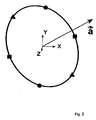
- Fig. 2
- schematisch einen als Kreisbahn ausgebildeten Scanning-Weg, wobei Extrempunkte gekennzeichnet sind, die für die Berechnung des maximalen Betrages der Scanning-Geschwindigkeit verwendet werden,
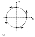
- Fig. 3
- wiederum einen als Kreisbahn ausgebildeten Scanning-Weg, der jedoch in einer durch lediglich zwei Koordinatenachsen aufgespannten Ebene liegt,
- Fig. 4
- die Kreisbahn gemäß
Fig. 2 mit einer schematischen Darstellung von Vektoren, die für die weitere Berechnung der maximalen Scanning-Geschwindigkeit verwendet werden, - Fig. 5
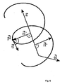
- schematisch einen als Helixbahn ausgebildeten Scanning-Weg, wobei Extrempunkte gekennzeichnet sind, die für die Berechnung des maximalen Betrages der Scanning-Geschwindigkeit verwendet werden,
- Fig. 6
- die Helixbahn gemäß
Fig. 5 mit einer schematischen Darstellung von Vektoren, die für die weitere Berechnung der maximalen Scanning-Geschwindigkeit verwendet werden, und - Fig. 7
- eine Darstellung, die die Zerlegung eines Scanning-Geschwindigkeitsvektors in zwei Komponenten zeigt.
- Fig. 1
- a particularly preferred embodiment of a coordinate measuring machine according to the invention,
- Fig. 2
- schematically a scanning path formed as a circular path, wherein extreme points are used, which are used for the calculation of the maximum amount of the scanning speed,
- Fig. 3
- again a scanning path designed as a circular path, but lying in a plane spanned by only two coordinate axes,
- Fig. 4
- the circular path according to
Fig. 2 with a schematic representation of vectors used for the further calculation of the maximum scanning speed, - Fig. 5
- schematically a scanning path formed as a helical path, wherein extreme points are used, which are used for the calculation of the maximum amount of the scanning speed,
- Fig. 6
- the helix track according to
Fig. 5 with a schematic representation of vectors that are used for the further calculation of the maximum scanning speed, and - Fig. 7
- a representation showing the decomposition of a scanning velocity vector into two components.
Das Koordinatenmessgerät weist eine Basis 25 mit Füßen 27 auf. Die Basis 25 weist in ihrer Mitte eine Werkstückhalterung oder Werkstückauflage 29 auf, auf welcher ein zu vermessendes Werkstück anzuordnen ist. Beidseits der Werkstückhalterung 29 erstrecken sich an der Basis 25 Streben 33, 34 nach oben, welche beidseits der Werkstückhalterung 29 angeordnete, in einer horizontalen Richtung (der Y-Richtung) und parallel zueinander sich erstreckende Längsführungen 35, 36 tragen. Orthogonal zu den Längsführungen 35, 36 erstreckt sich horizontal eine Querführung 37 in X-Richtung, welche an den Längsführungen 35, 36 in Y-Richtung linear verschiebbar gelagert ist. Hierzu ist an einem Ende der Querführung 37 ein Führungsprofil 39 vorgesehen, welches die Längsführung 36 von oben U-förmig umgreift und an dieser beispielsweise mittels Luftkissen geführt ist. Mit ihrem anderen Ende ist die Querführung 37 auf der Oberseite der Längsführung 35 abgestützt und auch gegenüber dieser in Y-Richtung verschiebbar gelagert. Durch einen motorischen Antrieb, welcher von einer Steuerung 31 gesteuert wird, kann die Querführung 37 entlang der Längsführung 36 verschoben werden, wobei eine entsprechende Verschiebestellung in Y-Richtung durch ein Messsystem erfasst wird, welches einen an der Basis festgelegten Maßstab 41 und einen zugehörigen an dem U-Profil 39 festgelegten Sensor 43 zum Ablesen des Maßstabs 41 aufweist.The coordinate measuring machine has a base 25 with
An der Querführung 37 ist ein Führungsprofil 45 in X-Richtung linear verschiebbar gelagert, wobei die Verschiebestellung in X-Richtung ebenfalls durch ein Messsystem erfasst wird, welches hierzu einen an der Querführung 37 angebrachten Maßstab 49 und einen an dem Führungsprofil 45 festgemachten zugehörigen Sensor 51 aufweist. Von der Steuerung 31 wird ein in
An dem Führungsprofil 45 sind zwei weitere mit Abstand voneinander angeordnete Führungsprofile 53 vorgesehen, welche eine sich in Z-Richtung erstreckende Stange 55 über einen ebenfalls von der Steuerung 31 gesteuerten Motor 57 verschiebbar lagern. Die Verschiebestellung der Stange 55 in Z-Richtung wird über einen an der Vertikalführung 53 vorgesehenen Sensor 49 erfasst, der die Position an einem an der Stange 55 festgelegten Maßstab 61 abliest. An einer an einem unteren Ende der Stange 55 vorgesehenen Pinole ist ein Messkopfsystem 63 gehaltert. Das Messkopfsystem kann eine Messkopfvedängerung und/oder ein Messkopfwechselsystem umfassen, um den eigentlichen Messkopf an die Pinole zu koppeln. Ein Tastersystem ist wiederum an den Messkopf gekoppelt, wobei das Tastersystem an den Messkopf starr gekoppelt sein kann. Es kann auch ein Tastenivechselsystem vorgesehen sein, um an den Messkopf verschiedene auswechselbare Tastersysteme zu koppeln. Das Tastersystem kann eine Tasterverfängerung umfassen, welche sich in einem Tasterschaft fortsetzt, an dessen Ende ein Tastelement 64 angebracht ist, welches zum Vermessen der Werkstückoberfläche mit dieser in Kontakt gebracht wird. Das Tastelement 64 kann beispielsweise eine Rubinkugel sein. Das Tastersystem kann auch mehrere Taster umfassen, welche sich beispielsweise an einer Tasterverlängerung quer zueinander erstrecken, um in verschiedene Richtungen orientierte Oberflächen des Werkstücks anzutasten. In der Pinole und dem Messkopf oder einem Messkopfwechselsystem oder einer eingefügten Messkopfverlängerung kann auch ein Drehschwenksystem vorgesehen sein, um eine Orientierung des Messkopfes bezüglich der Pinole zu ändern, so dass auch eine Orientierung des Tasters im Raum änderbar ist, um in verschiedene Richtungen orientierte Oberflächen von Werkstücken anzutasten.On the
Die Steuerung 31 steuert über die Antriebe die Position des Tastelements 64 relativ zu der Werkstückhalterung 29, sie registriert einen Kontakt zwischen dem Tasterelement und der Oberfläche des Werkstücks und sie liest die Messsysteme des Koordinatenmessgeräts 23 aus, um die Koordinaten der Position des Tasterelements 64 relativ zu der Werkstückhalterung 29 möglichst exakt zu messen. Die Steuerung 31 ist in
Unter Bezugnahme auf
Wie bereits erwähnt, steht die Berechnung unter der Bedingung, dass der Betrag der Scanning-Geschwindigkeit bei der Ausführung des Werkstück-Scanning, insbesondere im Fall der Kreisbahn, konstant ist. Die Tatsache, dass die maximal mögliche und/oder zulässige Scanning-Geschwindigkeit berechnet werden soll, führt zu der Forderung, dass für jeden Freiheitsgrad der Bewegung des Tastelements das Maximum der zugehörigen Bewegungsgeschwindigkeitskomponente so weit wie möglich ausgenutzt werden soll.As already mentioned, the calculation is subject to the condition that the amount of the scanning speed during the execution of the workpiece scanning, in particular in the case of the circular path, is constant. The fact that the maximum possible and / or allowable scanning speed is to be calculated leads to the requirement that for each degree of freedom of movement of the probe element, the maximum of the associated motion velocity component should be utilized as far as possible.
In dem folgenden Ausführungsbeispiel hat das Koordinatenmessgerät drei voneinander unabhängige lineare Freiheitsgrade der Bewegung, wobei die Freiheitsgrade den drei Koordinatenachsen X, Y, Z eines kartesischen Koordinatensystems der Messanordnung entsprechen. Unter anderem werden bei der Berechnung der maximalen Scanning-Geschwindigkeit die in Tabelle 1 eingeführten Symbole verwendet.
(Kennzeichnet den Bezug eines beliebigen Vektors
(Kennzeichnet die Komponente eines beliebigen Vektors 

(Indicates the reference of any vector
(Indicates the component of any vector
Auf einem Scanning-Weg kann es Punkte (im Folgenden Extrempunkte genannt, wobei sich "extrem" auf die Geschwindigkeit bezieht) geben, in denen jeweils der maximal mögliche Betrag der Geschwindigkeit der Verfahrachsen wirkt. D.h. Extrempunkte sind Scanning-Punkte, in denen die Bewegungsgeschwindigkeit des Tastelements in einer der drei Koordinatenachsen am größten ist.On a scanning path, there may be points (hereafter referred to as extreme points, where "extreme" refers to the speed) in which the maximum possible amount of the speed of the tracks acts in each case. That Extreme points are scanning points in which the movement speed of the probe element in one of the three coordinate axes is greatest.
Bei einer Kreisbahn gibt es zumindest vier solche Extrempunkte (wenn die Kreisbahn in der durch zwei der Koordinatenachsen aufgespannten Ebene liegt), siehe
In dem Beispiel gemäß
Liegt die Kreisbahn jedoch nicht in einer Ebene, die von lediglich zwei der Koordinatenachsen aufgespannt wird, existieren auch Extrempunkte bezüglich der dritten Richtung, hier der Z-Richtung. Dieser Fall ist in
Bei einem Kreis verhalten sich die zwei Extrempunkte, die auf dieselbe Koordinatenachse bezogen sind, gleich. D.h. die Richtungen der Scanning-Geschwindigkeiten in den beiden Extrempunkten sind dann einander entgegengesetzt. Die Geschwindigkeitsvektoren sind antiparallel. Somit braucht nur ein Extrempunkt pro Achse betrachtet zu werden, z. B. indem lediglich die Beträge der Geschwindigkeitskomponenten betrachtet werden.For a circle, the two extremes that are related to the same coordinate axis behave the same. That is, the directions of the scanning speeds in the two extreme points are then opposite to each other. The velocity vectors are anti-parallel. Thus, only one extreme point per axis needs to be considered, for. By considering only the amounts of the velocity components.
Im Folgenden wird in Bezug auf das Ausführungsbeispiel mit der Kreisbahn eine besonders bevorzugte Ausführungsform des erfindungsgemäßen Verfahrens beschrieben. Der Grundgedanke dieser Ausführungsform liegt in der einfachen Berechnung der Extrempunkte und in der einfachen Bestimmung der maximalen Scanning-Geschwindigkeit durch Vektoroperationen und Auswertung der entscheidenden Vektorkomponenten.In the following, with reference to the exemplary embodiment with the circular path, a particularly preferred embodiment of the method according to the invention will be described. The basic idea of this embodiment lies in the simple calculation of the extreme points and in the simple determination of the maximum scanning speed by vector operations and evaluation of the crucial vector components.
Die Einheitsvektoren (d: h. der Betrag der Vektoren ist gleich eins)
Mit diesen drei Einheitsvektoren lassen sich in der im Folgenden beschriebenen Weise einfach die Extrempunkte berechnen.These three unit vectors can be used to simply calculate the extreme points in the manner described below.
Die Einheitsvektoren lauten: ![]()
![]()
![]()
![]()
![]()
![]()
Der Achsenvektor 
Für jede Koordinatenachse gilt somit (in Gleichung [1] wird für I der jeweilige Index X, Y, Z eingesetzt): ![]()
![]()
![]()
![]()
![]()
![]()
Somit sind, aus Sicht der Symmetrieachse, die Richtungen bekannt, in denen die Extrempunkte liegen. Losgelöst von dem konkreten Ausführungsbeispiel der Kreisbahn kann es im Allgemeinen vorkommen, dass in der Richtung eines oder mehrerer der Vektoren
Wird das Kreuzprodukt zwischen einem Einheitsvektor und dem Achsenvektor 
d.h. der Achsenvektor
ie the axis vector
Alternativ zu der Überprüfung, ob das Kreuzprodukt für einen der Einheitsvektoren gleich Null wird, kann das Skalarprodukt zwischen den Einheitsvektoren 
Im Fall der Kreisbahn können dann für die Berechnung der beiden auf die anderen Koordinatenachsen bezogenen Richtungssektoren ![]()
![]()
Die Extrempunkte 
Das Kreuzprodukt zwischen dem Achsenvektor 
Für jede Achse gilt somit: ![]()
![]()
![]()
![]()
![]()
![]()
Diese Vektoren
Im Folgenden wird nun aus den ermittelten Tangentenvektoren
Hierzu werden die Komponenten 
Die Komponenten
Die Komponenten
Nur der Betrag der Geschwindigkeitskomponente
Da tI den Geschwindigkeitsvektor für einen Extrempunkt bezüglich der Achse I darstellt, wird für die Bestimmung des Ausnutzungsrades ηIk nur die Komponente benötigt, für die folgende Bedingung gilt: ![]()
![]()
Für die Ermittlung der maximalen Scanning-Geschwindigkeit ist ferner nur die (betragsmäßig) größte Komponente
Für jede Achse gilt somit nur ein maximaler Ausnutzungsgrad: ![]()
![]()
![]()
![]()
![]()
![]()
Da der Vektor
Die maximale Scanning-Geschwindigkeit vScanMaxk in der Achse wird in dem bevorzugten Ausführungsbeispielen dadurch berechnet, dass für jede Achse der Kehrwert des maximalen Ausnutzungsgrades ηIk mit der maximal zulässigen Achsgeschwindigkeit vMaxk des Koordinatenmessgeräts bzw. des Tastelements multipliziert wird. Durch die Multiplikation der Achsgeschwindigkeit werden eventuell unterschiedliche Geschwindigkeiten in den Achsen berücksichtigt. 
Aus den drei berechneten Werten vScanMaxk wird nun das Minimum bestimmt. Dies ist erforderlich, da die Geschwindigkeit in dem Extrempunkt mit dem niedrigsten Geschwindigkeitsbetrag die Scanning-Geschwindigkeit vScanBahn des Scanning-Weges begrenzt. ![]()
![]()
Zuvor wurde verschiedentlich auf den Anwendungsfall einer Kreisbahn eingegangen. Im Folgenden wird auf einen weiteren in der Praxis häufig vorkommenden Fall eingegangen, dem Scanning-Weg in Form einer Helix. Dieser Fall kommt insbesondere dann vor, wenn eine zylinderförmige Oberfläche abgetastet wird. Es wird im Folgenden lediglich auf Unterschiede und Besonderheiten zu der zuvor beschriebenen Ausführungsform eingegangen.Previously, the application of a circular path was discussed several times. In the following, we will discuss a further case that frequently occurs in practice, the scanning path in the form of a helix. This case occurs in particular when a cylindrical surface is scanned. In the following, only differences and special features relating to the embodiment described above will be discussed.
Die Extrempunkte werden bevorzugt in derselben Weise, durch Bildung des Kreuzprodukts des Achsenvektors
Ergebnisvektor
Zusätzlich zu den drei in
Ergebnisvektoren 


Wird das Kreuzprodukt zwischen den Einheitsvektoren 
Dies kann wiederum alternativ durch Bildung des Skalarproduktes festgestellt werden (siehe oben).This can again be determined alternatively by formation of the scalar product (see above).
Bei der Zylinderbahn lässt sich die Scanning-Geschwindigkeit
Der achsparallele Anteil
Das Kreuzprodukt zwischen dem Achsenvektor ![]()
![]()
Dieser Schritt des Verfahrens ist daher gleich wie im Fall der Kreisbahn. Es gilt somit: 
In 
Alle achsparallelen Anteile ![]()
![]()
Für weitere Berechnungen wird der Vektor 
Die Richtung der Scanninggeschwindigkeit
Um die Steigung der Helix zu berücksichtigen, muss der tangentiale Anteil
Die Vektor der Scanning-Geschwindigkeit 
Für weitere Berechnungen wird der Vektor 
Es soll bei dieser Gelegenheit auf die Analogie zu der Berechnung im Fall der Kreisbahn hingewiesen werden: Wird die Ganghöhe h = 0 , ergibt sich unmittelbar: ![]()
![]()
Umgekehrt folgt, dass die weitere, oben bereits beschriebene Verfahrensweise zur Berechnung der maximalen Scanning-Geschwindigkeit in der gleichen Weise für die Helix angewendet werden kann, wobei jedoch an Stelle des Tangentenvektors
Im Folgenden wird wiederum für einen Scanning-Weg in Form einer Helix ein Zahlenbeispiel für die Berechnung der maximalen Scanning-Geschwindigkeit beschrieben. Die verwendeten Symbole sind dieselben wie oben eingeführt. Das Zahlenbeispiel geht von folgender Geometrie und Lage der Helix im kartesischen Koordinatensystem aus. Der Achsenvektor hat folgende Koordinaten: 
Der Durchmesser D eines Zylinders, dessen Oberfläche die Helix umläuft, beträgt 20 mm, die Höhe h des Zylinders 100 mm und die Gangzahl der Helix über diese Höhe ist 2.The diameter D of a cylinder whose surface revolves around the helix is 20 mm, the height h of the cylinder is 100 mm, and the number of turns of the helix above this height is 2.
Die maximalen Beträge der Geschwindigkeiten der drei Lineareachsen in X-, Y- und Z-Richtung sind jeweils 300 mm/s.The maximum speeds of the three linear axes in the X, Y and Z directions are each 300 mm / s.
Für die Ergebnisvektoren 


Dafür lauten die Ergebnisse der bereits auf Eins normierten tangentialen Anteile 


Da keines der Kreuzprodukte gleich
Der achsparallele Anteil der Scanning-Geschwindigkeit berechnet sich zu: 
Daraus erhält man die folgenden Geschwindigkeitsvektoren in den Extrempunkten, wobei auch diese Geschwindigkeitsvektoren bereits auf Eins normiert sind: 


Daraus ergeben sich die relevanten Ausnutzungsgrade: 


wobei bereits für jede der Koordinatenachsen X, Y, Z das Maximum der Auswertungskomponenten gebildet und der Betrag berechnet wurden.This results in the relevant utilization rates:
where already for each of the coordinate axes X, Y, Z, the maximum of the evaluation components were formed and the amount was calculated.
Die maximalen Scanning-Geschwindigkeiten für die einzelnen Koordinatenachsen werden nun berechnet: 


und deren Minimum gebildet: ![]()
and their minimum formed: ![]()
Das Gesamtergebnis des maximalen Betrages der Scanning-Geschwindigkeit lautet somit: 329,6 mm/s. Sie wird durch die Geschwindigkeit in einem der beiden bezüglich der X-Achse bestimmten Extrempunkte limitiert.The total result of the maximum amount of scanning speed is thus: 329.6 mm / s. It is limited by the speed in one of the two extremes determined with respect to the x-axis.
Claims (10)
- Method for contacting a workpiece surface with the aid of a coordinate measuring machine (23),- in which a probe element (64) of the coordinate measuring machine (23) is brought into contact with the surface, and the probe element (64) is moved along the surface in a scanning movement while contact is maintained,- in which the coordinate measuring machine (23) has a plurality of mutually independent degrees of freedom, for example, degrees of freedom of linear axes, of the possible movements of the probe element with reference to the workpiece, and in which there are defined for the degrees of freedom maximum speed magnitudes that describe the maximum of a movement speed component of the probe element (64) referred to the respective degree of freedom,- in which for a planned scanning of the workpiece there is, or has been, prescribed, an estimated scanning path on which the probe element (64) is to move during scanning, and in which the actual scanning path can differ from the estimated scanning path as a function of the actual measurements of the workpiece,characterized in that by taking account of the maximum speed magnitudes for the various degrees of freedom, a maximum magnitude of the scanning speed is determined at which the estimated scanning path can be traversed at a constant magnitude of the speed of the probe element (64).
- Method according to Claim 1, in which at least one of the degrees of freedom is a degree of freedom of a linear axis of the coordinate measuring machine (23), in which account is being taken when determining the maximum magnitude of the scanning speed of extreme points on the estimated scanning path that have a local maximum of the derivative of the magnitude of a coordinate with respect to the path, in which the coordinate is a spatial coordinate that is defined with reference to a coordinate axis that is the linear axis or that runs parallel to the linear axis, and in which the maximum magnitude of the scanning speed is fixed such that the magnitude of the speed component with reference to the coordinate axis does not exceed the maximum speed magnitude of the degree of freedom at any of the extreme points determined.
- Method according to Claim 1 or 2, in which at least a portion of the estimated scanning path has a round profile, in particular having the shape of a circular arc, helix, spiral or ellipse, or being oval.
- Method according to Claim 2 and Claim 3, in which there is defined for the round profile a rectilinear axis that is a rotational symmetry axis of the profile or is a projection of the profile on to a plane perpendicular to the rotational symmetry axis, and in which the extreme points are taken into account by forming the cross product of a symmetry axis vector in the direction of the rotational symmetry axis with a linear axis vector in the direction of the linear axis.
- Method according to Claim 2 and according to one of Claims 3 to 4, in which the extreme points are taken into account for all degrees of freedom, in which for each of the extreme points a tangent vector is formed that runs in the direction of the tangent at the extreme point, and in which in each case only the component of the tangent vector is used as evaluation component to calculate the maximum magnitude of the scanning speed, which is defined with reference to the degree of freedom, for which the extreme point was determined.
- Method according to Claim 5, in which all the tangent vectors are normalized to an equal magnitude, and in which the maximum magnitude of the scanning speed is determined from the evaluation components.
- Method according to Claim 6, in which it is determined from the evaluation components of the normalized tangent vectors and the maximum speed magnitudes for the respectively assigned degrees of freedom which of the maximum speed magnitudes of the degrees of freedom limits the maximum magnitude of the scanning speed.
- Method according to Claim 7, in which the magnitudes of all evaluation components of the same degree of freedom are formed, the reciprocal values of the magnitudes are respectively multiplied by the maximum speed magnitude of the assigned degree of freedom and the minimum of the multiplication results is used to determine the maximum magnitude of the scanning speed.
- Coordinate measuring machine (23) having a probe element (64) for contacting a workpiece surface, in which the coordinate measuring machine (23) is designed to be brought into contact with the surface and to be moved along the surface in a scanning movement while contact is maintained, in which the coordinate measuring machine (23) has a plurality of mutually independent degrees of freedom, for example, degrees of freedom of linear axes, of the possible movements of the probe element (64) with reference to the workpiece, and in which there are defined for the degrees of freedom maximum speed magnitudes that describe the maximum of a movement speed component of the probe element (64) referred to the respective degree of freedom, in which the coordinate measuring machine (23) has a speed determining device (31) that is configured to evaluate an estimated scanning path for a planned scanning of the workpiece, in which the probe element (64) is to move during scanning on the scanning path, in which the actual scanning path can differ from the estimated scanning path as a function of actual measurements of the workpiece, characterized in that the speed determining device (31) is configured to determine, taking account of the maximum speed magnitudes for the various degrees of freedom, a maximum magnitude of the scanning speed at which the estimated scanning path can be traversed at a constant magnitude of the speed of the probe element (64).
- Coordinate measuring machine according to the preceding claim, in which the speed determining device (31) is configured to execute the method according to one of the Method Claims 2 to 8.
Applications Claiming Priority (2)
| Application Number | Priority Date | Filing Date | Title |
|---|---|---|---|
| DE102006019382A DE102006019382A1 (en) | 2006-04-24 | 2006-04-24 | Scanning a surface with a coordinate measuring machine |
| PCT/EP2007/003724 WO2007122012A1 (en) | 2006-04-24 | 2007-04-19 | Scanning a surface using a coordinate measurement device |
Publications (2)
| Publication Number | Publication Date |
|---|---|
| EP2010864A1 EP2010864A1 (en) | 2009-01-07 |
| EP2010864B1 true EP2010864B1 (en) | 2009-09-23 |
Family
ID=38197791
Family Applications (1)
| Application Number | Title | Priority Date | Filing Date |
|---|---|---|---|
| EP07724654A Active EP2010864B1 (en) | 2006-04-24 | 2007-04-19 | Scanning a surface using a coordinate measuring machine |
Country Status (5)
| Country | Link |
|---|---|
| US (1) | US7644507B2 (en) |
| EP (1) | EP2010864B1 (en) |
| JP (1) | JP5053361B2 (en) |
| DE (2) | DE102006019382A1 (en) |
| WO (1) | WO2007122012A1 (en) |
Families Citing this family (12)
| Publication number | Priority date | Publication date | Assignee | Title |
|---|---|---|---|---|
| DE102005032749A1 (en) * | 2005-07-13 | 2007-01-18 | Carl Zeiss Industrielle Messtechnik Gmbh | Method for probing a workpiece with a coordinate measuring machine and coordinate measuring machines |
| BRPI0621582A2 (en) * | 2006-04-06 | 2011-12-13 | Hexagon Metrology Spa | horizontal arm coordinate measuring machine |
| DE102006019382A1 (en) | 2006-04-24 | 2007-10-25 | Carl Zeiss Industrielle Messtechnik Gmbh | Scanning a surface with a coordinate measuring machine |
| GB2437982B (en) * | 2006-05-08 | 2011-07-27 | Taylor Hobson Ltd | Metrological apparatus |
| CN101458058B (en) * | 2007-12-12 | 2010-09-29 | 鸿富锦精密工业(深圳)有限公司 | Measuring device |
| US8379917B2 (en) | 2009-10-02 | 2013-02-19 | DigitalOptics Corporation Europe Limited | Face recognition performance using additional image features |
| JP5697416B2 (en) * | 2010-11-24 | 2015-04-08 | キヤノン株式会社 | Contact-type shape measuring device |
| MY174861A (en) * | 2011-02-10 | 2020-05-19 | Bruker Nano Inc | Nanomechanical testing system |
| EP2739935B1 (en) * | 2011-08-03 | 2015-10-21 | Carl Zeiss Industrielle Messtechnik GmbH | Co-ordinate measuring device for measuring a workpiece |
| DE102013216093B4 (en) * | 2013-08-14 | 2016-06-02 | Carl Zeiss Industrielle Messtechnik Gmbh | Reduction of errors of a rotating device, in particular for the determination of coordinates of a workpiece or the machining of a workpiece |
| DE102019110508A1 (en) * | 2019-04-23 | 2020-10-29 | Carl Zeiss Industrielle Messtechnik Gmbh | Method for controlling a coordinate measuring machine and a coordinate measuring machine |
| CN112050767A (en) * | 2020-08-28 | 2020-12-08 | 南京昆程仕科技有限公司 | Miniature coordinate measuring machine for education edition |
Family Cites Families (23)
| Publication number | Priority date | Publication date | Assignee | Title |
|---|---|---|---|---|
| DE3523188A1 (en) * | 1985-06-28 | 1987-01-08 | Zeiss Carl Fa | CONTROL FOR COORDINATE MEASURING DEVICES |
| GB8605324D0 (en) * | 1986-03-04 | 1986-04-09 | Rank Taylor Hobson Ltd | Metrological apparatus |
| JPS63253206A (en) * | 1987-04-10 | 1988-10-20 | Mitsubishi Electric Corp | Shape measuring instrument |
| US4866643A (en) * | 1987-10-09 | 1989-09-12 | Brown & Sharpe Manufacturing Company | Method for automatic compensation of probe offset in a coordinate measuring machine |
| DE4212455C3 (en) * | 1992-04-14 | 2001-09-06 | Zeiss Carl | Method for measuring shaped elements on a coordinate measuring machine |
| DE4245012B4 (en) * | 1992-04-14 | 2004-09-23 | Carl Zeiss | Method for measuring shaped elements on a coordinate measuring machine |
| JP3062412B2 (en) * | 1994-12-20 | 2000-07-10 | 株式会社ミツトヨ | Scanning measurement control method |
| DE19525592A1 (en) * | 1995-07-13 | 1997-01-16 | Zeiss Carl Fa | Procedure for coordinate measurement on workpieces |
| DE19529547A1 (en) * | 1995-08-11 | 1997-02-13 | Zeiss Carl Fa | Method for controlling coordinate measuring machines |
| JPH09280834A (en) * | 1996-04-10 | 1997-10-31 | Ricoh Co Ltd | Shape measuring device |
| EP0849653B1 (en) * | 1996-12-21 | 2004-04-28 | Carl Zeiss | Control method for a coordinate measuring device and coordinate measuring device |
| DE19712029A1 (en) * | 1997-03-21 | 1998-09-24 | Zeiss Carl Fa | Method for controlling coordinate measuring machines according to target data |
| JP4038334B2 (en) * | 1998-08-28 | 2008-01-23 | 株式会社ミツトヨ | Apparatus and method for analyzing part program and creating part program in coordinate and surface texture measurement |
| GB9907868D0 (en) | 1999-04-08 | 1999-06-02 | Renishaw Plc | Method of calibrating a scanning system |
| JP3880030B2 (en) * | 2000-03-17 | 2007-02-14 | 株式会社ミツトヨ | V-groove shape measuring method and apparatus |
| DE10050795C2 (en) * | 1999-12-23 | 2002-11-07 | Klingelnberg Gmbh | Method and device for scanning on a coordinate measuring machine |
| JP4170567B2 (en) * | 2000-07-07 | 2008-10-22 | 株式会社ソディック | Machine tool moving device and method of controlling machine tool moving device |
| DE10214490B4 (en) * | 2002-03-26 | 2010-12-02 | Carl Zeiss Industrielle Messtechnik Gmbh | Method for correcting guide errors in a coordinate measuring machine |
| JP2005009917A (en) * | 2003-06-17 | 2005-01-13 | Mitsutoyo Corp | Surface copying measuring instrument, surface copying measuring method, surface copying measuring program, and recording medium |
| JP4782990B2 (en) * | 2004-05-31 | 2011-09-28 | 株式会社ミツトヨ | Surface scanning measuring device, surface scanning measuring method, surface scanning measuring program, and recording medium |
| DE102004038416B4 (en) * | 2004-07-30 | 2014-02-06 | Carl Zeiss Industrielle Messtechnik Gmbh | Method for determining spatial coordinates of a measuring point on a measuring object and corresponding coordinate measuring machine |
| DE102005032749A1 (en) | 2005-07-13 | 2007-01-18 | Carl Zeiss Industrielle Messtechnik Gmbh | Method for probing a workpiece with a coordinate measuring machine and coordinate measuring machines |
| DE102006019382A1 (en) | 2006-04-24 | 2007-10-25 | Carl Zeiss Industrielle Messtechnik Gmbh | Scanning a surface with a coordinate measuring machine |
-
2006
- 2006-04-24 DE DE102006019382A patent/DE102006019382A1/en not_active Ceased
-
2007
- 2007-04-19 WO PCT/EP2007/003724 patent/WO2007122012A1/en active Application Filing
- 2007-04-19 DE DE502007001594T patent/DE502007001594D1/en active Active
- 2007-04-19 JP JP2009505801A patent/JP5053361B2/en active Active
- 2007-04-19 EP EP07724654A patent/EP2010864B1/en active Active
-
2008
- 2008-08-11 US US12/189,252 patent/US7644507B2/en active Active
Also Published As
| Publication number | Publication date |
|---|---|
| US20080307662A1 (en) | 2008-12-18 |
| DE102006019382A1 (en) | 2007-10-25 |
| US7644507B2 (en) | 2010-01-12 |
| JP5053361B2 (en) | 2012-10-17 |
| JP2009534636A (en) | 2009-09-24 |
| WO2007122012A1 (en) | 2007-11-01 |
| EP2010864A1 (en) | 2009-01-07 |
| DE502007001594D1 (en) | 2009-11-05 |
Similar Documents
| Publication | Publication Date | Title |
|---|---|---|
| EP2010864B1 (en) | Scanning a surface using a coordinate measuring machine | |
| EP2834595B1 (en) | Method and apparatus for reducing errors of a rotating device when determining coordinates of a workpiece or when machining a workpiece | |
| EP3240994B1 (en) | Detecting geometric movement guidance deviations in a coordinate measuring device or a machine tool | |
| DE602005004092T2 (en) | Device for measuring the surface roughness or contour of an object | |
| DE102016107397B4 (en) | PATH DISPLAY DEVICE FOR DISPLAYING THE PATH OF A TOOL AXIS | |
| EP3033596A1 (en) | Reducing errors of a rotary device, in particular for the determination of coordinates of a workpiece or the machining of a workpiece | |
| DE102013008755B4 (en) | Offline programming system | |
| DE102017008570A1 (en) | Machine tool and method for smoothing a workpiece | |
| EP0026274B1 (en) | Tooth profile testing device and method of testing tooth profiles | |
| EP2561311B2 (en) | Operation of a coordinate measuring machine or a machine tool | |
| EP1708828A1 (en) | Method for determining the co-ordinates of a workpiece | |
| EP1947538B1 (en) | Method for controlling a moveable tool, input device and processing machine | |
| EP2755095B1 (en) | Method for controlling a measuring process by means of virtual interfaces | |
| DE102007011603B4 (en) | Method and device for determining the geometry data of a conical measurement object | |
| EP2679962B1 (en) | Position measuring device | |
| DE102018201322A1 (en) | Method for controlling a shape measuring device | |
| EP3835900B1 (en) | Method and device for testing workpieces | |
| EP0962843B1 (en) | Method for non-linear display of tool paths of numerically controlled machine tool | |
| EP1893941B1 (en) | Method and device for determining geometric parameters of a conical object to be measured | |
| DE102017221737B4 (en) | Method and system for evaluating a predetermined surface area of a test specimen detected by a measuring device | |
| DE102021102619A1 (en) | CONTROL UNIT AND CONTROL METHOD | |
| DE3823993A1 (en) | Method for coordinate measurement on workpieces | |
| DE102020208567A1 (en) | Calibration of a reference body for determining the guidance error of a machine axis | |
| DE3538551C1 (en) | Auxiliary reference device for, in particular, three-dimensional measurement and/or marking apparatuses | |
| DE102010011841B4 (en) | Method for validating a measurement result of a coordinate measuring machine |
Legal Events
| Date | Code | Title | Description |
|---|---|---|---|
| PUAI | Public reference made under article 153(3) epc to a published international application that has entered the european phase |
Free format text: ORIGINAL CODE: 0009012 |
|
| 17P | Request for examination filed |
Effective date: 20080529 |
|
| AK | Designated contracting states |
Kind code of ref document: A1 Designated state(s): AT BE BG CH CY CZ DE DK EE ES FI FR GB GR HU IE IS IT LI LT LU LV MC MT NL PL PT RO SE SI SK TR |
|
| AX | Request for extension of the european patent |
Extension state: AL BA HR MK RS |
|
| RIN1 | Information on inventor provided before grant (corrected) |
Inventor name: FUCHS, ANDREAS Inventor name: DEEG, HERMANN Inventor name: BURGER, JOCHEN |
|
| GRAP | Despatch of communication of intention to grant a patent |
Free format text: ORIGINAL CODE: EPIDOSNIGR1 |
|
| RTI1 | Title (correction) |
Free format text: SCANNING A SURFACE USING A COORDINATE MEASURING MACHINE |
|
| DAX | Request for extension of the european patent (deleted) | ||
| RBV | Designated contracting states (corrected) |
Designated state(s): DE FR GB IT |
|
| GRAS | Grant fee paid |
Free format text: ORIGINAL CODE: EPIDOSNIGR3 |
|
| GRAA | (expected) grant |
Free format text: ORIGINAL CODE: 0009210 |
|
| AK | Designated contracting states |
Kind code of ref document: B1 Designated state(s): DE FR GB IT |
|
| REG | Reference to a national code |
Ref country code: GB Ref legal event code: FG4D Free format text: NOT ENGLISH |
|
| REF | Corresponds to: |
Ref document number: 502007001594 Country of ref document: DE Date of ref document: 20091105 Kind code of ref document: P |
|
| PLBE | No opposition filed within time limit |
Free format text: ORIGINAL CODE: 0009261 |
|
| STAA | Information on the status of an ep patent application or granted ep patent |
Free format text: STATUS: NO OPPOSITION FILED WITHIN TIME LIMIT |
|
| 26N | No opposition filed |
Effective date: 20100624 |
|
| PG25 | Lapsed in a contracting state [announced via postgrant information from national office to epo] |
Ref country code: IT Free format text: LAPSE BECAUSE OF NON-PAYMENT OF DUE FEES Effective date: 20100419 |
|
| PGFP | Annual fee paid to national office [announced via postgrant information from national office to epo] |
Ref country code: FR Payment date: 20130515 Year of fee payment: 7 |
|
| REG | Reference to a national code |
Ref country code: FR Ref legal event code: ST Effective date: 20141231 |
|
| PG25 | Lapsed in a contracting state [announced via postgrant information from national office to epo] |
Ref country code: FR Free format text: LAPSE BECAUSE OF NON-PAYMENT OF DUE FEES Effective date: 20140430 |
|
| P01 | Opt-out of the competence of the unified patent court (upc) registered |
Effective date: 20230525 |
|
| PGFP | Annual fee paid to national office [announced via postgrant information from national office to epo] |
Ref country code: IT Payment date: 20230426 Year of fee payment: 17 Ref country code: DE Payment date: 20230420 Year of fee payment: 17 |
|
| PGFP | Annual fee paid to national office [announced via postgrant information from national office to epo] |
Ref country code: GB Payment date: 20230419 Year of fee payment: 17 |