EP2010830B1 - Radiation concentrating device - Google Patents
Radiation concentrating device Download PDFInfo
- Publication number
- EP2010830B1 EP2010830B1 EP07724477A EP07724477A EP2010830B1 EP 2010830 B1 EP2010830 B1 EP 2010830B1 EP 07724477 A EP07724477 A EP 07724477A EP 07724477 A EP07724477 A EP 07724477A EP 2010830 B1 EP2010830 B1 EP 2010830B1
- Authority
- EP
- European Patent Office
- Prior art keywords
- mirror
- base
- radiation
- receiving element
- support
- Prior art date
- Legal status (The legal status is an assumption and is not a legal conclusion. Google has not performed a legal analysis and makes no representation as to the accuracy of the status listed.)
- Not-in-force
Links
- 230000005855 radiation Effects 0.000 title claims abstract description 31
- 230000008878 coupling Effects 0.000 claims abstract description 9
- 238000010168 coupling process Methods 0.000 claims abstract description 9
- 238000005859 coupling reaction Methods 0.000 claims abstract description 9
- 230000005670 electromagnetic radiation Effects 0.000 claims abstract description 5
- 239000004020 conductor Substances 0.000 claims abstract description 3
- 239000000463 material Substances 0.000 claims description 8
- 230000000295 complement effect Effects 0.000 claims description 4
- 229910010293 ceramic material Inorganic materials 0.000 claims description 2
- 239000002131 composite material Substances 0.000 claims description 2
- 239000002826 coolant Substances 0.000 claims description 2
- 239000007788 liquid Substances 0.000 claims description 2
- 238000003754 machining Methods 0.000 claims description 2
- 239000007769 metal material Substances 0.000 claims description 2
- 238000005459 micromachining Methods 0.000 claims description 2
- 238000011084 recovery Methods 0.000 claims description 2
- 238000004381 surface treatment Methods 0.000 claims description 2
- 238000009825 accumulation Methods 0.000 description 2
- 230000004075 alteration Effects 0.000 description 2
- 238000005516 engineering process Methods 0.000 description 2
- 238000002834 transmittance Methods 0.000 description 2
- 239000012530 fluid Substances 0.000 description 1
- 238000003780 insertion Methods 0.000 description 1
- 230000037431 insertion Effects 0.000 description 1
- 238000004519 manufacturing process Methods 0.000 description 1
- 238000012986 modification Methods 0.000 description 1
- 230000004048 modification Effects 0.000 description 1
- 230000003595 spectral effect Effects 0.000 description 1
Images
Classifications
-
- G—PHYSICS
- G02—OPTICS
- G02B—OPTICAL ELEMENTS, SYSTEMS OR APPARATUS
- G02B19/00—Condensers, e.g. light collectors or similar non-imaging optics
- G02B19/0004—Condensers, e.g. light collectors or similar non-imaging optics characterised by the optical means employed
- G02B19/0019—Condensers, e.g. light collectors or similar non-imaging optics characterised by the optical means employed having reflective surfaces only (e.g. louvre systems, systems with multiple planar reflectors)
- G02B19/0023—Condensers, e.g. light collectors or similar non-imaging optics characterised by the optical means employed having reflective surfaces only (e.g. louvre systems, systems with multiple planar reflectors) at least one surface having optical power
-
- F—MECHANICAL ENGINEERING; LIGHTING; HEATING; WEAPONS; BLASTING
- F24—HEATING; RANGES; VENTILATING
- F24S—SOLAR HEAT COLLECTORS; SOLAR HEAT SYSTEMS
- F24S23/00—Arrangements for concentrating solar-rays for solar heat collectors
- F24S23/70—Arrangements for concentrating solar-rays for solar heat collectors with reflectors
- F24S23/71—Arrangements for concentrating solar-rays for solar heat collectors with reflectors with parabolic reflective surfaces
-
- F—MECHANICAL ENGINEERING; LIGHTING; HEATING; WEAPONS; BLASTING
- F24—HEATING; RANGES; VENTILATING
- F24S—SOLAR HEAT COLLECTORS; SOLAR HEAT SYSTEMS
- F24S25/00—Arrangement of stationary mountings or supports for solar heat collector modules
- F24S25/40—Arrangement of stationary mountings or supports for solar heat collector modules using plate-like mounting elements, e.g. profiled or corrugated plates; Plate-like module frames
-
- F—MECHANICAL ENGINEERING; LIGHTING; HEATING; WEAPONS; BLASTING
- F24—HEATING; RANGES; VENTILATING
- F24S—SOLAR HEAT COLLECTORS; SOLAR HEAT SYSTEMS
- F24S25/00—Arrangement of stationary mountings or supports for solar heat collector modules
- F24S25/60—Fixation means, e.g. fasteners, specially adapted for supporting solar heat collector modules
- F24S25/63—Fixation means, e.g. fasteners, specially adapted for supporting solar heat collector modules for fixing modules or their peripheral frames to supporting elements
- F24S25/632—Side connectors; Base connectors
-
- G—PHYSICS
- G02—OPTICS
- G02B—OPTICAL ELEMENTS, SYSTEMS OR APPARATUS
- G02B19/00—Condensers, e.g. light collectors or similar non-imaging optics
- G02B19/0033—Condensers, e.g. light collectors or similar non-imaging optics characterised by the use
- G02B19/0038—Condensers, e.g. light collectors or similar non-imaging optics characterised by the use for use with ambient light
- G02B19/0042—Condensers, e.g. light collectors or similar non-imaging optics characterised by the use for use with ambient light for use with direct solar radiation
-
- F—MECHANICAL ENGINEERING; LIGHTING; HEATING; WEAPONS; BLASTING
- F24—HEATING; RANGES; VENTILATING
- F24S—SOLAR HEAT COLLECTORS; SOLAR HEAT SYSTEMS
- F24S23/00—Arrangements for concentrating solar-rays for solar heat collectors
- F24S23/70—Arrangements for concentrating solar-rays for solar heat collectors with reflectors
- F24S2023/87—Reflectors layout
- F24S2023/872—Assemblies of spaced reflective elements on common support, e.g. Fresnel reflectors
-
- F—MECHANICAL ENGINEERING; LIGHTING; HEATING; WEAPONS; BLASTING
- F24—HEATING; RANGES; VENTILATING
- F24S—SOLAR HEAT COLLECTORS; SOLAR HEAT SYSTEMS
- F24S25/00—Arrangement of stationary mountings or supports for solar heat collector modules
- F24S25/60—Fixation means, e.g. fasteners, specially adapted for supporting solar heat collector modules
- F24S2025/6007—Fixation means, e.g. fasteners, specially adapted for supporting solar heat collector modules by using form-fitting connection means, e.g. tongue and groove
-
- G—PHYSICS
- G02—OPTICS
- G02B—OPTICAL ELEMENTS, SYSTEMS OR APPARATUS
- G02B7/00—Mountings, adjusting means, or light-tight connections, for optical elements
- G02B7/18—Mountings, adjusting means, or light-tight connections, for optical elements for prisms; for mirrors
- G02B7/182—Mountings, adjusting means, or light-tight connections, for optical elements for prisms; for mirrors for mirrors
- G02B7/183—Mountings, adjusting means, or light-tight connections, for optical elements for prisms; for mirrors for mirrors specially adapted for very large mirrors, e.g. for astronomy, or solar concentrators
-
- Y—GENERAL TAGGING OF NEW TECHNOLOGICAL DEVELOPMENTS; GENERAL TAGGING OF CROSS-SECTIONAL TECHNOLOGIES SPANNING OVER SEVERAL SECTIONS OF THE IPC; TECHNICAL SUBJECTS COVERED BY FORMER USPC CROSS-REFERENCE ART COLLECTIONS [XRACs] AND DIGESTS
- Y02—TECHNOLOGIES OR APPLICATIONS FOR MITIGATION OR ADAPTATION AGAINST CLIMATE CHANGE
- Y02E—REDUCTION OF GREENHOUSE GAS [GHG] EMISSIONS, RELATED TO ENERGY GENERATION, TRANSMISSION OR DISTRIBUTION
- Y02E10/00—Energy generation through renewable energy sources
- Y02E10/40—Solar thermal energy, e.g. solar towers
- Y02E10/47—Mountings or tracking
Definitions
- the present invention relates to a radiation concentrating device.
- Radiation concentrating devices are currently known particularly for use in the provision of solar or photovoltaic panels.
- the function of concentrating element is performed by a Fresnel lens or variations thereof.
- the Fresnel lens is arranged between the sunlight source and the focal point of the photovoltaic cell.
- This first type of Fresnel-lens concentrating device generally entails important energy losses between 10% and 20% due to limited transmittance.
- the precision of the focus generated by a Fresnel lens is limited to a few spectral lines and is affected by substantial chromatic aberration which impairs the efficiency of the concentrating device; in order to obviate this problem, generally the dimensions of the receiver (sensor or transducer) associated with the lens are increased, with a consequent overall increase in the production costs of the device.
- a second type of concentrating device has a parabolic mirror with a longitudinal focus, i.e., a focus which is distributed along a line or band which is substantially straight, and therefore requires solar cells which are assembled in mutually adjacent rows along the directrix of the focus, with consequent problems linked to dissipation of the beat accumulated by the cells and by the supports on which they are mounted.
- the concentrating element, mirror or Fresnel lens, and the receiving element are mounted separately on separate supports, which must be then mutually positioned laboriously and with the appropriate skill in order to allow correct redirection of the radiation toward the active area of the receiving element.
- Examples of solar radiation concentrator devices are available from the documents US 4 771 764 , US 6 593 038 , WO 2006/000834 and US 4 315 500 .
- the aim of the present invention is to provide a radiation concentrating device which is capable of obviating the drawbacks shown by known types of concentrating device.
- an object of the present invention is to provide a concentrating device which has a higher efficiency than known devices.
- Another object of the present invention is to provide a concentrating device in which the heat accumulation can be dissipated more efficiently than in known types of device.
- Another object of the present invention is to provide a concentrating device which can be assembled more rapidly and at least as accurately as known types of concentrating device.
- a further object of the present invention is to provide a concentrating device particularly but not exclusively adapted for providing solar or photovoltaic panels.
- a still further object of the present invention is to provide a radiation concentrating device which can be manufactured with known systems and technologies.
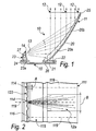
- a radiation concentrating device is generally designated by the reference numeral 10 in its first embodiment.
- the concentrating device 10 comprises, in its minimum configuration, a substantially parabolic mirror 11, which is designed to reflect the energy radiation or electromagnetic radiation that reaches it, designated schematically by lines 12, so that it converges toward an active area 13 of a receiving element 14 arranged in front.
- the active area 13 is interposed between the focal point of the mirror 11 and the mirror 11 itself.
- the substantially parabolic mirror 11 is shaped like a sector of a paraboloid formed by the rotation of a parabola about its own axis of symmetry.
- the mirror 11 and the receiving element 14 are fixed by way of coupling means, described in greater detail hereinafter, to a same base 15.
- the active area 13 of the receiving element 14 has a transverse dimension A which is smaller than a transverse dimension B of the mirror 11 arranged in front.
- the active area 13 is substantially quadrangular and has a much smaller transverse dimension A than the corresponding transverse dimension B of the mirror 11, which also has a rectangular profile in plan view.
- the active receiving area 13 is such as to collect the radiation reflected by the mirror 11, which is in any case made to converge by the mirror 11 toward a region which is contained in the neighborhood of the central axis of the mirror 11.
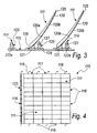
- the base 115 is designed to support a plurality of parabolic mirrors 111 and corresponding receiving elements 114 which are mutually connected by means of conductors 116.
- the parabolic mirrors 111 and the respective receiving elements 114 are arranged side by side so as to form parallel and adjacent rows 117 and laterally adjacent lines 118.
- Each receiving element 114 except for the ones arranged on the outer perimeter of the base 115, is arranged proximate to the back 120b of the next neighboring mirror 111, which lies above it.
- the radiation reflected toward the receiving element 114 is designated by the reference numeral 12a.
- the mirrors 111 are arranged advantageously in rows 117 and lines 118 so as to affect continuously, with respect to a direction which is perpendicular to the arrangement of the base 115, the area covered by the base 115 on which they are fitted; in this manner, the mirrors 111 catch all of the radiation that arrives on them at right angles to the base 115 and the surface for collecting the radiation 12 is maximized.
- the upper end edges 25 and 125 and the lower end edges 26 and 126 of a mirror 11 and 111 are cut along a direction which is parallel to the direction of the radiation 12.
- the receiving elements 14 and 114 can be sensors, transducers or photovoltaic cells and in general sensors which are sensitive to electromagnetic radiation.
- the receiving elements 14 and 114 can be sensors for detecting analog or digital signals.
- the receiving elements 14 and 114 must be positioned along the longitudinal central axis 119 of the corresponding mirror 111.
- Each mirror 11 and 111 is constituted by a parabolic body 20 and 120, the concave face 20a and 120a of which is coated with optical-grade reflective material.
- the parabolic body 20 and 120 is made of metallic material, plastic material, ceramic material or composite materials; depending on the electromagnetic band that must be captured by the device 10 and 110, the mirror is provided and coated with the material that is most suitable to obtain the best index of reflectance.
- the means for coupling the mirror 11 and 111 to the base 15 and 115 are provided by a lower portion 21 and 121 of the body 20 and 120 of the mirror, which is contoured so as to be inserted in a complementary shaped seat 22 and 122 provided on the base 15 and 115.
- the means for coupling the receiving element 14 and 114 to the base 15 and 115 are constituted by a support 23 and 123 for said receiving element; below the support 23 and 123 there is a portion 23a and 123a which is contoured so as to be inserted in a complementary shaped seat 24 and 124 provided on the base 15 and 115.
- the support 23 and 123 is made of a material which is capable of dissipating the excess heat from the supported receiving element 14 and 114.
- the lower portions 21, 23a, 121 and 123a respectively of the body 20 and 120 of the mirror and of the support 23 and 123 are substantially T-shaped and are adapted to be inserted in the corresponding seats 22, 24, 122 and 124, which are formed by complementarily shaped slots which can be accessed from one side of the base 15 and 115.
- the assembly of the device 110 according to the invention is very simple, quick and precise; the base 115 on which the slots for the lower portions 21, 23a, 121 and 123a are formed is in fact provided monolithically, and mounting the mirrors and receiving elements thereon requires only the insertion of said lower portions in the respective slots, without any other long and meticulous maneuvers for seeking the optimum mutual arrangement of the mirrors and the corresponding receiving elements.
- the support 23 and 123 for the receiving element 14 and 114 has a through hole 27 and 127 for the flow therein of coolant liquid for energy recovery of heat, if the device 10 and 110 according to the invention is used for example to provide a solar panel.
- the device 10 and 110 if used to provide solar or photovoltaic panels, comprises means, not shown for the sake of simplicity, for following automatically the source of the radiation 12 in order to vary the trim of said device, since the radiation 12 must reach the mirrors with a constant angle.
- the device 10 and 110 according to the invention can be assembled easily in a modular manner together with other identical devices to provide panels of any size according to requirements.
- a known type of these follower means can be for example a heliostat.
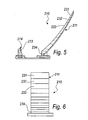
- the substantially parabolic mirror 211 is composed of a plurality of reflective elements arranged side by side, of which the figure illustrates by way of example the ones designated by the reference numerals 231, 232, 233 and 234.
- the mirror 211 can be provided with machinings, micromachinings and surface treatments such as to no longer have a single continuous reflective surface but a plurality of reflective elements which form a discontinuous reflective surface.
- the present invention provides a concentrating device which has a higher efficiency than known devices: the absence of lenses and in particular of Fresnel lenses in fact improves transmittance and eliminates the problem of chromatic aberration which is typical of lenses.
- the present invention provides a concentrating device in which thermal accumulation can be dissipated more efficiently than in known types of device, by virtue of the through hole on the support for the receiving elements, inside which it is possible to circulate a transfer fluid for dissipating the accumulated heat.
- the present invention provides a concentrating device which can be assembled more rapidly and at least as accurately as known types of concentrating device.
- the present invention provides a radiation concentrating device which is particularly but not exclusively suitable to provide solar or photovoltaic panels.
- the present invention provides a radiation concentrating device which can be manufactured with known systems and technologies.
- the materials employed may be any according to requirements and to the state of the art.
Landscapes
- Engineering & Computer Science (AREA)
- Physics & Mathematics (AREA)
- Life Sciences & Earth Sciences (AREA)
- Sustainable Development (AREA)
- Sustainable Energy (AREA)
- Thermal Sciences (AREA)
- Chemical & Material Sciences (AREA)
- Combustion & Propulsion (AREA)
- Mechanical Engineering (AREA)
- General Engineering & Computer Science (AREA)
- General Physics & Mathematics (AREA)
- Optics & Photonics (AREA)
- Health & Medical Sciences (AREA)
- Toxicology (AREA)
- Optical Elements Other Than Lenses (AREA)
- Photovoltaic Devices (AREA)
- Investigating Or Analysing Materials By Optical Means (AREA)
- External Artificial Organs (AREA)
- Paper (AREA)
- Measurement Of Radiation (AREA)
- Aerials With Secondary Devices (AREA)
Applications Claiming Priority (2)
| Application Number | Priority Date | Filing Date | Title |
|---|---|---|---|
| IT000153A ITPD20060153A1 (it) | 2006-04-24 | 2006-04-24 | Dispositivo concentratore di radiazioni |
| PCT/EP2007/003547 WO2007121971A1 (en) | 2006-04-24 | 2007-04-23 | Radiation concentrating device |
Publications (2)
| Publication Number | Publication Date |
|---|---|
| EP2010830A1 EP2010830A1 (en) | 2009-01-07 |
| EP2010830B1 true EP2010830B1 (en) | 2011-04-06 |
Family
ID=38222768
Family Applications (1)
| Application Number | Title | Priority Date | Filing Date |
|---|---|---|---|
| EP07724477A Not-in-force EP2010830B1 (en) | 2006-04-24 | 2007-04-23 | Radiation concentrating device |
Country Status (8)
| Country | Link |
|---|---|
| US (1) | US20090126776A1 (it) |
| EP (1) | EP2010830B1 (it) |
| CN (1) | CN101432579A (it) |
| AT (1) | ATE504789T1 (it) |
| DE (1) | DE602007013736D1 (it) |
| ES (1) | ES2364476T3 (it) |
| IT (1) | ITPD20060153A1 (it) |
| WO (1) | WO2007121971A1 (it) |
Families Citing this family (7)
| Publication number | Priority date | Publication date | Assignee | Title |
|---|---|---|---|---|
| US8592673B2 (en) * | 2009-05-04 | 2013-11-26 | The Boeing Company | Enclosed, off-axis solar concentrator |
| WO2011044277A2 (en) | 2009-10-06 | 2011-04-14 | Brightleaf Technologies, Inc. | Non-parabolic solar concentration to an area of controlled flux density conversion system and method |
| GB2488113A (en) * | 2011-02-14 | 2012-08-22 | Geoffrey David Horn | Apparatus for increasing the output power of solar cells |
| US20120273023A1 (en) * | 2011-04-28 | 2012-11-01 | Ely Jonathan | Collapsible reflector for solar panel |
| DE102012011969B4 (de) * | 2012-03-19 | 2016-11-03 | K2 Systems Gmbh | Solarmodulhalter |
| CN105355691B (zh) * | 2015-11-28 | 2017-05-31 | 东莞市天利太阳能有限公司 | 一种太阳能发电装置 |
| KR102330217B1 (ko) * | 2021-08-11 | 2021-11-24 | (주)푸드포트 | 균일한 초점영역을 형성한 태양광 발전장치 |
Family Cites Families (8)
| Publication number | Priority date | Publication date | Assignee | Title |
|---|---|---|---|---|
| US4337758A (en) * | 1978-06-21 | 1982-07-06 | Meinel Aden B | Solar energy collector and converter |
| US4315500A (en) * | 1978-07-12 | 1982-02-16 | Gonder Warren W | Collection of solar energy |
| US4408595A (en) * | 1978-09-05 | 1983-10-11 | Broyles Howard F | Turret mounted solar concentrator with boom mounted secondary mirror or collector |
| US4771764A (en) * | 1984-04-06 | 1988-09-20 | Cluff C Brent | Water-borne azimuth-altitude tracking solar concentrators |
| US5344496A (en) * | 1992-11-16 | 1994-09-06 | General Dynamics Corporation, Space Systems Division | Lightweight solar concentrator cell array |
| DE10025212A1 (de) * | 2000-05-22 | 2001-11-29 | Andreas Noehrig | Konzentrierendes Solarenergiesystem |
| DE05752475T1 (de) * | 2004-06-24 | 2009-09-17 | Heliodynamics Ltd., Caxton | Sonnenenergiesammelsysteme |
| US20080251113A1 (en) * | 2007-04-12 | 2008-10-16 | Horne Stephen J | Single mirror solar concentrator with efficient electrical and thermal management |
-
2006
- 2006-04-24 IT IT000153A patent/ITPD20060153A1/it unknown
-
2007
- 2007-04-23 US US12/226,414 patent/US20090126776A1/en not_active Abandoned
- 2007-04-23 WO PCT/EP2007/003547 patent/WO2007121971A1/en not_active Ceased
- 2007-04-23 DE DE602007013736T patent/DE602007013736D1/de active Active
- 2007-04-23 CN CNA2007800149334A patent/CN101432579A/zh active Pending
- 2007-04-23 AT AT07724477T patent/ATE504789T1/de not_active IP Right Cessation
- 2007-04-23 ES ES07724477T patent/ES2364476T3/es active Active
- 2007-04-23 EP EP07724477A patent/EP2010830B1/en not_active Not-in-force
Also Published As
| Publication number | Publication date |
|---|---|
| ATE504789T1 (de) | 2011-04-15 |
| EP2010830A1 (en) | 2009-01-07 |
| DE602007013736D1 (de) | 2011-05-19 |
| ITPD20060153A1 (it) | 2007-10-25 |
| CN101432579A (zh) | 2009-05-13 |
| WO2007121971A1 (en) | 2007-11-01 |
| ES2364476T3 (es) | 2011-09-05 |
| US20090126776A1 (en) | 2009-05-21 |
Similar Documents
| Publication | Publication Date | Title |
|---|---|---|
| EP2010830B1 (en) | Radiation concentrating device | |
| US7297865B2 (en) | Compact micro-concentrator for photovoltaic cells | |
| US20090000612A1 (en) | Apparatuses and methods for shaping reflective surfaces of optical concentrators | |
| EP2336671B9 (en) | Linear concentrating solar collector with decentered trough-type reflectors | |
| US20110061719A1 (en) | Solar electricity generation system | |
| US7607429B2 (en) | Multistage system for radiant energy flux transformation comprising an array of slat-like reflectors | |
| US20130247960A1 (en) | Solar-light concentration apparatus | |
| US9059352B2 (en) | Solar energy systems using external reflectors | |
| WO2007084518A2 (en) | A hybrid primary optical component for optical concentrators | |
| EP2489960A1 (en) | Solar-energy collector/concentrator, with cassegrain-type optics | |
| WO2011153633A1 (en) | Monolithic photovoltaic solar concentrator | |
| EP3149846B1 (en) | Solar concentrator | |
| EP2317242A2 (en) | Solid linear solar concentrator optical system with micro-faceted mirror array | |
| US20030137754A1 (en) | Multistage system for radiant energy flux transformation | |
| AU2018422303B2 (en) | Double-sided light-concentrating solar apparatus and system | |
| AU2007100370A4 (en) | Electricity generation device using solar power | |
| US20140102510A1 (en) | Concentrating solar energy collector | |
| US6061181A (en) | Nontracking light converger | |
| WO2006121686A2 (en) | Reflecting photonic concentrator | |
| EP3323198B1 (en) | Optical light-transmission element for a solar energy assembly comprising a harvesting portion and an alignment control portion, and method for alignment of such | |
| JPH0629883B2 (ja) | 太陽光発電装置 | |
| KR20130085132A (ko) | 태양광 발전용 프레넬 렌즈 - 광가이드 복합형 집광 렌즈 장치 | |
| CN101203717A (zh) | 收集器和用于获得来自太阳射线热量的收集器结构 | |
| EP0020153B1 (en) | Radiation collector | |
| US20130098427A1 (en) | Paraboloid reflectors |
Legal Events
| Date | Code | Title | Description |
|---|---|---|---|
| PUAI | Public reference made under article 153(3) epc to a published international application that has entered the european phase |
Free format text: ORIGINAL CODE: 0009012 |
|
| 17P | Request for examination filed |
Effective date: 20081015 |
|
| AK | Designated contracting states |
Kind code of ref document: A1 Designated state(s): AT BE BG CH CY CZ DE DK EE ES FI FR GB GR HU IE IS IT LI LT LU LV MC MT NL PL PT RO SE SI SK TR |
|
| AX | Request for extension of the european patent |
Extension state: AL BA HR MK RS |
|
| 17Q | First examination report despatched |
Effective date: 20090326 |
|
| GRAP | Despatch of communication of intention to grant a patent |
Free format text: ORIGINAL CODE: EPIDOSNIGR1 |
|
| DAX | Request for extension of the european patent (deleted) | ||
| GRAS | Grant fee paid |
Free format text: ORIGINAL CODE: EPIDOSNIGR3 |
|
| GRAA | (expected) grant |
Free format text: ORIGINAL CODE: 0009210 |
|
| AK | Designated contracting states |
Kind code of ref document: B1 Designated state(s): AT BE BG CH CY CZ DE DK EE ES FI FR GB GR HU IE IS IT LI LT LU LV MC MT NL PL PT RO SE SI SK TR |
|
| REG | Reference to a national code |
Ref country code: GB Ref legal event code: FG4D |
|
| REG | Reference to a national code |
Ref country code: CH Ref legal event code: EP |
|
| REG | Reference to a national code |
Ref country code: IE Ref legal event code: FG4D |
|
| REF | Corresponds to: |
Ref document number: 602007013736 Country of ref document: DE Date of ref document: 20110519 Kind code of ref document: P |
|
| REG | Reference to a national code |
Ref country code: DE Ref legal event code: R096 Ref document number: 602007013736 Country of ref document: DE Effective date: 20110519 |
|
| REG | Reference to a national code |
Ref country code: NL Ref legal event code: VDEP Effective date: 20110406 |
|
| REG | Reference to a national code |
Ref country code: GR Ref legal event code: EP Ref document number: 20110401287 Country of ref document: GR Effective date: 20110714 |
|
| PG25 | Lapsed in a contracting state [announced via postgrant information from national office to epo] |
Ref country code: SI Free format text: LAPSE BECAUSE OF FAILURE TO SUBMIT A TRANSLATION OF THE DESCRIPTION OR TO PAY THE FEE WITHIN THE PRESCRIBED TIME-LIMIT Effective date: 20110406 |
|
| REG | Reference to a national code |
Ref country code: ES Ref legal event code: FG2A Ref document number: 2364476 Country of ref document: ES Kind code of ref document: T3 Effective date: 20110905 |
|
| LTIE | Lt: invalidation of european patent or patent extension |
Effective date: 20110406 |
|
| PG25 | Lapsed in a contracting state [announced via postgrant information from national office to epo] |
Ref country code: LT Free format text: LAPSE BECAUSE OF FAILURE TO SUBMIT A TRANSLATION OF THE DESCRIPTION OR TO PAY THE FEE WITHIN THE PRESCRIBED TIME-LIMIT Effective date: 20110406 Ref country code: PT Free format text: LAPSE BECAUSE OF FAILURE TO SUBMIT A TRANSLATION OF THE DESCRIPTION OR TO PAY THE FEE WITHIN THE PRESCRIBED TIME-LIMIT Effective date: 20110808 Ref country code: SE Free format text: LAPSE BECAUSE OF FAILURE TO SUBMIT A TRANSLATION OF THE DESCRIPTION OR TO PAY THE FEE WITHIN THE PRESCRIBED TIME-LIMIT Effective date: 20110406 |
|
| PG25 | Lapsed in a contracting state [announced via postgrant information from national office to epo] |
Ref country code: IS Free format text: LAPSE BECAUSE OF FAILURE TO SUBMIT A TRANSLATION OF THE DESCRIPTION OR TO PAY THE FEE WITHIN THE PRESCRIBED TIME-LIMIT Effective date: 20110806 Ref country code: AT Free format text: LAPSE BECAUSE OF FAILURE TO SUBMIT A TRANSLATION OF THE DESCRIPTION OR TO PAY THE FEE WITHIN THE PRESCRIBED TIME-LIMIT Effective date: 20110406 Ref country code: MC Free format text: LAPSE BECAUSE OF NON-PAYMENT OF DUE FEES Effective date: 20110430 Ref country code: BE Free format text: LAPSE BECAUSE OF FAILURE TO SUBMIT A TRANSLATION OF THE DESCRIPTION OR TO PAY THE FEE WITHIN THE PRESCRIBED TIME-LIMIT Effective date: 20110406 Ref country code: FI Free format text: LAPSE BECAUSE OF FAILURE TO SUBMIT A TRANSLATION OF THE DESCRIPTION OR TO PAY THE FEE WITHIN THE PRESCRIBED TIME-LIMIT Effective date: 20110406 Ref country code: CY Free format text: LAPSE BECAUSE OF FAILURE TO SUBMIT A TRANSLATION OF THE DESCRIPTION OR TO PAY THE FEE WITHIN THE PRESCRIBED TIME-LIMIT Effective date: 20110406 Ref country code: LV Free format text: LAPSE BECAUSE OF FAILURE TO SUBMIT A TRANSLATION OF THE DESCRIPTION OR TO PAY THE FEE WITHIN THE PRESCRIBED TIME-LIMIT Effective date: 20110406 |
|
| REG | Reference to a national code |
Ref country code: CH Ref legal event code: PL |
|
| PG25 | Lapsed in a contracting state [announced via postgrant information from national office to epo] |
Ref country code: NL Free format text: LAPSE BECAUSE OF FAILURE TO SUBMIT A TRANSLATION OF THE DESCRIPTION OR TO PAY THE FEE WITHIN THE PRESCRIBED TIME-LIMIT Effective date: 20110406 |
|
| PGFP | Annual fee paid to national office [announced via postgrant information from national office to epo] |
Ref country code: MT Payment date: 20110429 Year of fee payment: 5 |
|
| PG25 | Lapsed in a contracting state [announced via postgrant information from national office to epo] |
Ref country code: CH Free format text: LAPSE BECAUSE OF NON-PAYMENT OF DUE FEES Effective date: 20110430 Ref country code: EE Free format text: LAPSE BECAUSE OF FAILURE TO SUBMIT A TRANSLATION OF THE DESCRIPTION OR TO PAY THE FEE WITHIN THE PRESCRIBED TIME-LIMIT Effective date: 20110406 Ref country code: CZ Free format text: LAPSE BECAUSE OF FAILURE TO SUBMIT A TRANSLATION OF THE DESCRIPTION OR TO PAY THE FEE WITHIN THE PRESCRIBED TIME-LIMIT Effective date: 20110406 Ref country code: LI Free format text: LAPSE BECAUSE OF NON-PAYMENT OF DUE FEES Effective date: 20110430 |
|
| REG | Reference to a national code |
Ref country code: IE Ref legal event code: MM4A |
|
| PLBE | No opposition filed within time limit |
Free format text: ORIGINAL CODE: 0009261 |
|
| STAA | Information on the status of an ep patent application or granted ep patent |
Free format text: STATUS: NO OPPOSITION FILED WITHIN TIME LIMIT |
|
| PG25 | Lapsed in a contracting state [announced via postgrant information from national office to epo] |
Ref country code: RO Free format text: LAPSE BECAUSE OF FAILURE TO SUBMIT A TRANSLATION OF THE DESCRIPTION OR TO PAY THE FEE WITHIN THE PRESCRIBED TIME-LIMIT Effective date: 20110406 Ref country code: SK Free format text: LAPSE BECAUSE OF FAILURE TO SUBMIT A TRANSLATION OF THE DESCRIPTION OR TO PAY THE FEE WITHIN THE PRESCRIBED TIME-LIMIT Effective date: 20110406 Ref country code: PL Free format text: LAPSE BECAUSE OF FAILURE TO SUBMIT A TRANSLATION OF THE DESCRIPTION OR TO PAY THE FEE WITHIN THE PRESCRIBED TIME-LIMIT Effective date: 20110406 Ref country code: DK Free format text: LAPSE BECAUSE OF FAILURE TO SUBMIT A TRANSLATION OF THE DESCRIPTION OR TO PAY THE FEE WITHIN THE PRESCRIBED TIME-LIMIT Effective date: 20110406 |
|
| 26N | No opposition filed |
Effective date: 20120110 |
|
| GBPC | Gb: european patent ceased through non-payment of renewal fee |
Effective date: 20110706 |
|
| PG25 | Lapsed in a contracting state [announced via postgrant information from national office to epo] |
Ref country code: IE Free format text: LAPSE BECAUSE OF NON-PAYMENT OF DUE FEES Effective date: 20110423 |
|
| REG | Reference to a national code |
Ref country code: DE Ref legal event code: R097 Ref document number: 602007013736 Country of ref document: DE Effective date: 20120110 |
|
| PG25 | Lapsed in a contracting state [announced via postgrant information from national office to epo] |
Ref country code: GB Free format text: LAPSE BECAUSE OF NON-PAYMENT OF DUE FEES Effective date: 20110706 |
|
| PG25 | Lapsed in a contracting state [announced via postgrant information from national office to epo] |
Ref country code: LU Free format text: LAPSE BECAUSE OF NON-PAYMENT OF DUE FEES Effective date: 20110423 |
|
| PG25 | Lapsed in a contracting state [announced via postgrant information from national office to epo] |
Ref country code: BG Free format text: LAPSE BECAUSE OF FAILURE TO SUBMIT A TRANSLATION OF THE DESCRIPTION OR TO PAY THE FEE WITHIN THE PRESCRIBED TIME-LIMIT Effective date: 20110706 |
|
| PG25 | Lapsed in a contracting state [announced via postgrant information from national office to epo] |
Ref country code: MT Free format text: LAPSE BECAUSE OF NON-PAYMENT OF DUE FEES Effective date: 20130430 |
|
| PG25 | Lapsed in a contracting state [announced via postgrant information from national office to epo] |
Ref country code: TR Free format text: LAPSE BECAUSE OF FAILURE TO SUBMIT A TRANSLATION OF THE DESCRIPTION OR TO PAY THE FEE WITHIN THE PRESCRIBED TIME-LIMIT Effective date: 20110406 |
|
| PG25 | Lapsed in a contracting state [announced via postgrant information from national office to epo] |
Ref country code: HU Free format text: LAPSE BECAUSE OF FAILURE TO SUBMIT A TRANSLATION OF THE DESCRIPTION OR TO PAY THE FEE WITHIN THE PRESCRIBED TIME-LIMIT Effective date: 20110406 |
|
| PGFP | Annual fee paid to national office [announced via postgrant information from national office to epo] |
Ref country code: GR Payment date: 20140327 Year of fee payment: 8 |
|
| PGFP | Annual fee paid to national office [announced via postgrant information from national office to epo] |
Ref country code: ES Payment date: 20140529 Year of fee payment: 8 Ref country code: DE Payment date: 20140430 Year of fee payment: 8 Ref country code: FR Payment date: 20140331 Year of fee payment: 8 |
|
| PG25 | Lapsed in a contracting state [announced via postgrant information from national office to epo] |
Ref country code: MT Free format text: LAPSE BECAUSE OF NON-PAYMENT OF DUE FEES Effective date: 20120430 |
|
| REG | Reference to a national code |
Ref country code: DE Ref legal event code: R082 Ref document number: 602007013736 Country of ref document: DE Representative=s name: GRAMM, LINS & PARTNER PATENT- UND RECHTSANWAEL, DE |
|
| PGFP | Annual fee paid to national office [announced via postgrant information from national office to epo] |
Ref country code: IT Payment date: 20150327 Year of fee payment: 9 |
|
| REG | Reference to a national code |
Ref country code: DE Ref legal event code: R119 Ref document number: 602007013736 Country of ref document: DE |
|
| PG25 | Lapsed in a contracting state [announced via postgrant information from national office to epo] |
Ref country code: DE Free format text: LAPSE BECAUSE OF NON-PAYMENT OF DUE FEES Effective date: 20151103 Ref country code: GR Free format text: LAPSE BECAUSE OF NON-PAYMENT OF DUE FEES Effective date: 20151106 |
|
| REG | Reference to a national code |
Ref country code: FR Ref legal event code: ST Effective date: 20151231 |
|
| REG | Reference to a national code |
Ref country code: GR Ref legal event code: ML Ref document number: 20110401287 Country of ref document: GR Effective date: 20151106 |
|
| PG25 | Lapsed in a contracting state [announced via postgrant information from national office to epo] |
Ref country code: FR Free format text: LAPSE BECAUSE OF NON-PAYMENT OF DUE FEES Effective date: 20150430 |
|
| REG | Reference to a national code |
Ref country code: ES Ref legal event code: FD2A Effective date: 20161130 |
|
| PG25 | Lapsed in a contracting state [announced via postgrant information from national office to epo] |
Ref country code: IT Free format text: LAPSE BECAUSE OF NON-PAYMENT OF DUE FEES Effective date: 20160423 Ref country code: ES Free format text: LAPSE BECAUSE OF NON-PAYMENT OF DUE FEES Effective date: 20150424 |
|
| PG25 | Lapsed in a contracting state [announced via postgrant information from national office to epo] |
Ref country code: MT Free format text: LAPSE BECAUSE OF NON-PAYMENT OF DUE FEES Effective date: 20120423 |