EP2010718B1 - Method of installing bucket foundation structure - Google Patents
Method of installing bucket foundation structure Download PDFInfo
- Publication number
- EP2010718B1 EP2010718B1 EP07722557.1A EP07722557A EP2010718B1 EP 2010718 B1 EP2010718 B1 EP 2010718B1 EP 07722557 A EP07722557 A EP 07722557A EP 2010718 B1 EP2010718 B1 EP 2010718B1
- Authority
- EP
- European Patent Office
- Prior art keywords
- bucket
- foundation structure
- stage
- bucket foundation
- chambers
- Prior art date
- Legal status (The legal status is an assumption and is not a legal conclusion. Google has not performed a legal analysis and makes no representation as to the accuracy of the status listed.)
- Active
Links
Images


Classifications
-
- E—FIXED CONSTRUCTIONS
- E02—HYDRAULIC ENGINEERING; FOUNDATIONS; SOIL SHIFTING
- E02B—HYDRAULIC ENGINEERING
- E02B17/00—Artificial islands mounted on piles or like supports, e.g. platforms on raisable legs or offshore constructions; Construction methods therefor
- E02B17/02—Artificial islands mounted on piles or like supports, e.g. platforms on raisable legs or offshore constructions; Construction methods therefor placed by lowering the supporting construction to the bottom, e.g. with subsequent fixing thereto
-
- E—FIXED CONSTRUCTIONS
- E02—HYDRAULIC ENGINEERING; FOUNDATIONS; SOIL SHIFTING
- E02D—FOUNDATIONS; EXCAVATIONS; EMBANKMENTS; UNDERGROUND OR UNDERWATER STRUCTURES
- E02D27/00—Foundations as substructures
- E02D27/32—Foundations for special purposes
- E02D27/52—Submerged foundations, i.e. submerged in open water
-
- E—FIXED CONSTRUCTIONS
- E02—HYDRAULIC ENGINEERING; FOUNDATIONS; SOIL SHIFTING
- E02B—HYDRAULIC ENGINEERING
- E02B17/00—Artificial islands mounted on piles or like supports, e.g. platforms on raisable legs or offshore constructions; Construction methods therefor
-
- E—FIXED CONSTRUCTIONS
- E02—HYDRAULIC ENGINEERING; FOUNDATIONS; SOIL SHIFTING
- E02B—HYDRAULIC ENGINEERING
- E02B17/00—Artificial islands mounted on piles or like supports, e.g. platforms on raisable legs or offshore constructions; Construction methods therefor
- E02B2017/0056—Platforms with supporting legs
- E02B2017/0073—Details of sea bottom engaging footing
- E02B2017/0078—Suction piles, suction cans
Definitions
- the invention is related to WO 01/71105 A1 : "Method for establishing a foundation in a seabed for an offshore facility and the foundation according to the method”.
- the method of the new invention is to install a foundation structure (1), see fig. 1 , consisting of one, two, three or more skirts, into soils (5) of varying characteristics in a controlled manner ( fig. 1 ).
- the method finds use either in a seabed or an onshore location where the soil is beneath ground water level.
- the skirt can be constructed of sheet metal, concrete or composite material forming an enclosed structure of any open-ended shape used for e.g. bucket foundation, monopiles, suction anchors or soil stabilisation constructions.
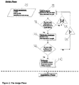
- the method is based on a design phase ( fig. 2 ) and an installation phase ( fig. 3 ) which is the basis for controlling the suction pressure in the enclosure and the pressures and flows along the lower perimeter/rim (edge) (4) of the skirt while penetrating the foundation structure into the soil (5).
- the invention makes it possible to control penetration e.g. suction anchors or bucket foundations into the seabed soil even if the soil consists of impermeable layers where it is not possible to establish a flow of water (seepage) around the rim by means of under pressure in the interior of the structure.
- the main structure is designed to absorb the different forces and loads which is applied during the installation process and during the operation of the facility, that is to say all the forces and loads the structure is intended and designed to withstand during the operational lifetime of the said facility.
- An attachment along the rim of the skirt consists of one or more chambers, typically four, with nozzles where pressure and/or flows of a media, e.g. fluid, air/gas or steam, can be established in a controlled manner through said chambers and nozzles, resulting in the reduction of the shear strength in the soil in the near surroundings of the rim and/or skirt.
- the pressures and flows can be controlled by means of valves or positive displacements pumps (3) for one, more or all chambers during the placement, i.e. while the structure is lowered into the soil.
- the invention ensures that the penetration speed and the inclination of the construction are controlled within the design requirements.
- the chamber(s) at the rim (4) can be established in the form of a pipe work fitted along the rim with drilled or fitted nozzles pointed in the desired direction(s).
- the pipe work is connected through risers to a central manifold supplied with the media at a sufficient flow and pressure.
- Each riser section is fitted with a controlling device (3) regulation flow and pressure.
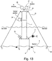
- the main structure can be fitted with a system comprising three or more electrically and/or hydraulically operated winches (34) which are connected to preinstalled anchors (36) by wires (35).
- the three winches connected to separate anchors are used, they are arranged with approximately 120° between them, such that they radially extend into different directions.
- This system can be used as redundant or excess control measure of the inclination in case of extreme environmental parameters such as high waves or if the rim pressure system is not available for any reason.
- the operation of the winches can introduce a horizontal force in the opposite direction of an inclination as a corrective action.
- the main structure is fitted with transducers for monitoring and logging purposes: The pressure inside the enclosure (23), the vertical position (24) and the inclinations (26) and (27).
- the transducers are connected to a central control system (15).
- the pipe work on the rim can be of greater, equal or less dimensions than the thickness of the rim.
- an under pressure may be created in the inside of the bucket structure. This may be established by activating an evacuation pump creating suction i.e. a lower pressure inside the bucket structure than outside the structure.
- the method consists of two stages:
- the method is an integrated approach with regards to the design of the said foundation structures and is based on the calculation and simulation of the precise position of each individual foundation structure with respect to physical in-situ parameters as foundation position and soil characteristics at the particular installation location.
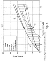
- the prediction (14) represented by a diagram, ( fig. 4 ), showing the calculation of the needed penetration forces (31), the available suction pressure (32) and the maximum allowable suction pressure not causing ground or material failure (33) in accordance to the design code in question.
- CPT cone penetration test
- the input data are evaluated and transformed into the design parameters (7), called the design basis.
- the load analysis (8) is an analytical and/or numerical analysis which determines the physical size of the bucket, diameter and skirt length, based on a design methodology using a combination of earth pressure on the skirt and the vertical bearing capacity of the bucket.
- the bucket foundation is regarded as two cramp walls where it is possible to develop stabilizing earth pressures on the front and back side of the foundation
- an analytical model for the design of a bucket foundation with the diameter D and a skirt depth of d can be used.
- the earth pressure action on the bucket is assumed to rotate as a solid body around a point of rotation O found in the depth d r , below the soil surface.
- the mechanism of the earth pressure and reaction of the bearing capacity for the point of rotation is either anticipated to be placed below the foundation level ( fig. 6a ), or anticipated to be placed above the foundation level ( fig. 6b ).
- the bucket foundation is assumed built of two cramp walls where it is possible to develop a stabilizing earth pressure on the front and back side of the foundation the earth pressures can be calculated with the following approximation.
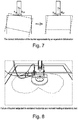
- the point of rotation is found in the plane of the wall, which in this case is not feasible.
- the deformation of the bucket is described by two parallel walls with a point of rotation corresponding with the fact that these points are found in the plane of the wall, ( fig. 7 ) shows the equivalent mode of rupture.
- K ⁇ pr K p pr + 0,007 e 9 ⁇ sin ⁇ ⁇ ⁇ 1
- K ⁇ ar K p ar ⁇ 0,007 1 ⁇ e ⁇ 9 ⁇ sin ⁇ ⁇
- K p pr 1 + sin ⁇ e ⁇ 2 + ⁇ tan ⁇ ⁇
- K p ar 1 ⁇ sin ⁇ e ⁇ ⁇ 2 ⁇ ⁇ tan ⁇ ⁇
- a bucket foundation exposed to a combined moment and horizontal load shows a distinct spatial rupture zones, ( fig. 8 ).
- Den spatially influence around the bucket can be interpreted as a active diameter D ⁇ D of the bucket on which the earth pressure may act from the plane state.
- the input data for the load analyses is the design parameters (7).
- the analysis process is performed using formulas and methods based on series of tests on scale buckets varying from ⁇ 100 mm to ⁇ 2000 mm in diameter.
- the ability of the structure/soil interaction to handle the load regime, e.g. static load and dynamic load, is evaluated. If the safety level stipulated in the design code in question, is not within the given limits, the diameter and /or the length of the bucket respective skirt are increased (10), and the load analyses is repeated.
- the penetration analysis (11) is performed with the calculated bucket size.
- the calculation follows the design procedure of a traditional, embedded gravity foundation.
- the gravity weight of the foundation is primarily obtained from the soil volume enclosed by the pile, yielding also an effective foundation depth at the skirt tip level.
- the moment capacity of the foundation is obtained by a traditional, eccentric bearing pressure combined with the development of resisting earth pressures along the height of the skirt.
- the design may be carried out using a design model that combines the well-known bearing capacity formula with equally well-known earth pressure theories.
- the foundation is designed so that the point of rotation is above the foundation level, i.e. in the soil surrounded by the skirt and the bearing capacity. Rupture occurs as a line failure developed under the foundation.
- the prediction is presented in a graphic diagram, ( fig.4 ), to be used by the detailed design for the construction of the foundation structure and for the installation process.
- the prediction is presented as an operation guideline used by the operators or is feed directly to a computerized control system as data input.
- the prediction includes parameters for the penetration force, the critical suction pressure which will cause soil failure, critical suction pressure which will cause buckling of the foundation structure, and for available suction pressure due to limitations in the pump system as a function of the penetration depth.
- the parameters (14) predicted in the first stage are according to claim 1.
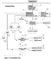
- the installation of the said foundation structures is a controlled operation of the penetration process.
- the operation of the control system (15) is performed either manually, semi automatically or fully automatically based upon interpretation of the above-mentioned data (14).
- the control is performed based on readings of the actual penetration depth and inclination of the structure by high accuracy instruments.
- control action can be introduced in different modes:
- the mode is selected in accordance with the prediction, depending of the properties of the soil e.g. grain size, grain distribution, permeability.
- the soils reaction to the initiated control actions is either reduction of the shear strengths at the rim of the skirt (30) or reduction of the skin friction on the skirt surface or a combination of both.
- the control system consists of elements illustrated in the flow diagram ( fig. 3 ) and example of the user interface regarding actual readings ( fig. 12 ).
- Input elements are the measuring devices for the vertical position (24), the inclination in X-direction (26), the inclination in Y-direction (27) and the pressure inside the bucket, e.g. suction pressure (23).
- Output elements are data to regulate the suction pressure (16), data to regulate the individual pressure/flow (17) in one or more chambers at the skirt rim (4) and data for the event recording (18) for the verification of the installation process.
- An optional output element is data to operate the optional winches (34), see fig. 13 .
- the alternative or additional system comprising winches is explained above.
- control routines are implemented in the control system to initiate the actions ensuring the installation process to be within the predicted tolerances.
- three routines are needed, 1) verification of vertical position (19), 2) verification of penetration velocity/suction pressure (20) and 3) verification of inclination (25).
- the sequence of the control routines can be arranged to suit the actual installations situation. According to the invention, the comparison is made for the penetration force (14), for the required suction (14) and for the critical suction pressures (14) derived in the first stage.
- the routine for vertical position (19) measures the vertical position (24) of the structure with reference to the seabed, if the position is within the tolerances of the finial level; say +/- 200 mm, the installation procedure is finalized.
- the routine for verification of penetration velocity/suction pressure (20) measures the vertical position (24) with a sampling rate sufficient to calculate the penetration velocity.
- the installation process is started in a mode with no pressure/flow in the chambers at the rim (4). If the rate of penetration is below the minimum level, say ⁇ 0,5 m/h, the suction pressure is increased (22). The suction pressure is measured (23); the suction pressure must be kept below the safety level for soil failure, say 60% of the critical suction pressure calculated in the prediction. If the suction pressure is at the maximum level and the penetration velocity is not increased, the control mode is changed (21) to constant or pulsating pressure/flow in the entire chambers (4).
- the verification of inclination (25) measures the inclination in the X- direction (26) and the Y-direction. If the inclination is not within the tolerances stated in the design basis, corrective action is initiated (28). If running in the control mode with no pressure/flow in the chambers (4), the control device (3) in the sector of the same direction as the desired correction is activated. If running in the control mode with constant/pulsation pressure/flow in the chambers (4), the control device (3) in the opposite sector of the direction as the desired correction is deactivated. An optional control measure can be initiated by operating the winch system (34).
- the bucket foundation can be used for e.g. offshore based wind farms where the wind turbines or metrology masts are mounted on a foundation structure provided in the seabed.
- the application of the bucket foundation can be facilitated in a variety of site locations and load regimes in the range as follows: Seabed soils: Loose to very dense sand and/or soft to very stiff clays Water depth: 0 - 50 m
- Load regime Vertical loads: 500 - 20.000 kN
- Horizontal loads 100 - 2.000 kN
- Overturning moment 10.000 - 600.000 kNm
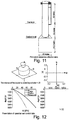
- FIG. 11 An example of a typical bucket foundation for offshore wind turbine installation is shown in ( fig. 11 ).
- the overturning moment at seabed level is 160.000 kNm
- vertical load is 4.500 kN
- horizontal load is 1000 kN.
- the seabed consists of medium dense sand and medium stiff clay.
- the foundation structure consists of a bucket with a diameter of 11 m and a skirt length of 11,5 m and a total height over seabed of 28 m.
- the overall tonnage of the foundation structure is approximately 270 tons.
- the thickness of the steel sheet material is 15 - 60 mm in the various part of the structure.
- the skirt is penetrated into the seabed with a velocity of 1-2 m/h giving an overall installation time for the foundation of 18 -24 hours exclusive of work for scour protection if needed.
Landscapes
- Engineering & Computer Science (AREA)
- General Engineering & Computer Science (AREA)
- Structural Engineering (AREA)
- Civil Engineering (AREA)
- General Life Sciences & Earth Sciences (AREA)
- Life Sciences & Earth Sciences (AREA)
- Mechanical Engineering (AREA)
- Mining & Mineral Resources (AREA)
- Paleontology (AREA)
- Earth Drilling (AREA)
- Foundations (AREA)
- Operation Control Of Excavators (AREA)
- Investigating Strength Of Materials By Application Of Mechanical Stress (AREA)
- Consolidation Of Soil By Introduction Of Solidifying Substances Into Soil (AREA)
Priority Applications (1)
| Application Number | Priority Date | Filing Date | Title |
|---|---|---|---|
| PL07722557T PL2010718T3 (pl) | 2006-04-10 | 2007-04-10 | Sposób montażu kubełkowej konstrukcji fundamentowej |
Applications Claiming Priority (2)
| Application Number | Priority Date | Filing Date | Title |
|---|---|---|---|
| DKPA200600520 | 2006-04-10 | ||
| PCT/DK2007/000178 WO2007115573A1 (en) | 2006-04-10 | 2007-04-10 | Foundation structure |
Publications (2)
| Publication Number | Publication Date |
|---|---|
| EP2010718A1 EP2010718A1 (en) | 2009-01-07 |
| EP2010718B1 true EP2010718B1 (en) | 2019-08-07 |
Family
ID=38328216
Family Applications (1)
| Application Number | Title | Priority Date | Filing Date |
|---|---|---|---|
| EP07722557.1A Active EP2010718B1 (en) | 2006-04-10 | 2007-04-10 | Method of installing bucket foundation structure |
Country Status (11)
| Country | Link |
|---|---|
| US (2) | US7891910B2 (pl) |
| EP (1) | EP2010718B1 (pl) |
| KR (1) | KR101435219B1 (pl) |
| CN (1) | CN101466900A (pl) |
| AU (1) | AU2007236402B2 (pl) |
| BR (1) | BRPI0710056B1 (pl) |
| CA (1) | CA2648859C (pl) |
| DK (1) | DK2010718T3 (pl) |
| LT (1) | LT2010718T (pl) |
| PL (1) | PL2010718T3 (pl) |
| WO (1) | WO2007115573A1 (pl) |
Families Citing this family (26)
| Publication number | Priority date | Publication date | Assignee | Title |
|---|---|---|---|---|
| PL2010718T3 (pl) * | 2006-04-10 | 2020-03-31 | Mbd Offshore Power A/S | Sposób montażu kubełkowej konstrukcji fundamentowej |
| US8613569B2 (en) | 2008-11-19 | 2013-12-24 | Efficient Engineering, Llc | Stationary positioned offshore windpower plant (OWP) and the methods and means for its assembling, transportation, installation and servicing |
| CN102561286A (zh) * | 2010-12-20 | 2012-07-11 | 三一电气有限责任公司 | 负压式沉贯控制系统 |
| CN102360087B (zh) * | 2011-09-08 | 2013-04-24 | 山东科技大学 | 一种用于模拟采动煤层底板突水的试验系统及其方法 |
| DK177372B1 (en) * | 2012-02-10 | 2013-02-25 | Universal Foundation As | Method of installing a foundation in the sea bed and such foundation |
| US8684629B2 (en) | 2012-07-10 | 2014-04-01 | Kyle D. Asplund | Sea floor anchoring apparatus |
| WO2015028020A1 (en) | 2013-08-28 | 2015-03-05 | Mhi Vestas Offshore Wind A/S | Method of installing a foundation for an offshore wind turbine and a template for use herein |
| CN103669382A (zh) * | 2013-12-19 | 2014-03-26 | 天津港(集团)有限公司 | 箱筒型基础结构的下沉入地基土中的安装调平稳固方法 |
| CN105809610A (zh) * | 2014-12-30 | 2016-07-27 | 上海浦东建筑设计研究院有限公司 | 一种基坑支撑拆除对周边地层影响的评估方法 |
| NO342444B1 (no) * | 2015-11-25 | 2018-05-22 | Neodrill As | System for fundamentering av brønnhoder |
| CN106055801B (zh) * | 2016-06-03 | 2018-12-14 | 武汉科技大学 | 一种深基坑支撑梁爆破拆除顺序的确定方法 |
| US11668065B2 (en) | 2016-12-15 | 2023-06-06 | Ventower Industries | Method and apparatus for manufacturing marine foundation |
| EP3561181A1 (en) * | 2018-04-23 | 2019-10-30 | Ørsted Wind Power A/S | Foundation for a structure |
| DE102019104292A1 (de) * | 2019-02-20 | 2020-08-20 | Innogy Se | Einvibrieren von Gründungen |
| CN109944268A (zh) * | 2019-04-19 | 2019-06-28 | 中交第一航务工程勘察设计院有限公司 | 用于地质勘探平台中带隔水膜的筒型基础结构 |
| EP3910113A1 (en) * | 2020-05-13 | 2021-11-17 | Ørsted Wind Power A/S | A method of installing a foundation and a foundation for a structure |
| WO2022123288A1 (en) * | 2020-12-08 | 2022-06-16 | Neodrill As | Suction anchor or well support foundation for use in permeable water bottom formations |
| US12522324B2 (en) * | 2021-05-07 | 2026-01-13 | Stationkeep Llc | Foot pad for submerged machinery |
| EP4089235B1 (en) * | 2021-05-11 | 2025-07-09 | Ørsted Wind Power A/S | A method of installing a foundation and a foundation for a structure |
| GB2611090A (en) * | 2021-09-27 | 2023-03-29 | Equinor Energy As | Method of installing or remediating suction bucket structures for wind turbines |
| GB2613802B (en) * | 2021-12-14 | 2024-09-18 | Subsea 7 Norway As | Installation and removal of subsea foundations |
| CN116623720B (zh) * | 2022-02-11 | 2024-10-29 | 上海勘测设计研究院有限公司 | 一种海上风电桩基的自维护防冲刷装置 |
| CN114635456A (zh) * | 2022-04-24 | 2022-06-17 | 江苏道达风电设备科技有限公司 | 一种基于现场的复合筒型基础抗倾覆模型及其试验方法 |
| CN114840939A (zh) * | 2022-05-06 | 2022-08-02 | 中国华能集团清洁能源技术研究院有限公司 | 一种吸力式桩-桶复合基础设计优化及安装方法 |
| JP2024041545A (ja) * | 2022-09-14 | 2024-03-27 | 東洋建設株式会社 | サクションバケット基礎工法及び施工管理システム |
| CN115492154B (zh) * | 2022-09-21 | 2024-06-21 | 山东大学 | 一种可实现自稳定的装配式桶形基础配件及应用方法 |
Family Cites Families (25)
| Publication number | Priority date | Publication date | Assignee | Title |
|---|---|---|---|---|
| US4036161A (en) * | 1973-07-04 | 1977-07-19 | The Secretary Of State For Industry In Her Britannic Majesty's Government Of The United Kingdom Of Great Britain & Northern Ireland | Underwater anchoring apparatus |
| US4109477A (en) * | 1974-02-18 | 1978-08-29 | Salzgitter Maschinen Ag | Offshore driller rig |
| US3965687A (en) * | 1974-08-15 | 1976-06-29 | J. Ray Mcdermott & Co., Inc. | Apparatus for anchoring a structure to the floor of a body of water |
| GB1503208A (en) * | 1975-06-11 | 1978-03-08 | Hansen F | Offshore marine structures and methods for the construction thereof |
| US4069681A (en) * | 1976-02-02 | 1978-01-24 | Texaco Inc. | Offshore structure for deltaic substrates |
| US4106302A (en) * | 1976-05-17 | 1978-08-15 | Maschinenfabrik Augsburg-Nurnberg Aktiengesellschaft | Off-shore drilling and production platform and method of building same |
| US4558744A (en) * | 1982-09-14 | 1985-12-17 | Canocean Resources Ltd. | Subsea caisson and method of installing same |
| US4575282A (en) * | 1984-06-04 | 1986-03-11 | Pardue Sr James H | System for driving open end pipe piles on the ocean floor using pneumatic evacuation and existing hydrostatic pressure |
| US4830541A (en) * | 1986-05-30 | 1989-05-16 | Shell Offshore Inc. | Suction-type ocean-floor wellhead |
| US4721415A (en) * | 1986-06-06 | 1988-01-26 | Shell Offshore Inc. | Well base in ocean floor |
| US4761096A (en) * | 1987-02-24 | 1988-08-02 | Lin Sheng S | Universal footing with jetting system |
| NO176215B (no) | 1992-09-24 | 1994-11-14 | Norske Stats Oljeselskap | Anordning for fundamentering av en fagverkskonstruksjon eller undervannsinstallasjon til havs |
| GB9308905D0 (en) * | 1993-04-29 | 1993-06-16 | Erbrich Carl T | Foundation with installation skirt device |
| GB9805286D0 (en) | 1998-03-13 | 1998-05-06 | Resource Marginal Systems Ltd | Releasable footpads for reusable seabed structure |
| EP1068403B2 (en) * | 1998-04-02 | 2018-10-10 | SPT Equipment bv | Marine structure |
| US6481932B1 (en) * | 1999-11-18 | 2002-11-19 | Suction Pile Technology B.V. | Marine structure |
| US6203248B1 (en) * | 2000-02-03 | 2001-03-20 | Atwood Oceanics, Inc. | Sliding-resistant bottom-founded offshore structures |
| DK1268947T3 (da) | 2000-03-23 | 2008-05-13 | Bruno Schakenda | Havbundsfundament |
| JP4498571B2 (ja) | 2000-09-18 | 2010-07-07 | ヤマハ化工建設株式会社 | 底部拡大構造物の構築方法 |
| US7287935B1 (en) * | 2003-07-16 | 2007-10-30 | Gehring Donald H | Tendon assembly for mooring offshore structure |
| GB0324317D0 (en) * | 2003-10-17 | 2003-11-19 | Dixon Richard K | A composite marine foundation |
| DE102005014868A1 (de) * | 2005-03-30 | 2006-10-05 | Repower Systems Ag | Offshore-Windenergieanlage mit rutschfesten Füßen |
| JP2006322240A (ja) | 2005-05-19 | 2006-11-30 | Kouchi Marutaka:Kk | 土砂防壁構築方法及び土砂防壁 |
| US8011857B2 (en) * | 2005-09-13 | 2011-09-06 | Offshore Technology Development Pte Ltd | Extraction system for removable marine footing |
| PL2010718T3 (pl) * | 2006-04-10 | 2020-03-31 | Mbd Offshore Power A/S | Sposób montażu kubełkowej konstrukcji fundamentowej |
-
2007
- 2007-04-10 PL PL07722557T patent/PL2010718T3/pl unknown
- 2007-04-10 US US12/226,255 patent/US7891910B2/en active Active
- 2007-04-10 LT LT07722557T patent/LT2010718T/lt unknown
- 2007-04-10 DK DK07722557T patent/DK2010718T3/da active
- 2007-04-10 WO PCT/DK2007/000178 patent/WO2007115573A1/en not_active Ceased
- 2007-04-10 CN CNA2007800216466A patent/CN101466900A/zh active Pending
- 2007-04-10 EP EP07722557.1A patent/EP2010718B1/en active Active
- 2007-04-10 AU AU2007236402A patent/AU2007236402B2/en active Active
- 2007-04-10 KR KR1020087027455A patent/KR101435219B1/ko active Active
- 2007-04-10 BR BRPI0710056-6A patent/BRPI0710056B1/pt active IP Right Grant
- 2007-04-10 CA CA2648859A patent/CA2648859C/en active Active
-
2011
- 2011-02-18 US US13/030,427 patent/US20110200399A1/en not_active Abandoned
Non-Patent Citations (1)
| Title |
|---|
| None * |
Also Published As
| Publication number | Publication date |
|---|---|
| DK2010718T3 (da) | 2019-11-11 |
| US20110200399A1 (en) | 2011-08-18 |
| KR101435219B1 (ko) | 2014-08-28 |
| WO2007115573A1 (en) | 2007-10-18 |
| AU2007236402A1 (en) | 2007-10-18 |
| AU2007236402B2 (en) | 2012-05-17 |
| CA2648859A1 (en) | 2007-10-18 |
| US7891910B2 (en) | 2011-02-22 |
| BRPI0710056A2 (pt) | 2011-08-02 |
| CA2648859C (en) | 2014-09-30 |
| BRPI0710056B1 (pt) | 2018-02-06 |
| LT2010718T (lt) | 2019-12-10 |
| CN101466900A (zh) | 2009-06-24 |
| KR20090010974A (ko) | 2009-01-30 |
| EP2010718A1 (en) | 2009-01-07 |
| PL2010718T3 (pl) | 2020-03-31 |
| US20090191004A1 (en) | 2009-07-30 |
Similar Documents
| Publication | Publication Date | Title |
|---|---|---|
| EP2010718B1 (en) | Method of installing bucket foundation structure | |
| Tjelta | Geotechnical experience from the installation of the Europipe jacket with bucket foundations | |
| Jia et al. | Bearing capacity of composite bucket foundations for offshore wind turbines in silty sand | |
| Zhang et al. | Experimental study on installation of hybrid bucket foundations for offshore wind turbines in silty clay | |
| Tjelta et al. | Large-scale penetration test at a deepwater site | |
| Chen et al. | Large-scale experimental investigation of the installation of suction caissons in silt sand | |
| WO2015071634A1 (en) | Offshore foundation | |
| Malhotra | Design and construction considerations for offshore wind turbine foundations | |
| JP3690467B2 (ja) | 地盤定数の推定方法 | |
| Safaqah et al. | Post-grouting of drilled shaft tips on the Sutong Bridge: a case history | |
| van Wijngaarden | Concept design of steel bottom founded support structures for offshore wind turbines | |
| CN115217114B (zh) | 基坑抢险反压平台施工方法 | |
| Rusaas et al. | Design, operations planning and experience from the marine operations for the Europipe jacket with bucket foundations | |
| Shukla | Pile Settlement Induced From Soil Movement Due To Breakdown Of Retaining Wall | |
| Abdel-Rahman et al. | Behaviour of monopile and suction bucket foundation systems for offshore wind energy plants | |
| Mao et al. | Centrifuge modelling of dewatering-excavation effects on overlying and adjacent large-diameter shield tunnels | |
| Ding et al. | Penetration characteristics of composite bucket foundations under eccentric loads during integrated offshore wind turbine installation | |
| KR102695078B1 (ko) | 첫 번째 기초 파일에 고정되는 파일 설치용 템플릿 및 이를 이용한 시공 방법 | |
| Gabar et al. | Anchor Angle and its Role on Stability of Anchored Retaining Walls | |
| Baerheim | Structural and installation design of plate foundations for jackets | |
| Gizem Bozkurt et al. | Deformation response of soft foundation soils under tall embankments-A numerical analysis | |
| Grigoryan | On certain characteristic design features of pile foundations in soils classed as type II in terms of proneness to slump-type settlement | |
| CN121250919A (zh) | 基于轴力伺服斜抛撑及基坑主动隔离预加固系统及方法 | |
| StlfWe et al. | New foundation systems for the Snorre development | |
| Katzenbach et al. | Assessment of settlements of high-rise structures by numerical analysis |
Legal Events
| Date | Code | Title | Description |
|---|---|---|---|
| PUAI | Public reference made under article 153(3) epc to a published international application that has entered the european phase |
Free format text: ORIGINAL CODE: 0009012 |
|
| 17P | Request for examination filed |
Effective date: 20081110 |
|
| AK | Designated contracting states |
Kind code of ref document: A1 Designated state(s): AT BE BG CH CY CZ DE DK EE ES FI FR GB GR HU IE IS IT LI LT LU LV MC MT NL PL PT RO SE SI SK TR |
|
| AX | Request for extension of the european patent |
Extension state: AL BA HR MK RS |
|
| RAP1 | Party data changed (applicant data changed or rights of an application transferred) |
Owner name: MBD OFFSHORE POWER A/S |
|
| DAX | Request for extension of the european patent (deleted) | ||
| 17Q | First examination report despatched |
Effective date: 20150206 |
|
| STAA | Information on the status of an ep patent application or granted ep patent |
Free format text: STATUS: EXAMINATION IS IN PROGRESS |
|
| RIC1 | Information provided on ipc code assigned before grant |
Ipc: E02D 27/52 20060101AFI20190213BHEP Ipc: E02B 17/00 20060101ALI20190213BHEP Ipc: E02B 17/02 20060101ALI20190213BHEP |
|
| GRAP | Despatch of communication of intention to grant a patent |
Free format text: ORIGINAL CODE: EPIDOSNIGR1 |
|
| STAA | Information on the status of an ep patent application or granted ep patent |
Free format text: STATUS: GRANT OF PATENT IS INTENDED |
|
| INTG | Intention to grant announced |
Effective date: 20190327 |
|
| GRAS | Grant fee paid |
Free format text: ORIGINAL CODE: EPIDOSNIGR3 |
|
| GRAA | (expected) grant |
Free format text: ORIGINAL CODE: 0009210 |
|
| STAA | Information on the status of an ep patent application or granted ep patent |
Free format text: STATUS: THE PATENT HAS BEEN GRANTED |
|
| AK | Designated contracting states |
Kind code of ref document: B1 Designated state(s): AT BE BG CH CY CZ DE DK EE ES FI FR GB GR HU IE IS IT LI LT LU LV MC MT NL PL PT RO SE SI SK TR |
|
| RAP1 | Party data changed (applicant data changed or rights of an application transferred) |
Owner name: MBD OFFSHORE POWER A/S |
|
| REG | Reference to a national code |
Ref country code: GB Ref legal event code: FG4D |
|
| REG | Reference to a national code |
Ref country code: CH Ref legal event code: EP Ref country code: AT Ref legal event code: REF Ref document number: 1164086 Country of ref document: AT Kind code of ref document: T Effective date: 20190815 |
|
| REG | Reference to a national code |
Ref country code: DE Ref legal event code: R096 Ref document number: 602007058978 Country of ref document: DE |
|
| REG | Reference to a national code |
Ref country code: IE Ref legal event code: FG4D |
|
| REG | Reference to a national code |
Ref country code: DK Ref legal event code: T3 Effective date: 20191106 |
|
| REG | Reference to a national code |
Ref country code: SE Ref legal event code: TRGR |
|
| REG | Reference to a national code |
Ref country code: NL Ref legal event code: FP |
|
| REG | Reference to a national code |
Ref country code: EE Ref legal event code: FG4A Ref document number: E018419 Country of ref document: EE Effective date: 20191104 |
|
| PG25 | Lapsed in a contracting state [announced via postgrant information from national office to epo] |
Ref country code: FI Free format text: LAPSE BECAUSE OF FAILURE TO SUBMIT A TRANSLATION OF THE DESCRIPTION OR TO PAY THE FEE WITHIN THE PRESCRIBED TIME-LIMIT Effective date: 20190807 Ref country code: PT Free format text: LAPSE BECAUSE OF FAILURE TO SUBMIT A TRANSLATION OF THE DESCRIPTION OR TO PAY THE FEE WITHIN THE PRESCRIBED TIME-LIMIT Effective date: 20191209 Ref country code: BG Free format text: LAPSE BECAUSE OF FAILURE TO SUBMIT A TRANSLATION OF THE DESCRIPTION OR TO PAY THE FEE WITHIN THE PRESCRIBED TIME-LIMIT Effective date: 20191107 |
|
| REG | Reference to a national code |
Ref country code: AT Ref legal event code: MK05 Ref document number: 1164086 Country of ref document: AT Kind code of ref document: T Effective date: 20190807 |
|
| PG25 | Lapsed in a contracting state [announced via postgrant information from national office to epo] |
Ref country code: GR Free format text: LAPSE BECAUSE OF FAILURE TO SUBMIT A TRANSLATION OF THE DESCRIPTION OR TO PAY THE FEE WITHIN THE PRESCRIBED TIME-LIMIT Effective date: 20191108 Ref country code: ES Free format text: LAPSE BECAUSE OF FAILURE TO SUBMIT A TRANSLATION OF THE DESCRIPTION OR TO PAY THE FEE WITHIN THE PRESCRIBED TIME-LIMIT Effective date: 20190807 Ref country code: IS Free format text: LAPSE BECAUSE OF FAILURE TO SUBMIT A TRANSLATION OF THE DESCRIPTION OR TO PAY THE FEE WITHIN THE PRESCRIBED TIME-LIMIT Effective date: 20191207 |
|
| PG25 | Lapsed in a contracting state [announced via postgrant information from national office to epo] |
Ref country code: TR Free format text: LAPSE BECAUSE OF FAILURE TO SUBMIT A TRANSLATION OF THE DESCRIPTION OR TO PAY THE FEE WITHIN THE PRESCRIBED TIME-LIMIT Effective date: 20190807 |
|
| PG25 | Lapsed in a contracting state [announced via postgrant information from national office to epo] |
Ref country code: RO Free format text: LAPSE BECAUSE OF FAILURE TO SUBMIT A TRANSLATION OF THE DESCRIPTION OR TO PAY THE FEE WITHIN THE PRESCRIBED TIME-LIMIT Effective date: 20190807 Ref country code: AT Free format text: LAPSE BECAUSE OF FAILURE TO SUBMIT A TRANSLATION OF THE DESCRIPTION OR TO PAY THE FEE WITHIN THE PRESCRIBED TIME-LIMIT Effective date: 20190807 Ref country code: IT Free format text: LAPSE BECAUSE OF FAILURE TO SUBMIT A TRANSLATION OF THE DESCRIPTION OR TO PAY THE FEE WITHIN THE PRESCRIBED TIME-LIMIT Effective date: 20190807 |
|
| PG25 | Lapsed in a contracting state [announced via postgrant information from national office to epo] |
Ref country code: CZ Free format text: LAPSE BECAUSE OF FAILURE TO SUBMIT A TRANSLATION OF THE DESCRIPTION OR TO PAY THE FEE WITHIN THE PRESCRIBED TIME-LIMIT Effective date: 20190807 Ref country code: SK Free format text: LAPSE BECAUSE OF FAILURE TO SUBMIT A TRANSLATION OF THE DESCRIPTION OR TO PAY THE FEE WITHIN THE PRESCRIBED TIME-LIMIT Effective date: 20190807 Ref country code: IS Free format text: LAPSE BECAUSE OF FAILURE TO SUBMIT A TRANSLATION OF THE DESCRIPTION OR TO PAY THE FEE WITHIN THE PRESCRIBED TIME-LIMIT Effective date: 20200224 |
|
| REG | Reference to a national code |
Ref country code: DE Ref legal event code: R097 Ref document number: 602007058978 Country of ref document: DE |
|
| PLBE | No opposition filed within time limit |
Free format text: ORIGINAL CODE: 0009261 |
|
| STAA | Information on the status of an ep patent application or granted ep patent |
Free format text: STATUS: NO OPPOSITION FILED WITHIN TIME LIMIT |
|
| PG2D | Information on lapse in contracting state deleted |
Ref country code: IS |
|
| 26N | No opposition filed |
Effective date: 20200603 |
|
| PG25 | Lapsed in a contracting state [announced via postgrant information from national office to epo] |
Ref country code: SI Free format text: LAPSE BECAUSE OF FAILURE TO SUBMIT A TRANSLATION OF THE DESCRIPTION OR TO PAY THE FEE WITHIN THE PRESCRIBED TIME-LIMIT Effective date: 20190807 |
|
| PG25 | Lapsed in a contracting state [announced via postgrant information from national office to epo] |
Ref country code: MC Free format text: LAPSE BECAUSE OF FAILURE TO SUBMIT A TRANSLATION OF THE DESCRIPTION OR TO PAY THE FEE WITHIN THE PRESCRIBED TIME-LIMIT Effective date: 20190807 |
|
| REG | Reference to a national code |
Ref country code: CH Ref legal event code: PL |
|
| PG25 | Lapsed in a contracting state [announced via postgrant information from national office to epo] |
Ref country code: LI Free format text: LAPSE BECAUSE OF NON-PAYMENT OF DUE FEES Effective date: 20200430 Ref country code: LU Free format text: LAPSE BECAUSE OF NON-PAYMENT OF DUE FEES Effective date: 20200410 Ref country code: CH Free format text: LAPSE BECAUSE OF NON-PAYMENT OF DUE FEES Effective date: 20200430 |
|
| REG | Reference to a national code |
Ref country code: EE Ref legal event code: HC1A Ref document number: E018419 Country of ref document: EE |
|
| PG25 | Lapsed in a contracting state [announced via postgrant information from national office to epo] |
Ref country code: MT Free format text: LAPSE BECAUSE OF FAILURE TO SUBMIT A TRANSLATION OF THE DESCRIPTION OR TO PAY THE FEE WITHIN THE PRESCRIBED TIME-LIMIT Effective date: 20190807 Ref country code: CY Free format text: LAPSE BECAUSE OF FAILURE TO SUBMIT A TRANSLATION OF THE DESCRIPTION OR TO PAY THE FEE WITHIN THE PRESCRIBED TIME-LIMIT Effective date: 20190807 |
|
| PGFP | Annual fee paid to national office [announced via postgrant information from national office to epo] |
Ref country code: LT Payment date: 20250318 Year of fee payment: 19 |
|
| PGFP | Annual fee paid to national office [announced via postgrant information from national office to epo] |
Ref country code: LV Payment date: 20250318 Year of fee payment: 19 Ref country code: EE Payment date: 20250318 Year of fee payment: 19 |
|
| PGFP | Annual fee paid to national office [announced via postgrant information from national office to epo] |
Ref country code: PL Payment date: 20250319 Year of fee payment: 19 |
|
| PGFP | Annual fee paid to national office [announced via postgrant information from national office to epo] |
Ref country code: NL Payment date: 20250427 Year of fee payment: 19 |
|
| PGFP | Annual fee paid to national office [announced via postgrant information from national office to epo] |
Ref country code: DE Payment date: 20250429 Year of fee payment: 19 |
|
| PGFP | Annual fee paid to national office [announced via postgrant information from national office to epo] |
Ref country code: GB Payment date: 20250428 Year of fee payment: 19 Ref country code: DK Payment date: 20250425 Year of fee payment: 19 |
|
| PGFP | Annual fee paid to national office [announced via postgrant information from national office to epo] |
Ref country code: BE Payment date: 20250428 Year of fee payment: 19 |
|
| PGFP | Annual fee paid to national office [announced via postgrant information from national office to epo] |
Ref country code: FR Payment date: 20250425 Year of fee payment: 19 |
|
| PGFP | Annual fee paid to national office [announced via postgrant information from national office to epo] |
Ref country code: IE Payment date: 20250428 Year of fee payment: 19 |
|
| PGFP | Annual fee paid to national office [announced via postgrant information from national office to epo] |
Ref country code: SE Payment date: 20250507 Year of fee payment: 19 |