EP2010443B1 - Method and arrangement for synchronized positioning of at least one essentially continuous material web . - Google Patents
Method and arrangement for synchronized positioning of at least one essentially continuous material web . Download PDFInfo
- Publication number
- EP2010443B1 EP2010443B1 EP06733370.8A EP06733370A EP2010443B1 EP 2010443 B1 EP2010443 B1 EP 2010443B1 EP 06733370 A EP06733370 A EP 06733370A EP 2010443 B1 EP2010443 B1 EP 2010443B1
- Authority
- EP
- European Patent Office
- Prior art keywords
- web
- product
- speed
- synchronization
- master function
- Prior art date
- Legal status (The legal status is an assumption and is not a legal conclusion. Google has not performed a legal analysis and makes no representation as to the accuracy of the status listed.)
- Not-in-force
Links
Images
Classifications
-
- B—PERFORMING OPERATIONS; TRANSPORTING
- B65—CONVEYING; PACKING; STORING; HANDLING THIN OR FILAMENTARY MATERIAL
- B65H—HANDLING THIN OR FILAMENTARY MATERIAL, e.g. SHEETS, WEBS, CABLES
- B65H39/00—Associating, collating, or gathering articles or webs
- B65H39/16—Associating two or more webs
-
- A—HUMAN NECESSITIES
- A61—MEDICAL OR VETERINARY SCIENCE; HYGIENE
- A61F—FILTERS IMPLANTABLE INTO BLOOD VESSELS; PROSTHESES; DEVICES PROVIDING PATENCY TO, OR PREVENTING COLLAPSING OF, TUBULAR STRUCTURES OF THE BODY, e.g. STENTS; ORTHOPAEDIC, NURSING OR CONTRACEPTIVE DEVICES; FOMENTATION; TREATMENT OR PROTECTION OF EYES OR EARS; BANDAGES, DRESSINGS OR ABSORBENT PADS; FIRST-AID KITS
- A61F13/00—Bandages or dressings; Absorbent pads
- A61F13/15—Absorbent pads, e.g. sanitary towels, swabs or tampons for external or internal application to the body; Supporting or fastening means therefor; Tampon applicators
- A61F13/15577—Apparatus or processes for manufacturing
- A61F13/15699—Forming webs by bringing together several webs, e.g. by laminating or folding several webs, with or without additional treatment of the webs
-
- A—HUMAN NECESSITIES
- A61—MEDICAL OR VETERINARY SCIENCE; HYGIENE
- A61F—FILTERS IMPLANTABLE INTO BLOOD VESSELS; PROSTHESES; DEVICES PROVIDING PATENCY TO, OR PREVENTING COLLAPSING OF, TUBULAR STRUCTURES OF THE BODY, e.g. STENTS; ORTHOPAEDIC, NURSING OR CONTRACEPTIVE DEVICES; FOMENTATION; TREATMENT OR PROTECTION OF EYES OR EARS; BANDAGES, DRESSINGS OR ABSORBENT PADS; FIRST-AID KITS
- A61F13/00—Bandages or dressings; Absorbent pads
- A61F13/15—Absorbent pads, e.g. sanitary towels, swabs or tampons for external or internal application to the body; Supporting or fastening means therefor; Tampon applicators
- A61F13/15577—Apparatus or processes for manufacturing
- A61F13/15772—Control
-
- B—PERFORMING OPERATIONS; TRANSPORTING
- B65—CONVEYING; PACKING; STORING; HANDLING THIN OR FILAMENTARY MATERIAL
- B65H—HANDLING THIN OR FILAMENTARY MATERIAL, e.g. SHEETS, WEBS, CABLES
- B65H23/00—Registering, tensioning, smoothing or guiding webs
- B65H23/04—Registering, tensioning, smoothing or guiding webs longitudinally
- B65H23/18—Registering, tensioning, smoothing or guiding webs longitudinally by controlling or regulating the web-advancing mechanism, e.g. mechanism acting on the running web
- B65H23/188—Registering, tensioning, smoothing or guiding webs longitudinally by controlling or regulating the web-advancing mechanism, e.g. mechanism acting on the running web in connection with running-web
- B65H23/1882—Registering, tensioning, smoothing or guiding webs longitudinally by controlling or regulating the web-advancing mechanism, e.g. mechanism acting on the running web in connection with running-web and controlling longitudinal register of web
- B65H23/1886—Synchronising two or more webs
-
- A—HUMAN NECESSITIES
- A61—MEDICAL OR VETERINARY SCIENCE; HYGIENE
- A61F—FILTERS IMPLANTABLE INTO BLOOD VESSELS; PROSTHESES; DEVICES PROVIDING PATENCY TO, OR PREVENTING COLLAPSING OF, TUBULAR STRUCTURES OF THE BODY, e.g. STENTS; ORTHOPAEDIC, NURSING OR CONTRACEPTIVE DEVICES; FOMENTATION; TREATMENT OR PROTECTION OF EYES OR EARS; BANDAGES, DRESSINGS OR ABSORBENT PADS; FIRST-AID KITS
- A61F13/00—Bandages or dressings; Absorbent pads
- A61F13/15—Absorbent pads, e.g. sanitary towels, swabs or tampons for external or internal application to the body; Supporting or fastening means therefor; Tampon applicators
- A61F13/84—Accessories, not otherwise provided for, for absorbent pads
- A61F2013/8497—Accessories, not otherwise provided for, for absorbent pads having decorations or indicia means
-
- B—PERFORMING OPERATIONS; TRANSPORTING
- B65—CONVEYING; PACKING; STORING; HANDLING THIN OR FILAMENTARY MATERIAL
- B65H—HANDLING THIN OR FILAMENTARY MATERIAL, e.g. SHEETS, WEBS, CABLES
- B65H2511/00—Dimensions; Position; Numbers; Identification; Occurrences
- B65H2511/10—Size; Dimensions
- B65H2511/17—Deformation, e.g. stretching
-
- B—PERFORMING OPERATIONS; TRANSPORTING
- B65—CONVEYING; PACKING; STORING; HANDLING THIN OR FILAMENTARY MATERIAL
- B65H—HANDLING THIN OR FILAMENTARY MATERIAL, e.g. SHEETS, WEBS, CABLES
- B65H2511/00—Dimensions; Position; Numbers; Identification; Occurrences
- B65H2511/30—Numbers, e.g. of windings or rotations
-
- B—PERFORMING OPERATIONS; TRANSPORTING
- B65—CONVEYING; PACKING; STORING; HANDLING THIN OR FILAMENTARY MATERIAL
- B65H—HANDLING THIN OR FILAMENTARY MATERIAL, e.g. SHEETS, WEBS, CABLES
- B65H2511/00—Dimensions; Position; Numbers; Identification; Occurrences
- B65H2511/50—Occurence
- B65H2511/51—Presence
- B65H2511/512—Marks, e.g. invisible to the human eye; Patterns
-
- B—PERFORMING OPERATIONS; TRANSPORTING
- B65—CONVEYING; PACKING; STORING; HANDLING THIN OR FILAMENTARY MATERIAL
- B65H—HANDLING THIN OR FILAMENTARY MATERIAL, e.g. SHEETS, WEBS, CABLES
- B65H2553/00—Sensing or detecting means
- B65H2553/40—Sensing or detecting means using optical, e.g. photographic, elements
- B65H2553/42—Cameras
-
- B—PERFORMING OPERATIONS; TRANSPORTING
- B65—CONVEYING; PACKING; STORING; HANDLING THIN OR FILAMENTARY MATERIAL
- B65H—HANDLING THIN OR FILAMENTARY MATERIAL, e.g. SHEETS, WEBS, CABLES
- B65H2557/00—Means for control not provided for in groups B65H2551/00 - B65H2555/00
- B65H2557/30—Control systems architecture or components, e.g. electronic or pneumatic modules; Details thereof
- B65H2557/33—Control systems architecture or components, e.g. electronic or pneumatic modules; Details thereof for digital control, e.g. for generating, counting or comparing pulses
Landscapes
- Health & Medical Sciences (AREA)
- Engineering & Computer Science (AREA)
- Animal Behavior & Ethology (AREA)
- General Health & Medical Sciences (AREA)
- Biomedical Technology (AREA)
- Heart & Thoracic Surgery (AREA)
- Vascular Medicine (AREA)
- Life Sciences & Earth Sciences (AREA)
- Manufacturing & Machinery (AREA)
- Epidemiology (AREA)
- Public Health (AREA)
- Veterinary Medicine (AREA)
- Controlling Rewinding, Feeding, Winding, Or Abnormalities Of Webs (AREA)
- Absorbent Articles And Supports Therefor (AREA)
- Treatment Of Fiber Materials (AREA)
- Length Measuring Devices By Optical Means (AREA)
Description
- The present invention relates to a method for synchronized positioning of at least one essentially continuous web of material for manufacturing products that comprise printed motifs or similar processed elements, which said web of material is intended to be divided into nominal division lengths and comprises synchronization marks that recur at regular intervals, which method comprises: feeding the said web of material into a production apparatus at a first speed; processing in the said production apparatus with various process steps for the said manufacture, with the said web of material being fed forward at a second speed; and detection of each synchronization mark for positioning the respective motif in a predetermined position on each product.
- The invention also relates to an arrangement for synchronized positioning of at least one essentially continuous web of material for manufacturing products that comprise printed motifs or similar processed elements, which said web of material is intended to be divided into nominal division lengths and comprises synchronization marks that recur at regular intervals, which arrangement comprises in addition: a first speed-control device for feeding the said web of material into a production apparatus at a first speed, which production apparatus is arranged to carry out various process steps for the said manufacture; a second speed-control device for feeding the said web of material through the said process steps at a second speed; a detector for detecting the respective synchronization marks; and a computer-based control unit arranged for the said synchronization, whereby the respective motifs are positioned in a predetermined position on each product.
- A manufacturing process for the production of absorbent products such as nappies, incontinence pads, sanitary towels and panty liners normally comprises a processing of various continuous webs of material, which are fed out from rolls or the like and passed through various work stations for the carrying out of various work elements and process steps. For example, it is common for a manufacturing process for absorbent products to provide a first web of material that defines a backing layer consisting of a plastic film that is non-permeable to liquid and a second web of material that defines an outer layer consisting of a liquid-permeable material, for example a non-woven material. The product can also be provided with other components, such as, for example, an absorbent core of a material intended to absorb bodily fluids.
- The work elements that are carried out during a process of the type described above can consist, for example, of attaching together two or more layers of material, perforating, cutting, gluing, embossing a pattern or other type of shaping and processing of the materials involved. Other examples of work elements are the application of different components, such as fastening devices (so called tabs), cellulose centres, elastic material, so-called disposal tapes, etc.
- In all, the webs of material in question go through various process steps that result in a continuous complete web of material that consists of a continuous row or strip of a number of absorbent products. Each individual product is finally shaped by this web being cut at regular intervals that correspond to the length of the finished product.
- In a process of the type described above, some form of decorative element is often applied, such as a printed pattern or pictures, which are intended to enhance the visual impression of the finished product. Such a printing process is preferably carried out by conventional multi-colour printing. In particular, concerning absorbent products in the form of nappies for babies, such printed motifs, for example in the form of fairy-tale characters and cartoon characters, are considered to make the product more appealing to the consumer. In addition, such a procedure for printing a motif is suitably carried out on the backing layer for a nappy, not least due to the fact that such a backing layer is normally made of a polymer film that is essentially non-permeable to liquid, the surface of which is suitable for colour printing with a good quality and high resolution. In this way, a printed back is obtained on the finished product.
- Certain types of printed motif are of such a nature that they can be positioned and oriented in any way on the back of the product. Such a printed motif can then be said to be "unsynchronized" in the sense that it does not need to be positioned in a given and precise way along the back of each product. This can, for example, be the case with an irregular pattern or a motif in the form of abstract symbols, the location of which on the back does not need to have a particular geometrical positioning on the product concerned.
- There are, however, other types of printed motifs that can be said to be "synchronized" in the sense that they must be placed in a given position on the layer in question so that each individual product is provided with a print that is always in a predetermined position. An example of such a synchronized print can be a motif that is intended to be printed in the middle of the back of the product, that is centred both longitudinally and laterally.
- Against the background of the above, it has been found that there is a need for simple, reliable and cost-effective methods and arrangements which have a high level of precision and with which a synchronized print in the form of patterns, characters and other motifs can be provided on an absorbent article. More specifically, the web of material that carries the print in question is to be synchronized in an arrangement for manufacturing the product in question, so that the various work elements that are carried out on the product are carried out in the correct positions in relation to the printed motif.
- A previously known way of obtaining such a synchronized printing process is to utilize previously printed reference marks or synchronization marks, that are suitably positioned at regular intervals on the web of material in question. Each synchronization mark can be printed as a small coloured stripe along the edge of the web of material and can be detected electronically by means of an optical detector. Such synchronization marks are then used to control the manufacturing process for the product concerned so that, in its final position, the motif that is to appear on the finished product is always in the intended position on the finished product.
Patent documentWO 00/59429
In addition, documentWO 99/32384 WO 99/32384
The documentUS 2005/0125180 shows a system arranged for synchronization of different webs of material that are provided with elements, for example in the form of printed motifs, that are positioned at certain given regular intervals. The position of the respective element can then be detected using, for example, a printed synchronization mark. DocumentWO98/21136 - A principle object of the present invention is thus to provide an improved method and arrangement for synchronized positioning of motifs when manufacturing products, taking a continuous web of material as a starting point.
- The above object is achieved by a method of the type described in the introduction, which method comprises: generation of a reading off of the actual position (actual value) of a virtual master function upon the said detection, which said master function consists of a cyclic clock where the number of cycles per product, or alternatively the number of products per cycle, consists of an integer; comparison between the said actual position (actual value) and the expected position (desired value) of the virtual master function; and stretching of the said web of material in response to any deviation between the said actual position (actual value) and the said expected position (desired value), with the aim of minimizing the said deviation.
- The object is also achieved by means of an arrangement of the type described in the introduction, which arrangement is characterized in that the control unit is arranged to initiate a reading off of the actual position (actual value) of a virtual master function upon the said detection, which said master function consists of a cyclic clock where the number of cycles per product, or alternatively the number of products per cycle, consists of an integer, for comparison between the said actual position (actual value) and the expected position (desired value) of the virtual master function, and is arranged to stretch the said web of material in response to any deviation between the said actual position (actual value) and the said expected position (desired value), with the aim of minimizing the said deviation.
- By means of the invention, certain important benefits are obtained. Primarily, it can be noted that the invention results in a simple and clear control process for the synchronization of printed motifs. This applies in particular as the abovementioned comparison between a detected position and an expected position for the respective synchronization marks can be realized as a software-based model and not in the form of a quantity of measurements and control procedures in connection with the actual manufacturing process. This software-based model consists of a virtual master function, i.e. a periodic reference function, the actual position of which is compared with a required desired value when a synchronization mark is detected along the said web of material. In this way, a synchronization of the actual web of material is made possible by means of a fixed stationary desired value. This results in a simple and robust system.
- The invention also results in a reduced risk of measuring inaccuracies that could otherwise arise through measurements and control functions being carried out at different stages in the manufacturing process.
- The invention will be described in the following in association with preferred embodiments and the attached drawings, in which:
-
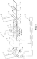
Figure 1 is a schematic view of an arrangement arranged in accordance with a preferred embodiment of the present invention; -
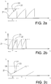
Figure 2a is a diagram that shows a control function in accordance with the invention; -
Figure 2b is a diagram that shows an alternative control function; and -
Figure 2c is a diagram that shows yet another alternative control function. -
Figure 1 is a schematic and simplified view of an arrangement 1 for manufacturing absorbent products, that is arranged in accordance with a preferred embodiment of the present invention. More specifically, the arrangement 1 is arranged for manufacturing absorbent products that start out as a first essentially continuous web ofmaterial 2, which is fed forward in a known way from a roll (not shown) or the like, in a direction that is indicated by an arrow inFigure 1 . - According to the preferred embodiment, the first web of
material 2 consists of a backing layer for a disposable nappy, that is a material of the type that is non-permeable to liquid or that has at least a high resistance to the penetration of liquid, but which, however, is breathable. For this purpose, the first web ofmaterial 2 consists suitably of a thin and waterproof plastic film of, for example, polyethylene, polypropylene or polyester. Alternatively, a laminate of non-woven material and plastic film or other suitable and previously-known layers of material can be utilized as a liquid-tight backing layer. - The first web of
material 2 can be fed forward by means of tworollers 3, 4 which are arranged to give the first web ofmaterial 2, that will become the backing layer, a certain given feed speed v1. -
Figure 1 also shows that the first web ofmaterial 2 is processed in such a way that it comprises a printedmotif 5. Thismotif 5 is suitably pre-printed on the first web ofmaterial 2. In addition, themotif 5 is applied in such a way that it recurs at a certain predetermined distance in such a way that one and the same motif is provided on each individual product that is manufactured from the first web ofmaterial 2. In addition, themotif 5 is indicated by broken lines inFigure 1 to indicate that it is printed on the underside of the first web ofmaterial 2. In the finished product, the final position of the printedmotif 5 will thus be in a predetermined position on the back of the product. - The
motif 5 is printed at certain given regular intervals and is intended to be synchronized, which means that the final position of themotif 5 is intended to be in the same position on each individually manufactured product of the type in question. For this purpose, the first web ofmaterial 2 is provided with a number of reference marks orsynchronization marks 6, suitably in the form of relatively short lines that are suitably pre-printed onto the first web ofmaterial 2. In the embodiment shown inFigure 1 , the synchronization marks 6 are printed on the underside of the first web ofmaterial 2. The invention is not, however, restricted to this, but it is possible to print the synchronization marks 6 on both sides of the first web ofmaterial 2. - In
Figure 1 , the synchronization marks 6 are also indicated by broken lines, in order to indicate that they are printed on the underside of the first web ofmaterial 2. As will be described in detail below, the object of eachsynchronization mark 6 is to constitute a detectable reference element, by means of which various work elements and process steps that are carried out by means of the arrangement 1 are synchronized correctly in relation to each printedmotif 5. In this way, themotif 5 can be positioned in the correct position on the finished product. - In the embodiment that is shown in
Figure 1 , a processed element in the first web ofmaterial 2 is utilized, in the form of a printedmotif 5. It should, however, be noted that the principle behind the invention is not limited to only the case when a printed motif is utilized. In other words, the invention can also be used for other positioned elements in the form of patterns, embossing, applications and ornamentation that constitute processing of the first web ofmaterial 2. Similarly, the principle behind the invention can be used for elements that consist of embossed patterns, folds, notches, holes and similar elements that are intended to be positioned in a predetermined, that is "synchronized", way on a finished product. - As shown in
Figure 1 , the first web ofmaterial 2 can be divided into a certain nominal division length LN, that is a length that is defined between twotransverse positions Figure 1 , the nominal division length LN consists in particular of a product length that corresponds to the front edge and back edge of a finished product. Thesepositions Figure 1 . However, these lines are not printed on the first web ofmaterial 2. - Each printed
motif 5 is placed in a position that is in a given and predetermined relationship to therespective synchronization mark 6. This means that eachsynchronization mark 6 is printed at a regularly recurring distance LS that corresponds to the regular intervals of the printedmotif 5. - As shown in
Figure 1 in a schematic and simplified way, the first web ofmaterial 2 is fed through aprocessing apparatus 9 where a number of work elements and process steps are carried out in a way that is already known. These work elements can comprise, for example, the application of various types of absorbent material, wadding material and the like, and any other material and components such as, for example, elastic, adhesive tape and the like. The work elements that are carried out in theprocessing apparatus 9 can also comprise folding, cutting, ultrasound welding and other processing steps. The manufacture of absorbent products by means of a series of such work elements is already known, and for this reason will not be described here in detail. As an example, however, reference can be made to the said patent documentWO 00/59429 - Still with reference to
Figure 1 , it can be noted that the first web ofmaterial 2 has passed a detectingdevice 10 just before it is fed into theprocessing apparatus 9. In a way that will be described in detail below, the detectingdevice 10 is arranged to detect the presence of eachsynchronization mark 6. The feeding of the first web ofmaterial 2 is carried out by means of a feeding device that preferably consists of asuction conveyor 11 which is a known feeding device that can be controlled to feed forward the first web ofmaterial 2 at a given feed speed v2. In addition, the first web ofmaterial 2 is fed past a gluingstation 12 at which adhesive is applied in order to enable a subsequent outer layer to be glued on, in the way that will be described below. - The detecting
device 10 consists preferably of a suitable device for optical inspection, according to the embodiment in the form of a video camera that is arranged in association with the first web ofmaterial 2. The detectingdevice 10 is arranged in such a way that it continually inspects and records images along the underside of the first web ofmaterial 2 as shown schematically inFigure 1 . For this purpose, the detectingdevice 10 comprises a set of light-sensitive elements, by means of which it records the light transmission from the first web ofmaterial 2 while this is moved in relation to the detectingdevice 10. - In addition, the detecting
device 10 is connected to a computer-basedcontrol unit 13. Information from the detectingdevice 10 is transmitted in this way to thecontrol unit 13, which in turn is provided with software for image processing that is arranged to detect eachsynchronization mark 6 that passes over the detectingdevice 10. In addition, thecontrol unit 13 is connected, in a way that will be described in detail below, to a speed-control device 14 for controlling the speed v1 at which the first web ofmaterial 2 is fed forward. Thecontrol unit 13 is also connected to thesuction conveyor 11 for controlling the speed v2 of this. - According to an alternative embodiment, the detecting
device 10 can be, for example, a CCD camera ("charged coupled device"), i.e. with a set of light-sensitive sensors arranged in one or more rows. By means of this arrangement, the position of eachsynchronization mark 6 can be detected. According to yet another alternative embodiment, the detecting device can be based on, for example, laser technology, that is with a laser light source that is utilized in conjunction with a light-sensitive detector to detect the position of eachsynchronization mark 6. According to yet another variant, the synchronization mark can consist of an electronically detectable sensor, for example of the transponder type, that is applied on the first web ofmaterial 2 and with the abovementioned regular intervals LS. Such a synchronization mark can then be read by a detecting device that comprises a radio transmitter and radio receiver for this purpose in a known way. According to yet another alternative embodiment, the said synchronization marks can be printed with magnetic ink that can then be detected by a sensor that detects magnetism. - When the first web of
material 2 has been fed past the detectingdevice 10, it meets a second web ofmaterial 15, according to the embodiment in the form of an essentially liquid-permeable layer that is intended to form an outer layer of the finished product. For this reason, the second web ofmaterial 15 consists suitably of a non-woven material with a soft and smooth surface, such as, for example, a spun bond material of polypropylene fibre. Other examples of materials that are suitable for constituting the outer layer are perforated plastic films, such as, for example, a perforated polyester film. - The second web of
material 15 is thus joined to the first web of material 2 (together with any additional layers of material and other components that are added in association with theprocessing apparatus 9 as described above) for example by means of the adhesive that was previously applied at the gluingstation 12. In this way, a complete web ofmaterial 16 is created, intended to define a number of manufactured products, which is fed forward in a direction that is indicated by an arrow inFigure 1 and taken up and fed forward by means of additional driving units, for example in the form of tworotating feeding rollers material 16. In this way, the complete web ofmaterial 16 can be fed forward. - After the assembly with the second web of
material 15, a complete continuous web ofmaterial 16 is thus created, consisting of a number of finished absorbent products that are still joined together. This web ofmaterial 16 is finally fed past a cuttingstation 19, suitably of the "cross-cutter" type, where cutting is carried out at positions that essentially correspond to theimaginary boundary lines absorbent products 20. - With reference again to the detecting
device 10, it can be noted in particular that it is arranged to detect the position of eachsynchronization mark 6. Information regarding a detected position for a givensynchronization mark 6 is then used for various process steps that, for example, are carried out in theprocessing apparatus 9 in order to ensure that the printedmotif 5 is always positioned in a correct position on eachfinished product 20. For this purpose, thecontrol unit 13 is arranged with a virtual data-based reference function or master function, which will now be described with reference initially toFigure 2a . - The virtual master function is a cyclic clock that preferably turns one revolution per
product 20. As described in detail below, the master function is not limited to these regular intervals only. An event-controlled reading off of this clock can be interpreted as the relative position of the event in question in relation to a fixed point on the product in question, that is in relation to a type of virtual zero point or reference for the product.Figure 2a shows the virtual master function in the form of a ramp-like curve 21 that recurs at regular intervals. - The invention is based on the basic principle that the detecting
device 10 is utilized first to detect aparticular synchronization mark 6 along the first web ofmaterial 2. When asynchronization mark 6 is found, thecontrol unit 13 is used to detect in what position along thevirtual master function 21 thesynchronization mark 6 is located. Information about the actual position of thevirtual master function 21 is thus recorded by means of thecontrol unit 13. Thereafter, thecontrol unit 13 compares the actual position of the virtual master function (actual value) with an expected position (desired value). The speed v1 of the first web ofmaterial 2 is then changed in relation to the speed v2 of thesuction conveyor 11 in response to any deviation between the actual position and the expected position. The slower the speed v1 in comparison with v2, the more the material in the first web ofmaterial 2 will be stretched. This is then utilized to obtain a correct synchronization of the first web ofmaterial 2. -
Figure 2a shows the said master function or reference function in the form of a ramp-like curve 21 that recurs at regular intervals and that symbolizes a periodic clock that is utilized for detecting eachsynchronization mark 6. For this reason, thecurve 21 is drawn in an xy-coordinate system where the x-axis corresponds to the time t, and where a period in thecurve 21 corresponds to the time T that it takes for a nominal division length LN of the material in question to pass the detectingdevice 10. In addition, the y-axis corresponds to a length L for the first web ofmaterial 2, with a maximal value LN of thecurve 21 corresponding to the length of each product. Thecurve 21 indicates in a schematic way a rise from a zero value that indicates one end of a product to a maximal value LN that indicates the other end of the product and that, according to the described embodiment, corresponds to the length of the product. - According to the invention, a value of the position of the virtual master function that has been read off (when a
synchronization mark 6 has just been detected) is thus compared periodically with an expected position along the virtual master function. The expected value, that is the desired value, is indicated inFigure 2 by thereference numeral 22 and corresponds to the printedmotif 5 being positioned correctly in its intended place on the finished product. The precise position for this desiredvalue 22 is determined by a number of factors, such as, for example, the equipment comprised in the arrangement 1, the dimensions of the comprised material, the process speed, etc. Thecurve 21 with its desiredvalue 22 thus consists of predefined data that is stored in thecontrol unit 13. For this reason, the reference function or master function that is illustrated by thecurve 21 can be said to be "virtual", as it is generated and stored in the form of software in thecontrol unit 13. -
Figure 2b shows an alternative embodiment of the invention, in which thevirtual master function 21 is arranged in such a way that two periods in thecurve 21 correspond to the time T that it takes for a nominal division length LN of the material in question to pass the detectingdevice 10.Figure 2c shows yet another embodiment of the invention in which thevirtual master function 21 is arranged in such a way that a period in thecurve 21 corresponds to twice the time T that it takes for a nominal division length LN of the material in question to pass the detectingdevice 10. - Taken as a whole, as illustrated by
Figures 2a, 2b and 2c , a basic principle behind the invention is that themaster function 21 consists of a cyclic clock where the number of cycles T perproduct 20, or alternatively the number ofproducts 20 per cycle T, consists of integers. In all the embodiments that are shown inFigures 2a, 2b and 2c , the principle is used that detection of a givensynchronization mark 6 is carried out using the detectingdevice 10. This results in the recording of a position along thecurve 21 that corresponds to this detectedsynchronization mark 6. This position then constitutes an actual value that is indicated schematically by thereference numeral 23 inFigures 2a, 2b, 2c . As the length of the period T for thecurve 21 can be said to have a given relationship to the product length of each product, theactual value 23 will consist of a numerical value corresponding to a certain proportion of the total product length. - In addition, the
control unit 13 is arranged to compare the desiredvalue 22 and the actual value 23 (that is the actual position) that was recorded during the detection of aparticular synchronization mark 6. According to the examples that are shown inFigures 2a, 2b and 2c , there is a difference between the desiredvalue 22 and theactual value 23. This difference can be expressed as a difference between the proportion of the whole product length that corresponds to the desiredvalue 22 minus the proportion of the product length that corresponds to theactual value 23. If there is a relatively large difference between the desiredvalue 22 and the actual value 23 (as shown in, for example,Figure 2a ), the printedmotif 5 would be positioned on the first web ofmaterial 2 displaced somewhat in relation to its intended position, that is themotif 5 would not then be correctly synchronized. For this reason, it is an underlying principle behind the invention that the position of the printedmotif 5 on thefinished product 20 is adjusted by stretching the first web ofmaterial 2 if there is such a deviation between the desiredvalue 22 and the measuredvalue 23. For this reason, the synchronization marks 6 are pre-printed on the first web ofmaterial 2 in such a way that they recur at regular intervals LS that are somewhat shorter than the intended product length LN. This means that the distance LS between two consecutive synchronization marks 6 is shorter than the product length LN, which in turn corresponds to the intended final length of thefinished product 20. The fact that the distance LS between twosynchronization marks 6 is shorter than the product length LN makes it possible to stretch the first web ofmaterial 2 to a certain extent, in order in this way to position the printedmotif 5 so that, in its final position, it is in the correct position on thefinished product 20. - According to the embodiment shown, the abovementioned stretching of the first web of
material 2 is achieved by a control of the speed of the first speed-control device 14, which in turn controls the feed speed v1 for the first web ofmaterial 2. More specifically, thecontrol unit 13 is arranged to control the speed-control device 14 in such a way that the first web ofmaterial 2 is given a speed v1 that is somewhat lower than the speed v2 of thesuction conveyor 11. This leads in turn to a stretching of the material in the first web ofmaterial 2 when it runs through theprocess apparatus 9. In this way, the position of the printedmotif 5 on the finished product and thereby also the position of therespective synchronization mark 6, is adjusted in such a way that the deviation between the desiredvalue 22 and theactual value 23 relating to the position of thesynchronization mark 6 is eliminated. - According to the embodiment, the distance LS between two consecutive synchronization marks 6 is of the order of 2% shorter than the product length LN. This makes it possible to utilize the natural elasticity of the first web of
material 2 for stretching it in accordance with the abovementioned principles. The invention is, however, not limited to any specific ratio between the product length LP and the distance between synchronization marks LS, but instead this ratio can vary, depending upon the comprised material and which type of process apparatus is utilized. Nor is the invention limited to the nominal division lengths having to be connected to the product length, but instead other divisions of the first web ofmaterial 2 are possible within the framework of the invention. - To sum up, the invention is based on a detection of synchronization marks 6, the position of which is detected and utilized for synchronizing a printed
motif 5 in the correct intended position on a finished product. The synchronization is carried out using a virtual reference function or "master" function that is stored in thecontrol unit 13 and that is arranged to provide references in order to make it possible to stretch the first web ofmaterial 2 if a deviation is recorded between an actual position and the expected position of eachsynchronization mark 6. In this way, a simple and accurate process is obtained for synchronizing the printedmotif 5. - The invention is not limited to what is described above, various embodiments being possible within the framework of the patent claims. For example, the invention is particularly suitable for use in association with a manufacturing process for making absorbent products such as nappies, incontinence pads, sanitary towels and panty liners, but is not limited only to this type of product, being able, in principle, to be utilized in other manufacturing processes that are based on an essentially continuous web of material being divided into a certain product length and where a printed motif or other similar process is synchronized in the correct position.
- The invention is particularly suitable for use with the applications where the first web of
material 2 consists of a material intended to form a backing layer in a nappy. Such a material then consists suitably of a plastic film that is non-permeable to liquid, which is suitable for the abovementioned stretching procedure and is also suitable for printing with high quality colour motifs. The invention can, however, be used with other material than just the backing layer for nappies, for example other elastic and stretchable webs of material, for example non-woven material, that is fibrous materials with fibres such as for example polyolefins, that is polymer material such as polyethylene and polypropylene, or alternatively polyester, nylon or the like. The invention can also be utilized when the first web of material consists of some other type of synthetic or textile material. The invention can also be used for different types of laminates comprising varying numbers of layers of material. - Regarding the printed
motif 5, this can be provided by being pre-printed onto the first web ofmaterial 2. Alternatively, the actual manufacturing process that is obtained with theprocess apparatus 9 can comprise a process for printing the motif. - In addition, it can be noted, with reference to
Figure 2 , that a period length T in thereference function 21 can correspond to a product length, as described above. Alternatively, a period length T can correspond to two or more product lengths, or a certain proportion of a product length. This means that the synchronization marks can be positioned in a corresponding way, for example in every other position in comparison with what is shown inFigure 1 . - With reference to
Figure 2 , it can be pointed out that the invention is not limited to a virtual master function where a period corresponds clearly to a product length. Alternatively, the invention can be arranged in such a way that a given product length corresponds to two or more synchronization marks and thus also two or more periods in the virtual master function.
Claims (14)
- Method for synchronized positioning of at least one essentially continuous web of material (2), for manufacturing absorbent products (20) that comprise printed motifs (5) or similar processed elements, which said web of material (2) is intended to be divided into nominal division lengths (LN) and comprises synchronization marks (6) that recur at regular intervals (LS), which method comprises:feeding the said web of material (2) into a production apparatus (9) at a first speed (v1);processing in the said production apparatus (9) with various process steps for the said manufacture, with the said web of material (2) being fed forward at a second speed (v2); anddetection of each synchronization mark (6) for positioning the respective motif (5) in a predetermined position on each product (20);characterized in that the said method comprises:generation of a reading off of the actual position (actual value) (23) of a virtual master function (21) upon the said detection, which said master function (21) consists of a cyclic clock where the number of cycles (T) per product (20), or alternatively the number of products (20) per cycle (T), consists of an integer;comparison between the said actual position (actual value) (23) and the expected position (desired value) (22) of the virtual master function (21); andstretching of the said web of material (2) in response to any deviation between the said actual position (actual value) (23) and the said expected position (desired value) (22), with the aim of minimizing the said deviation.
- Method according to Claim 1, characterized in that the said comparison is carried out via a reference function (21) that is generated and stored in a computer-based control unit (13).
- Method according to Claim 1 or 2, characterized in that the said regular interval (LS) between the synchronization marks is of the order of 2% shorter than the said nominal division length (LN).
- Method according to any one of the preceding claims, characterized in that the said stretching is achieved by a control of the first speed (v1) to a lower value than the said second speed (v2).
- Method according to any one of the preceding claims, characterized in that the nominal division length (LN) consists of a predetermined product length (LP) for the said product (20).
- Method according to any one of the preceding claims, characterized in that the said product (20) consists of an absorbent product and in that the method comprises the provision of a web of material (2) in the form of a layer for such an absorbent product.
- Method according to Claim 6, characterized in that the web of material (2) consists of a backing layer for the said product (20).
- Method according to Claim 6, characterized in that the web of material (2) consists of a side panel, a top layer, wadding material or similar material components in the said product (20).
- Method according to Claim 6, characterized in that the web of material (2) consists of a side panel in the said product (20).
- Method according to any one of the preceding claims, characterized in that it comprises:feeding out of a complete web of material (15) that consists of a continuous row of a number of products; andcutting of the said complete web of material (15) into individual products (20) with the said nominal division length (LN).
- Arrangement for synchronized positioning of at least one essentially continuous web of material (2) for manufacturing absorbent products (20) that comprise printed motifs (5) or similar processed elements, which said web of material (2) is intended to be divided into nominal division lengths (LN) and comprises synchronization marks (6) that recur at regular intervals (LS), which arrangement additionally comprises:a first speed-control device (14) for feeding the said web of material (2) into a production apparatus (9) at a first speed (v1), which production apparatus is arranged to carry out various process steps for the said manufacture;a second speed-control device (12) for feeding the said web of material (2) through the said process steps at a second speed (v2);a detector (10) for detecting the respective synchronization marks (6); anda computer-based control unit (13) arranged for the said synchronization, whereby the respective motifs (5) are positioned in a predetermined position on each product (20), characterized in that the control unit (13) is arranged to initiate a reading off of the actual position (actual value) (23) of a virtual master function (21) upon the said detection, which said master function (21) consists of a cyclic clock where the number of cycles (T) per product (20), or alternatively the number of products (20) per cycle (T), consists of an integer, for comparison between the said actual position (actual value) (23) and the expected position (desired value) (22) of the virtual master function (21), and for stretching the said web of material (2) in response to any deviation between the said actual position (actual value) (23) and the said expected position (desired value) (22), with the aim of minimizing the said deviation.
- Arrangement according to Claim 11, characterized in that the said master function (21) is stored in the form of software in the said control unit (13).
- Arrangement according to Claim 11 or 12, characterized in that the said regular interval (LS) between the synchronization marks is of the order of 2% shorter than the said nominal division length (LN).
- Arrangement according to any one of Claims 11-13, characterized in that the control unit (13) is arranged to carry out the said stretching by a control of the first speed-control device (14) and the second speed-control device (12) so that the said first speed (v1) is given a lower value than the said second speed (v2).
Applications Claiming Priority (1)
| Application Number | Priority Date | Filing Date | Title |
|---|---|---|---|
| PCT/SE2006/000515 WO2007126345A1 (en) | 2006-04-27 | 2006-04-27 | Method and arrangement for synchronized positioning of at least one essentially continuous material web . |
Publications (3)
| Publication Number | Publication Date |
|---|---|
| EP2010443A1 EP2010443A1 (en) | 2009-01-07 |
| EP2010443A4 EP2010443A4 (en) | 2010-01-27 |
| EP2010443B1 true EP2010443B1 (en) | 2017-05-17 |
Family
ID=38655784
Family Applications (1)
| Application Number | Title | Priority Date | Filing Date |
|---|---|---|---|
| EP06733370.8A Not-in-force EP2010443B1 (en) | 2006-04-27 | 2006-04-27 | Method and arrangement for synchronized positioning of at least one essentially continuous material web . |
Country Status (10)
| Country | Link |
|---|---|
| US (1) | US8168254B2 (en) |
| EP (1) | EP2010443B1 (en) |
| JP (1) | JP4920746B2 (en) |
| CN (1) | CN101405209B (en) |
| AU (1) | AU2006342827A1 (en) |
| BR (1) | BRPI0621627A2 (en) |
| MX (1) | MX2008011255A (en) |
| MY (1) | MY148922A (en) |
| TN (1) | TNSN08363A1 (en) |
| WO (1) | WO2007126345A1 (en) |
Families Citing this family (15)
| Publication number | Priority date | Publication date | Assignee | Title |
|---|---|---|---|---|
| US7918389B2 (en) * | 2007-05-15 | 2011-04-05 | Corning Incorporated | Method and system for tracking unfinished ceramic structures during manufacture |
| US8145343B2 (en) | 2009-06-02 | 2012-03-27 | The Procter & Gamble Company | Systems and methods for controlling registration of advancing substrates in absorbent article converting lines |
| US8145344B2 (en) | 2009-06-02 | 2012-03-27 | The Procter & Gamble Company | Systems and methods for controlling phasing of advancing substrates in absorbent article converting lines |
| US8145338B2 (en) | 2009-06-02 | 2012-03-27 | The Procter & Gamble Company | Systems and methods for detecting and rejecting defective absorbent articles from a converting line |
| WO2014150750A1 (en) | 2013-03-15 | 2014-09-25 | The Iams Company | Method and apparatus for performing multiple tasks on a web of material |
| JP5760111B1 (en) * | 2014-03-27 | 2015-08-05 | ユニ・チャーム株式会社 | Absorbent article manufacturing apparatus and manufacturing method |
| US10119225B2 (en) | 2014-04-15 | 2018-11-06 | Gpcp Ip Holdings Llc | Systems for controlling a manufacturing line used to convert a paper web into paper products by reading marks on the paper web |
| AT515932B1 (en) * | 2014-10-27 | 2016-01-15 | Bernecker & Rainer Ind Elektronik Gmbh | Method and device for detecting a printed mark |
| PL3051013T3 (en) * | 2015-01-30 | 2019-05-31 | Reifenhaeuser Gmbh & Co Kg Maschf | Method for guiding a nonwoven web |
| US20170128274A1 (en) | 2015-11-11 | 2017-05-11 | The Procter & Gamble Company | Methods and Apparatuses for Registering Substrates in Absorbent Article Converting Lines |
| JP6837317B2 (en) * | 2016-11-14 | 2021-03-03 | Ykk株式会社 | Tape-shaped member transfer device |
| CN110914180B (en) * | 2017-06-05 | 2021-07-13 | 富士商工机械株式会社 | Web material attaching device |
| CN109024005B (en) * | 2018-08-29 | 2020-07-21 | 温州职业技术学院 | Cloth pastes knurling automation equipment |
| FR3097462B1 (en) * | 2019-06-21 | 2021-07-02 | Lectra | Method of placing pieces to be cut automatically from a patterned fabric |
| CN113696517A (en) * | 2021-08-18 | 2021-11-26 | 北京光华纺织集团有限公司 | Planar coated fabric with indication mark and coating and applying process thereof |
Family Cites Families (13)
| Publication number | Priority date | Publication date | Assignee | Title |
|---|---|---|---|---|
| US3556509A (en) * | 1968-08-21 | 1971-01-19 | Harris Intertype Corp | Printed web ribbon registration control system |
| US4795513A (en) * | 1983-02-01 | 1989-01-03 | Adolph Coors Company | Method and apparatus for producing a laminated composite material having perforated inner layer |
| US4837715A (en) * | 1987-01-27 | 1989-06-06 | Kimberly-Clark Corporation | Method and apparatus for detecting the placement of components on absorbent articles |
| JP3765580B2 (en) | 1994-04-13 | 2006-04-12 | ブランスタール・プリンティング・パルティシパチオン・エスタブリッシュマーン | Apparatus and method for stacking and upgrading a plurality of long sheets |
| JPH09138115A (en) | 1995-11-14 | 1997-05-27 | Mitsutoyo Corp | Scanning optical dimension-measuring device |
| US5930139A (en) * | 1996-11-13 | 1999-07-27 | Kimberly-Clark Worldwide, Inc. | Process and apparatus for registration control of material printed at machine product length |
| JPH10239019A (en) | 1997-02-28 | 1998-09-11 | Yaskawa Electric Corp | Moving body position measuring device |
| AU5803898A (en) | 1997-12-19 | 1999-07-12 | Procter & Gamble Company, The | Registration system for phasing simultaneously advancing webs of material havingvariable pitch lengths |
| US6354984B1 (en) * | 1999-04-02 | 2002-03-12 | Kimberly-Clark Worldwide, Inc. | Indirect registration of elements of web-derived product |
| JP3523119B2 (en) | 1999-07-21 | 2004-04-26 | 日本信号株式会社 | Vehicle length detection method and vehicle length detection device |
| US6869386B2 (en) | 2002-06-26 | 2005-03-22 | The Procter & Gamble Company | Method for manufacturing discrete articles from a material web using synchronized servo-actuated operational units |
| JP4246020B2 (en) | 2003-09-08 | 2009-04-02 | 王子製紙株式会社 | Method for manufacturing absorbent article |
| US6957160B2 (en) * | 2003-12-09 | 2005-10-18 | The Procter & Gamble Company | Method and system for registering pre-produced webs with variable pitch length |
-
2006
- 2006-04-27 AU AU2006342827A patent/AU2006342827A1/en not_active Abandoned
- 2006-04-27 US US12/297,555 patent/US8168254B2/en active Active
- 2006-04-27 BR BRPI0621627-7A patent/BRPI0621627A2/en not_active IP Right Cessation
- 2006-04-27 JP JP2009507619A patent/JP4920746B2/en not_active Expired - Fee Related
- 2006-04-27 CN CN2006800540060A patent/CN101405209B/en not_active Expired - Fee Related
- 2006-04-27 WO PCT/SE2006/000515 patent/WO2007126345A1/en active Application Filing
- 2006-04-27 EP EP06733370.8A patent/EP2010443B1/en not_active Not-in-force
- 2006-04-27 MX MX2008011255A patent/MX2008011255A/en not_active Application Discontinuation
-
2007
- 2007-04-13 MY MYPI20070581A patent/MY148922A/en unknown
-
2008
- 2008-09-19 TN TNP2008000363A patent/TNSN08363A1/en unknown
Also Published As
| Publication number | Publication date |
|---|---|
| AU2006342827A1 (en) | 2007-11-08 |
| EP2010443A1 (en) | 2009-01-07 |
| JP4920746B2 (en) | 2012-04-18 |
| CN101405209A (en) | 2009-04-08 |
| MY148922A (en) | 2013-06-14 |
| TNSN08363A1 (en) | 2009-12-29 |
| EP2010443A4 (en) | 2010-01-27 |
| BRPI0621627A2 (en) | 2011-12-13 |
| JP2009535617A (en) | 2009-10-01 |
| US8168254B2 (en) | 2012-05-01 |
| CN101405209B (en) | 2012-11-28 |
| US20090176008A1 (en) | 2009-07-09 |
| MX2008011255A (en) | 2008-09-10 |
| WO2007126345A1 (en) | 2007-11-08 |
Similar Documents
| Publication | Publication Date | Title |
|---|---|---|
| EP2010443B1 (en) | Method and arrangement for synchronized positioning of at least one essentially continuous material web . | |
| AU2006342829B8 (en) | Method and arrangement for detection of a sychronizing mark being used in sychronized positioning of at least one essentially continuous material web | |
| EP1667843B1 (en) | System and method for incorporating graphics into absorbent articles | |
| US6092002A (en) | Variable tension process and apparatus for continuously moving layers | |
| KR100522333B1 (en) | Process and apparatus for registering continuously moving stretchable layers | |
| CA2267142C (en) | Process and apparatus for registration control of material printed at machine product length | |
| RU2152310C1 (en) | Method of controlled matching of assemblage of elements of first and second continuously moving belts ( versions ) and method of controlled matching of assemblage of test marks of first and second moving belts | |
| RU2316300C2 (en) | Method and apparatus for manufacture of disposable absorption articles | |
| WO2000045767A1 (en) | Processes and apparatus for making disposable absorbent articles | |
| US20030234069A1 (en) | Processes and apparatus for making disposable absorbent articles | |
| RU2421390C2 (en) | Method and device for synchronised positioning of, at least, one, in fact, continuous material belt | |
| RU2401654C2 (en) | Method and device for detecting synchronising mark, used in synchronised positioning of at least one in essence continuous material canvas | |
| KR100466557B1 (en) | Process and apparatus for registering a continuously moving, treatable layer with another layer |
Legal Events
| Date | Code | Title | Description |
|---|---|---|---|
| PUAI | Public reference made under article 153(3) epc to a published international application that has entered the european phase |
Free format text: ORIGINAL CODE: 0009012 |
|
| 17P | Request for examination filed |
Effective date: 20081111 |
|
| AK | Designated contracting states |
Kind code of ref document: A1 Designated state(s): AT BE BG CH CY CZ DE DK EE ES FI FR GB GR HU IE IS IT LI LT LU LV MC NL PL PT RO SE SI SK TR |
|
| AX | Request for extension of the european patent |
Extension state: AL BA HR MK YU |
|
| A4 | Supplementary search report drawn up and despatched |
Effective date: 20091230 |
|
| 17Q | First examination report despatched |
Effective date: 20101007 |
|
| DAX | Request for extension of the european patent (deleted) | ||
| GRAP | Despatch of communication of intention to grant a patent |
Free format text: ORIGINAL CODE: EPIDOSNIGR1 |
|
| INTG | Intention to grant announced |
Effective date: 20161201 |
|
| GRAS | Grant fee paid |
Free format text: ORIGINAL CODE: EPIDOSNIGR3 |
|
| GRAA | (expected) grant |
Free format text: ORIGINAL CODE: 0009210 |
|
| AK | Designated contracting states |
Kind code of ref document: B1 Designated state(s): AT BE BG CH CY CZ DE DK EE ES FI FR GB GR HU IE IS IT LI LT LU LV MC NL PL PT RO SE SI SK TR |
|
| REG | Reference to a national code |
Ref country code: GB Ref legal event code: FG4D |
|
| REG | Reference to a national code |
Ref country code: CH Ref legal event code: EP |
|
| REG | Reference to a national code |
Ref country code: IE Ref legal event code: FG4D |
|
| REG | Reference to a national code |
Ref country code: AT Ref legal event code: REF Ref document number: 894241 Country of ref document: AT Kind code of ref document: T Effective date: 20170615 |
|
| REG | Reference to a national code |
Ref country code: DE Ref legal event code: R096 Ref document number: 602006052566 Country of ref document: DE |
|
| REG | Reference to a national code |
Ref country code: NL Ref legal event code: MP Effective date: 20170517 |
|
| REG | Reference to a national code |
Ref country code: LT Ref legal event code: MG4D |
|
| REG | Reference to a national code |
Ref country code: AT Ref legal event code: MK05 Ref document number: 894241 Country of ref document: AT Kind code of ref document: T Effective date: 20170517 |
|
| PG25 | Lapsed in a contracting state [announced via postgrant information from national office to epo] |
Ref country code: ES Free format text: LAPSE BECAUSE OF FAILURE TO SUBMIT A TRANSLATION OF THE DESCRIPTION OR TO PAY THE FEE WITHIN THE PRESCRIBED TIME-LIMIT Effective date: 20170517 Ref country code: GR Free format text: LAPSE BECAUSE OF FAILURE TO SUBMIT A TRANSLATION OF THE DESCRIPTION OR TO PAY THE FEE WITHIN THE PRESCRIBED TIME-LIMIT Effective date: 20170818 Ref country code: LT Free format text: LAPSE BECAUSE OF FAILURE TO SUBMIT A TRANSLATION OF THE DESCRIPTION OR TO PAY THE FEE WITHIN THE PRESCRIBED TIME-LIMIT Effective date: 20170517 Ref country code: FI Free format text: LAPSE BECAUSE OF FAILURE TO SUBMIT A TRANSLATION OF THE DESCRIPTION OR TO PAY THE FEE WITHIN THE PRESCRIBED TIME-LIMIT Effective date: 20170517 Ref country code: AT Free format text: LAPSE BECAUSE OF FAILURE TO SUBMIT A TRANSLATION OF THE DESCRIPTION OR TO PAY THE FEE WITHIN THE PRESCRIBED TIME-LIMIT Effective date: 20170517 |
|
| PG25 | Lapsed in a contracting state [announced via postgrant information from national office to epo] |
Ref country code: BG Free format text: LAPSE BECAUSE OF FAILURE TO SUBMIT A TRANSLATION OF THE DESCRIPTION OR TO PAY THE FEE WITHIN THE PRESCRIBED TIME-LIMIT Effective date: 20170817 Ref country code: PL Free format text: LAPSE BECAUSE OF FAILURE TO SUBMIT A TRANSLATION OF THE DESCRIPTION OR TO PAY THE FEE WITHIN THE PRESCRIBED TIME-LIMIT Effective date: 20170517 Ref country code: IS Free format text: LAPSE BECAUSE OF FAILURE TO SUBMIT A TRANSLATION OF THE DESCRIPTION OR TO PAY THE FEE WITHIN THE PRESCRIBED TIME-LIMIT Effective date: 20170917 Ref country code: LV Free format text: LAPSE BECAUSE OF FAILURE TO SUBMIT A TRANSLATION OF THE DESCRIPTION OR TO PAY THE FEE WITHIN THE PRESCRIBED TIME-LIMIT Effective date: 20170517 Ref country code: SE Free format text: LAPSE BECAUSE OF FAILURE TO SUBMIT A TRANSLATION OF THE DESCRIPTION OR TO PAY THE FEE WITHIN THE PRESCRIBED TIME-LIMIT Effective date: 20170517 Ref country code: NL Free format text: LAPSE BECAUSE OF FAILURE TO SUBMIT A TRANSLATION OF THE DESCRIPTION OR TO PAY THE FEE WITHIN THE PRESCRIBED TIME-LIMIT Effective date: 20170517 |
|
| PG25 | Lapsed in a contracting state [announced via postgrant information from national office to epo] |
Ref country code: EE Free format text: LAPSE BECAUSE OF FAILURE TO SUBMIT A TRANSLATION OF THE DESCRIPTION OR TO PAY THE FEE WITHIN THE PRESCRIBED TIME-LIMIT Effective date: 20170517 Ref country code: SK Free format text: LAPSE BECAUSE OF FAILURE TO SUBMIT A TRANSLATION OF THE DESCRIPTION OR TO PAY THE FEE WITHIN THE PRESCRIBED TIME-LIMIT Effective date: 20170517 Ref country code: DK Free format text: LAPSE BECAUSE OF FAILURE TO SUBMIT A TRANSLATION OF THE DESCRIPTION OR TO PAY THE FEE WITHIN THE PRESCRIBED TIME-LIMIT Effective date: 20170517 Ref country code: RO Free format text: LAPSE BECAUSE OF FAILURE TO SUBMIT A TRANSLATION OF THE DESCRIPTION OR TO PAY THE FEE WITHIN THE PRESCRIBED TIME-LIMIT Effective date: 20170517 Ref country code: CZ Free format text: LAPSE BECAUSE OF FAILURE TO SUBMIT A TRANSLATION OF THE DESCRIPTION OR TO PAY THE FEE WITHIN THE PRESCRIBED TIME-LIMIT Effective date: 20170517 |
|
| REG | Reference to a national code |
Ref country code: DE Ref legal event code: R097 Ref document number: 602006052566 Country of ref document: DE |
|
| PLBE | No opposition filed within time limit |
Free format text: ORIGINAL CODE: 0009261 |
|
| STAA | Information on the status of an ep patent application or granted ep patent |
Free format text: STATUS: NO OPPOSITION FILED WITHIN TIME LIMIT |
|
| 26N | No opposition filed |
Effective date: 20180220 |
|
| PG25 | Lapsed in a contracting state [announced via postgrant information from national office to epo] |
Ref country code: SI Free format text: LAPSE BECAUSE OF FAILURE TO SUBMIT A TRANSLATION OF THE DESCRIPTION OR TO PAY THE FEE WITHIN THE PRESCRIBED TIME-LIMIT Effective date: 20170517 |
|
| PG25 | Lapsed in a contracting state [announced via postgrant information from national office to epo] |
Ref country code: MC Free format text: LAPSE BECAUSE OF FAILURE TO SUBMIT A TRANSLATION OF THE DESCRIPTION OR TO PAY THE FEE WITHIN THE PRESCRIBED TIME-LIMIT Effective date: 20170517 |
|
| REG | Reference to a national code |
Ref country code: CH Ref legal event code: PL |
|
| REG | Reference to a national code |
Ref country code: BE Ref legal event code: MM Effective date: 20180430 |
|
| REG | Reference to a national code |
Ref country code: IE Ref legal event code: MM4A |
|
| PG25 | Lapsed in a contracting state [announced via postgrant information from national office to epo] |
Ref country code: LU Free format text: LAPSE BECAUSE OF NON-PAYMENT OF DUE FEES Effective date: 20180427 |
|
| REG | Reference to a national code |
Ref country code: DE Ref legal event code: R082 Ref document number: 602006052566 Country of ref document: DE Representative=s name: ZACCO PATENTANWALTS- UND RECHTSANWALTSGESELLSC, DE Ref country code: DE Ref legal event code: R081 Ref document number: 602006052566 Country of ref document: DE Owner name: ESSITY HYGIENE AND HEALTH AKTIEBOLAG, SE Free format text: FORMER OWNER: SCA HYGIENE PRODUCTS AB, GOETEBORG/GOTENBURG, SE Ref country code: DE Ref legal event code: R082 Ref document number: 602006052566 Country of ref document: DE Representative=s name: HOFFMANN - EITLE PATENT- UND RECHTSANWAELTE PA, DE |
|
| PG25 | Lapsed in a contracting state [announced via postgrant information from national office to epo] |
Ref country code: BE Free format text: LAPSE BECAUSE OF NON-PAYMENT OF DUE FEES Effective date: 20180430 Ref country code: CH Free format text: LAPSE BECAUSE OF NON-PAYMENT OF DUE FEES Effective date: 20180430 Ref country code: LI Free format text: LAPSE BECAUSE OF NON-PAYMENT OF DUE FEES Effective date: 20180430 |
|
| PG25 | Lapsed in a contracting state [announced via postgrant information from national office to epo] |
Ref country code: IE Free format text: LAPSE BECAUSE OF NON-PAYMENT OF DUE FEES Effective date: 20180427 Ref country code: FR Free format text: LAPSE BECAUSE OF NON-PAYMENT OF DUE FEES Effective date: 20180430 |
|
| REG | Reference to a national code |
Ref country code: DE Ref legal event code: R082 Ref document number: 602006052566 Country of ref document: DE Representative=s name: HOFFMANN - EITLE PATENT- UND RECHTSANWAELTE PA, DE |
|
| PG25 | Lapsed in a contracting state [announced via postgrant information from national office to epo] |
Ref country code: TR Free format text: LAPSE BECAUSE OF FAILURE TO SUBMIT A TRANSLATION OF THE DESCRIPTION OR TO PAY THE FEE WITHIN THE PRESCRIBED TIME-LIMIT Effective date: 20170517 |
|
| PG25 | Lapsed in a contracting state [announced via postgrant information from national office to epo] |
Ref country code: PT Free format text: LAPSE BECAUSE OF FAILURE TO SUBMIT A TRANSLATION OF THE DESCRIPTION OR TO PAY THE FEE WITHIN THE PRESCRIBED TIME-LIMIT Effective date: 20170517 Ref country code: HU Free format text: LAPSE BECAUSE OF FAILURE TO SUBMIT A TRANSLATION OF THE DESCRIPTION OR TO PAY THE FEE WITHIN THE PRESCRIBED TIME-LIMIT; INVALID AB INITIO Effective date: 20060427 |
|
| PG25 | Lapsed in a contracting state [announced via postgrant information from national office to epo] |
Ref country code: CY Free format text: LAPSE BECAUSE OF FAILURE TO SUBMIT A TRANSLATION OF THE DESCRIPTION OR TO PAY THE FEE WITHIN THE PRESCRIBED TIME-LIMIT Effective date: 20170517 |
|
| PGFP | Annual fee paid to national office [announced via postgrant information from national office to epo] |
Ref country code: IT Payment date: 20210310 Year of fee payment: 16 |
|
| PGFP | Annual fee paid to national office [announced via postgrant information from national office to epo] |
Ref country code: GB Payment date: 20210331 Year of fee payment: 16 |
|
| PGFP | Annual fee paid to national office [announced via postgrant information from national office to epo] |
Ref country code: DE Payment date: 20210330 Year of fee payment: 16 |
|
| REG | Reference to a national code |
Ref country code: DE Ref legal event code: R119 Ref document number: 602006052566 Country of ref document: DE |
|
| GBPC | Gb: european patent ceased through non-payment of renewal fee |
Effective date: 20220427 |
|
| PG25 | Lapsed in a contracting state [announced via postgrant information from national office to epo] |
Ref country code: GB Free format text: LAPSE BECAUSE OF NON-PAYMENT OF DUE FEES Effective date: 20220427 Ref country code: DE Free format text: LAPSE BECAUSE OF NON-PAYMENT OF DUE FEES Effective date: 20221103 |
|
| PG25 | Lapsed in a contracting state [announced via postgrant information from national office to epo] |
Ref country code: IT Free format text: LAPSE BECAUSE OF NON-PAYMENT OF DUE FEES Effective date: 20220427 |