EP2010429B1 - Steuersystem für einlassverzerrung und wiederherstellung - Google Patents
Steuersystem für einlassverzerrung und wiederherstellung Download PDFInfo
- Publication number
- EP2010429B1 EP2010429B1 EP07753379A EP07753379A EP2010429B1 EP 2010429 B1 EP2010429 B1 EP 2010429B1 EP 07753379 A EP07753379 A EP 07753379A EP 07753379 A EP07753379 A EP 07753379A EP 2010429 B1 EP2010429 B1 EP 2010429B1
- Authority
- EP
- European Patent Office
- Prior art keywords
- generator
- generators
- flow
- inlet
- aircraft
- Prior art date
- Legal status (The legal status is an assumption and is not a legal conclusion. Google has not performed a legal analysis and makes no representation as to the accuracy of the status listed.)
- Not-in-force
Links
- 238000011084 recovery Methods 0.000 title description 7
- 230000004888 barrier function Effects 0.000 claims abstract description 18
- 230000006698 induction Effects 0.000 claims abstract description 11
- 238000000034 method Methods 0.000 claims abstract description 10
- 238000011144 upstream manufacturing Methods 0.000 claims description 13
- 230000004913 activation Effects 0.000 claims description 5
- 230000007704 transition Effects 0.000 claims description 3
- 230000003213 activating effect Effects 0.000 claims description 2
- 238000013459 approach Methods 0.000 abstract description 3
- 238000000926 separation method Methods 0.000 description 12
- 239000002245 particle Substances 0.000 description 4
- 230000035939 shock Effects 0.000 description 4
- 150000002500 ions Chemical class 0.000 description 3
- 238000012546 transfer Methods 0.000 description 3
- 230000015572 biosynthetic process Effects 0.000 description 2
- 230000007423 decrease Effects 0.000 description 2
- 230000037406 food intake Effects 0.000 description 2
- 239000000463 material Substances 0.000 description 2
- 230000009467 reduction Effects 0.000 description 2
- 239000007787 solid Substances 0.000 description 2
- RYGMFSIKBFXOCR-UHFFFAOYSA-N Copper Chemical compound [Cu] RYGMFSIKBFXOCR-UHFFFAOYSA-N 0.000 description 1
- 239000004642 Polyimide Substances 0.000 description 1
- 230000001133 acceleration Effects 0.000 description 1
- 238000007792 addition Methods 0.000 description 1
- 230000002411 adverse Effects 0.000 description 1
- 230000003466 anti-cipated effect Effects 0.000 description 1
- 230000008901 benefit Effects 0.000 description 1
- 230000000903 blocking effect Effects 0.000 description 1
- 239000011889 copper foil Substances 0.000 description 1
- 230000003111 delayed effect Effects 0.000 description 1
- 230000005684 electric field Effects 0.000 description 1
- 230000005611 electricity Effects 0.000 description 1
- 230000007613 environmental effect Effects 0.000 description 1
- 230000006870 function Effects 0.000 description 1
- 230000006872 improvement Effects 0.000 description 1
- 238000002347 injection Methods 0.000 description 1
- 239000007924 injection Substances 0.000 description 1
- 230000003993 interaction Effects 0.000 description 1
- 238000012423 maintenance Methods 0.000 description 1
- 238000005259 measurement Methods 0.000 description 1
- 238000012986 modification Methods 0.000 description 1
- 230000004048 modification Effects 0.000 description 1
- 230000007935 neutral effect Effects 0.000 description 1
- 230000000737 periodic effect Effects 0.000 description 1
- 229920001721 polyimide Polymers 0.000 description 1
- 230000001141 propulsive effect Effects 0.000 description 1
- 238000012360 testing method Methods 0.000 description 1
- 239000010409 thin film Substances 0.000 description 1
- 230000032258 transport Effects 0.000 description 1
- 239000013598 vector Substances 0.000 description 1
Images


Classifications
-
- B—PERFORMING OPERATIONS; TRANSPORTING
- B64—AIRCRAFT; AVIATION; COSMONAUTICS
- B64D—EQUIPMENT FOR FITTING IN OR TO AIRCRAFT; FLIGHT SUITS; PARACHUTES; ARRANGEMENT OR MOUNTING OF POWER PLANTS OR PROPULSION TRANSMISSIONS IN AIRCRAFT
- B64D33/00—Arrangement in aircraft of power plant parts or auxiliaries not otherwise provided for
- B64D33/02—Arrangement in aircraft of power plant parts or auxiliaries not otherwise provided for of combustion air intakes
-
- F—MECHANICAL ENGINEERING; LIGHTING; HEATING; WEAPONS; BLASTING
- F01—MACHINES OR ENGINES IN GENERAL; ENGINE PLANTS IN GENERAL; STEAM ENGINES
- F01D—NON-POSITIVE DISPLACEMENT MACHINES OR ENGINES, e.g. STEAM TURBINES
- F01D5/00—Blades; Blade-carrying members; Heating, heat-insulating, cooling or antivibration means on the blades or the members
- F01D5/12—Blades
- F01D5/14—Form or construction
- F01D5/141—Shape, i.e. outer, aerodynamic form
- F01D5/145—Means for influencing boundary layers or secondary circulations
-
- F—MECHANICAL ENGINEERING; LIGHTING; HEATING; WEAPONS; BLASTING
- F02—COMBUSTION ENGINES; HOT-GAS OR COMBUSTION-PRODUCT ENGINE PLANTS
- F02C—GAS-TURBINE PLANTS; AIR INTAKES FOR JET-PROPULSION PLANTS; CONTROLLING FUEL SUPPLY IN AIR-BREATHING JET-PROPULSION PLANTS
- F02C7/00—Features, components parts, details or accessories, not provided for in, or of interest apart form groups F02C1/00 - F02C6/00; Air intakes for jet-propulsion plants
- F02C7/04—Air intakes for gas-turbine plants or jet-propulsion plants
- F02C7/057—Control or regulation
-
- B—PERFORMING OPERATIONS; TRANSPORTING
- B64—AIRCRAFT; AVIATION; COSMONAUTICS
- B64D—EQUIPMENT FOR FITTING IN OR TO AIRCRAFT; FLIGHT SUITS; PARACHUTES; ARRANGEMENT OR MOUNTING OF POWER PLANTS OR PROPULSION TRANSMISSIONS IN AIRCRAFT
- B64D33/00—Arrangement in aircraft of power plant parts or auxiliaries not otherwise provided for
- B64D33/02—Arrangement in aircraft of power plant parts or auxiliaries not otherwise provided for of combustion air intakes
- B64D2033/0226—Arrangement in aircraft of power plant parts or auxiliaries not otherwise provided for of combustion air intakes comprising boundary layer control means
-
- B—PERFORMING OPERATIONS; TRANSPORTING
- B64—AIRCRAFT; AVIATION; COSMONAUTICS
- B64D—EQUIPMENT FOR FITTING IN OR TO AIRCRAFT; FLIGHT SUITS; PARACHUTES; ARRANGEMENT OR MOUNTING OF POWER PLANTS OR PROPULSION TRANSMISSIONS IN AIRCRAFT
- B64D33/00—Arrangement in aircraft of power plant parts or auxiliaries not otherwise provided for
- B64D33/02—Arrangement in aircraft of power plant parts or auxiliaries not otherwise provided for of combustion air intakes
- B64D2033/0266—Arrangement in aircraft of power plant parts or auxiliaries not otherwise provided for of combustion air intakes specially adapted for particular type of power plants
- B64D2033/0286—Arrangement in aircraft of power plant parts or auxiliaries not otherwise provided for of combustion air intakes specially adapted for particular type of power plants for turbofan engines
-
- F—MECHANICAL ENGINEERING; LIGHTING; HEATING; WEAPONS; BLASTING
- F05—INDEXING SCHEMES RELATING TO ENGINES OR PUMPS IN VARIOUS SUBCLASSES OF CLASSES F01-F04
- F05D—INDEXING SCHEME FOR ASPECTS RELATING TO NON-POSITIVE-DISPLACEMENT MACHINES OR ENGINES, GAS-TURBINES OR JET-PROPULSION PLANTS
- F05D2270/00—Control
- F05D2270/01—Purpose of the control system
- F05D2270/17—Purpose of the control system to control boundary layer
- F05D2270/172—Purpose of the control system to control boundary layer by a plasma generator, e.g. control of ignition
-
- Y—GENERAL TAGGING OF NEW TECHNOLOGICAL DEVELOPMENTS; GENERAL TAGGING OF CROSS-SECTIONAL TECHNOLOGIES SPANNING OVER SEVERAL SECTIONS OF THE IPC; TECHNICAL SUBJECTS COVERED BY FORMER USPC CROSS-REFERENCE ART COLLECTIONS [XRACs] AND DIGESTS
- Y02—TECHNOLOGIES OR APPLICATIONS FOR MITIGATION OR ADAPTATION AGAINST CLIMATE CHANGE
- Y02T—CLIMATE CHANGE MITIGATION TECHNOLOGIES RELATED TO TRANSPORTATION
- Y02T50/00—Aeronautics or air transport
- Y02T50/60—Efficient propulsion technologies, e.g. for aircraft
Definitions
- boundary layer of low-energy air builds up on surfaces of an aircraft.
- the boundary layer is a thin film of low velocity, low dynamic pressure air located near a solid boundary resulting from the air being at rest along the solid boundary.
- the boundary layer which forms on surfaces located upstream of an engine can become ingested by the engine and decrease the recovery of total pressure and corresponding thrust performance. Further, the ingested boundary layer degrades distortion (i.e., a measurement of the quality or uniformity of flow characteristics) and thereby decreases stability of engine operation.
- the boundary layer is especially susceptible to separate from a surface when a shock wave interacts with the boundary layer. That produces large viscous losses, low total pressure, and poor flow quality at the engine face.
- Example systems include boundary layer diverters, "bump” boundary layer deflectors, vortex generators, porous surfaces to "bleed” the flow, inlet throat slots, side wall cut back, air injection, and overboard bypass ducts.
- boundary layer diverters "bump” boundary layer deflectors
- vortex generators porous surfaces to "bleed” the flow, inlet throat slots, side wall cut back, air injection, and overboard bypass ducts.
- these systems are complex and can entail a substantial increase in aircraft weight and/or volume.
- they are optimized for on>e flight condition or throttle setting and are not adjustable. They can become less effective at a variety of speeds, altitudes, angles of attack or side-slip, and engine air flow rates.
- An exemplary air induction system is well-suited for use on an aircraft.
- An exemplary air induction system includes an inlet including an aperture to receive intake air for delivery toward an engine of the aircraft.
- a surface is positioned upstream of the aperture such that at least a portion of the intake air moves past the surface prior to being received by the aperture.
- a control system includes a dielectric barrier discharge generator positioned along the surface for imparting momentum to the intake air.
- the inlet has a longitudinal axis for alignment generally with a direction of flow of the intake air
- the dielectric barrier discharge generator may be oriented such that it is not aligned with the axis to thereby impart momentum in a direction having at least a component transverse to the direction of flow.
- the dielectric barrier discharge generator may be oriented generally transverse to the longitudinal axis such that the generator imparts momentum generally transverse to the direction of flow.
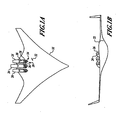
- an exemplary air induction system 20 is installed on an aircraft 22 to minimize or, in some cases, possibly eliminate the boundary layer and thereby provide intake air at an improved quality to a corresponding engine 24.
- the system 20 is adjustable to more effectively meet thrust and power requirements throughout the aircraft envelope at a variety of speeds, altitudes, and angles of attack or side-slip than the prior art.
- the aircraft 22 shown in FIGURES 1A and 1B is a blended wing-body with engines located aft, it is understood that the system 20 may be used with various configurations of any machine capable of atmospheric flight, including without limitation tube and wing aircraft, commercial transports, private airplanes, missiles, rotorcraft, or unmanned aircraft.
- the system 20 may be applied to an inlet or intake for any component(s), including not only propulsive engine 24 but also an auxiliary power unit (not shown) or environmental control system (not shown).
- the air induction system 20 includes an inlet 26 with an aperture 28 configured to receive the intake air.
- the aperture 28 may be blended into the fuselage (e.g., in a fighter aircraft), or may be in a podded nacelle spaced from the fuselage (e.g., in a commercial airliner).
- a passageway 30 extends from the aperture 28 for delivery of the air toward the engine 24.
- the inlet 26 has a longitudinal axis A, at least a portion of which is generally aligned with a direction of flow of the intake air as it approaches the inlet. For the configuration shown in FIGURE 1 , the inlet 26 is located on the aircraft 22 at a point well behind a forward, leading edge 31 of the fuselage.
- a surface 32 of the fuselage is positioned upstream of the aperture 28 such that intake air moves past the surface prior to being received by the inlet.
- a boundary layer of low-velocity air builds on the surface 32 beginning from the leading edge 31 and moves toward the inlet 26.
- the air induction system includes an exemplary control system 34.
- the control system 34 includes an arrangement of single dielectric barrier discharge generators 36 positioned along the surface 32 upstream of the aperture 28.
- the generators 36 are used as active flow control devices which reduce or eliminate ingestion of low-energy boundary layer air into the engine 24.
- the system 34 thereby increases aerodynamic performance and/or engine operational stability by improving pressure recovery and distortion, respectively.
- the system shown in each of the embodiments herein has several generators 36, there could be only a single generator or any number of generators as desired for a particular application.
- the surface 32 upstream of the aperture includes a part of the aircraft fuselage which is smooth, flat, and generally horizontal, the surface suitably may be on any component part and may be curved, stepped, rough, and/or at any orientation including vertical, as desired for a particular application.
- each generator 36 includes a pair of parallel, offset electrodes 38 and 40 separated by a dielectric barrier 42.
- the electrode 38 is exposed to the air, while the electrode 40 is covered by the dielectric 42.
- the relative positions and spacings of the electrodes 38 and 40 may vary as desired for a particular application.
- Both of the electrodes 38 and 40 are connected to a power supply 44 and a system controller 46.
- each electrode 38 and 40 is elongate in shape and can be arranged on the surface 32 either straight or with curvature.
- Each generator 36 is constructed of suitable materials that are lightweight, low cost, and readily attached to or embedded in a surface of an aircraft or inlet.
- the generator suitably is thin (such as without limitation less than about 0.1 inch) so that it does not project significantly above the surface or substantially obstruct flow of air along the surface.
- An exemplary electrode includes a strip of copper foil tape, with an exemplary dielectric comprising a strip of polyimide tape. Other arrangements and materials may be used as desired for a particular application.
- An exemplary voltage is within a range between 5 kV and 25 kV.
- the generator 36 exerts a force upon the ionized particles capable of changing the path of motion of the particles against other forces, such as inertia, which tend to maintain the particles in their normal path. That force is produced by the electric field operating on the ions in the plasma. The force acts on the air as a whole, not just the ions, because of collisions between ions and neutral particles. Thus the entire stream in proximity to the generator 36 is drawn toward the electrode 40.
- the flow is energized with increased momentum in a near-surface region, both at the electrode and, due to downstream flow propagation, for a certain distance extending downstream. Accordingly, flow separation can be delayed or prevented. If the flow has previously separated, it can be re-attached.
- the direction of the momentum which is imparted is generally aligned with an arrow B, that is, in a direction parallel with the surface and from the exposed electrode 38 toward the covered electrode 40.
- An orientation of a generator 36 is defined herein as the direction in which it imparts momentum, i.e., generally perpendicular to a length direction of the electrodes. That direction is shown by the arrows B on the various drawings.
- Each dielectric barrier discharge generator 36 advantageously remains free from a magnet, unlike some flow control devices which require a magnetic field to operate. It thereby avoids the associated weight, volume, and performance penalties of carrying a magnet or electromagnet.
- momentum is imparted to a flow of air in a direction which may not be aligned with the initial direction of flow as it approaches the inlet. That facilitates a transverse deflection of low-energy boundary layer air.
- the generators 36 are generally straight and oriented transverse to the flow (i.e., transverse to axis A) so that the applied force direction is generally perpendicular to the flow, although other, oblique angles are envisioned.
- a generator which is not aligned provides a component transverse to the flow to divert air toward a more advantageous path of motion.
- the generators 36 which are misaligned with the direction of flow tend to laterally eject the boundary layer from that stream of air which will be captured by the engine. Consequently, pressure recovery is increased and/or distortion of the intake air is reduced.
- the misalignment between the freestream flow and an underlying lateral flow component also advantageously creates vorticity and enhances mixing of the boundary layer flow.
- the result of vortex generation is a transfer of momentum to the lower portions of the boundary layer. That increases its energy to minimize negative impacts if it should be ingested by the engine.
- vortices also delay separation should the boundary layer encounter an adverse pressure gradient.
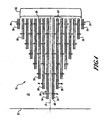
- the control system 34 includes two opposing sets 52 of generators 36 located on opposite sides of the longitudinal axis A.
- the sets 52 suitably are generally symmetric about the axis A. However, the sets 52 may be asymmetric, or there may be a single set along a single side of the axis A as desired for a particular application.
- Each set 52 has a forward generator 54, a rearward generator 56, and several intermediate generators 58 disposed generally between the generators 54 and 56.
- Each of the generators 54, 56, and 58 has a front end 60 and a back end 62.
- the relative axial position of each generator is defined herein by the axial location of its front end 60.
- the back end 62 of each generator 54, 56, and 58 is positioned slightly upstream of the front end 60 of the next successive generator.
- Each of the generators of the system 34 is generally straight and parallel to the other generators to thereby impart force and momentum in a common direction. Further, the generators form a sequence wherein each generator is spaced from the longitudinal axis A by a distance which is greater than a corresponding spacing of the generators upstream. In other words, each successive downstream generator is spaced farther from the axis A. In this way, the boundary layer is successively swept laterally outward and to a point outside of the capture region of the inlet aperture 28.
- the control system 34 substantially reduces the amount of low-energy boundary layer air from reaching the engine.
- it functions as an alternative to a supersonic "bump" inlet that diverts boundary layer laterally by blocking the flow with a large protrusion at the inlet aperture which causes formation of shock waves. Therefore, the exemplary control system 34 avoids the disadvantages of weight and volume inherent with such a bump.
- the control system 34 is effective at all speeds, unlike the bump inlet which diverts a boundary layer only at supersonic speeds. Moreover, the control system 34 does not generate shock waves, and therefore provides better pressure recovery than a bump inlet.
- an exemplary control system 70 includes generators 36 having greater length than the generators of the control system 34 ( FIGURE 2 ).
- the greater length can increase the transverse force and thereby increase the effectiveness of momentum transfer to the boundary layer.
- Each of the generators 54, 56, and 58 has its back end 62 at a common axial location with the other generators.
- an exemplary control system 80 is similar to the control system 70 ( FIGURE 4 ). However, the back ends 62 of the generators 54, 56, and 58 are positioned at different axial locations. This offers the advantage of reduced generator length and cost. Like in the control system 34 ( FIGURE 2 ), the generators positioned closer to the center of the inlet 26 have back ends which are sequentially further forward than generators spaced farther from the center. That is because it can become impractical to divert the boundary layer laterally from the center region due to insufficient distance remaining prior to the boundary layer entering the aperture 28.
- an exemplary control system 90 has generators 36 oriented at various angles.
- the forward generator 54 is transverse to the flow so that all imparted force tends to laterally divert the boundary layer.
- the successive downstream generators 58 are placed at successively shallower angles to gradually transition the direction of applied force to being parallel with the incoming flow.
- the rearward generator 56 which is located closest to the inlet aperture 28, is oriented generally parallel with the axis A (i.e., the applied momentum vectors B are parallel with the axis A). Accordingly, it accelerates flow along its existing direction to accelerate and improve the boundary layer flow prior to entering the inlet aperture 28.
- the system 90 there is a transition in the system 90 from boundary layer diversion upstream to boundary layer acceleration downstream.
- an exemplary control system 100 uses a combination of parallel and perpendicular generators 36.
- the forward , rearward, and intermediate generators 54, 56, and 58 apply force perpendicular to the flow.
- a set of one or more accelerating generators 102 applies force parallel to the flow, generally in the direction of the axis A.
- force advantageously is applied in two or more orientations.
- the generators are configured to divert the boundary layer laterally. Once a point is reached where a boundary layer can no longer be laterally diverted prior to entering the inlet, the generators are oriented such that the momentum transfer to the boundary layer accelerates air in a parallel direction.
- the generators 36 are arranged both straight and with curvature.
- Each successive intermediate generator 58 has varying curvature.
- the curvature is defined such that the force is gradually transitioned from diverting to accelerating the boundary layer.
- the outboard lateral portions of the actuators have a higher curvature, principally to continue diversion of the boundary that was initiated upstream.
- the generator(s) may take a wide variety of arrangements, orientations, numbers, sizes, and curvatures, including many which are not shown herein.
- the generator(s) may be located entirely forward of the inlet, or partially or entirely within the inlet and rearward of the inlet aperture.
- a lateral extent of the arrangement of generator(s) may be either less than or greater than a width of the inlet aperture.
- An optimum arrangement may be selected for the particular aircraft/inlet geometry and anticipated flight conditions.
- each generator 36 is controlled through system controller 46 and may be activated independently of other generators, if desired. Consequently, a designer has wide latitude in designing the controller 46 to select a combination of generator(s) for activation which will optimize performance.
- the optimum combination may vary with aircraft speed, angle-of-attack, altitude, side-slip, or engine throttle setting. For example, testing may indicate that engine performance is maximized at takeoff conditions by the activation of all generators 36, but at cruise conditions by the activation of a single generator.
- the controller 46 will activate and de-activate pre-selected combinations of generators 36 as flight conditions vary to maximize performance throughout an entire flight, including climb, maneuver, cruise, and descent.
- the generators 36 can be operated in steady state, providing a steady force to reduce or eliminate flow separation. Alternatively, the generators can be operated in a pulsed mode to minimize the required power while still reducing or eliminating flow separation.
- an exemplary control system 120 advantageously eliminates separation within an inlet 26.
- the embodiment is shown with a passageway 30 having a circular cross-section, it is understood that it may be applied to inlets with other shapes including square, "D" shapes, or non-uniform contours.
- FIGURE 11 for a discussion of shortcomings of the prior art, flow may separate from internal surfaces in the prior art, particularly when the aircraft is at a high angle of attack or sideslip angle.
- a region 122 of recirculation, or separation bubble can form inside the inlet which degrades performance in the prior art. Flow can be diverted by the bubble 122, as shown by a schematic streamline 123.
- the control system 120 includes generators 36 arranged in spaced rows 124 (see FIGURE 9 ).
- the rows 124 are annular and generally concentric in the arrangement of FIGURE 10 , although other arrangements are envisioned.
- Each row 124 includes one or more arcuate shaped segments 126.
- the rows 124 extend axially from the aperture 28 to the fan or compressor face of the engine 24.
- the generators are oriented to impart momentum generally parallel with the direction of flow and accelerate the boundary layer, as there is no need at this location to laterally eject the boundary layer.
- Each row 124 and segment 126 is independently powered, which provides for precise control of inlet distortion and recovery. By activating just the row(s) and/or segment(s) of generators which are adjacent to a region 122 of flow separation, the distortion caused by the separation can be eliminated. It is understood that the passageway 30 may have various configurations or shapes, and that rows and segments of generators may have other arrangements as desired for a particular application.
- an exemplary control system 130 advantageously eliminates separation within an inlet passageway 30, particularly for an inlet in which the flow undergoes a turn in direction.
- the inlet suitably is a "flush" inlet having an aperture 28 generally even with an adjacent surface 32.
- the flush inlet of the prior art is prone to a separation region 136 induced by large flow turning angles. Like other inlets in the prior art, it is also subject to formation of a separation region 132 induced by interaction with a shock wave 134.
- the control system 130 advantageously includes generators 36 spaced along the surfaces of the passageway 30.
- the generators extend only through a portion of the passageway length, although they may extend along the entirety of the passageway from the aperture 28 to the face of the engine 24. Complete coverage permits control of any local pockets of separation which could arise anywhere along the passageway 30.
- the generators 36 are oriented to impart momentum generally parallel with the direction of flow and accelerate the boundary layer, as there is no need at this location to laterally eject the boundary layer.
- the generators may be adapted to the cross-sectional shape of the passageway 30, i.e., straight, curved, or in rows as desired for a particular application. Each generator may be independently controlled, allowing for the precise control of distortion and recovery.
- control system of each of the various embodiments may serve as a replacement for conventional boundary layer diversion systems. Because the system is readily installed, aircraft may be retro-fit with the system while undergoing periodic maintenance. There is minimal impact to aircraft weight and volume.
- the embodiments disclosed herein advantageously may be combined partially or in entirety, such as to provide boundary layer reduction both in front of and within the interior of an inlet.
Landscapes
- Engineering & Computer Science (AREA)
- Chemical & Material Sciences (AREA)
- Combustion & Propulsion (AREA)
- Mechanical Engineering (AREA)
- General Engineering & Computer Science (AREA)
- Fluid Mechanics (AREA)
- Physics & Mathematics (AREA)
- Aviation & Aerospace Engineering (AREA)
- Plasma Technology (AREA)
- Structures Of Non-Positive Displacement Pumps (AREA)
- Jet Pumps And Other Pumps (AREA)
- Testing Of Engines (AREA)
- Electrical Discharge Machining, Electrochemical Machining, And Combined Machining (AREA)
- Control Of Positive-Displacement Air Blowers (AREA)
Claims (13)
- Luftansaugsystem (20) für ein Flugzeug (22), wobei das System aufweist:einen Einlass (26), der eine Öffnung (28) zum Aufnehmen von Ansaugluft zur Zuführung zu einem Triebwerk (24) eines Flugzeugs definiert;eine Oberfläche (32), die stromaufwärts vor der Öffnung (28) dergestalt positioniert ist, dass sich wenigstens ein Teil der Ansaugluft über die Oberfläche (32) vor der Aufnahme durch die Öffnung (28) bewegt; undein Steuerungssystem (34), das wenigstens einen ersten dielektrischen Barrierenentladungs-Generator (36) enthält, der entlang der Oberfläche (32) positioniert ist, um der Ansaugluft einen Impuls zu vermitteln; unddadurch gekennzeichnet, dassder Einlass (26) eine Längsachse (A) zur Ausrichtung im Wesentlichen in Strömungsrichtung der Ansaugluft besitzt, und wobei der dielektrische Barrierenentladungs-Generator (36) so orientiert ist, dass er nicht zu der Achse (A) ausgerichtet ist, um dadurch einen Impuls in einer Richtung mit wenigstens einer Komponente quer zr Strömungsrichtung zu vermitteln.
- System nach Anspruch 1, wobei der dielektrische Barrierenentladungs-Generator (36) ein erster Generator ist, und wobei das Steuerungssystem (34) ferner einen zweiten Generator (36) entlang der Oberfläche (32) und im Wesentlichen stromabwärts von dem ersten Generator (36) angeordnet enthält.
- System nach Anspruch 2, wobei der zweite Generator (36) im Wesentlichen parallel zu dem ersten Generator (36) ist, um dadurch einen Impuls in derselben Richtung wie der erste Generator (36) zu vermitteln.
- System nach Anspruch 3, das ferner wenigstens einen Beschleunigungsgenerator (56) stromabwärts von dem ersten Generator (36) und im Wesentlichen parallel zu der Achse orientiert aufweist.
- System nach Anspruch 2, wobei das Steuerungssystem (34) ferner wenigstens einen mit Krümmung angeordneten Generator (36) enthält.
- System nach Anspruch 2, wobei sich der zweite Generator (36) in einer nichtparallelen Orientierung zu dem ersten Generator (36) befindet.
- System nach Anspruch 6, wobei der zweite Generator (36) im Wesentlichen parallel zu der Längsachse (A) so orientiert ist, dass der zweite Generator (36) einen Impuls im Wesentlichen parallel zur Strömungsrichtung vermittelt.
- System nach Anspruch 7, wobei das Steuerungssystem (34) ferner mehrere Zwischengeneratoren (36) enthält, welche im Wesentlichen zwischen den ersten und zweiten Generatoren (36) und in zunehmend flacheren Winkeln angeordnet sind, um die Richtung der aufgebrachten Kraft umzulenken.
- Verfahren zum Steuern eines Luftansaugsystems (20) für ein Flugzeug (22), wobei das System (20) einen Einlass (26) zum Aufnehmen von Ansaugluft zur Zuführung an ein Triebwerk (24) enthält, wobei das Verfahren die Schritte aufweist:Platzieren wenigstens eines ersten dielektrischen Barrierenentladungs-Generator (36) entlang einer Oberfläche (32), die stromaufwärts vor einem Triebwerk (24) positioniert ist, so dass sich wenigstens ein Teil der Ansaugluft über die Oberfläche (32) vor seiner Zuführung an das Triebwerk (24) bewegt; undAktivieren des wenigstens einen dielektrischen Barrierenentladungs-Generators (36) mit elektrischer Energie, um der Ansaugluft einen Impuls zu vermitteln, unddadurch gekennzeichnet, dassder Einlass (26) eine Längsachse (A) zur Ausrichtung zu einer Strömungsrichtung der Ansaugluft besitzt, und wobei die Platzierung eines Generators (36) entlang der Oberfläche (32) ferner die Orientierung wenigstens eines Teils des Generators (36) in Fehlausrichtung zu der Achse (A) dergestalt beinhaltet, dass der Generator (36) einen Impuls in einer Richtung mit wenigstens einer Komponente vermittelt, welche quer zur Strömungsrichtung ist.
- Verfahren nach Anspruch 9, wobei der Einlass (26) eine Längsachse (A) zur Ausrichtung mit einer Strömungsrichtung der Ansaugluft hat, und wobei die Platzierung wenigstens eines Generators (36) entlang der Oberfläche (32) ferner die Ausrichtung des wenigstens einen Generators (36) im Wesentlichen parallel zu der Längsachse (A) dergestalt beinhaltet, dass der Generator (36) einen Impuls im Wesentlichen parallel zur Strömungsrichtung vermittelt.
- Verfahren nach Anspruch 9, wobei das System (20) mehrere dielektrische Barrierenentladungs-Generatoren (36) enthält, und ferner den Schritt der Anordnung der mehreren dielektrischen Barrierenentladungs-Generatoren (36) in Abstand entlang der Oberfläche (32) aufweist.
- Verfahren nach Anspruch 11, wobei die Anordnung eine Platzierung der Generatoren (36) in einer oder mehreren im Wesentlichen ringförmigen Reihen (124) beinhaltet.
- Verfahren nach Anspruch 9, wobei das System mehrere dielektrische Barrierenentladungs-Generatoren (36) enthält und das Verfahren ferner die Schritte aufweist:Auswählen einer ersten Kombination von Generatoren (36) zur Aktivierung bei einem ersten Flugzustand des Flugzeugs (22); undAuswählen einer sich von der ersten Kombination unterscheidenden zweiten Kombination von Generatoren (36) zum Aktivieren bei einem zweiten Flugzustand des Flugzeugs (22).
Applications Claiming Priority (2)
| Application Number | Priority Date | Filing Date | Title |
|---|---|---|---|
| US11/403,252 US7637455B2 (en) | 2006-04-12 | 2006-04-12 | Inlet distortion and recovery control system |
| PCT/US2007/006746 WO2007123612A1 (en) | 2006-04-12 | 2007-03-16 | Inlet distortion and recovery control system |
Publications (2)
| Publication Number | Publication Date |
|---|---|
| EP2010429A1 EP2010429A1 (de) | 2009-01-07 |
| EP2010429B1 true EP2010429B1 (de) | 2010-12-08 |
Family
ID=38325140
Family Applications (1)
| Application Number | Title | Priority Date | Filing Date |
|---|---|---|---|
| EP07753379A Not-in-force EP2010429B1 (de) | 2006-04-12 | 2007-03-16 | Steuersystem für einlassverzerrung und wiederherstellung |
Country Status (7)
| Country | Link |
|---|---|
| US (2) | US7637455B2 (de) |
| EP (1) | EP2010429B1 (de) |
| JP (1) | JP5265519B2 (de) |
| CN (1) | CN101421156B (de) |
| AT (1) | ATE490912T1 (de) |
| DE (1) | DE602007011047D1 (de) |
| WO (1) | WO2007123612A1 (de) |
Families Citing this family (64)
| Publication number | Priority date | Publication date | Assignee | Title |
|---|---|---|---|---|
| US8006939B2 (en) | 2006-11-22 | 2011-08-30 | Lockheed Martin Corporation | Over-wing traveling-wave axial flow plasma accelerator |
| US7870720B2 (en) * | 2006-11-29 | 2011-01-18 | Lockheed Martin Corporation | Inlet electromagnetic flow control |
| US8016246B2 (en) * | 2007-05-25 | 2011-09-13 | The Boeing Company | Plasma actuator system and method for use with a weapons bay on a high speed mobile platform |
| US7866609B2 (en) * | 2007-06-15 | 2011-01-11 | The Boeing Company | Passive removal of suction air for laminar flow control, and associated systems and methods |
| US8348626B2 (en) * | 2007-07-25 | 2013-01-08 | University Of Florida Research Foundation, Inc. | Method and apparatus for efficient micropumping |
| US8091836B2 (en) * | 2007-12-19 | 2012-01-10 | Pratt & Whitney Rocketdyne, Inc. | Rotary wing system with ion field flow control |
| US8432882B2 (en) * | 2008-01-02 | 2013-04-30 | Cisco Technology, Inc. | Multiple transport receiver |
| US8220753B2 (en) * | 2008-01-04 | 2012-07-17 | The Boeing Company | Systems and methods for controlling flows with pulsed discharges |
| US8172547B2 (en) * | 2008-01-31 | 2012-05-08 | The Boeing Company | Dielectric barrier discharge pump apparatus and method |
| ITTO20080142A1 (it) * | 2008-02-28 | 2009-08-29 | Alenia Aeronautica Spa | Presa d'aria, in particolare per un espulsore di chaff per velivolo |
| DE102008001103A1 (de) * | 2008-04-10 | 2009-10-15 | Manroland Ag | Umströmtes Bauteil |
| US9446840B2 (en) * | 2008-07-01 | 2016-09-20 | The Boeing Company | Systems and methods for alleviating aircraft loads with plasma actuators |
| EP2321084B1 (de) * | 2008-07-31 | 2017-03-22 | Bell Helicopter Textron Inc. | System und verfahren für aerodynamische flusssteuerung |
| US8196871B2 (en) * | 2008-11-26 | 2012-06-12 | General Electric Company | Control of shockwave-boundarylayer-interaction using MEMS plasma devices |
| US8226047B2 (en) * | 2009-01-23 | 2012-07-24 | General Electric Company | Reduction of tip vortex and wake interaction effects in energy and propulsion systems |
| US8941291B2 (en) | 2009-08-26 | 2015-01-27 | Daihatsu Motor Co., Ltd. | Plasma actuator |
| US8453457B2 (en) * | 2009-08-26 | 2013-06-04 | Lockheed Martin Corporation | Nozzle plasma flow control utilizing dielectric barrier discharge plasma actuators |
| US9975625B2 (en) | 2010-04-19 | 2018-05-22 | The Boeing Company | Laminated plasma actuator |
| FR2959342B1 (fr) * | 2010-04-27 | 2012-06-15 | Snecma | Procede de traitement des ondes acoustiques emises en sortie d'un turbomoteur d'un aeronef avec un dispositif a decharge a barriere dielectrique et aeronef comprenant un tel dispositif |
| US8523115B2 (en) | 2011-01-28 | 2013-09-03 | Lockheed Martin Corporation | System, apparatus, program product, and related methods for providing boundary layer flow control |
| US8944370B2 (en) * | 2012-01-09 | 2015-02-03 | The Boeing Company | Plasma actuating propulsion system for aerial vehicles |
| US20130312385A1 (en) * | 2012-05-24 | 2013-11-28 | General Electric Company | Gas turbine system having a plasma actuator flow control arrangement |
| US20140119879A1 (en) * | 2012-10-29 | 2014-05-01 | General Electric Company | Turbomachine plasma seal system |
| WO2014084925A1 (en) * | 2012-11-27 | 2014-06-05 | The Board Of Regents Of The University Of Texas System | Rail plasma actuator for high-authority flow control |
| DE102013200470A1 (de) * | 2013-01-15 | 2014-07-17 | Siemens Aktiengesellschaft | Verfahren zur Steuerung eines Gasmassenstroms, Strömungskanal sowie Turbomaschine mit Strömungskanal |
| US9884688B2 (en) * | 2013-02-14 | 2018-02-06 | Gulfstream Aerospace Corporation | Propulsion system using large scale vortex generators for flow redistribution and supersonic aircraft equipped with the propulsion system |
| US9820369B2 (en) | 2013-02-25 | 2017-11-14 | University Of Florida Research Foundation, Incorporated | Method and apparatus for providing high control authority atmospheric plasma |
| US20160122005A1 (en) * | 2013-03-11 | 2016-05-05 | United Technologies Corporation | Embedded engines in hybrid blended wing body |
| US9359950B2 (en) | 2013-05-20 | 2016-06-07 | Honeywell International Inc. | Gas turbine engines having plasma flow-controlled intake systems |
| CN104443404A (zh) * | 2014-11-24 | 2015-03-25 | 江西洪都航空工业集团有限责任公司 | 一种飞行器的s形进气道结构 |
| EP3090952B1 (de) * | 2015-03-31 | 2018-10-03 | Rolls-Royce Corporation | Triebwerksgondel |
| US9758253B2 (en) | 2015-06-25 | 2017-09-12 | Northrop Grumman Systems Corporation | Swept gradient boundary layer diverter |
| EP3162713B1 (de) * | 2015-10-30 | 2018-08-01 | Sikorsky Aircraft Corporation | Leistungsausgleichssteuergerät |
| US10794281B2 (en) * | 2016-02-02 | 2020-10-06 | General Electric Company | Gas turbine engine having instrumented airflow path components |
| US11073090B2 (en) | 2016-03-30 | 2021-07-27 | General Electric Company | Valved airflow passage assembly for adjusting airflow distortion in gas turbine engine |
| US9777633B1 (en) | 2016-03-30 | 2017-10-03 | General Electric Company | Secondary airflow passage for adjusting airflow distortion in gas turbine engine |
| US10753278B2 (en) | 2016-03-30 | 2020-08-25 | General Electric Company | Translating inlet for adjusting airflow distortion in gas turbine engine |
| US10704418B2 (en) | 2016-08-11 | 2020-07-07 | General Electric Company | Inlet assembly for an aircraft aft fan |
| US10399670B2 (en) * | 2016-09-26 | 2019-09-03 | General Electric Company | Aircraft having an aft engine and internal flow passages |
| US20180208297A1 (en) | 2017-01-20 | 2018-07-26 | General Electric Company | Nacelle for an aircraft aft fan |
| US10837362B2 (en) | 2016-10-12 | 2020-11-17 | General Electric Company | Inlet cowl for a turbine engine |
| US11149639B2 (en) * | 2016-11-29 | 2021-10-19 | Rolls-Royce North American Technologies Inc. | Systems and methods of reducing distortions of the inlet airflow to a turbomachine |
| US10549845B2 (en) * | 2017-05-26 | 2020-02-04 | United Technologies Corporation | Dedicated fans for boundary layer ingestion |
| GB201716836D0 (en) * | 2017-10-13 | 2017-11-29 | Rolls Royce Plc | Gas turbine engine vortex suppressor |
| US10495121B2 (en) * | 2017-11-10 | 2019-12-03 | X Development Llc | Method and apparatus for combined anemometer and plasma actuator |
| KR101860686B1 (ko) | 2017-11-13 | 2018-06-29 | 국방과학연구소 | 플라즈마 구동기 보호 장치 및 이의 조립 방법 |
| CN109159903A (zh) * | 2018-08-23 | 2019-01-08 | 广州创链科技有限公司 | 一种无人机发动机进行口气流调节装置 |
| US11125770B2 (en) * | 2018-12-06 | 2021-09-21 | Rosemount Aerospace Inc. | Acoustic air data sensor and system |
| WO2020247031A1 (en) * | 2019-06-07 | 2020-12-10 | Massachusetts Institute Of Technology | Electroaerodynamic devices |
| US11905983B2 (en) * | 2020-01-23 | 2024-02-20 | Deep Science, Llc | Systems and methods for active control of surface drag using electrodes |
| WO2021150755A1 (en) | 2020-01-23 | 2021-07-29 | Deep Science, Llc | Systems and methods for active control of surface drag using intermittent or variable actuation |
| CN113567141B (zh) * | 2020-04-28 | 2024-02-02 | 中国航发商用航空发动机有限责任公司 | 畸变发生装置及其模拟方法和压力畸变特性试验系统 |
| US11333079B2 (en) * | 2020-04-28 | 2022-05-17 | General Electric Company | Methods and apparatus to detect air flow separation of an engine |
| US11542866B2 (en) * | 2020-05-13 | 2023-01-03 | The Boeing Company | Adaptable flow control for engine nacelles |
| US11466709B2 (en) | 2021-02-17 | 2022-10-11 | Deep Science, Llc | In-plane transverse momentum injection to disrupt large-scale eddies in a turbulent boundary layer |
| US12071224B2 (en) | 2021-11-30 | 2024-08-27 | The Boeing Company | Aircraft boundary layer ingestion using multiple fans and associated methods |
| CN114194402B (zh) * | 2021-12-16 | 2024-05-31 | 重庆交通大学绿色航空技术研究院 | 等离子体激励的无附面隔层进气道系统及进气控制方法 |
| US12065979B2 (en) | 2022-12-27 | 2024-08-20 | Rolls-Royce North American Technologies Inc. | Distributed electric and hybrid fans for distortion tolerance of turbofan engines |
| US12025059B1 (en) | 2022-12-27 | 2024-07-02 | Rolls-Royce North American Technologies Inc. | Distributed electric tip fans for distortion tolerance of turbofan engines |
| US11835064B1 (en) | 2022-12-27 | 2023-12-05 | Rolls-Royce North American Technologies Inc. | Electric fan array for distortion tolerance of turbofan engines |
| US12065258B2 (en) * | 2023-01-25 | 2024-08-20 | Rolls-Royce North American Technologies Inc. | Multiple intake distortion adaptive fan for gas turbine engine |
| US12545422B2 (en) | 2023-01-26 | 2026-02-10 | The Boeing Company | Variable compression air intakes for aircraft propulsion systems and methods for varying compression of an air intake |
| US12503978B1 (en) | 2024-06-21 | 2025-12-23 | Rolls-Royce North American Technologies Inc. | Inlets for gas turbine engine fans with distortion tolerance |
| CN118395906B (zh) * | 2024-06-28 | 2024-09-27 | 中国航发湖南动力机械研究所 | 进气畸变试验中温度畸变与压力畸变的等效转换方法及系统 |
Family Cites Families (25)
| Publication number | Priority date | Publication date | Assignee | Title |
|---|---|---|---|---|
| US2694357A (en) * | 1950-07-18 | 1954-11-16 | Chance Vought Aircraft Inc | Boundary layer energization for flush inlets |
| US3360220A (en) * | 1959-01-26 | 1967-12-26 | Space Technology Lab Inc | Magnetohydrodynamic method and apparatus |
| US3041827A (en) * | 1959-02-25 | 1962-07-03 | Curtiss Wright Corp | Supersonic inlet |
| GB1119701A (en) * | 1964-08-13 | 1968-07-10 | Bristol Siddeley Engines Ltd | Guards for air intakes of jet engines |
| US4154256A (en) * | 1978-03-29 | 1979-05-15 | The United States Of America As Represented By The Administrator Of The National Aeronautics And Space Administration | Self stabilizing sonic inlet |
| US4891600A (en) * | 1982-07-26 | 1990-01-02 | Cox James E | Dipole accelerating means and method |
| DE3407137A1 (de) | 1984-02-28 | 1985-08-29 | Messerschmitt-Bölkow-Blohm GmbH, 8012 Ottobrunn | Einrichtung zur verbesserung der stroemungsverhaeltnisse am lufteinlauf fuer in flugzeugen eingebaute gasturbinentriebwerke |
| US4696442A (en) * | 1986-07-14 | 1987-09-29 | The Boeing Company | Vortex generators for inlets |
| US5058837A (en) * | 1989-04-07 | 1991-10-22 | Wheeler Gary O | Low drag vortex generators |
| US5447283A (en) * | 1994-02-02 | 1995-09-05 | Grumman Aerospace Corporation | Blown boundary layer control system for a jet aircraft |
| US5598990A (en) * | 1994-12-15 | 1997-02-04 | University Of Kansas Center For Research Inc. | Supersonic vortex generator |
| US5779189A (en) | 1996-03-19 | 1998-07-14 | Lockheed Martin Corporation | System and method for diverting boundary layer air |
| US5749542A (en) | 1996-05-28 | 1998-05-12 | Lockheed Martin Corporation | Transition shoulder system and method for diverting boundary layer air |
| AU3180099A (en) | 1998-01-08 | 1999-07-26 | Government of the United States of America as represented by the Administrator of the National Aeronautics and Space Administration (NASA), The | Paraelectric gas flow accelerator |
| US6138950A (en) * | 1998-10-06 | 2000-10-31 | Northrop Grumman Corporation | Aircraft engine air intake system |
| US6504308B1 (en) * | 1998-10-16 | 2003-01-07 | Kronos Air Technologies, Inc. | Electrostatic fluid accelerator |
| US20020134891A1 (en) * | 2001-02-09 | 2002-09-26 | Guillot Stephen A. | Ejector pump flow control |
| GB0108740D0 (en) | 2001-04-06 | 2001-05-30 | Bae Systems Plc | Turbulent flow drag reduction |
| US6570333B1 (en) | 2002-01-31 | 2003-05-27 | Sandia Corporation | Method for generating surface plasma |
| US20040011917A1 (en) | 2002-07-18 | 2004-01-22 | Saeks Richard E. | Shock wave modification via shock induced ion doping |
| US6796532B2 (en) | 2002-12-20 | 2004-09-28 | Norman D. Malmuth | Surface plasma discharge for controlling forebody vortex asymmetry |
| US6805325B1 (en) | 2003-04-03 | 2004-10-19 | Rockwell Scientific Licensing, Llc. | Surface plasma discharge for controlling leading edge contamination and crossflow instabilities for laminar flow |
| US7380756B1 (en) * | 2003-11-17 | 2008-06-03 | The United States Of America As Represented By The Secretary Of The Air Force | Single dielectric barrier aerodynamic plasma actuation |
| US7510149B2 (en) * | 2004-08-02 | 2009-03-31 | Lockheed Martin Corporation | System and method to control flowfield vortices with micro-jet arrays |
| US7744039B2 (en) * | 2006-01-03 | 2010-06-29 | The Boeing Company | Systems and methods for controlling flows with electrical pulses |
-
2006
- 2006-04-12 US US11/403,252 patent/US7637455B2/en not_active Expired - Fee Related
-
2007
- 2007-03-16 WO PCT/US2007/006746 patent/WO2007123612A1/en not_active Ceased
- 2007-03-16 AT AT07753379T patent/ATE490912T1/de not_active IP Right Cessation
- 2007-03-16 EP EP07753379A patent/EP2010429B1/de not_active Not-in-force
- 2007-03-16 DE DE602007011047T patent/DE602007011047D1/de active Active
- 2007-03-16 CN CN2007800132808A patent/CN101421156B/zh not_active Expired - Fee Related
- 2007-03-16 JP JP2009505369A patent/JP5265519B2/ja not_active Expired - Fee Related
-
2009
- 2009-11-16 US US12/619,028 patent/US7975961B2/en not_active Expired - Fee Related
Also Published As
| Publication number | Publication date |
|---|---|
| US20070241229A1 (en) | 2007-10-18 |
| US7637455B2 (en) | 2009-12-29 |
| JP2009533276A (ja) | 2009-09-17 |
| US7975961B2 (en) | 2011-07-12 |
| EP2010429A1 (de) | 2009-01-07 |
| DE602007011047D1 (de) | 2011-01-20 |
| WO2007123612A1 (en) | 2007-11-01 |
| CN101421156A (zh) | 2009-04-29 |
| JP5265519B2 (ja) | 2013-08-14 |
| CN101421156B (zh) | 2011-05-25 |
| ATE490912T1 (de) | 2010-12-15 |
| US20100140418A1 (en) | 2010-06-10 |
Similar Documents
| Publication | Publication Date | Title |
|---|---|---|
| EP2010429B1 (de) | Steuersystem für einlassverzerrung und wiederherstellung | |
| US11987352B2 (en) | Fluid systems that include a co-flow jet | |
| JP6930743B2 (ja) | エジェクタ及びエアフォイル形状 | |
| EP2511175B1 (de) | Vorrichtung und Verfahren zur Lärm- und Wirbelminderung von Flugzeugen | |
| EP2219942B2 (de) | Systeme und verfahren zur steuerung von motorabgasströmung | |
| CN101952170B (zh) | 用于飞行器前缘的空气出口系统 | |
| US11053012B2 (en) | Winglet ejector configurations | |
| US9587585B1 (en) | Augmented propulsion system with boundary layer suction and wake blowing | |
| EP3112650B1 (de) | Einlassdurchflussbegrenzer | |
| US5490644A (en) | Ducted boundary layer diverter | |
| CN113120218A (zh) | 用于高亚音机翼流动分离控制的复合等离子体激励方法 | |
| CN103038132A (zh) | 驱动的飞行器、尤其构造为全翼飞机并且/或者带有较小的雷达讯号的飞行器 | |
| US9046035B2 (en) | Compression ramp boundary layer removal | |
| WO2026057092A1 (zh) | 一种固定翼飞机 | |
| RU2094307C1 (ru) | Транспортный самолет с затупленной хвостовой частью фюзеляжа | |
| RU2425241C2 (ru) | Реактивное сопло с ориентацией тяги, способ его функционирования, турбореактивный двигатель и беспилотный летательный аппарат, оборудованный таким соплом | |
| IL271437B2 (en) | Pinion outlet configuration | |
| US20240336350A1 (en) | A system for lift, propulsion and control of an airborne craft |
Legal Events
| Date | Code | Title | Description |
|---|---|---|---|
| PUAI | Public reference made under article 153(3) epc to a published international application that has entered the european phase |
Free format text: ORIGINAL CODE: 0009012 |
|
| 17P | Request for examination filed |
Effective date: 20081112 |
|
| AK | Designated contracting states |
Kind code of ref document: A1 Designated state(s): AT BE BG CH CY CZ DE DK EE ES FI FR GB GR HU IE IS IT LI LT LU LV MC MT NL PL PT RO SE SI SK TR |
|
| AX | Request for extension of the european patent |
Extension state: AL BA HR MK RS |
|
| 17Q | First examination report despatched |
Effective date: 20090728 |
|
| GRAP | Despatch of communication of intention to grant a patent |
Free format text: ORIGINAL CODE: EPIDOSNIGR1 |
|
| GRAS | Grant fee paid |
Free format text: ORIGINAL CODE: EPIDOSNIGR3 |
|
| GRAA | (expected) grant |
Free format text: ORIGINAL CODE: 0009210 |
|
| AK | Designated contracting states |
Kind code of ref document: B1 Designated state(s): AT BE BG CH CY CZ DE DK EE ES FI FR GB GR HU IE IS IT LI LT LU LV MC MT NL PL PT RO SE SI SK TR |
|
| REG | Reference to a national code |
Ref country code: GB Ref legal event code: FG4D |
|
| REG | Reference to a national code |
Ref country code: CH Ref legal event code: EP |
|
| REG | Reference to a national code |
Ref country code: IE Ref legal event code: FG4D |
|
| REF | Corresponds to: |
Ref document number: 602007011047 Country of ref document: DE Date of ref document: 20110120 Kind code of ref document: P |
|
| REG | Reference to a national code |
Ref country code: NL Ref legal event code: VDEP Effective date: 20101208 |
|
| PG25 | Lapsed in a contracting state [announced via postgrant information from national office to epo] |
Ref country code: LT Free format text: LAPSE BECAUSE OF FAILURE TO SUBMIT A TRANSLATION OF THE DESCRIPTION OR TO PAY THE FEE WITHIN THE PRESCRIBED TIME-LIMIT Effective date: 20101208 |
|
| LTIE | Lt: invalidation of european patent or patent extension |
Effective date: 20101208 |
|
| PG25 | Lapsed in a contracting state [announced via postgrant information from national office to epo] |
Ref country code: NL Free format text: LAPSE BECAUSE OF FAILURE TO SUBMIT A TRANSLATION OF THE DESCRIPTION OR TO PAY THE FEE WITHIN THE PRESCRIBED TIME-LIMIT Effective date: 20101208 Ref country code: CY Free format text: LAPSE BECAUSE OF FAILURE TO SUBMIT A TRANSLATION OF THE DESCRIPTION OR TO PAY THE FEE WITHIN THE PRESCRIBED TIME-LIMIT Effective date: 20101208 Ref country code: FI Free format text: LAPSE BECAUSE OF FAILURE TO SUBMIT A TRANSLATION OF THE DESCRIPTION OR TO PAY THE FEE WITHIN THE PRESCRIBED TIME-LIMIT Effective date: 20101208 Ref country code: AT Free format text: LAPSE BECAUSE OF FAILURE TO SUBMIT A TRANSLATION OF THE DESCRIPTION OR TO PAY THE FEE WITHIN THE PRESCRIBED TIME-LIMIT Effective date: 20101208 Ref country code: BG Free format text: LAPSE BECAUSE OF FAILURE TO SUBMIT A TRANSLATION OF THE DESCRIPTION OR TO PAY THE FEE WITHIN THE PRESCRIBED TIME-LIMIT Effective date: 20110308 Ref country code: LV Free format text: LAPSE BECAUSE OF FAILURE TO SUBMIT A TRANSLATION OF THE DESCRIPTION OR TO PAY THE FEE WITHIN THE PRESCRIBED TIME-LIMIT Effective date: 20101208 Ref country code: SE Free format text: LAPSE BECAUSE OF FAILURE TO SUBMIT A TRANSLATION OF THE DESCRIPTION OR TO PAY THE FEE WITHIN THE PRESCRIBED TIME-LIMIT Effective date: 20101208 Ref country code: SI Free format text: LAPSE BECAUSE OF FAILURE TO SUBMIT A TRANSLATION OF THE DESCRIPTION OR TO PAY THE FEE WITHIN THE PRESCRIBED TIME-LIMIT Effective date: 20101208 |
|
| PG25 | Lapsed in a contracting state [announced via postgrant information from national office to epo] |
Ref country code: ES Free format text: LAPSE BECAUSE OF FAILURE TO SUBMIT A TRANSLATION OF THE DESCRIPTION OR TO PAY THE FEE WITHIN THE PRESCRIBED TIME-LIMIT Effective date: 20110319 Ref country code: IS Free format text: LAPSE BECAUSE OF FAILURE TO SUBMIT A TRANSLATION OF THE DESCRIPTION OR TO PAY THE FEE WITHIN THE PRESCRIBED TIME-LIMIT Effective date: 20110408 Ref country code: PT Free format text: LAPSE BECAUSE OF FAILURE TO SUBMIT A TRANSLATION OF THE DESCRIPTION OR TO PAY THE FEE WITHIN THE PRESCRIBED TIME-LIMIT Effective date: 20110408 Ref country code: CZ Free format text: LAPSE BECAUSE OF FAILURE TO SUBMIT A TRANSLATION OF THE DESCRIPTION OR TO PAY THE FEE WITHIN THE PRESCRIBED TIME-LIMIT Effective date: 20101208 Ref country code: EE Free format text: LAPSE BECAUSE OF FAILURE TO SUBMIT A TRANSLATION OF THE DESCRIPTION OR TO PAY THE FEE WITHIN THE PRESCRIBED TIME-LIMIT Effective date: 20101208 Ref country code: GR Free format text: LAPSE BECAUSE OF FAILURE TO SUBMIT A TRANSLATION OF THE DESCRIPTION OR TO PAY THE FEE WITHIN THE PRESCRIBED TIME-LIMIT Effective date: 20110309 Ref country code: BE Free format text: LAPSE BECAUSE OF FAILURE TO SUBMIT A TRANSLATION OF THE DESCRIPTION OR TO PAY THE FEE WITHIN THE PRESCRIBED TIME-LIMIT Effective date: 20101208 |
|
| PG25 | Lapsed in a contracting state [announced via postgrant information from national office to epo] |
Ref country code: SK Free format text: LAPSE BECAUSE OF FAILURE TO SUBMIT A TRANSLATION OF THE DESCRIPTION OR TO PAY THE FEE WITHIN THE PRESCRIBED TIME-LIMIT Effective date: 20101208 Ref country code: RO Free format text: LAPSE BECAUSE OF FAILURE TO SUBMIT A TRANSLATION OF THE DESCRIPTION OR TO PAY THE FEE WITHIN THE PRESCRIBED TIME-LIMIT Effective date: 20101208 Ref country code: PL Free format text: LAPSE BECAUSE OF FAILURE TO SUBMIT A TRANSLATION OF THE DESCRIPTION OR TO PAY THE FEE WITHIN THE PRESCRIBED TIME-LIMIT Effective date: 20101208 |
|
| PLBE | No opposition filed within time limit |
Free format text: ORIGINAL CODE: 0009261 |
|
| STAA | Information on the status of an ep patent application or granted ep patent |
Free format text: STATUS: NO OPPOSITION FILED WITHIN TIME LIMIT |
|
| PG25 | Lapsed in a contracting state [announced via postgrant information from national office to epo] |
Ref country code: MC Free format text: LAPSE BECAUSE OF NON-PAYMENT OF DUE FEES Effective date: 20110331 Ref country code: DK Free format text: LAPSE BECAUSE OF FAILURE TO SUBMIT A TRANSLATION OF THE DESCRIPTION OR TO PAY THE FEE WITHIN THE PRESCRIBED TIME-LIMIT Effective date: 20101208 |
|
| REG | Reference to a national code |
Ref country code: CH Ref legal event code: PL |
|
| 26N | No opposition filed |
Effective date: 20110909 |
|
| PG25 | Lapsed in a contracting state [announced via postgrant information from national office to epo] |
Ref country code: IT Free format text: LAPSE BECAUSE OF FAILURE TO SUBMIT A TRANSLATION OF THE DESCRIPTION OR TO PAY THE FEE WITHIN THE PRESCRIBED TIME-LIMIT Effective date: 20101208 Ref country code: MT Free format text: LAPSE BECAUSE OF FAILURE TO SUBMIT A TRANSLATION OF THE DESCRIPTION OR TO PAY THE FEE WITHIN THE PRESCRIBED TIME-LIMIT Effective date: 20101208 |
|
| REG | Reference to a national code |
Ref country code: IE Ref legal event code: MM4A |
|
| REG | Reference to a national code |
Ref country code: DE Ref legal event code: R097 Ref document number: 602007011047 Country of ref document: DE Effective date: 20110909 |
|
| PG25 | Lapsed in a contracting state [announced via postgrant information from national office to epo] |
Ref country code: LI Free format text: LAPSE BECAUSE OF NON-PAYMENT OF DUE FEES Effective date: 20110331 Ref country code: IE Free format text: LAPSE BECAUSE OF NON-PAYMENT OF DUE FEES Effective date: 20110316 Ref country code: CH Free format text: LAPSE BECAUSE OF NON-PAYMENT OF DUE FEES Effective date: 20110331 |
|
| PG25 | Lapsed in a contracting state [announced via postgrant information from national office to epo] |
Ref country code: LU Free format text: LAPSE BECAUSE OF NON-PAYMENT OF DUE FEES Effective date: 20110316 |
|
| PG25 | Lapsed in a contracting state [announced via postgrant information from national office to epo] |
Ref country code: TR Free format text: LAPSE BECAUSE OF FAILURE TO SUBMIT A TRANSLATION OF THE DESCRIPTION OR TO PAY THE FEE WITHIN THE PRESCRIBED TIME-LIMIT Effective date: 20101208 |
|
| PG25 | Lapsed in a contracting state [announced via postgrant information from national office to epo] |
Ref country code: HU Free format text: LAPSE BECAUSE OF FAILURE TO SUBMIT A TRANSLATION OF THE DESCRIPTION OR TO PAY THE FEE WITHIN THE PRESCRIBED TIME-LIMIT Effective date: 20101208 |
|
| REG | Reference to a national code |
Ref country code: FR Ref legal event code: PLFP Year of fee payment: 10 |
|
| REG | Reference to a national code |
Ref country code: FR Ref legal event code: PLFP Year of fee payment: 11 |
|
| REG | Reference to a national code |
Ref country code: DE Ref legal event code: R082 Ref document number: 602007011047 Country of ref document: DE Representative=s name: BRINKMANN & PARTNER PATENTANWAELTE PARTNERSCHA, DE Ref country code: DE Ref legal event code: R082 Ref document number: 602007011047 Country of ref document: DE Representative=s name: RAUSCH WANISCHECK-BERGMANN BRINKMANN PARTNERSC, DE |
|
| REG | Reference to a national code |
Ref country code: FR Ref legal event code: PLFP Year of fee payment: 12 |
|
| PGFP | Annual fee paid to national office [announced via postgrant information from national office to epo] |
Ref country code: DE Payment date: 20200327 Year of fee payment: 14 Ref country code: GB Payment date: 20200327 Year of fee payment: 14 |
|
| PGFP | Annual fee paid to national office [announced via postgrant information from national office to epo] |
Ref country code: FR Payment date: 20200325 Year of fee payment: 14 |
|
| REG | Reference to a national code |
Ref country code: DE Ref legal event code: R119 Ref document number: 602007011047 Country of ref document: DE |
|
| GBPC | Gb: european patent ceased through non-payment of renewal fee |
Effective date: 20210316 |
|
| PG25 | Lapsed in a contracting state [announced via postgrant information from national office to epo] |
Ref country code: DE Free format text: LAPSE BECAUSE OF NON-PAYMENT OF DUE FEES Effective date: 20211001 Ref country code: GB Free format text: LAPSE BECAUSE OF NON-PAYMENT OF DUE FEES Effective date: 20210316 Ref country code: FR Free format text: LAPSE BECAUSE OF NON-PAYMENT OF DUE FEES Effective date: 20210331 |