EP2009519A2 - Timepiece - Google Patents
Timepiece Download PDFInfo
- Publication number
- EP2009519A2 EP2009519A2 EP08011519A EP08011519A EP2009519A2 EP 2009519 A2 EP2009519 A2 EP 2009519A2 EP 08011519 A EP08011519 A EP 08011519A EP 08011519 A EP08011519 A EP 08011519A EP 2009519 A2 EP2009519 A2 EP 2009519A2
- Authority
- EP
- European Patent Office
- Prior art keywords
- glass
- back cover
- retainer ring
- timepiece
- disposed
- Prior art date
- Legal status (The legal status is an assumption and is not a legal conclusion. Google has not performed a legal analysis and makes no representation as to the accuracy of the status listed.)
- Withdrawn
Links
- 239000011521 glass Substances 0.000 claims abstract description 293
- 239000013078 crystal Substances 0.000 claims abstract description 36
- 239000002184 metal Substances 0.000 claims description 110
- 229910052751 metal Inorganic materials 0.000 claims description 110
- 238000012856 packing Methods 0.000 claims description 98
- 230000035939 shock Effects 0.000 claims description 35
- 239000007769 metal material Substances 0.000 claims description 2
- 230000035945 sensitivity Effects 0.000 description 22
- 210000004247 hand Anatomy 0.000 description 14
- XLYOFNOQVPJJNP-UHFFFAOYSA-N water Substances O XLYOFNOQVPJJNP-UHFFFAOYSA-N 0.000 description 12
- 239000004033 plastic Substances 0.000 description 11
- 239000006096 absorbing agent Substances 0.000 description 10
- 239000000853 adhesive Substances 0.000 description 9
- 230000001070 adhesive effect Effects 0.000 description 9
- 239000013013 elastic material Substances 0.000 description 8
- 239000000696 magnetic material Substances 0.000 description 8
- 238000009877 rendering Methods 0.000 description 8
- 239000000463 material Substances 0.000 description 7
- 238000013461 design Methods 0.000 description 6
- 230000005489 elastic deformation Effects 0.000 description 5
- 238000000034 method Methods 0.000 description 5
- 210000000707 wrist Anatomy 0.000 description 5
- 230000000694 effects Effects 0.000 description 3
- 239000004973 liquid crystal related substance Substances 0.000 description 3
- 238000010276 construction Methods 0.000 description 2
- 230000002452 interceptive effect Effects 0.000 description 2
- 239000005355 lead glass Substances 0.000 description 2
- 229910052594 sapphire Inorganic materials 0.000 description 2
- 239000010980 sapphire Substances 0.000 description 2
- RTAQQCXQSZGOHL-UHFFFAOYSA-N Titanium Chemical compound [Ti] RTAQQCXQSZGOHL-UHFFFAOYSA-N 0.000 description 1
- 230000001771 impaired effect Effects 0.000 description 1
- 238000012423 maintenance Methods 0.000 description 1
- 238000012545 processing Methods 0.000 description 1
- 239000010453 quartz Substances 0.000 description 1
- 239000011359 shock absorbing material Substances 0.000 description 1
- VYPSYNLAJGMNEJ-UHFFFAOYSA-N silicon dioxide Inorganic materials O=[Si]=O VYPSYNLAJGMNEJ-UHFFFAOYSA-N 0.000 description 1
- 239000010936 titanium Substances 0.000 description 1
- 229910052719 titanium Inorganic materials 0.000 description 1
Images





Classifications
-
- G—PHYSICS
- G04—HOROLOGY
- G04G—ELECTRONIC TIME-PIECES
- G04G21/00—Input or output devices integrated in time-pieces
- G04G21/04—Input or output devices integrated in time-pieces using radio waves
-
- G—PHYSICS
- G04—HOROLOGY
- G04G—ELECTRONIC TIME-PIECES
- G04G17/00—Structural details; Housings
- G04G17/08—Housings
-
- G—PHYSICS
- G04—HOROLOGY
- G04R—RADIO-CONTROLLED TIME-PIECES
- G04R60/00—Constructional details
- G04R60/06—Antennas attached to or integrated in clock or watch bodies
- G04R60/10—Antennas attached to or integrated in clock or watch bodies inside cases
- G04R60/12—Antennas attached to or integrated in clock or watch bodies inside cases inside metal cases
Definitions
- the present invention relates to a timepiece with a built-in antenna.
- Japanese Unexamined Patent Appl. Pub. JP-A-2006-275580 and Japanese Unexamined Patent Appl. Pub. JP-A-02-116784 teach so-called radio-controlled timepieces that set the time based on time information contained in a received standard time signal.
- the radio-controlled timepiece taught in Japanese Unexamined Patent Appl. Pub. JP-A-2006-275580 has a timepiece case that is a substantially annular metal member, a crystal that is attached with an intervening packing member to the top of the timepiece case, a back cover that is made of metal and attached to the bottom of the timepiece case, and a movement including a radio-controlled timepiece receiver that is disposed inside the timepiece case.
- Ahollow is rendered in the inside surface and back cover of the timepiece case in this radio-controlled timepiece,and an arrangement ofengaged non-magnetic members with electrical resistivity of 7.00 ⁇ or less is disposed in this hollow.
- Japanese Unexamined Patent Appl. Pub. JP-A-02-116784 teaches a skeleton timepiece that renders a housing area in an annular case, and attaches a face crystal and a back cover to the sealed portions of the case.
- Disposing non-magnetic parts in a part of the radio-controlled timepiece renders an arrangement that reduces disruption of resonance near the receiver part of the radio-controlled timepiece, but sufficient reception sensitivity cannot be achieved because the timepiece case and back cover are metal.
- a problem with the skeleton timepiece such as taught in Japanese Unexamined Patent Appl. Pub. JP-A-02-116784 is that when the case is made of glass and a hole for inserting the crown is formed in the case, the hole greatly reduces the durability of the case.
- a timepiece according to the present invention achieves both good reception sensitivity and durability.
- a first aspect of the invention is a timepiece having: a retainer ring including a timepiece crystal and a glass retaining unit that holds the outside edge of the crystal; a back cover that is disposed facing the retainer ring; a case member that is substantially annular, is made at least in part from a non-magnetic member, and links the outside edges of the retainer ring and the back cover; an antenna that is disposed in a space formed between the retainer ring and the back cover, and can receive radio signals that pass through the non-magnetic member of the case member to the inside of the case member; and a timekeeping unit that is disposed in a space formed between the retainer ring and the back cover, and has a time display unit for displaying the time.
- At least part of the case member that connects the outside edges of the retainer ring and back cover is formed by a non-magnetic member in a timepiece according to this aspect of the invention.
- An antenna that can receive predetermined radio signals (external wireless information) is disposed in the space between the retainer ring and the back cover, or more particularly inside the case rendered by the retainer ring, the back cover, and the case member.
- radio frequency signals can pass through the non-magnetic part of the side of the timepiece, can be received by the antenna with good signal strength, and reception sensitivity can thus be improved.
- the reception sensitivity of the antenna can be improved compared with a wristwatch that has a back cover made of glass or other non-magnetic member and a metal case member. More specifically, when GPS signals, for example, are the received radio frequency signals in a timepiece that has a back cover made of glass or other non-magnetic material, the GPS signal reception sensitivity is reduced when the back cover is in contact with the skin when the wristwatch is worn on the wrist. The reception sensitivity of the antenna also drops when the wristwatch band is metal and the wristwatch is removed from the wrist and placed with the metal band near the back cover.
- radio frequency signals received by the antenna include standard time signals carrying time information, GPS signals, and cell phone signals, and the correct time can be displayed by adjusting the time displayed on the time display unit (the movement of an analog timepiece or the timekeeping module of a digital timepiece) of the timekeeping unit (the hands and dial of an analog timepiece, or the liquid crystal display or organic electroluminescent display of a digital timepiece) based on the time information decoded from the received signal.
- the RF signals can pass into the case from the side of the time piece case (case member) , signals can be received by the antenna even if the dial or back cover is metal.
- a metal dial which is conventionally difficult to use in a radio-controlled timepiece, can therefore be used in a radio-controlled timepiece, and the design of the dial can be improved.
- the non-magnetic member of the case member is formed in a ring around the circumference of the case member.
- the non-magnetic member in this aspect of the invention is formed in a ring around the circumference of the case member. Compared with an arrangement in which the non-magnetic member is formed in a C-shape circumferentially to the case member, rendering the non-magnetic member as a closed ring improves the radial durability and strength and provides greater protection against damage caused by impact.
- radio signals can pass through the non-magnetic member from any direction, and the reception sensitivity of the antenna can be improved.
- the case member is made from glass, which is a non-magnetic member.
- a timepiece with an outstanding design including being able to see inside the timepiece through the case member, can be provided.
- the back cover includes a flat non-magnetic member, and a retainer part that holds the outside edge of the non-magnetic member.
- the antenna can be disposed near the back cover with the part of the back cover near the antenna being a non-magnetic member so that there are no metal or other magnetic parts near the antenna. This improves the reception sensitivity of the antenna compared with an arrangement in which the entire back cover is metal.
- the time display unit of the timekeeping unit has hands and a dial; and the dial is a non-magnetic member.
- the dial is a non-magnetic member in this aspect of the invention, the dial does not interfere with signal reception even when the antenna is located near the dial, and reception sensitivity is thus improved compared with an arrangement using a metal dial.
- the timepiece also has an operating unit for operating the timekeeping unit; and a through-hole formed in the glass retaining unit of the retainer ring or the back cover for inserting the stem of the operating unit.
- This aspect of the invention renders a hole for inserting the stem of a button, crown, or other operating member for operating the timekeeping unit in the glass retaining unit of the retainer ring or the back cover. It is therefore not necessary to form a hole for inserting the stem of the operating member in the case member, and the strength of a glass case member can therefore be maintained.
- the glass retaining unit of the retainer ring can be made of metal, sufficient strength can be maintained even when such a through-hole is formed.
- the through-hole can be formed in the retaining unit. Because the retaining unit of the back cover can be made of metal, sufficient strength can be maintained even if such a through-hole is formed in the retaining unit.
- the operating unit is a non-magnetic member.
- the operating unit disposed in the through-hole in the retainer ring or back cover is a non-magnetic member in this aspect of the invention.
- the antenna can therefore be disposed near the operating unit without the operating unit interfering with signal reception.
- the signal reception sensitivity of the antenna is therefore good.
- a timepiece that has a retainer ring including a timepiece crystal and a glass retaining unit that holds the outside edge of the crystal; a back cover that is disposed facing the retainer ring; a substantially annular case member that is held between the retainer ring and the back cover; a timekeeping unit that is disposed in the space enclosed between the retainer ring, the back cover, and the case member, and has a time display unit for displaying the time; and an operating unit that is connected to the timekeeping unit and enables controlling the operating content of the timekeeping unit.
- the case member has a metal part that is formed substantially in a ring from a metal material and has a through-hole for inserting the stem of the operating unit, a substantially annular first glass part that is made from glass at least in part and is disposed between the metal part and the retainer ring, and a substantially annular second glass part that is made from glass at least in part and is disposed between the metal part and the back cover.
- the case member of the timepiece according to this aspect of the invention has a substantially annular metal part, a first glass part disposed between this metal part and the retainer ring, and a second glass part disposed between the metal part and the back cover.
- a through-hole for inserting the stem of the operating unit is formed in the metal part.
- the inside of the timepiece can be seen from the outside through the first and second glass parts, and the unique effect of glass can be used to achieve a nice appearance. Furthermore, because the through-hole is formed in the metal part of the case member, the stem of a crown or other operating member can be inserted through the case member without reducing the durability of the case member. A timepiece with good durability and an excellent appearance can thus be provided.
- a shock absorbing member is disposed between the first glass part and the retainer ring, between the first glass part and the metal part, between the second glass part and the metal part, and between the second glass part and the back cover.
- the shock absorbing members By thus disposing a shock absorbing member between the metal part of the case member and first and second glass parts, between the retainer ring and the first glass part, and between the back cover and the second glass part, the shock absorbing members attenuate the stress when great stress is applied to the timepiece during timepiece assembly. A high stress load is therefore not applied directly to the first glass part and second glass part, and damage to the first and second glass parts can be prevented.
- a substantially annular channel is formed following the edge of the case member on the surface of the retainer ring facing the first glass part, the surface of the back cover facing the second glass part, the face of the metal part facing the first glass part, and the face of the metal part facing the second glass part; and the shock absorbing members are disposed in said annular channels.
- This aspect of the invention has a groove on the surfaces of the retainer ring and the metal part facing the first glass part, and on the surfaces of the back cover and metal part facing the second glass part, and the shock absorbing members are disposed in these grooves. This avoids problems caused by the shock absorbing members shifting position during timepiece assembly, and effectively prevents applying stress to the first and second glass parts. Furthermore, because the shock absorbing members are disposed along the grooves, the shock absorbing members are difficult to see from the outside and a timepiece with a good appearance can thus be provided.
- the shock absorbing member is a substantially annular packing member that seals between the first glass part and the retainer ring, between the first glass part and the metal part, between the second glass part and the metal part, and between the second glass part and the back cover.
- This aspect of the invention uses packing members as the shock absorbing members. Water resistance can therefore be improved between the first glass part and the retainer ring, between the first glass part and the metal part, between the second glass part and the metal part, and between the second glass part and the back cover.
- the metal part has an engaging part that engages the first glass part and the second glass part, and positions the first glass part and the second glass part coaxially to the metal part.
- the metal part has engaging parts (stops) that position the first glass part and the second glass part. Problems resulting from misalignment of the metal part to the first and second glass parts during timepiece assembly can thus be prevented. If stress is applied to the timepiece from the side, the engaging parts can also prevent the first glass part and the second glass part from shifting sideways. A good appearance can thus be maintained while timepiece durability can also be improved.
- the glass retaining part of the retainer ring has a back cover locking part that projects toward the back cover, and the protruding distal end of the back cover locking part contacts the back cover and has a screw screwed therein through the back cover; and the case member is held between the glass retaining part of the retainer ring and the back cover with an intervening shock absorbing member.
- the back cover locking part in this aspect of the invention can hold a prescribed gap between the retainer ring and the back cover.
- the back cover locking part When the back cover locking part is fastened by screws to the back cover with the case member therebetween, the back cover locking part holds a prescribed gap between the retainer ring and the back cover, and prevents applying excessive stress to the case member. Damage to the first glass part and the second glass part of the case member can also be reliably prevented.
- FIG. 1 is a side section view of a radio-controlled timepiece according to a first embodiment of the invention.
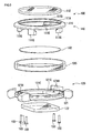
- FIG. 2 is an oblique view of the outside case of the radio-controlled timepiece according to a preferred embodiment of the invention.
- FIG. 3 is a partially exploded view of the outside case of the radio-controlled timepiece according to a preferred embodiment of the invention.
- FIG. 4 is an enlarged section view of the outside circumference part of the outside case of the radio-controlled timepiece according to a preferred embodiment of the invention.
- FIG. 5 is a section view showing the fastening structure of the outside circumference part of the outside case of the radio-controlled timepiece according to a preferred embodiment of the invention.
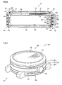
- FIG. 6 is a side section view of a timepiece according to a second embodiment of the invention.
- FIG. 7 is an oblique view of the outside case of the radio-controlled timepiece according to a second embodiment of the invention.
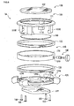
- FIG. 8 is a partially exploded view of the outside case of the radio-controlled timepiece according to a second embodiment of the invention.
- FIG. 9 is an enlarged section view of the outside circumference part of the outside case of the radio-controlled timepiece according to a second embodiment of the invention.
- FIG. 10 is a section view showing the fastening structure of the outside circumference part of the outside case of the radio-controlled timepiece according to a second embodiment of the invention.
- FIG. 1 is a side section view of a radio-controlled timepiece according to a first embodiment of the invention.
- FIG. 2 is an oblique view of the outside case of the radio-controlled timepiece according to a preferred embodiment of the invention.
- FIG. 3 is a partially exploded view of the outside case of the radio-controlled timepiece according to a preferred embodiment of the invention.
- FIG. 4 is an enlarged section view of the outside circumference part of the outside case of the radio-controlled timepiece according to a preferred embodiment of the invention.
- FIG. 5 is a section view showing the fastening structure of the outside circumference part of the outside case of the radio-controlled timepiece according to a preferred embodiment of the invention.
- the radio-controlled timepiece 1 As shown in FIG. 1 , the radio-controlled timepiece 1 according to this embodiment of the invention has an outside case 100, an antenna 200 disposed inside the outside case 100, and a movement 210 as the timekeeping mechanism.
- the outside case 100 includes a retainer ring 110, a back cover 120 disposed opposite the retainer ring 110, and a case body 130 that is held between the retainer ring 110 and the back cover 120.
- the retainer ring 110 has a bezel 111 as a watch crystal retainer unit, and a watch crystal 112.
- the bezel 111 is substantially round and is made of metal or other strong material.
- a shoulder 111A is formed around the inside circumference surface of the bezel 111 for supporting the crystal 112 thereon.
- Packing 113 is disposed between the inside circumference surface (crystal support surface 111B) of the bezel 111 and the outside circumference edge of the crystal 112.
- a bezel-side case retainer 111C for holding the case body 130 is formed around the outside edge of the bezel 111 on the bottom (the side facing the back cover 120).
- the bezel-side case retainer 111C has a bezel-side stop 111D protruding towards the back cover 120, and a bezel-side retaining surface 111E on the outside circumference side of the bezel-side stop 111D.
- the bezel-side stop 111D is disposed, for example, at four locations circumferentially to the bezel-side case retainer 111C, and contacts the inside circumference surface of the case body 130 for positioning. Note that the bezel-side stop 111D is formed at four locations in this embodiment, but the invention is not so limited. For example, there could be three or five or more discretely formed bezel-side stops 111D, or the bezel-side stop 111D could be formed as a single continuous stop around the circumference of the bezel 111.
- a bezel-side packing member 114 is disposed as a shock absorber made of rubber, plastic, or other elastic material inside this bezel-side retainer channel 111F.
- the bezel-side packing member 114 is formed with a substantially circular section that is substantially equal in diameter to the width of the bezel-side retainer channel 111F.
- the bezel-side case retainer 111C holds the case body 130 secure by means of the bezel-side stop 111D positioned in contact with the inside surface of the case body 130 and the case body 130 being held between the bezel-side retaining surface 111E and the back cover 120 through the intervening bezel-side packing member 114.
- back cover retaining flanges 111G are disposed protruding down as shown in FIG. 5 from the inside surface of the bezel-side case retainer 111C of the bezel 111.
- a screw hole 111H is formed in the bottom surface of each back cover retaining flange 111G facing the back cover 120.
- the bottom of these back cover retaining flanges 111G is placed against the top of the back cover 120, and a set screw 150 inserted from the bottom of the back cover 120 is screwed into each screw hole 111H to fasten the back cover 120.
- the back cover retaining flanges 111G are disposed at positions substantially corresponding to the bezel-side stops 111D, but the invention is not so limited and the back cover retaining flanges 111G and the bezel-side stops 111D do not need to be in opposing positions.
- the number of back cover retaining flanges 111G is also not limited to four, but there must be at least three, and there could therefore be only three or five or more back cover retaining flanges 111G.
- the crystal 112 is placed on and bonded by adhesive to the shoulder 111A of the bezel 111.
- Packing 113 is disposed between the crystal 112 and the crystal retaining face 111B of the bezel 111 in order to prevent water from entering between the bezel 111 and the crystal 112 and provide the desired water resistance.
- the back cover 120 includes a back cover retaining ring 121 and a glass cover 122 that is held in the back cover retaining ring 121.
- the back cover retaining ring 121 is made of a high strength material such as metal.
- a substantially square glass retaining hole 121A is formed substantially in the center of the back cover retaining ring 121.
- a glass positioning flange 121B protruding toward the inside is formed at the top edge of the glass retaining hole 121A.
- a substantially square glass cover 122 substantially identical in shape to the glass retaining hole 121A is positioned against the bottom of this glass positioning flange 121B, and affixed thereto by adhesive, for example.
- a glass cover retaining surface 121C that holds the outside edge of the glass cover 122 is formed at the bottom of the inside surface of the glass retaining hole 121A.
- the glass cover retaining surface 121C holds the edge of the glass cover 122 with intervening packing 123.
- a back-cover-side case retainer 121D is formed around the outside edge at the top of the back cover 120 as shown in FIG. 1 , FIG. 4 , and FIG. 5 .
- the back-cover-side case retainer 121D has a back-cover-side stop 121E that protrudes toward the retainer ring 110, and a back-cover-side retainer face 121F rendered on the outside circumference side of the back-cover-side stop 121E.
- the back-cover-side stop 121E is formed circumferentially to the outside circumference of the back-cover-side case retainer 121D.
- the back-cover-side stop 121E contacts the inside circumference of the case body 130 and positions the case body 130.
- the back-cover-side stop 121E is rendered around the entire circumference of the back-cover-side case retainer 121D in this embodiment of the invention, but the invention is not so limited and the back-cover-side stop 121E could be formed similarly to the bezel-side stop 111D at, for example, four locations around the circumference of the back-cover-side case retainer 121D.
- Theback-cover-side retainer face 121F has a back-cover-side retainer channel 121G as a groove that is open to the retainer ring 110 side.
- Abezel-side packing member 114 is disposed as a shock absorber made of rubber, plastic, or other elastic material inside this bezel-side retainer channel 111F.
- a back-cover-side packing member 124 is disposed as a shock absorber made of rubber, plastic, or other elastic material in this back-cover-side retainer channel 121G.
- the back-cover-side packing member 124 is formed with a substantially circular section that is substantially equal in diameter to the width of the back-cover-side retainer channel 121G.
- the back-cover-side case retainer 121D holds the case body 130 secure by means of the back-cover-side stop 121E positioned in contact with the inside surface of the case body 130 and the case body 130 held between the back-cover-side retainer face 121F and the bezel-side retaining surface 111E of the retainer ring 110 through the intervening back-cover-side packing member 124.
- Screw holes 121H for inserting the set screws 150 described above are formed in the back cover retaining ring 121 as shown in FIG. 5 at positions corresponding to the back cover retaining flanges 111G of the retainer ring 110.
- a set screw 150 is inserted to the screw hole 121H and the set screw 150 is screwed into the screw hole 111H in the back cover retaining flanges 111G.
- the back cover 120 and retainer ring 110 are thus held together with the case body 130 therebetween.
- a through-hole 131 A for inserting the stem, not shown in FIG. 6 , of a crown 160 as an operating member is formed in the case body 130.
- the case body 130 is made of glass and is substantially ring shaped, and is held between the back cover 120 and the bezel 111 of the retainer ring 110. As described above, the case body 130 is held by means of the retainer ring 110 and the back cover 120 with the intervening bezel-side packing member 114 and back-cover-side packing member 124. Stress applied to the retainer ring 110 and back cover 120 is thus absorbed by the packing members 114 and 124, and the case body 130 is thus protected from great stress and damage.
- the stem of the crown 160 is inserted through a through-hole and connected to a movement 210 that is the timekeeping unit disposed inside the outside case 100.
- the crown 160 can be rendered to operate in many ways, including outputting signals to a control circuit (not shown) located inside the movement 210 when the crown 160 is pushed in or pulled out from the movement 210, or outputting operating signals to the control circuit unit when the crown 160 is rotatably disposed and the crown 160 is wound.
- a dial 140 is disposed facing the crystal 112 between the retainer ring 110 and the movement 210.
- This dial 140 is made from plastic or other nonmagnetic material, and is fixed to the top of the movement 210.
- a through-hole not shown is formed substantially in the center of the dial 140, and the center pin on which the hands 170 are mounted above the dial 140 passes through this hole.
- the antenna 200 has a magnetic core 201 and a coil 202 wound around the magnetic core 201, and is formed in an arc along the inside circumference face of the case body 130, for example.
- This antenna 200 receives a radio frequency signal (external radio frequency information), and in this embodiment of the invention more particularly receives standard time signals that are transmitted from a known standard time signal broadcasting station and carry time information.
- the received signals are output to a control circuit unit not shown that is built in to the movement 210.
- the movement 210 is housed inside the outside case 100 and is affixed at a prescribed position inside the outside case 100.
- the movement 210 includes a control circuit unit not shown for processing the standard time signals received by the antenna 200, a stepping motor not shown that is driven as controlled by the control circuit unit, and hands 170 (including a second hand 171, an hour hand 173, and a minute hand 172 as shown in FIG. 1 ) that are driven by drive power from the stepping motor.
- the movement 210 keeps the time by means of a counter not shown that is part of the control circuit unit, outputs a predetermined pulse signal to the stepping motor according to the counted time, and thus moves the hands 170. Based on the time information in the standard time signal received by the antenna 200, the movement 210 appropriately drives the stepping motor and controls moving the hands 170 to the hand positions corresponding to the time information in the standard time signal.
- the crystal 112 is first fit into the bezel 111 of the retainer ring 110 to assemble the retainer ring 110, and the glass cover 122 is fit into the back cover retaining ring 121 of the back cover 120 to assemble the back cover 120.
- the bezel-side packing member 114 is then fit into the bezel-side retainer channel 111F of the retainer ring 110, and the back-cover-side packing member 124 is fit into the back-cover-side retainer channel 121G of the back cover 120.
- the movement 210, to which the hands 170 and dial 140 have been attached, is then attached to the retainer ring 110.
- the case body 130 is then mounted on the bezel-side retaining surface 111E of the retainer ring 110.
- the bezel-side stop 111D is set against the inside surface of the case body 130 at this time to position the case body 130.
- the case body 130 is then covered by the back cover 120, and the case body 130 is affixed between the back cover 120 and the retainer ring 110.
- the back-cover-side stop 121E of the back cover 120 is set against the inside circumference surface of the case body 130 at this time.
- the set screws 150 are then passed through the screw holes 121H in the back cover 120, and screwed into the screw holes 111H in the back cover retaining flanges 111G of the retainer ring 110. Tightening the set screws 150 holds the case body 130 firmly between the retainer ring 110 and the back cover 120. Because the case body 130 is held between the retainer ring 110 and the back cover 120 with the intervening bezel-side packing member 114 and back-cover-side packing member 124, the load on the case body 130 is absorbed by the elastic deformation of the packing members 114 and 124.
- the outside case 100 of the radio-controlled timepiece 1 has a retainer ring 110 with a crystal 112, a back cover 120 opposite the retainer ring 110, and a glass case body 130 that is a non-magnetic member held between the retainer ring 110 and back cover 120.
- An antenna 200 for receiving standard time signals and a movement 210 are disposed inside the outside case 100. The movement 210 sets the time based on the time information from the standard time signal received through the antenna 200, and drives the hands 170 to display the time kept by an internal timekeeping unit.
- the case body 130 does not interfere with standard time signal reception, a strong standard time signal can be received by the antenna 200, and the reception sensitivity of the antenna 200 can be improved.
- the case body 130 does not contact the skin when the radio-controlled timepiece 1 is rendered as a wristwatch and is worn with the back cover 120 against the skin, radio frequency signals pass easily through the case body 130 and good reception sensitivity can be achieved even when the invention is applied to a GPS wristwatch or other application that receives signals that can be affected by the body.
- Good reception sensitivity can also be achieved even when the back cover 120 on the opposite side of the radio-control led timepiece 1 as the retainer ring 110 is placed on a stand or other surface made of a non-magnetic material because the case body 130 is non-magnetic and the radio frequency signals can be received through the case body 130.
- the case body 130 is made from a glass ring.
- the case body 130 is thus assured of greater strength than if the case body 130 is rendered using a C-shaped glass member, for example. Furthermore, because standard time signals can pass through the case body 130 around its entire circumference, the reception sensitivity of the antenna can be yet further improved.
- the case body 130 is made of glass.
- the back cover 120 includes a glass cover 122 made of glass, and a back cover retaining ring 121 that protects the outside edge of the glass cover 122.
- the dial 140 is made from a non-magnetic member.
- the arrangement of the invention affords better reception sensitivity even when the antenna 200 is located near the dial 140 because the dial 140 does not interfere with signal reception.
- a through-hole is formed in the back cover retaining ring 121 of the back cover 120, and the stem of the crown 160 passes through this hole.
- the crown 160 is made of a non-magnetic member.
- the crown 160 therefore does not interfere with radio signal reception even when the antenna 200 is disposed near the crown 160, and the reception sensitivity of the antenna 200 can therefore be improved.
- the case body 130 is held between the retainer ring 110 and the back cover 120 by means of intervening bezel-side packing member 114 and back-cover-side packing member 124.
- the packing members 114 and 124 thus form a good water-resistant seal between the case body 130 and the retainer ring 110 and between the case body 130 and the back cover 120. Furthermore, by inserting the packing members 114 and 124 between the case body 130 and the retainer ring 110 and back cover 120, the case body 130 does not directly contact the retainer ring 110 or the 120, stress on the case body 130 is dispersed by the packing members 114 and 124, and damage to the case body 130 when assembling the outside case 100 can be prevented.
- the bezel-side packing member 114 and the back-cover-side packing member 124 are disposed in the mutually opposing annular bezel-side retainer channel 111F and back-cover-side retainer channel 121G.
- the packing members 114 and 124 can be desirably positioned between the retainer ring 110 and case body 130 and between the back cover 120 and case body 130 without shifting radially. A loss of water resistance and a drop in strength caused by shifting of the packing members 114 and 124 can therefore be prevented and a good appearance can be achieved.
- the packing members 114 and 124 are basically circular in section with a diameter that is substantially equal to the width of the bezel-side retainer channel 111F and back-cover-side retainer channel 121G.
- elastic deformation radially to the packing members 114 and 124 is restricted by the side walls of the bezel-side retainer channel 111F and back-cover-side retainer channel 121G, and elastic resilience in the axial direction can therefore be improved.
- the application of stress to the case body 130 can therefore be more effectively prevented, and damage to the case body 130 can be reliably prevented.
- the outside case 100 is assembled to hold the case body 130 between the back cover 120 and the retainer ring 110 by passing set screws 150 through the screw holes 121H disposed in the back cover 120 and threading the set screws 150 into screw holes 111H in the back cover retaining flanges 111G of the retainer ring 110.
- the back cover 120 and retainer ring 110 can thus be reliably and firmly fastened by means of set screws. Because the case body 130 is held between the retainer ring 110 and back cover 120 by intervening packing members 114 and 124 as described above, stress applied axially to the case body 130 by tightening the screws is dispersed by the packing members 114 and 124, thereby reducing the stress on the case body 130 and preventing damage to the case body 130.
- a radio-controlled timepiece according to a second embodiment of the invention is described next with reference to the accompanying figures.
- FIG. 6 is a side section view of a timepiece according to a second embodiment of the invention.
- FIG. 7 is an oblique view of the outside case of the radio-controlled timepiece according to a second embodiment of the invention.
- FIG. 8 is a partially exploded view of the outside case of the radio-controlled timepiece according to a second embodiment of the invention.
- FIG. 9 is an enlarged section view of the outside circumference part of the outside case of the radio-controlled timepiece according to a second embodiment of the invention.
- FIG. 10 is a section view showing the fastening structure of the outside circumference part of the outside case of the radio-controlled timepiece according to a second embodiment of the invention.
- the timepiece 1A As shown in FIG. 1 , the timepiece 1A according to this embodiment of the invention has an outside case 100 and a movement 210 as the timekeeping mechanism.
- the outside case 100 includes a retainer ring 110, a back cover 120 disposed opposite the retainer ring 110, and a case body 130 that is held between the retainer ring 110 and the back cover 120.
- the retainer ring 110 has a bezel 111 as a watch crystal retainer unit, and a watch crystal 112.
- the bezel 111 is substantially round and is made of metal or other strong material.
- a shoulder 111A is formed around the inside circumference surface of the bezel 111 for supporting the crystal 112 thereon.
- Packing 113 is disposed between the inside circumference surface (crystal support surface 111B) of the bezel 111 and the outside circumference edge of the crystal 112.
- a bezel-side case retainer 111C for holding the first glass part 132 of the case body 130 is formed around the outside edge of the bezel 111 on the bottom (the side facing the back cover 120).
- the bezel-side case retainer 111C has a bezel-side stop 111D protruding towards the back cover 120, and a bezel-side retaining surface 111E on the outside circumference side of the bezel-side stop 111D.
- the bezel-side stop 111D is disposed, for example, at four locations circumferentially to the bezel-side case retainer 111C, and contacts the inside circumference surface of the case body 130 for positioning. Note that the bezel-side stop 111D is formed at four locations in this embodiment, but the invention is not so limited. For example, there could be three or five or more discretely formed bezel-side stops 111D, or the bezel-side stop 111D could be formed as a single continuous stop around the circumference of the bezel 111.
- a bezel-side packing member 114 is disposed as a shock absorber made of rubber, plastic, or other elastic material inside this bezel-side retainer channel 111F.
- the bezel-side packing member 114 is formed with a substantially circular section that is substantially equal in diameter to the width of the bezel-side retainer channel 111F.
- the bezel-side case retainer 111C holds the case body 130 secure by means of the bezel-side stop 111D positioned in contact with the inside surface of the case body 130 and the case body 130 being held between the bezel-side retaining surface 111E and the back cover 120 through the intervening bezel-side packing member 114.
- back cover retaining flanges 111G are disposed protruding down as shown in FIG. 10 from the inside surface of the bezel-side case retainer 111C of the bezel 111.
- a screw hole 111H is formed in the bottom surface of each back cover retaining flange 111G facing the back cover 120.
- the bottom of these back cover retaining flanges 111G is placed against the top of the back cover 120, and a set screw 150 inserted from the bottom of the back cover 120 is screwed into each screw hole 111H to fasten the back cover 120.
- the back cover retaining flanges 111G are disposed at positions substantially corresponding to the bezel-side stops 111D, but the invention is not so limited and the back cover retaining flanges 111G and the bezel-side stops 111D do not need to be in opposing positions.
- the number of back cover retaining flanges 111G is also not limited to four, but there must be at least three, and there could therefore be only three or five or more back cover retaining flanges 111G.
- the crystal 112 is placed on and bonded by adhesive to the shoulder 111A of the bezel 111.
- Packing 113 is disposed between the crystal 112 and the crystal retaining face 111B of the bezel 111 in order to prevent water from entering between the bezel 111 and the crystal 112 and provide the desired water resistance.
- the back cover 120 includes a back cover retaining ring 121 and a glass cover 122 that is held in the back cover retaining ring 121.
- the back cover retaining ring 121 is made of a high strength material such as metal.
- a substantially square glass retaining hole 121A is formed substantially in the center of the back cover retaining ring 121.
- a glass positioning flange 121B protruding toward the inside is formed at the top edge of the glass retaining hole 121A.
- a substantially square glass cover 122 substantially identical in shape to the glass retaining hole 121A is positioned against the bottom of this glass positioning flange 121B, and affixed thereto by adhesive, for example.
- a glass cover retaining surface 121C that holds the outside edge of the glass cover 122 is formed at the bottom of the inside surface of the glass retaining hole 121A.
- the glass cover retaining surface 121C holds the edge of the glass cover 122 with intervening packing 123.
- a back-cover-side case retainer 121D is formed at the top around the outside edge of the back cover 120 as shown in FIG. 6 , FIG. 9 , and FIG. 10 .
- the back-cover-side case retainer 121D has a back-cover-side stop 121E that protrudes toward the retainer ring 110, and a back-cover-side retainer face 121F rendered on the outside circumference side of the back-cover-side stop 121E.
- the back-cover-side stop 121E is formed circumferentially to the outside circumference of the back-cover-side case retainer 121D.
- the back-cover-side stop 121E contacts the inside circumference of the case body 130 and positions the case body 130.
- the back-cover-side stop 121E is rendered around the entire circumference of the back-cover-side case retainer 121D in this embodiment of the invention, but the invention is not so limited and the back-cover-side stop 121E could be formed similarly to the bezel-side stop 111D at, for example, four locations around the circumference of the back-cover-side case retainer 121D.
- the back-cover-side retainer face 121F has a back-cover-side retainer channel 121G as a groove that is open to the retainer ring 110 side.
- Abezel-side packing member 114 is disposed as a shock absorber made of rubber, plastic, or other elastic material inside this bezel-side retainer channel 111F.
- a back-cover-side packing member 124 is disposed as a shock absorber made of rubber, plastic, or other elastic material in this back-cover-side retainer channel 121G.
- the back-cover-side packing member 124 is formed with a substantially circular section that is substantially equal in diameter to the width of the back-cover-side retainer channel 121G.
- the back-cover-side case retainer 121D holds the case body 130 secure by means of the back-cover-side stop 121E positioned in contact with the inside surface of the case body 130 and the case body 130 held between the back-cover-side retainer face 121F and the bezel-side retaining surface 111E of the retainer ring 110 through the intervening back-cover-side packing member 124.
- Screw holes 121H for inserting the set screws 150 described above are formed in the back cover retaining ring 121 as shown in FIG. 5 at positions corresponding to the back cover retaining flanges 111G of the retainer ring 110.
- a set screw 150 is inserted to the screw hole 121H and the set screw 150 is screwed into the screw hole 111H in the back cover retaining flanges 111G.
- the back cover 120 and retainer ring 110 are thus held together with the case body 130 therebetween.
- the case body 130 has a substantially annular metal part 131, a first glass part 132 disposed on the retainer ring 110 side of this metal part 131, and a second glass part 133 disposed on the back cover 120 side of the metal part 131.
- the metal part 131 is made of titanium or other metal, a through-hole 131A for inserting the stem of a crown 160 as an operating member is formed passing through the metal part 131.
- a first glass retaining unit 131B is disposed to the metal part 131 on the end opposite the first glass part 132, and a second glass retaining unit 131F is disposed on the opposite end facing the second glass part 133.
- the first glass retaining unit 131B has a first glass stop 131C that protrudes toward the retainer ring 110 and functions as a stop, and a first glass retaining surface 131D formed on the outside circumference side of the first glass stop 131C.
- a first glass stop 131C is rendered at four locations around the circumference of the metal part 131 to contact the inside circumference surface of the first glass part 132 and position the first glass part 132. Note that the first glass stops 131C are formed at four locations in this embodiment, but the invention is not so limited. For example, there could be three or five or more discretely formed first glass stops 131C, or the first glass stop 131C could be formed as a single continuous stop around the circumference of the first glass retaining unit 131B.
- a first glass retaining packing member 134 is disposed as a shock absorber made of rubber, plastic, or other elastic material inside this first glass retaining channel 131E.
- the first glass retaining packing member 134 is formed with a substantially circular section that is substantially equal in diameter to the width of the first glass retaining channel 131E.
- the second glass retaining unit 131F is substantially identical to the first glass retaining unit 131B, and has a second glass stop 131G that protrudes toward the back cover 120 and functions as a stop, and a second glass retaining surface 131H formed on the outside circumference side of the second glass stop 131G.
- a second glass stop 131G is rendered at four locations around the circumference of the metal part 131 to contact the inside circumference surface of the second glass part 133 and position the second glass part 133.
- second glass stops 131G are formed at four locations in this embodiment, but the invention is not so limited. For example, there could be three or five or more discretely formed second glass stops 131G, or the second glass stop 131G could be formed as a single continuous stop around the circumference of the second glass retaining unit 131F.
- a second glass retaining channel 131I formed circumferentially to the second glass retaining surface renders a recessed channel that is open to the back cover 120 side.
- a second glass retaining packing member 135 is disposed as a shock absorber made of rubber, plastic, or other elastic material inside this second glass retaining channel 131I.
- the second glass retaining packing member 135 is formed with a substantially circular section that is substantially equal in diameter to the width of the second glass retaining channel 131I.
- the first glass part 132 is made of glass and is substantially ring shaped, is substantially equal in diameter to the metal part 131, and is disposed substantially coaxially to the metal part 131. Sapphire glass, crystal glass, or other type of glass could be used to make the first glass part 132. As described above, the inside surface of the first glass part 132 is positioned by the first glass stop 131C of the metal part 131 and the bezel-side stop 111D of the retainer ring 110. The first glass part 132 is held between the retainer ring 110 and the metal part 131 by means of the bezel-side packing member 114 and the first glass retaining packing member 134. Stress from the retainer ring 110 and metal part 131 is therefore absorbed by the packing members 114 and 134 and the first glass part 132 is thus protected from great stress and damage.
- the second glass part 133 is made of glass and is substantially ring shaped, is substantially equal in diameter to the metal part 131, and is disposed substantially coaxially to the metal part 131.
- the second glass part 133 is also made of sapphire glass, crystal glass, or other type of glass.
- the inside surface of the second glass part 133 is positioned by the second glass stop 131G of the metal part 131 and the back-cover-side stop 121E of the back cover 120 (see FIG. 9 ).
- the second glass part 133 is held between the back cover 120 and the metal part 131 by means of the back-cover-side packing member 124 and second glass retaining packing member 135.
- stress from the back cover 120 and the metal part 131 is therefore absorbed by the packing members 124 and 135 and the second glass part 133 is thus protected from great stress and damage.
- the stem of the crown 160 is inserted through a through-hole 131A formed in the metal part 131 of the case body 130 as described above, and connected to the movement 210.
- the crown 160 outputs predetermined operating signals to a control circuit unit disposed in the movement 210 when the crown 160 is operated by the user.
- a crown 160 is shown as the operating member by way of example, push-button switches that move in and out of the movement 210 can be used instead.
- a dial 140 is disposed facing the crystal 112 between the retainer ring 110 and the movement 210.
- This dial 140 is made from plastic or other nonmagnetic material, and is fixed to the top of the movement 210.
- a through-hole not shown is formed substantially in the center of the dial 140, and the center pin on which the hands 170 are mounted above the dial 140 passes through this hole.
- the movement 210 has an internal control circuit unit not shown, and moves the hands 170 by driving a stepping motor (not shown in the figure), for example, according to the operating signals input from the crown 160.
- the movement 210 includes a crystal oscillator, for example, and drives the hands 170 at a predetermined drive interval.
- the movement 210 in this embodiment of the invention is for an electronically controlled mechanical timepiece that controls driving the hands 170 by means of a motor based on an operating signal input from the crown 160, but the invention is not so limited and the movement couldbeforamechanical timepiece, an analog quartz type, or a timepiece driven by a different method.
- the movement 210 and timepiece of the invention can be beneficially used in a so-called radio-controlled timepiece that receives a standard time signal carrying time information and sets the time based on the received time information.
- the crystal 112 is first fit into the bezel 111 of the retainer ring 110 to assemble the retainer ring 110, and the glass cover 122 is fit into the back cover retaining ring 121 of the back cover 120 to assemble the back cover 120.
- the bezel-side packing member 114 is then fit into the bezel-side retainer channel 111F of the retainer ring 110, and the back-cover-side packing member 124 is fit into the back-cover-side retainer channel 121G of the back cover 120.
- the first glass retaining packing member 134 and the second glass retaining packing member 135 are also respectively fit into the first glass retaining channel 131E and the second glass retaining channel 131I of the metal part 131 of the case body 130.
- the movement 210, to which the hands 170 and dial 140 have been attached, is then attached to the retainer ring 110.
- the first glass part 132 is then mounted on the bezel-side retaining surface 111E of the retainer ring 110.
- the first glass part 132 is positioned by setting its inside surface against the bezel-side stop 111D at this time.
- the metal part 131 is then placed on the first glass part 132.
- the metal part 131 is positioned at this time by setting the first glass stop 131C against the inside surface of the first glass part 132.
- the second glass part 133 is then placed on the metal part 131.
- the second glass part 133 is positioned to the metal part 131 at this time by setting the inside surface of the second glass part 133 against the second glass stop 131G of the metal part 131.
- the top (exposed edge) of the second glass part 133 is then covered by the back cover 120.
- the second glass part 133 and back cover 120 are positioned at this time by setting the back-cover-side stop 121E against the inside surface of the second glass part 133.
- the set screws 150 are then passed through the screw holes 121H in the back cover 120, and screwed into the screw holes 111H in the back cover retaining flanges 111G of the retainer ring 110. Tightening the set screws 150 holds the case body 130 firmly between the retainer ring 110 and the back cover 120.
- the load on the first glass part 132 is absorbed by the elastic deformation of the packing members 114 and 134.
- the second glass part 133 of the case body 130 is held between the back cover 120 and the metal part 131 with the intervening back-cover-side packing member 124 and second glass retaining packing member 135, elastic deformation of the packing members 124 and 135 absorbs the load on the second glass part 133.
- the case body 130 of a timepiece 1A has a substantially annular metal part 131, a first glass part 132 disposed between this metal part 131 and a retainer ring 110, and a second glass part 133 disposed between the metal part 131 and the back cover 120.
- Athrough-hole 131A for inserting the stem of a crown 160 is also formed in the metal part 131.
- the inside of the timepiece 1A can therefore be seen from the side because the first glass part 132 and the second glass part 133 are made of glass.
- a timepiece 1A with a good appearance can also be achieved using the sense of high quality uniquely afforded by glass.
- the through-hole 131A for passing the stem of the crown 160 is formed in the metal part 131, the durability of the first glass part 132 and second glass part 133 is not reduced, and a crown 160 can be passed through the case body 130.
- Packing members 114, 134, 135, and 124 are respectively disposed between the retainer ring 110 and the first glass part 132, between the first glass part 132 and the metal part 131, between the second glass part 133 and the metal part 131, and between the second glass part 133 and the back cover 120.
- the bezel-side packing member 114, back-cover-side packing member 124, first glass retaining packing member 134, and second glass retaining packing member 135 are respectively disposed in a bezel-side retainer channel 111F, a back-cover-side retainer channel 121G, a first glass retaining channel 131E, and a second glass retaining channel 131I.
- packing members 114, 124, 134, and 135 can be positioned without shifting radially between the retainer ring 110 and first glass part 132, between the first glass part 132 and the metal part 131, between the metal part 131 and the second glass part 133, and between the second glass part 133 and the back cover 120.
- a loss of strength caused by the packing members 114, 124, 134, and 135 shifting can thus be prevented, and a good appearance can be achieved.
- the timepiece 1A uses packing members 114 and 124 as the shock absorbers. As a result, the water resistance of the timepiece 1A can be improved.
- the metal part 131 also has a first glass stop 131C for positioning the first glass part 132, and a second glass stop 131G for positioning the second glass part 133. This prevents the first glass part 132, the metal part 131, and the second glass part 133 from shifting radially in position, and thereby maintains a good appearance and strength.
- the outside case 100 is assembled with the case body 130 held between the back cover 120 and the retainer ring 110 by inserting set screws 150 from the screw holes 121H in the metal back cover 120 and screwing the set screws 150 into the screw holes 111H formed in the back cover retaining flanges 111G protruding from the metal bezel 111 of the retainer ring 110.
- the strength of the timepiece 1A can thus be improved by threading screws into metal parts of the back cover 120 and retainer ring 110. Furthermore, because the first glass part 132 and the second glass part 133 are held between the retainer ring 110, back cover 120, and metal part 131 by means of the packing members 114, 124, 134, and 135, extreme stress applied axially by tightening the screws can be dispersed by the packing members 114, 124, 134, and 135.
- the packing members 114, 124, 134, and 135 are formed with a substantially round section with a diameter substantially equal to the width of the matching bezel-side retainer channel 111F, back-cover-side retainer channel 121G, first glass retaining channel 131E, and second glass retaining channel 131I.
- the radio-controlled timepiece could be a digital timepiece that has a liquid crystal display panel or other display area, and a drive control circuit unit that controls the LCD or other display to present the time.
- the antenna 200 is disposed substantially along the inside surface of the case body 130, but a bar antenna or antenna of some other shape can be disposed inside the outside case 100.
- the case body 130 is made of glass in the first embodiment of the invention, but the case body 130 can be made of plastic or other non-magnetic material.
- the case body 130 is also not limited to transparent glass enabling viewing the inside of the radio-controlled timepiece 1 from the outside, and can be made of, for example, colored glass instead.
- the dial 140 and crown 160 are non-magnetic members, but can be made of a magnetic member such as metal. If the dial 140 is metal, the timepiece display can be imparted with a high quality appearance, and the design of the timepiece can be improved. If the dial 140 is made from a magnetic material, interference by the dial 140 with radio frequency reception can be reduced by positioning the antenna 200 near the glass cover 122 of the back cover 120. If the crown 160 is made from a magnetic material, interference with radio frequency reception can be reduced and good reception sensitivity can be achieved by positioning the antenna 200 away from the crown 160.
- a through-hole is formed in the back cover retaining ring 121 of the back cover 120 for inserting the stem of the crown 160, but the through-hole could be formed in the bezel 111 of the retainer ring 110 and the crown 160 could be inserted through the retainer ring 110.
- the case body 130 is held between the retainer ring 110 and the back cover 120 by intervening packing members 114 and 124, but the invention is not so limited. More specifically, stress is applied to the case body 130 from both the retainer ring 110 and the back cover 120 sides when the set screws are tightened in the first embodiment. However, the case body 130 could be bonded to the retainer ring 110 and the back cover 120 by adhesive, rendering a construction that prevents damage to the case body 130 by not applying stress to the case body 130. Replacing the battery and maintenance are enabled in this case by disposing the glass cover 122 of the back cover 120 removably from the back cover retaining ring 121. This also applies to the second embodiment. More specifically, the first glass part 132 and retainer ring 110, the second glass part 133 and back cover 120, the metal part 131 and first glass part 132, and the metal part 131 and second glass part 133 can be respectively bonded to each other using an adhesive.
- the packing members 114 and 124 are fit into the bezel-side retainer channel 111F and back-cover-side retainer channel 121G.
- annular channels could be formed in the surface of the retainer ring 110 facing the case body 130 and the surface of the back cover 120 facing the case body 130, and the packing members 114 and 124 can be fit into these grooves. It is also possible to omit the grooved channels in which these packing members 114 and 124 are fit. This also applies to the second embodiment, wherein grooves for holding the packing members 114, 124, 134, and 135 are omitted.
- the set screws 150 are inserted from the screw holes 121H in the back cover 120 and threaded into the screw holes 111H to hold the retainer ring 110 and back cover 120 together.
- any method of securing the retainer ring 110 and back cover 120 without interfering with standard time signal reception by the antenna 200 can be used, including bonding the retainer ring 110 and back cover 120 together with an adhesive as described above.
- packing members 114 and 124 are disposed as shock absorbers between the retainer ring 110 and case body 130 and between the back cover 120 and case body 130, but the invention is not so limited.
- the shock absorbing members can be rendered using a different type of elastic shock absorbing material, such as an elastic sponge material, so that stress applied to the case body 130 can be absorbed by the elastic shock absorbing member.
- the invention is also not limited to an annular shock absorbing member, and a plurality of shock absorbing members can be rendered with a specific interval therebetween at predetermined positions to the bezel-side retainer channel 111F and back-cover-side retainer channel 121G. As described above, stress applied to the case body 130 can also be absorbed by these shock absorbing members. Note, further, that by placing a water-resistant adhesive between the retainer ring 110 and the case body 130, and between the back cover 120 and the case body 130, in the two preceding examples, a drop in the water resistance can be prevented.
- An elastic sponge member or other type of elastic shock absorbing member can likewise be used as the shock absorbing member in the foregoing second embodiment.
- the shock absorbing member is also not limited to a ring-shaped member, and a plurality of shock absorbing members can be rendered with a specific interval therebetween at predetermined positions to the bezel-side retainer channel 111F, the back-cover-side retainer channel 121G, the first glass retaining channel 131E, and the second glass retaining channel 131I.
- stress applied to the first glass part 132 and second glass part 133 can also be absorbed by these shock absorbing members.
- the case body 130 is entirely made of glass in the first embodiment described above, but the invention is not so limited.
- both annular ends of the case body 130 could be made from a metal or other magnetic member sandwiching a glass ring member therebetween. This arrangement enables the standard time signal waves to pass freely through the glass part of the case body 130, and thereby improves the reception sensitivity of the antenna 200.
- first glass part 132 and the second glass part 133 are described as being made entirely from glass, but the invention is not so limited. More specifically, a metal ring could be disposed to both annular ends of the glass ring members so that each glass ring member is sandwiched between the metal members.
- the back cover 120 is described having a substantially rectangular glass cover 122 disposed in a glass retaining hole 121A rendered in the back cover retaining ring 121, but the invention is not so limited.
- the glass cover 122 could be rendered as a circular arc over the antenna 200, or otherwise shaped suitably according to the shape of the antenna 200.
- a standard time signal is used above by way of example as the received radio frequency signal (external radio information), but the invention is not so limited.
- the received radio signals could be FM signals, GPS signals, radio frequencies that are used for cell phone communications, wireless data signals including Bluetooth and contactless IC cards, news broadcasts and weather reports, or other type of external wireless signal.
- the design of the antenna 200 and the control circuit unit will vary according to the type of signals received. For example, if the received external wireless information is a weather report, an indicator can be driven by a stepping motor to point to an appropriate weather icon, such as sunny, cloudy, or rain. News, stock prices, and other information can also be displayed using a liquid crystal display or other type of digital display.
- the first glass part 132 and second glass part 133 are made of transparent glass so that the inside of the radio-controlled timepiece 1 can be seen.
- the first glass part 132 and second glass part 133 can be made from translucent glass colored a specific color, or opaque glass. If opaque glass is used the inside of the timepiece cannot be seen from the side of the timepiece, but the high quality appearance imparted by the glass canbe used to give the timepiece a nice appearance.
Landscapes
- Physics & Mathematics (AREA)
- General Physics & Mathematics (AREA)
- Electric Clocks (AREA)
Abstract
Description
- The present invention relates to a timepiece with a built-in antenna.
- Japanese Unexamined Patent Appl. Pub.
JP-A-2006-275580 JP-A-02-116784 - The radio-controlled timepiece taught in Japanese Unexamined Patent Appl. Pub.
JP-A-2006-275580 - Japanese Unexamined Patent Appl. Pub.
JP-A-02-116784 - Disposing non-magnetic parts in a part of the radio-controlled timepiece renders an arrangement that reduces disruption of resonance near the receiver part of the radio-controlled timepiece, but sufficient reception sensitivity cannot be achieved because the timepiece case and back cover are metal. A problem with the skeleton timepiece such as taught in Japanese Unexamined Patent Appl. Pub.
JP-A-02-116784 - A timepiece according to the present invention achieves both good reception sensitivity and durability.
- A first aspect of the invention is a timepiece having: a retainer ring including a timepiece crystal and a glass retaining unit that holds the outside edge of the crystal; a back cover that is disposed facing the retainer ring; a case member that is substantially annular, is made at least in part from a non-magnetic member, and links the outside edges of the retainer ring and the back cover; an antenna that is disposed in a space formed between the retainer ring and the back cover, and can receive radio signals that pass through the non-magnetic member of the case member to the inside of the case member; and a timekeeping unit that is disposed in a space formed between the retainer ring and the back cover, and has a time display unit for displaying the time.
- At least part of the case member that connects the outside edges of the retainer ring and back cover is formed by a non-magnetic member in a timepiece according to this aspect of the invention. An antenna that can receive predetermined radio signals (external wireless information) is disposed in the space between the retainer ring and the back cover, or more particularly inside the case rendered by the retainer ring, the back cover, and the case member.
- By thus rendering at least part of the case member from a non-magnetic material, radio frequency signals can pass through the non-magnetic part of the side of the timepiece, can be received by the antenna with good signal strength, and reception sensitivity can thus be improved.
- Furthermore, because a non-magnetic member is included in the case member and RF signals can therefore pass into the case through the side of the timepiece, the reception sensitivity of the antenna can be improved compared with a wristwatch that has a back cover made of glass or other non-magnetic member and a metal case member. More specifically, when GPS signals, for example, are the received radio frequency signals in a timepiece that has a back cover made of glass or other non-magnetic material, the GPS signal reception sensitivity is reduced when the back cover is in contact with the skin when the wristwatch is worn on the wrist. The reception sensitivity of the antenna also drops when the wristwatch band is metal and the wristwatch is removed from the wrist and placed with the metal band near the back cover. However, by rendering a non-magnetic member in at least part of the case member, external wireless information such as carried by GPS signals can be received with good signal strength even when the wristwatch is worn on the wrist because the non-magnetic case member does not contact the wrist. Furthermore, even if a metal band is used as the wristwatch band, the metal band will not contact the case member when the wristwatch is removed from the wrist, and good reception sensitivity can be maintained. The reception sensitivity of the antenna is therefore better than when the back cover is made from a non-magnetic member.
- Examples of the radio frequency signals received by the antenna include standard time signals carrying time information, GPS signals, and cell phone signals, and the correct time can be displayed by adjusting the time displayed on the time display unit (the movement of an analog timepiece or the timekeeping module of a digital timepiece) of the timekeeping unit (the hands and dial of an analog timepiece, or the liquid crystal display or organic electroluminescent display of a digital timepiece) based on the time information decoded from the received signal.
- Furthermore, because the RF signals can pass into the case from the side of the time piece case (case member) , signals can be received by the antenna even if the dial or back cover is metal. A metal dial, which is conventionally difficult to use in a radio-controlled timepiece, can therefore be used in a radio-controlled timepiece, and the design of the dial can be improved.
- Preferably, the non-magnetic member of the case member is formed in a ring around the circumference of the case member.
- The non-magnetic member in this aspect of the invention is formed in a ring around the circumference of the case member. Compared with an arrangement in which the non-magnetic member is formed in a C-shape circumferentially to the case member, rendering the non-magnetic member as a closed ring improves the radial durability and strength and provides greater protection against damage caused by impact.
- Furthermore, because the non-magnetic member is disposed around the full circumference on the side of the timepiece, radio signals can pass through the non-magnetic member from any direction, and the reception sensitivity of the antenna can be improved.
- Further preferably, the case member is made from glass, which is a non-magnetic member.
- By making the case member from glass, a timepiece with an outstanding design, including being able to see inside the timepiece through the case member, can be provided.
- Yet further preferably, the back cover includes a flat non-magnetic member, and a retainer part that holds the outside edge of the non-magnetic member.
- By thus rendering the back cover with glass or other non-magnetic member, the antenna can be disposed near the back cover with the part of the back cover near the antenna being a non-magnetic member so that there are no metal or other magnetic parts near the antenna. This improves the reception sensitivity of the antenna compared with an arrangement in which the entire back cover is metal.
- Yet further preferably, the time display unit of the timekeeping unit has hands and a dial; and the dial is a non-magnetic member.
- Because the dial is a non-magnetic member in this aspect of the invention, the dial does not interfere with signal reception even when the antenna is located near the dial, and reception sensitivity is thus improved compared with an arrangement using a metal dial.
- In another preferred aspect of the invention the timepiece also has an operating unit for operating the timekeeping unit; and a through-hole formed in the glass retaining unit of the retainer ring or the back cover for inserting the stem of the operating unit.
- This aspect of the invention renders a hole for inserting the stem of a button, crown, or other operating member for operating the timekeeping unit in the glass retaining unit of the retainer ring or the back cover. It is therefore not necessary to form a hole for inserting the stem of the operating member in the case member, and the strength of a glass case member can therefore be maintained.
- Furthermore, because the glass retaining unit of the retainer ring can be made of metal, sufficient strength can be maintained even when such a through-hole is formed.
- If the back cover includes a non-magnetic member of glass, for example, and a retaining unit that holds the outside edge of this non-magnetic member, the through-hole can be formed in the retaining unit. Because the retaining unit of the back cover can be made of metal, sufficient strength can be maintained even if such a through-hole is formed in the retaining unit.
- Yet further preferably, the operating unit is a non-magnetic member.
- The operating unit disposed in the through-hole in the retainer ring or back cover is a non-magnetic member in this aspect of the invention. The antenna can therefore be disposed near the operating unit without the operating unit interfering with signal reception. The signal reception sensitivity of the antenna is therefore good.
- Another aspect of the invention is a timepiece that has a retainer ring including a timepiece crystal and a glass retaining unit that holds the outside edge of the crystal; a back cover that is disposed facing the retainer ring; a substantially annular case member that is held between the retainer ring and the back cover; a timekeeping unit that is disposed in the space enclosed between the retainer ring, the back cover, and the case member, and has a time display unit for displaying the time; and an operating unit that is connected to the timekeeping unit and enables controlling the operating content of the timekeeping unit. The case member has a metal part that is formed substantially in a ring from a metal material and has a through-hole for inserting the stem of the operating unit, a substantially annular first glass part that is made from glass at least in part and is disposed between the metal part and the retainer ring, and a substantially annular second glass part that is made from glass at least in part and is disposed between the metal part and the back cover.
- The case member of the timepiece according to this aspect of the invention has a substantially annular metal part, a first glass part disposed between this metal part and the retainer ring, and a second glass part disposed between the metal part and the back cover. A through-hole for inserting the stem of the operating unit is formed in the metal part.
- As a result, the inside of the timepiece can be seen from the outside through the first and second glass parts, and the unique effect of glass can be used to achieve a nice appearance. Furthermore, because the through-hole is formed in the metal part of the case member, the stem of a crown or other operating member can be inserted through the case member without reducing the durability of the case member. A timepiece with good durability and an excellent appearance can thus be provided.
- Yet further preferably, a shock absorbing member is disposed between the first glass part and the retainer ring, between the first glass part and the metal part, between the second glass part and the metal part, and between the second glass part and the back cover.
- By thus disposing a shock absorbing member between the metal part of the case member and first and second glass parts, between the retainer ring and the first glass part, and between the back cover and the second glass part, the shock absorbing members attenuate the stress when great stress is applied to the timepiece during timepiece assembly. A high stress load is therefore not applied directly to the first glass part and second glass part, and damage to the first and second glass parts can be prevented.
- Yet further preferably, a substantially annular channel is formed following the edge of the case member on the surface of the retainer ring facing the first glass part, the surface of the back cover facing the second glass part, the face of the metal part facing the first glass part, and the face of the metal part facing the second glass part; and the shock absorbing members are disposed in said annular channels.
- This aspect of the invention has a groove on the surfaces of the retainer ring and the metal part facing the first glass part, and on the surfaces of the back cover and metal part facing the second glass part, and the shock absorbing members are disposed in these grooves. This avoids problems caused by the shock absorbing members shifting position during timepiece assembly, and effectively prevents applying stress to the first and second glass parts. Furthermore, because the shock absorbing members are disposed along the grooves, the shock absorbing members are difficult to see from the outside and a timepiece with a good appearance can thus be provided.
- Yet further preferably, the shock absorbing member is a substantially annular packing member that seals between the first glass part and the retainer ring, between the first glass part and the metal part, between the second glass part and the metal part, and between the second glass part and the back cover.
- This aspect of the invention uses packing members as the shock absorbing members. Water resistance can therefore be improved between the first glass part and the retainer ring, between the first glass part and the metal part, between the second glass part and the metal part, and between the second glass part and the back cover.
- Yet further preferably, the metal part has an engaging part that engages the first glass part and the second glass part, and positions the first glass part and the second glass part coaxially to the metal part.
- In this aspect of the invention the metal part has engaging parts (stops) that position the first glass part and the second glass part. Problems resulting from misalignment of the metal part to the first and second glass parts during timepiece assembly can thus be prevented. If stress is applied to the timepiece from the side, the engaging parts can also prevent the first glass part and the second glass part from shifting sideways. A good appearance can thus be maintained while timepiece durability can also be improved.
- Yet further preferably, the glass retaining part of the retainer ring has a back cover locking part that projects toward the back cover, and the protruding distal end of the back cover locking part contacts the back cover and has a screw screwed therein through the back cover; and the case member is held between the glass retaining part of the retainer ring and the back cover with an intervening shock absorbing member.
- The back cover locking part in this aspect of the invention can hold a prescribed gap between the retainer ring and the back cover. When the back cover locking part is fastened by screws to the back cover with the case member therebetween, the back cover locking part holds a prescribed gap between the retainer ring and the back cover, and prevents applying excessive stress to the case member. Damage to the first glass part and the second glass part of the case member can also be reliably prevented.
- Other objects and attainments together with a fuller understanding of the invention will become apparent and appreciated by referring to the following description and claims taken in conjunction with the accompanying drawings.
-
FIG. 1 is a side section view of a radio-controlled timepiece according to a first embodiment of the invention. -
FIG. 2 is an oblique view of the outside case of the radio-controlled timepiece according to a preferred embodiment of the invention. -
FIG. 3 is a partially exploded view of the outside case of the radio-controlled timepiece according to a preferred embodiment of the invention. -
FIG. 4 is an enlarged section view of the outside circumference part of the outside case of the radio-controlled timepiece according to a preferred embodiment of the invention. -
FIG. 5 is a section view showing the fastening structure of the outside circumference part of the outside case of the radio-controlled timepiece according to a preferred embodiment of the invention. -
FIG. 6 is a side section view of a timepiece according to a second embodiment of the invention. -
FIG. 7 is an oblique view of the outside case of the radio-controlled timepiece according to a second embodiment of the invention. -
FIG. 8 is a partially exploded view of the outside case of the radio-controlled timepiece according to a second embodiment of the invention. -
FIG. 9 is an enlarged section view of the outside circumference part of the outside case of the radio-controlled timepiece according to a second embodiment of the invention. -
FIG. 10 is a section view showing the fastening structure of the outside circumference part of the outside case of the radio-controlled timepiece according to a second embodiment of the invention. - * Embodiment 1
- A radio-controlled timepiece according to a preferred embodiment of the present invention is described below with reference to the accompanying figures.
-
FIG. 1 is a side section view of a radio-controlled timepiece according to a first embodiment of the invention. -
FIG. 2 is an oblique view of the outside case of the radio-controlled timepiece according to a preferred embodiment of the invention. -
FIG. 3 is a partially exploded view of the outside case of the radio-controlled timepiece according to a preferred embodiment of the invention. -
FIG. 4 is an enlarged section view of the outside circumference part of the outside case of the radio-controlled timepiece according to a preferred embodiment of the invention. -
FIG. 5 is a section view showing the fastening structure of the outside circumference part of the outside case of the radio-controlled timepiece according to a preferred embodiment of the invention. - As shown in
FIG. 1 , the radio-controlled timepiece 1 according to this embodiment of the invention has anoutside case 100, anantenna 200 disposed inside theoutside case 100, and amovement 210 as the timekeeping mechanism. - The
outside case 100 includes aretainer ring 110, aback cover 120 disposed opposite theretainer ring 110, and acase body 130 that is held between theretainer ring 110 and theback cover 120. - As shown in
FIG. 1 to FIG. 5 , theretainer ring 110 has abezel 111 as a watch crystal retainer unit, and awatch crystal 112. - In this embodiment of the invention the
bezel 111 is substantially round and is made of metal or other strong material. - A
shoulder 111A is formed around the inside circumference surface of thebezel 111 for supporting thecrystal 112 thereon.Packing 113 is disposed between the inside circumference surface (crystal support surface 111B) of thebezel 111 and the outside circumference edge of thecrystal 112. - A bezel-
side case retainer 111C for holding thecase body 130 is formed around the outside edge of thebezel 111 on the bottom (the side facing the back cover 120). The bezel-side case retainer 111C has a bezel-side stop 111D protruding towards theback cover 120, and a bezel-side retaining surface 111E on the outside circumference side of the bezel-side stop 111D. - The bezel-
side stop 111D is disposed, for example, at four locations circumferentially to the bezel-side case retainer 111C, and contacts the inside circumference surface of thecase body 130 for positioning. Note that the bezel-side stop 111D is formed at four locations in this embodiment, but the invention is not so limited. For example, there could be three or five or more discretely formed bezel-side stops 111D, or the bezel-side stop 111D could be formed as a single continuous stop around the circumference of thebezel 111. - A bezel-
side retainer channel 111F formed substantially around the circumference of the bezel-side retaining surface 111E renders a recessed channel that is open to theback cover 120 side. A bezel-side packing member 114 is disposed as a shock absorber made of rubber, plastic, or other elastic material inside this bezel-side retainer channel 111F. The bezel-side packing member 114 is formed with a substantially circular section that is substantially equal in diameter to the width of the bezel-side retainer channel 111F. As a result, when stress is applied to the bezel-side packing member 114 in the axial direction, deflection substantially perpendicularly to the axial direction is limited by the side walls of the bezel-side retainer channel 111F, and thus increases the elastic resilience of the bezel-side packing member 114 in line with the axial direction. - The bezel-
side case retainer 111C holds thecase body 130 secure by means of the bezel-side stop 111D positioned in contact with the inside surface of thecase body 130 and thecase body 130 being held between the bezel-side retaining surface 111E and theback cover 120 through the intervening bezel-side packing member 114. - Four back
cover retaining flanges 111G are disposed protruding down as shown inFIG. 5 from the inside surface of the bezel-side case retainer 111C of thebezel 111. Ascrew hole 111H is formed in the bottom surface of each backcover retaining flange 111G facing theback cover 120. The bottom of these backcover retaining flanges 111G is placed against the top of theback cover 120, and aset screw 150 inserted from the bottom of theback cover 120 is screwed into eachscrew hole 111H to fasten theback cover 120. - The back
cover retaining flanges 111G are disposed at positions substantially corresponding to the bezel-side stops 111D, but the invention is not so limited and the backcover retaining flanges 111G and the bezel-side stops 111D do not need to be in opposing positions. The number of backcover retaining flanges 111G is also not limited to four, but there must be at least three, and there could therefore be only three or five or more backcover retaining flanges 111G. - The
crystal 112 is placed on and bonded by adhesive to theshoulder 111A of thebezel 111.Packing 113 is disposed between thecrystal 112 and thecrystal retaining face 111B of thebezel 111 in order to prevent water from entering between thebezel 111 and thecrystal 112 and provide the desired water resistance. - The
back cover 120 includes a backcover retaining ring 121 and aglass cover 122 that is held in the backcover retaining ring 121. - The back
cover retaining ring 121 is made of a high strength material such as metal. A substantially squareglass retaining hole 121A is formed substantially in the center of the backcover retaining ring 121. Aglass positioning flange 121B protruding toward the inside is formed at the top edge of theglass retaining hole 121A. A substantiallysquare glass cover 122 substantially identical in shape to theglass retaining hole 121A is positioned against the bottom of thisglass positioning flange 121B, and affixed thereto by adhesive, for example. A glasscover retaining surface 121C that holds the outside edge of theglass cover 122 is formed at the bottom of the inside surface of theglass retaining hole 121A. The glasscover retaining surface 121C holds the edge of theglass cover 122 with intervening packing 123. - A back-cover-
side case retainer 121D is formed around the outside edge at the top of theback cover 120 as shown inFIG. 1 ,FIG. 4 , andFIG. 5 . The back-cover-side case retainer 121D has a back-cover-side stop 121E that protrudes toward theretainer ring 110, and a back-cover-side retainer face 121F rendered on the outside circumference side of the back-cover-side stop 121E. - The back-cover-
side stop 121E is formed circumferentially to the outside circumference of the back-cover-side case retainer 121D. The back-cover-side stop 121E contacts the inside circumference of thecase body 130 and positions thecase body 130. The back-cover-side stop 121E is rendered around the entire circumference of the back-cover-side case retainer 121D in this embodiment of the invention, but the invention is not so limited and the back-cover-side stop 121E could be formed similarly to the bezel-side stop 111D at, for example, four locations around the circumference of the back-cover-side case retainer 121D. - Theback-cover-side retainer face 121F has a back-cover-
side retainer channel 121G as a groove that is open to theretainer ring 110 side. Abezel-side packing member 114 is disposed as a shock absorber made of rubber, plastic, or other elastic material inside this bezel-side retainer channel 111F. A back-cover-side packing member 124 is disposed as a shock absorber made of rubber, plastic, or other elastic material in this back-cover-side retainer channel 121G. Like the bezel-side packing member 114 described above, the back-cover-side packing member 124 is formed with a substantially circular section that is substantially equal in diameter to the width of the back-cover-side retainer channel 121G. As a result, when stress is applied to the back-cover-side packing member 124 in the axial direction, deflection substantially perpendicularly to the axial direction is limited by the side walls of the back-cover-side retainer channel 121G, and the elastic resilience of the bezel-side packing member 114 in line with the axial direction. - The back-cover-
side case retainer 121D holds thecase body 130 secure by means of the back-cover-side stop 121E positioned in contact with the inside surface of thecase body 130 and thecase body 130 held between the back-cover-side retainer face 121F and the bezel-side retaining surface 111E of theretainer ring 110 through the intervening back-cover-side packing member 124. - Screw holes 121H for inserting the
set screws 150 described above are formed in the backcover retaining ring 121 as shown inFIG. 5 at positions corresponding to the backcover retaining flanges 111G of theretainer ring 110. - As described above, a
set screw 150 is inserted to thescrew hole 121H and theset screw 150 is screwed into thescrew hole 111H in the backcover retaining flanges 111G. Theback cover 120 andretainer ring 110 are thus held together with thecase body 130 therebetween. - As shown in
FIG. 6 , a through-hole 131 A for inserting the stem, not shown inFIG. 6 , of acrown 160 as an operating member is formed in thecase body 130. - The
case body 130 is made of glass and is substantially ring shaped, and is held between theback cover 120 and thebezel 111 of theretainer ring 110. As described above, thecase body 130 is held by means of theretainer ring 110 and theback cover 120 with the intervening bezel-side packing member 114 and back-cover-side packing member 124. Stress applied to theretainer ring 110 andback cover 120 is thus absorbed by the packingmembers case body 130 is thus protected from great stress and damage. - As described above, the stem of the
crown 160 is inserted through a through-hole and connected to amovement 210 that is the timekeeping unit disposed inside theoutside case 100. Thecrown 160 can be rendered to operate in many ways, including outputting signals to a control circuit (not shown) located inside themovement 210 when thecrown 160 is pushed in or pulled out from themovement 210, or outputting operating signals to the control circuit unit when thecrown 160 is rotatably disposed and thecrown 160 is wound. - A
dial 140 is disposed facing thecrystal 112 between theretainer ring 110 and themovement 210. Thisdial 140 is made from plastic or other nonmagnetic material, and is fixed to the top of themovement 210. A through-hole not shown is formed substantially in the center of thedial 140, and the center pin on which thehands 170 are mounted above thedial 140 passes through this hole. - As shown in
FIG. 1 , theantenna 200 has amagnetic core 201 and acoil 202 wound around themagnetic core 201, and is formed in an arc along the inside circumference face of thecase body 130, for example. Thisantenna 200 receives a radio frequency signal (external radio frequency information), and in this embodiment of the invention more particularly receives standard time signals that are transmitted from a known standard time signal broadcasting station and carry time information. The received signals are output to a control circuit unit not shown that is built in to themovement 210. - The
movement 210 is housed inside theoutside case 100 and is affixed at a prescribed position inside theoutside case 100. - The
movement 210 includes a control circuit unit not shown for processing the standard time signals received by theantenna 200, a stepping motor not shown that is driven as controlled by the control circuit unit, and hands 170 (including asecond hand 171, anhour hand 173, and aminute hand 172 as shown inFIG. 1 ) that are driven by drive power from the stepping motor. - The
movement 210 keeps the time by means of a counter not shown that is part of the control circuit unit, outputs a predetermined pulse signal to the stepping motor according to the counted time, and thus moves thehands 170. Based on the time information in the standard time signal received by theantenna 200, themovement 210 appropriately drives the stepping motor and controls moving thehands 170 to the hand positions corresponding to the time information in the standard time signal. - * Assembling the outside case of the radio-controlled timepiece
- A preferred method of assembling the
outside case 100 of the radio-controlled timepiece 1 according to this embodiment of the invention is described next. - To assemble the radio-controlled timepiece 1, the
crystal 112 is first fit into thebezel 111 of theretainer ring 110 to assemble theretainer ring 110, and theglass cover 122 is fit into the backcover retaining ring 121 of theback cover 120 to assemble theback cover 120. The bezel-side packing member 114 is then fit into the bezel-side retainer channel 111F of theretainer ring 110, and the back-cover-side packing member 124 is fit into the back-cover-side retainer channel 121G of theback cover 120. - The
movement 210, to which thehands 170 and dial 140 have been attached, is then attached to theretainer ring 110. - The
case body 130 is then mounted on the bezel-side retaining surface 111E of theretainer ring 110. The bezel-side stop 111D is set against the inside surface of thecase body 130 at this time to position thecase body 130. - The
case body 130 is then covered by theback cover 120, and thecase body 130 is affixed between theback cover 120 and theretainer ring 110. The back-cover-side stop 121E of theback cover 120 is set against the inside circumference surface of thecase body 130 at this time. - The
set screws 150 are then passed through the screw holes 121H in theback cover 120, and screwed into the screw holes 111H in the backcover retaining flanges 111G of theretainer ring 110. Tightening theset screws 150 holds thecase body 130 firmly between theretainer ring 110 and theback cover 120. Because thecase body 130 is held between theretainer ring 110 and theback cover 120 with the intervening bezel-side packing member 114 and back-cover-side packing member 124, the load on thecase body 130 is absorbed by the elastic deformation of the packingmembers - * Effect of the radio-controlled timepiece
- As described above, the
outside case 100 of the radio-controlled timepiece 1 according to this embodiment of the invention has aretainer ring 110 with acrystal 112, aback cover 120 opposite theretainer ring 110, and aglass case body 130 that is a non-magnetic member held between theretainer ring 110 andback cover 120. Anantenna 200 for receiving standard time signals and amovement 210 are disposed inside theoutside case 100. Themovement 210 sets the time based on the time information from the standard time signal received through theantenna 200, and drives thehands 170 to display the time kept by an internal timekeeping unit. - By thus rendering the
case body 130 from a non-magnetic material, thecase body 130 does not interfere with standard time signal reception, a strong standard time signal can be received by theantenna 200, and the reception sensitivity of theantenna 200 can be improved. - Furthermore, because the
case body 130 does not contact the skin when the radio-controlled timepiece 1 is rendered as a wristwatch and is worn with theback cover 120 against the skin, radio frequency signals pass easily through thecase body 130 and good reception sensitivity can be achieved even when the invention is applied to a GPS wristwatch or other application that receives signals that can be affected by the body. - Good reception sensitivity can also be achieved even when the
back cover 120 on the opposite side of the radio-control led timepiece 1 as theretainer ring 110 is placed on a stand or other surface made of a non-magnetic material because thecase body 130 is non-magnetic and the radio frequency signals can be received through thecase body 130. - The
case body 130 is made from a glass ring. - The
case body 130 is thus assured of greater strength than if thecase body 130 is rendered using a C-shaped glass member, for example. Furthermore, because standard time signals can pass through thecase body 130 around its entire circumference, the reception sensitivity of the antenna can be yet further improved. - The
case body 130 is made of glass. - This enables seeing inside the timepiece from the side. The sense of quality that is unique to glass also improves the aesthetic design, and thus affords a radio-controlled timepiece 1 with an outstanding design.
- The
back cover 120 includes aglass cover 122 made of glass, and a backcover retaining ring 121 that protects the outside edge of theglass cover 122. - This improves the reception sensitivity of the
antenna 200 when theantenna 200 is disposed near the back cover compared with an arrangement in which all of theback cover 120 is made of metal or other magnetic material. - The
dial 140 is made from a non-magnetic member. - Compared with using a
dial 140 that is made of metal, for example, the arrangement of the invention affords better reception sensitivity even when theantenna 200 is located near thedial 140 because thedial 140 does not interfere with signal reception. - A through-hole is formed in the back
cover retaining ring 121 of theback cover 120, and the stem of thecrown 160 passes through this hole. - By thus rendering the stem hole in the high strength back
cover retaining ring 121 and passing the stem of thecrown 160 through this hole, there is no need to render a hole in theglass case body 130, and loss of strength in thecase body 130 can thus be prevented. Furthermore, by rendering the through-hole in the backcover retaining ring 121 part of theback cover 120, which is made of metal, the durability of theback cover 120 is not impaired and the durability of the timepiece can be improved. - The
crown 160 is made of a non-magnetic member. Thecrown 160 therefore does not interfere with radio signal reception even when theantenna 200 is disposed near thecrown 160, and the reception sensitivity of theantenna 200 can therefore be improved. - The
case body 130 is held between theretainer ring 110 and theback cover 120 by means of intervening bezel-side packing member 114 and back-cover-side packing member 124. - The packing
members case body 130 and theretainer ring 110 and between thecase body 130 and theback cover 120. Furthermore, by inserting the packingmembers case body 130 and theretainer ring 110 andback cover 120, thecase body 130 does not directly contact theretainer ring 110 or the 120, stress on thecase body 130 is dispersed by the packingmembers case body 130 when assembling theoutside case 100 can be prevented. - The bezel-
side packing member 114 and the back-cover-side packing member 124 are disposed in the mutually opposing annular bezel-side retainer channel 111F and back-cover-side retainer channel 121G. - As a result, the packing
members retainer ring 110 andcase body 130 and between theback cover 120 andcase body 130 without shifting radially. A loss of water resistance and a drop in strength caused by shifting of the packingmembers - In addition, the packing
members side retainer channel 111F and back-cover-side retainer channel 121G. As a result, when the packingmembers side retainer channel 111F and back-cover-side retainer channel 121G, and thecase body 130 is held between theretainer ring 110 and theback cover 120, elastic deformation radially to thepacking members side retainer channel 111F and back-cover-side retainer channel 121G, and elastic resilience in the axial direction can therefore be improved. The application of stress to thecase body 130 can therefore be more effectively prevented, and damage to thecase body 130 can be reliably prevented. - The
outside case 100 is assembled to hold thecase body 130 between theback cover 120 and theretainer ring 110 by passing setscrews 150 through the screw holes 121H disposed in theback cover 120 and threading theset screws 150 intoscrew holes 111H in the backcover retaining flanges 111G of theretainer ring 110. - The
back cover 120 andretainer ring 110 can thus be reliably and firmly fastened by means of set screws. Because thecase body 130 is held between theretainer ring 110 andback cover 120 by intervening packingmembers case body 130 by tightening the screws is dispersed by the packingmembers case body 130 and preventing damage to thecase body 130. - * Embodiment 2
- A radio-controlled timepiece according to a second embodiment of the invention is described next with reference to the accompanying figures.
-
FIG. 6 is a side section view of a timepiece according to a second embodiment of the invention. -
FIG. 7 is an oblique view of the outside case of the radio-controlled timepiece according to a second embodiment of the invention. -
FIG. 8 is a partially exploded view of the outside case of the radio-controlled timepiece according to a second embodiment of the invention. -
FIG. 9 is an enlarged section view of the outside circumference part of the outside case of the radio-controlled timepiece according to a second embodiment of the invention. -
FIG. 10 is a section view showing the fastening structure of the outside circumference part of the outside case of the radio-controlled timepiece according to a second embodiment of the invention. - * Timepiece arrangement
- As shown in
FIG. 1 , thetimepiece 1A according to this embodiment of the invention has anoutside case 100 and amovement 210 as the timekeeping mechanism. - The
outside case 100 includes aretainer ring 110, aback cover 120 disposed opposite theretainer ring 110, and acase body 130 that is held between theretainer ring 110 and theback cover 120. - As shown in
FIG. 6 to FIG. 10 , theretainer ring 110 has abezel 111 as a watch crystal retainer unit, and awatch crystal 112. - In this embodiment of the invention the
bezel 111 is substantially round and is made of metal or other strong material. - A
shoulder 111A is formed around the inside circumference surface of thebezel 111 for supporting thecrystal 112 thereon.Packing 113 is disposed between the inside circumference surface (crystal support surface 111B) of thebezel 111 and the outside circumference edge of thecrystal 112. - A bezel-
side case retainer 111C for holding thefirst glass part 132 of thecase body 130 is formed around the outside edge of thebezel 111 on the bottom (the side facing the back cover 120). The bezel-side case retainer 111C has a bezel-side stop 111D protruding towards theback cover 120, and a bezel-side retaining surface 111E on the outside circumference side of the bezel-side stop 111D. - The bezel-
side stop 111D is disposed, for example, at four locations circumferentially to the bezel-side case retainer 111C, and contacts the inside circumference surface of thecase body 130 for positioning. Note that the bezel-side stop 111D is formed at four locations in this embodiment, but the invention is not so limited. For example, there could be three or five or more discretely formed bezel-side stops 111D, or the bezel-side stop 111D could be formed as a single continuous stop around the circumference of thebezel 111. - A bezel-
side retainer channel 111F formed substantially around the circumference of the bezel-side retaining surface 111E renders a recessed channel that is open to theback cover 120 side. A bezel-side packing member 114 is disposed as a shock absorber made of rubber, plastic, or other elastic material inside this bezel-side retainer channel 111F. The bezel-side packing member 114 is formed with a substantially circular section that is substantially equal in diameter to the width of the bezel-side retainer channel 111F. As a result, when stress is applied to the bezel-side packing member 114 in the axial direction, deflection substantially perpendicularly to the axial direction is limited by the side walls of the bezel-side retainer channel 111F, and thus increases the elastic resilience of the bezel-side packing member 114 in line with the axial direction. - The bezel-
side case retainer 111C holds thecase body 130 secure by means of the bezel-side stop 111D positioned in contact with the inside surface of thecase body 130 and thecase body 130 being held between the bezel-side retaining surface 111E and theback cover 120 through the intervening bezel-side packing member 114. - Four back
cover retaining flanges 111G are disposed protruding down as shown inFIG. 10 from the inside surface of the bezel-side case retainer 111C of thebezel 111. Ascrew hole 111H is formed in the bottom surface of each backcover retaining flange 111G facing theback cover 120. The bottom of these backcover retaining flanges 111G is placed against the top of theback cover 120, and aset screw 150 inserted from the bottom of theback cover 120 is screwed into eachscrew hole 111H to fasten theback cover 120. - The back
cover retaining flanges 111G are disposed at positions substantially corresponding to the bezel-side stops 111D, but the invention is not so limited and the backcover retaining flanges 111G and the bezel-side stops 111D do not need to be in opposing positions. The number of backcover retaining flanges 111G is also not limited to four, but there must be at least three, and there could therefore be only three or five or more backcover retaining flanges 111G. - The
crystal 112 is placed on and bonded by adhesive to theshoulder 111A of thebezel 111.Packing 113 is disposed between thecrystal 112 and thecrystal retaining face 111B of thebezel 111 in order to prevent water from entering between thebezel 111 and thecrystal 112 and provide the desired water resistance. - The
back cover 120 includes a backcover retaining ring 121 and aglass cover 122 that is held in the backcover retaining ring 121. - The back
cover retaining ring 121 is made of a high strength material such as metal. A substantially squareglass retaining hole 121A is formed substantially in the center of the backcover retaining ring 121. Aglass positioning flange 121B protruding toward the inside is formed at the top edge of theglass retaining hole 121A. A substantiallysquare glass cover 122 substantially identical in shape to theglass retaining hole 121A is positioned against the bottom of thisglass positioning flange 121B, and affixed thereto by adhesive, for example. A glasscover retaining surface 121C that holds the outside edge of theglass cover 122 is formed at the bottom of the inside surface of theglass retaining hole 121A. The glasscover retaining surface 121C holds the edge of theglass cover 122 with intervening packing 123. - A back-cover-
side case retainer 121D is formed at the top around the outside edge of theback cover 120 as shown inFIG. 6 ,FIG. 9 , andFIG. 10 . The back-cover-side case retainer 121D has a back-cover-side stop 121E that protrudes toward theretainer ring 110, and a back-cover-side retainer face 121F rendered on the outside circumference side of the back-cover-side stop 121E. - The back-cover-
side stop 121E is formed circumferentially to the outside circumference of the back-cover-side case retainer 121D. The back-cover-side stop 121E contacts the inside circumference of thecase body 130 and positions thecase body 130. The back-cover-side stop 121E is rendered around the entire circumference of the back-cover-side case retainer 121D in this embodiment of the invention, but the invention is not so limited and the back-cover-side stop 121E could be formed similarly to the bezel-side stop 111D at, for example, four locations around the circumference of the back-cover-side case retainer 121D. - The back-cover-side retainer face 121F has a back-cover-
side retainer channel 121G as a groove that is open to theretainer ring 110 side. Abezel-side packing member 114 is disposed as a shock absorber made of rubber, plastic, or other elastic material inside this bezel-side retainer channel 111F. A back-cover-side packing member 124 is disposed as a shock absorber made of rubber, plastic, or other elastic material in this back-cover-side retainer channel 121G. Like the bezel-side packing member 114 described above, the back-cover-side packing member 124 is formed with a substantially circular section that is substantially equal in diameter to the width of the back-cover-side retainer channel 121G. As a result, when stress is applied to the back-cover-side packingmember 124 in the axial direction, deflection substantially perpendicularly to the axial direction is limited by the side walls of the back-cover-side retainer channel 121G, and the elastic resilience of the bezel-side packing member 114 in line with the axial direction. - The back-cover-
side case retainer 121D holds thecase body 130 secure by means of the back-cover-side stop 121E positioned in contact with the inside surface of thecase body 130 and thecase body 130 held between the back-cover-side retainer face 121F and the bezel-side retaining surface 111E of theretainer ring 110 through the intervening back-cover-side packing member 124. - Screw holes 121H for inserting the
set screws 150 described above are formed in the backcover retaining ring 121 as shown inFIG. 5 at positions corresponding to the backcover retaining flanges 111G of theretainer ring 110. - As described above, a
set screw 150 is inserted to thescrew hole 121H and theset screw 150 is screwed into thescrew hole 111H in the backcover retaining flanges 111G. Theback cover 120 andretainer ring 110 are thus held together with thecase body 130 therebetween. - The
case body 130 has a substantiallyannular metal part 131, afirst glass part 132 disposed on theretainer ring 110 side of thismetal part 131, and asecond glass part 133 disposed on theback cover 120 side of themetal part 131. - The
metal part 131 is made of titanium or other metal, a through-hole 131A for inserting the stem of acrown 160 as an operating member is formed passing through themetal part 131. - A first
glass retaining unit 131B is disposed to themetal part 131 on the end opposite thefirst glass part 132, and a secondglass retaining unit 131F is disposed on the opposite end facing thesecond glass part 133. - The first
glass retaining unit 131B has a first glass stop 131C that protrudes toward theretainer ring 110 and functions as a stop, and a firstglass retaining surface 131D formed on the outside circumference side of the first glass stop 131C. - A first glass stop 131C is rendered at four locations around the circumference of the
metal part 131 to contact the inside circumference surface of thefirst glass part 132 and position thefirst glass part 132. Note that the first glass stops 131C are formed at four locations in this embodiment, but the invention is not so limited. For example, there could be three or five or more discretely formed first glass stops 131C, or the first glass stop 131C could be formed as a single continuous stop around the circumference of the firstglass retaining unit 131B. - A first
glass retaining channel 131E formed circumferentially to the firstglass retaining surface 131D renders a recessed channel that is open to theretainer ring 110 side. A first glass retaining packingmember 134 is disposed as a shock absorber made of rubber, plastic, or other elastic material inside this firstglass retaining channel 131E. The first glass retaining packingmember 134 is formed with a substantially circular section that is substantially equal in diameter to the width of the firstglass retaining channel 131E. As a result, when stress is applied to the first glass retaining packingmember 134 in the axial direction, deflection substantially perpendicularly to the axial direction is limited by the side walls of the firstglass retaining channel 131E, and thus increases the elastic resilience of the first glass retaining packingmember 134 in line with the axial direction. - The second
glass retaining unit 131F is substantially identical to the firstglass retaining unit 131B, and has asecond glass stop 131G that protrudes toward theback cover 120 and functions as a stop, and a secondglass retaining surface 131H formed on the outside circumference side of thesecond glass stop 131G. - A
second glass stop 131G is rendered at four locations around the circumference of themetal part 131 to contact the inside circumference surface of thesecond glass part 133 and position thesecond glass part 133. Note that like the first glass stops 131C, second glass stops 131G are formed at four locations in this embodiment, but the invention is not so limited. For example, there could be three or five or more discretely formed second glass stops 131G, or thesecond glass stop 131G could be formed as a single continuous stop around the circumference of the secondglass retaining unit 131F. - A second glass retaining channel 131I formed circumferentially to the second glass retaining surface renders a recessed channel that is open to the
back cover 120 side. A second glass retaining packingmember 135 is disposed as a shock absorber made of rubber, plastic, or other elastic material inside this second glass retaining channel 131I. The second glass retaining packingmember 135 is formed with a substantially circular section that is substantially equal in diameter to the width of the second glass retaining channel 131I. - The
first glass part 132 is made of glass and is substantially ring shaped, is substantially equal in diameter to themetal part 131, and is disposed substantially coaxially to themetal part 131. Sapphire glass, crystal glass, or other type of glass could be used to make thefirst glass part 132. As described above, the inside surface of thefirst glass part 132 is positioned by the first glass stop 131C of themetal part 131 and the bezel-side stop 111D of theretainer ring 110. Thefirst glass part 132 is held between theretainer ring 110 and themetal part 131 by means of the bezel-side packing member 114 and the first glass retaining packingmember 134. Stress from theretainer ring 110 andmetal part 131 is therefore absorbed by the packingmembers first glass part 132 is thus protected from great stress and damage. - Similarly to the
first glass part 132, thesecond glass part 133 is made of glass and is substantially ring shaped, is substantially equal in diameter to themetal part 131, and is disposed substantially coaxially to themetal part 131. Like thefirst glass part 132, thesecond glass part 133 is also made of sapphire glass, crystal glass, or other type of glass. As described above, the inside surface of thesecond glass part 133 is positioned by thesecond glass stop 131G of themetal part 131 and the back-cover-side stop 121E of the back cover 120 (seeFIG. 9 ). Thesecond glass part 133 is held between theback cover 120 and themetal part 131 by means of the back-cover-side packing member 124 and second glass retaining packingmember 135. Similarly to thefirst glass part 132, stress from theback cover 120 and themetal part 131 is therefore absorbed by the packingmembers second glass part 133 is thus protected from great stress and damage. - As described above, the stem of the
crown 160 is inserted through a through-hole 131A formed in themetal part 131 of thecase body 130 as described above, and connected to themovement 210. Thecrown 160 outputs predetermined operating signals to a control circuit unit disposed in themovement 210 when thecrown 160 is operated by the user. Note that while acrown 160 is shown as the operating member by way of example, push-button switches that move in and out of themovement 210 can be used instead. - A
dial 140 is disposed facing thecrystal 112 between theretainer ring 110 and themovement 210. Thisdial 140 is made from plastic or other nonmagnetic material, and is fixed to the top of themovement 210. A through-hole not shown is formed substantially in the center of thedial 140, and the center pin on which thehands 170 are mounted above thedial 140 passes through this hole. - The
movement 210 has an internal control circuit unit not shown, and moves thehands 170 by driving a stepping motor (not shown in the figure), for example, according to the operating signals input from thecrown 160. Themovement 210 includes a crystal oscillator, for example, and drives thehands 170 at a predetermined drive interval. Themovement 210 in this embodiment of the invention is for an electronically controlled mechanical timepiece that controls driving thehands 170 by means of a motor based on an operating signal input from thecrown 160, but the invention is not so limited and the movement couldbeforamechanical timepiece, an analog quartz type, or a timepiece driven by a different method. Furthermore, because radio frequency reception sensitivity is good as a result of the first andsecond glass parts case body 130, themovement 210 and timepiece of the invention can be beneficially used in a so-called radio-controlled timepiece that receives a standard time signal carrying time information and sets the time based on the received time information. - * Assembling the outside case of the timepiece
- A preferred method of assembling the
outside case 100 of the radio-controlledtimepiece 1A according to this embodiment of the invention is described next. - To assemble the radio-controlled
timepiece 1A, thecrystal 112 is first fit into thebezel 111 of theretainer ring 110 to assemble theretainer ring 110, and theglass cover 122 is fit into the backcover retaining ring 121 of theback cover 120 to assemble theback cover 120. The bezel-side packing member 114 is then fit into the bezel-side retainer channel 111F of theretainer ring 110, and the back-cover-side packing member 124 is fit into the back-cover-side retainer channel 121G of theback cover 120. The first glass retaining packingmember 134 and the second glass retaining packingmember 135 are also respectively fit into the firstglass retaining channel 131E and the second glass retaining channel 131I of themetal part 131 of thecase body 130. - The
movement 210, to which thehands 170 and dial 140 have been attached, is then attached to theretainer ring 110. - The
first glass part 132 is then mounted on the bezel-side retaining surface 111E of theretainer ring 110. Thefirst glass part 132 is positioned by setting its inside surface against the bezel-side stop 111D at this time. - The
metal part 131 is then placed on thefirst glass part 132. Themetal part 131 is positioned at this time by setting the first glass stop 131C against the inside surface of thefirst glass part 132. - The
second glass part 133 is then placed on themetal part 131. Thesecond glass part 133 is positioned to themetal part 131 at this time by setting the inside surface of thesecond glass part 133 against thesecond glass stop 131G of themetal part 131. - The top (exposed edge) of the
second glass part 133 is then covered by theback cover 120. Thesecond glass part 133 andback cover 120 are positioned at this time by setting the back-cover-side stop 121E against the inside surface of thesecond glass part 133. - The
set screws 150 are then passed through the screw holes 121H in theback cover 120, and screwed into the screw holes 111H in the backcover retaining flanges 111G of theretainer ring 110. Tightening theset screws 150 holds thecase body 130 firmly between theretainer ring 110 and theback cover 120. - Because the
first glass part 132 of thecase body 130 is held betweenretainer ring 110 and themetal part 131 with the intervening bezel-side packing member 114 and first glass retaining packingmember 134, the load on thefirst glass part 132 is absorbed by the elastic deformation of the packingmembers second glass part 133 of thecase body 130 is held between theback cover 120 and themetal part 131 with the intervening back-cover-side packing member 124 and second glass retaining packingmember 135, elastic deformation of the packingmembers second glass part 133. - * Effect of the timepiece
- As described above, the
case body 130 of atimepiece 1A according to a preferred aspect of the invention has a substantiallyannular metal part 131, afirst glass part 132 disposed between thismetal part 131 and aretainer ring 110, and asecond glass part 133 disposed between themetal part 131 and theback cover 120. Athrough-hole 131A for inserting the stem of acrown 160 is also formed in themetal part 131. - The inside of the
timepiece 1A can therefore be seen from the side because thefirst glass part 132 and thesecond glass part 133 are made of glass. Atimepiece 1A with a good appearance can also be achieved using the sense of high quality uniquely afforded by glass. Furthermore, because the through-hole 131A for passing the stem of thecrown 160 is formed in themetal part 131, the durability of thefirst glass part 132 andsecond glass part 133 is not reduced, and acrown 160 can be passed through thecase body 130. -
Packing members retainer ring 110 and thefirst glass part 132, between thefirst glass part 132 and themetal part 131, between thesecond glass part 133 and themetal part 131, and between thesecond glass part 133 and theback cover 120. - Stress applied from the
retainer ring 110 andmetal part 131 on thefirst glass part 132, and stress from theback cover 120 andmetal part 131 on thesecond glass part 133, can thus be better absorbed by theintervening packing members first glass part 132 andsecond glass part 133, and preventing damage to thefirst glass part 132 andsecond glass part 133. - The bezel-
side packing member 114, back-cover-side packing member 124, first glass retaining packingmember 134, and second glass retaining packingmember 135 are respectively disposed in a bezel-side retainer channel 111F, a back-cover-side retainer channel 121G, a firstglass retaining channel 131E, and a second glass retaining channel 131I. - As a result, packing
members retainer ring 110 andfirst glass part 132, between thefirst glass part 132 and themetal part 131, between themetal part 131 and thesecond glass part 133, and between thesecond glass part 133 and theback cover 120. A loss of strength caused by the packingmembers - The
timepiece 1A according to a preferred embodiment of the invention uses packingmembers timepiece 1A can be improved. - The
metal part 131 also has a first glass stop 131C for positioning thefirst glass part 132, and asecond glass stop 131G for positioning thesecond glass part 133. This prevents thefirst glass part 132, themetal part 131, and thesecond glass part 133 from shifting radially in position, and thereby maintains a good appearance and strength. - The
outside case 100 is assembled with thecase body 130 held between theback cover 120 and theretainer ring 110 by inserting setscrews 150 from the screw holes 121H in the metal backcover 120 and screwing theset screws 150 into thescrew holes 111H formed in the backcover retaining flanges 111G protruding from themetal bezel 111 of theretainer ring 110. - The strength of the
timepiece 1A can thus be improved by threading screws into metal parts of theback cover 120 andretainer ring 110. Furthermore, because thefirst glass part 132 and thesecond glass part 133 are held between theretainer ring 110,back cover 120, andmetal part 131 by means of the packingmembers members - The packing
members side retainer channel 111F, back-cover-side retainer channel 121G, firstglass retaining channel 131E, and second glass retaining channel 131I. As a result, when the packingmembers side retainer channel 111F, back-cover-side retainer channel 121G, firstglass retaining channel 131E, and second glass retaining channel 131I, and thecase body 130 is held between theretainer ring 110 and theback cover 120, elastic deformation of the packingmembers side retainer channel 111F, back-cover-side retainer channel 121G, firstglass retaining channel 131E, and second glass retaining channel 131I, and the elastic strength of the packing members in the axial direction can be increased. Thefirst glass part 132 andsecond glass part 133 are thus even better protected from applied stress, and damage thereto can be reliably prevented. - * Other embodiments
- The invention is not limited to the embodiments described above, and can be modified and improved in many ways without departing from the scope of the invention.
- For example, in the foregoing first and second embodiments driving a stepping motor is controlled by a drive control circuit unit to display the time by means of the
hands 170, but the invention is not so limited. For example, the radio-controlled timepiece could be a digital timepiece that has a liquid crystal display panel or other display area, and a drive control circuit unit that controls the LCD or other display to present the time. - In the first embodiment of the invention the
antenna 200 is disposed substantially along the inside surface of thecase body 130, but a bar antenna or antenna of some other shape can be disposed inside theoutside case 100. - The
case body 130 is made of glass in the first embodiment of the invention, but thecase body 130 can be made of plastic or other non-magnetic material. Thecase body 130 is also not limited to transparent glass enabling viewing the inside of the radio-controlled timepiece 1 from the outside, and can be made of, for example, colored glass instead. - In the first and second embodiments of the invention the
dial 140 andcrown 160 are non-magnetic members, but can be made of a magnetic member such as metal. If thedial 140 is metal, the timepiece display can be imparted with a high quality appearance, and the design of the timepiece can be improved. If thedial 140 is made from a magnetic material, interference by thedial 140 with radio frequency reception can be reduced by positioning theantenna 200 near theglass cover 122 of theback cover 120. If thecrown 160 is made from a magnetic material, interference with radio frequency reception can be reduced and good reception sensitivity can be achieved by positioning theantenna 200 away from thecrown 160. - In the first embodiment of the invention a through-hole is formed in the back
cover retaining ring 121 of theback cover 120 for inserting the stem of thecrown 160, but the through-hole could be formed in thebezel 111 of theretainer ring 110 and thecrown 160 could be inserted through theretainer ring 110. - In the first embodiment of the invention the
case body 130 is held between theretainer ring 110 and theback cover 120 by intervening packingmembers case body 130 from both theretainer ring 110 and theback cover 120 sides when the set screws are tightened in the first embodiment. However, thecase body 130 could be bonded to theretainer ring 110 and theback cover 120 by adhesive, rendering a construction that prevents damage to thecase body 130 by not applying stress to thecase body 130. Replacing the battery and maintenance are enabled in this case by disposing theglass cover 122 of theback cover 120 removably from the backcover retaining ring 121. This also applies to the second embodiment. More specifically, thefirst glass part 132 andretainer ring 110, thesecond glass part 133 andback cover 120, themetal part 131 andfirst glass part 132, and themetal part 131 andsecond glass part 133 can be respectively bonded to each other using an adhesive. - In the first embodiment of the invention the packing
members side retainer channel 111F and back-cover-side retainer channel 121G. Alternatively, annular channels could be formed in the surface of theretainer ring 110 facing thecase body 130 and the surface of theback cover 120 facing thecase body 130, and the packingmembers members members - In the first and second embodiments of the invention the
set screws 150 are inserted from the screw holes 121H in theback cover 120 and threaded into the screw holes 111H to hold theretainer ring 110 andback cover 120 together. However, any method of securing theretainer ring 110 andback cover 120 without interfering with standard time signal reception by theantenna 200 can be used, including bonding theretainer ring 110 andback cover 120 together with an adhesive as described above. - In the first embodiment of the
invention packing members retainer ring 110 andcase body 130 and between theback cover 120 andcase body 130, but the invention is not so limited. The shock absorbing members can be rendered using a different type of elastic shock absorbing material, such as an elastic sponge material, so that stress applied to thecase body 130 can be absorbed by the elastic shock absorbing member. The invention is also not limited to an annular shock absorbing member, and a plurality of shock absorbing members can be rendered with a specific interval therebetween at predetermined positions to the bezel-side retainer channel 111F and back-cover-side retainer channel 121G. As described above, stress applied to thecase body 130 can also be absorbed by these shock absorbing members. Note, further, that by placing a water-resistant adhesive between theretainer ring 110 and thecase body 130, and between theback cover 120 and thecase body 130, in the two preceding examples, a drop in the water resistance can be prevented. - An elastic sponge member or other type of elastic shock absorbing member can likewise be used as the shock absorbing member in the foregoing second embodiment. The shock absorbing member is also not limited to a ring-shaped member, and a plurality of shock absorbing members can be rendered with a specific interval therebetween at predetermined positions to the bezel-
side retainer channel 111F, the back-cover-side retainer channel 121G, the firstglass retaining channel 131E, and the second glass retaining channel 131I. As described above, stress applied to thefirst glass part 132 andsecond glass part 133 can also be absorbed by these shock absorbing members. Note, further, that by placing a water-resistant adhesive between theretainer ring 110 and thefirst glass part 132, between thefirst glass part 132 and themetal part 131, between thesecond glass part 133 and themetal part 131, and between thesecond glass part 133 and theback cover 120, in this example, a drop in the water resistance can be prevented. - The
case body 130 is entirely made of glass in the first embodiment described above, but the invention is not so limited. For example, both annular ends of thecase body 130 could be made from a metal or other magnetic member sandwiching a glass ring member therebetween. This arrangement enables the standard time signal waves to pass freely through the glass part of thecase body 130, and thereby improves the reception sensitivity of theantenna 200. - This also applies to the second embodiment. More specifically, the
first glass part 132 and thesecond glass part 133 are described as being made entirely from glass, but the invention is not so limited. More specifically, a metal ring could be disposed to both annular ends of the glass ring members so that each glass ring member is sandwiched between the metal members. - In the first and second embodiments of the invention the
back cover 120 is described having a substantiallyrectangular glass cover 122 disposed in aglass retaining hole 121A rendered in the backcover retaining ring 121, but the invention is not so limited. - For example, the
glass cover 122 could be rendered as a circular arc over theantenna 200, or otherwise shaped suitably according to the shape of theantenna 200. - A standard time signal is used above by way of example as the received radio frequency signal (external radio information), but the invention is not so limited. For example, the received radio signals could be FM signals, GPS signals, radio frequencies that are used for cell phone communications, wireless data signals including Bluetooth and contactless IC cards, news broadcasts and weather reports, or other type of external wireless signal. It will be obvious that the design of the
antenna 200 and the control circuit unit will vary according to the type of signals received. For example, if the received external wireless information is a weather report, an indicator can be driven by a stepping motor to point to an appropriate weather icon, such as sunny, cloudy, or rain. News, stock prices, and other information can also be displayed using a liquid crystal display or other type of digital display. - In the second embodiment of the invention the
first glass part 132 andsecond glass part 133 are made of transparent glass so that the inside of the radio-controlled timepiece 1 can be seen. Alternatively, thefirst glass part 132 andsecond glass part 133 can be made from translucent glass colored a specific color, or opaque glass. If opaque glass is used the inside of the timepiece cannot be seen from the side of the timepiece, but the high quality appearance imparted by the glass canbe used to give the timepiece a nice appearance. - It will also be obvious to one skilled in the related art that the specific construction and assembly methods of the embodiments described above can be varied in other ways without departing from the scope of the invention.
Claims (13)
- A timepiece comprising:a retainer ring including a timepiece crystal and a glass retaining unit that holds the outside edge of the crystal;a back cover that is disposed facing the retainer ring;a case member that is substantially annular, is made at least in part from a non-magnetic member, and links the outside edges of the retainer ring and the back cover;an antenna that is disposed in a space formed between the retainer ring and the back cover, and can receive radio signals that pass through the non-magnetic member of the case member to the inside of the case member; anda timekeeping unit that is disposed in a space formed between the retainer ring and the back cover, and has a time display unit for displaying the time.
- The timepiece described in claim 1, wherein:the non-magnetic member of the case member is formed in a ring around the circumference of the case member.
- The timepiece described in claim 1 or claim 2, wherein:the case member is made from glass, which is a non-magnetic member.
- The timepiece described according to any one of claims 1 to 3, wherein:the back cover includes a flat non-magnetic member, and a retainer part that holds the outside edge of the non-magnetic member.
- The timepiece described according to any one of claims 1 to 4, wherein:the time display unit of the timekeeping unit has hands and a dial; andthe dial is a non-magnetic member.
- The timepiece described according to any one of claims 1 to 5, further comprising:an operating unit for operating the timekeeping unit; anda through-hole formed in the glass retaining unit of the retainer ring or the back cover for inserting the stem of the operating unit.
- The timepiece described in claim 6, wherein:the operating unit is a non-magnetic member.
- A timepiece comprising:a retainer ring including a timepiece crystal and a glass retaining unit that holds the outside edge of the crystal;a back cover that is disposed facing the retainer ring;a substantially annular case member that is held between the retainer ring and the back cover;a timekeeping unit that is disposed in the space enclosed between the retainer ring, the back cover, and the case member, and has a time display unit for displaying the time; andan operating unit that is connected to the timekeeping unit and enables controlling the operating content of the timekeeping unit;wherein the case member hasa metal part that is formed substantially in a ring from a metal material and has a through-hole for inserting the stem of the operating unit,a substantially annular first glass part that is made from glass at least in part and is disposed between the metal part and the retainer ring, anda substantially annular second glass part that is made from glass at least in part and is disposed between the metal part and the back cover.
- The timepiece described in claim 8, wherein:a shock absorbing member is disposed between the first glass part and the retainer ring, between the first glass part and the metal part, between the second glass part and the metal part, and between the second glass part and the back cover.
- The timepiece described in claim 9, wherein:a substantially annular channel is formed following the edge of the case member on the surface of the retainer ring facing the first glass part, the surface of the back cover facing the second glass part, the face of the metal part facing the first glass part, and the face of the metal part facing the second glass part; andthe shock absorbingmembers are disposed in said annular channels.
- The timepiece described in claim 9 or claim 10, wherein:the shock absorbing member is a substantially annular packing member that seals between the first glass part and the retainer ring, between the first glass part and the metal part, between the second glass part and the metal part, and between the second glass part and the back cover.
- The timepiece described according to any one of claims 8 to 11, wherein:the metal part has an engaging part that engages the first glass part and the second glass part, and positions the first glass part and the second glass part coaxially to the metal part.
- The timepiece described according to any one of claims 8 to 12, wherein:the glass retaining part of the retainer ring has a back cover locking part that projects toward the back cover, andthe protruding distal end of the back cover locking part contacts the back cover and has a screw screwed therein through the back cover; andthe case member is held between the glass retaining part of the retainer ring and the back cover with an intervening shock absorbing member.
Applications Claiming Priority (2)
| Application Number | Priority Date | Filing Date | Title |
|---|---|---|---|
| JP2007169221A JP2009008496A (en) | 2007-06-27 | 2007-06-27 | clock |
| JP2007169223A JP2009008498A (en) | 2007-06-27 | 2007-06-27 | clock |
Publications (2)
| Publication Number | Publication Date |
|---|---|
| EP2009519A2 true EP2009519A2 (en) | 2008-12-31 |
| EP2009519A3 EP2009519A3 (en) | 2009-05-06 |
Family
ID=39684190
Family Applications (1)
| Application Number | Title | Priority Date | Filing Date |
|---|---|---|---|
| EP08011519A Withdrawn EP2009519A3 (en) | 2007-06-27 | 2008-06-25 | Timepiece |
Country Status (2)
| Country | Link |
|---|---|
| US (1) | US20090003141A1 (en) |
| EP (1) | EP2009519A3 (en) |
Cited By (1)
| Publication number | Priority date | Publication date | Assignee | Title |
|---|---|---|---|---|
| US8532480B2 (en) | 2010-10-15 | 2013-09-10 | Lite-On Mobile Oyj | Electronic device, cover and method |
Families Citing this family (27)
| Publication number | Priority date | Publication date | Assignee | Title |
|---|---|---|---|---|
| CN101490630B (en) * | 2006-07-13 | 2011-10-26 | 西铁城控股株式会社 | Clock with wireless function |
| US8551283B2 (en) * | 2010-02-02 | 2013-10-08 | Apple Inc. | Offset control for assembling an electronic device housing |
| US8824140B2 (en) * | 2010-09-17 | 2014-09-02 | Apple Inc. | Glass enclosure |
| US9128666B2 (en) | 2011-05-04 | 2015-09-08 | Apple Inc. | Housing for portable electronic device with reduced border region |
| JP5895700B2 (en) * | 2011-08-30 | 2016-03-30 | セイコーエプソン株式会社 | Electronic clock with built-in antenna |
| US9864403B2 (en) | 2011-12-02 | 2018-01-09 | Apple Inc. | Electronic devices with structural glass members |
| CN104137005B (en) * | 2012-02-29 | 2016-12-21 | 精工爱普生株式会社 | Electronic timepiece with internal antenna |
| CN104007655A (en) * | 2013-02-22 | 2014-08-27 | 上海科斗电子科技有限公司 | Intelligent watch convenient in call answering and watch strap thereof |
| JP6132162B2 (en) * | 2014-03-24 | 2017-05-24 | カシオ計算機株式会社 | Timing device and watch |
| USD748502S1 (en) * | 2014-08-11 | 2016-02-02 | Thomas Rapko | Wrist watch case |
| USD764949S1 (en) * | 2014-11-06 | 2016-08-30 | Cielo Venezia 1270 S.P.A. | Wristwatch case |
| US10615489B2 (en) * | 2016-06-08 | 2020-04-07 | Futurewei Technologies, Inc. | Wearable article apparatus and method with multiple antennas |
| US11678445B2 (en) | 2017-01-25 | 2023-06-13 | Apple Inc. | Spatial composites |
| KR20210146432A (en) | 2017-03-29 | 2021-12-03 | 애플 인크. | Device having integrated interface system |
| EP3435177B1 (en) * | 2017-07-24 | 2020-02-26 | The Swatch Group Research and Development Ltd | Skeleton watch comprising a movement which is independent from the middle |
| JP6941732B2 (en) | 2017-09-29 | 2021-09-29 | アップル インコーポレイテッドApple Inc. | Multipart device enclosure |
| JP2019140624A (en) | 2018-02-14 | 2019-08-22 | オムロン株式会社 | Radio communication device, sensor device, and wearable device |
| CN111356979B (en) | 2018-05-25 | 2023-12-29 | 苹果公司 | Portable computer with dynamic display interface |
| US11175769B2 (en) * | 2018-08-16 | 2021-11-16 | Apple Inc. | Electronic device with glass enclosure |
| US10705570B2 (en) | 2018-08-30 | 2020-07-07 | Apple Inc. | Electronic device housing with integrated antenna |
| US11189909B2 (en) | 2018-08-30 | 2021-11-30 | Apple Inc. | Housing and antenna architecture for mobile device |
| US11258163B2 (en) | 2018-08-30 | 2022-02-22 | Apple Inc. | Housing and antenna architecture for mobile device |
| CN114444643B (en) | 2019-04-17 | 2024-08-06 | 苹果公司 | Wireless locatable tags |
| US12009576B2 (en) | 2019-12-03 | 2024-06-11 | Apple Inc. | Handheld electronic device |
| WO2021231221A1 (en) | 2020-05-13 | 2021-11-18 | Apple Inc. | Wearable electronic device with glass shell |
| US11839043B2 (en) * | 2021-04-29 | 2023-12-05 | Robert Bosch Llc | Electronic device with sealed housing |
| JP7782494B2 (en) * | 2023-03-14 | 2025-12-09 | カシオ計算機株式会社 | Equipment and Clocks |
Citations (2)
| Publication number | Priority date | Publication date | Assignee | Title |
|---|---|---|---|---|
| JPH02116784A (en) | 1988-09-23 | 1990-05-01 | Eta Sa Fab Ebauches | Skeleton type timepiece |
| JP2006275580A (en) | 2005-03-28 | 2006-10-12 | Citizen Watch Co Ltd | Case structure of radio controlled timepiece |
Family Cites Families (10)
| Publication number | Priority date | Publication date | Assignee | Title |
|---|---|---|---|---|
| DE3120799A1 (en) * | 1981-05-25 | 1982-12-16 | Werner 7141 Oberriexingen Scholpp | Housing for a portable timepiece |
| CH655422GA3 (en) * | 1984-01-26 | 1986-04-30 | ||
| CH659169GA3 (en) * | 1985-10-07 | 1987-01-15 | ||
| DE19926271C2 (en) * | 1999-06-09 | 2002-09-26 | Junghans Uhren Gmbh | Funkarmbanduhr |
| DE60044842D1 (en) * | 2000-03-17 | 2010-09-30 | Eta Sa Mft Horlogere Suisse | Device for exchanging information with a portable object, in particular a wristwatch |
| JP2001305244A (en) * | 2000-04-20 | 2001-10-31 | Maruman Corporation:Kk | Case of radio-controlled wristwatch, method of manufacturing the case, and radio-controlled wristwatch using the case |
| JP3816371B2 (en) * | 2001-10-30 | 2006-08-30 | シチズン時計株式会社 | Exterior of radio clock and method for manufacturing the same |
| EP1489472B1 (en) * | 2002-03-26 | 2013-10-23 | Citizen Holdings Co., Ltd. | Radio timepiece |
| EP1416343A1 (en) * | 2002-10-28 | 2004-05-06 | ETA SA Manufacture Horlogère Suisse | Push button control, in particular for time piece, and portable electronic instrument comprising such a button |
| US20060291334A1 (en) * | 2005-06-24 | 2006-12-28 | Wolfgang Heck | Radio controlled wristwatch |
-
2008
- 2008-05-27 US US12/127,693 patent/US20090003141A1/en not_active Abandoned
- 2008-06-25 EP EP08011519A patent/EP2009519A3/en not_active Withdrawn
Patent Citations (2)
| Publication number | Priority date | Publication date | Assignee | Title |
|---|---|---|---|---|
| JPH02116784A (en) | 1988-09-23 | 1990-05-01 | Eta Sa Fab Ebauches | Skeleton type timepiece |
| JP2006275580A (en) | 2005-03-28 | 2006-10-12 | Citizen Watch Co Ltd | Case structure of radio controlled timepiece |
Cited By (1)
| Publication number | Priority date | Publication date | Assignee | Title |
|---|---|---|---|---|
| US8532480B2 (en) | 2010-10-15 | 2013-09-10 | Lite-On Mobile Oyj | Electronic device, cover and method |
Also Published As
| Publication number | Publication date |
|---|---|
| EP2009519A3 (en) | 2009-05-06 |
| US20090003141A1 (en) | 2009-01-01 |
Similar Documents
| Publication | Publication Date | Title |
|---|---|---|
| EP2009519A2 (en) | Timepiece | |
| JP3594034B1 (en) | Radio-controlled clock | |
| US8976630B2 (en) | Dial assembly and timepiece | |
| US7215600B1 (en) | Antenna arrangement for an electronic device and an electronic device including same | |
| CN100487607C (en) | Electronic timepiece with wireless communication function | |
| US10859979B2 (en) | Skeleton watch including a movement independent of the case middle | |
| US20120075964A1 (en) | Case unit with opening covered with light transmission member, portable apparatus including such case unit, and method for assembling such case unit | |
| US12228887B2 (en) | Case and timepiece | |
| WO2003085460A3 (en) | World clock | |
| US7505370B2 (en) | Clock display | |
| US20080225649A1 (en) | Watch Casing Construction Incorporating Watch Band Lugs | |
| IE911643A1 (en) | Wristwatch adapted to receive messages broadcast by radio | |
| AU2003281898A1 (en) | Wristwatch comprising one-piece elastic strap | |
| US20180231942A1 (en) | Timepiece | |
| US5737699A (en) | Antenna structure for use in a timepiece | |
| CN101334631A (en) | clock | |
| JP2000105285A (en) | Antenna structure for portable type electronic time piece | |
| JP2019086414A (en) | Electronic timepiece | |
| JP2009008497A (en) | clock | |
| US5818798A (en) | Timepiece with integral alphanumeric display | |
| JP2009008496A (en) | clock | |
| JP4488092B2 (en) | Electronic clock with wireless function | |
| JP2601225Y2 (en) | Structure of electronic mobile watch with receiver | |
| JP2007292787A (en) | Electronic wristwatch with wireless function | |
| CA2316861A1 (en) | Timepiece and chronometer with overlapping, separately driven analog and digital displays |
Legal Events
| Date | Code | Title | Description |
|---|---|---|---|
| PUAI | Public reference made under article 153(3) epc to a published international application that has entered the european phase |
Free format text: ORIGINAL CODE: 0009012 |
|
| 17P | Request for examination filed |
Effective date: 20080625 |
|
| AK | Designated contracting states |
Kind code of ref document: A2 Designated state(s): AT BE BG CH CY CZ DE DK EE ES FI FR GB GR HR HU IE IS IT LI LT LU LV MC MT NL NO PL PT RO SE SI SK TR |
|
| AX | Request for extension of the european patent |
Extension state: AL BA MK RS |
|
| PUAL | Search report despatched |
Free format text: ORIGINAL CODE: 0009013 |
|
| AK | Designated contracting states |
Kind code of ref document: A3 Designated state(s): AT BE BG CH CY CZ DE DK EE ES FI FR GB GR HR HU IE IS IT LI LT LU LV MC MT NL NO PL PT RO SE SI SK TR |
|
| AX | Request for extension of the european patent |
Extension state: AL BA MK RS |
|
| RIC1 | Information provided on ipc code assigned before grant |
Ipc: G04B 37/22 20060101ALI20090402BHEP Ipc: G04G 17/08 20060101ALI20090402BHEP Ipc: G04G 1/06 20060101AFI20081001BHEP |
|
| STAA | Information on the status of an ep patent application or granted ep patent |
Free format text: STATUS: THE APPLICATION HAS BEEN WITHDRAWN |
|
| 18W | Application withdrawn |
Effective date: 20091111 |