EP2009480A2 - Bimorpher Korrekturspiegel für Wellenfronten hoher Leistung - Google Patents
Bimorpher Korrekturspiegel für Wellenfronten hoher Leistung Download PDFInfo
- Publication number
- EP2009480A2 EP2009480A2 EP08251940A EP08251940A EP2009480A2 EP 2009480 A2 EP2009480 A2 EP 2009480A2 EP 08251940 A EP08251940 A EP 08251940A EP 08251940 A EP08251940 A EP 08251940A EP 2009480 A2 EP2009480 A2 EP 2009480A2
- Authority
- EP
- European Patent Office
- Prior art keywords
- mirror
- actuator
- disk
- wave
- approximately
- Prior art date
- Legal status (The legal status is an assumption and is not a legal conclusion. Google has not performed a legal analysis and makes no representation as to the accuracy of the status listed.)
- Withdrawn
Links
- 238000012937 correction Methods 0.000 title claims abstract description 19
- 238000000034 method Methods 0.000 claims abstract description 27
- 230000003287 optical effect Effects 0.000 claims abstract description 16
- 239000000919 ceramic Substances 0.000 claims abstract description 8
- 238000004519 manufacturing process Methods 0.000 claims abstract description 5
- 238000002310 reflectometry Methods 0.000 claims description 24
- 239000000853 adhesive Substances 0.000 claims description 14
- 230000001070 adhesive effect Effects 0.000 claims description 14
- 239000011248 coating agent Substances 0.000 claims description 12
- 238000000576 coating method Methods 0.000 claims description 12
- 239000004593 Epoxy Substances 0.000 claims description 11
- 230000004075 alteration Effects 0.000 claims description 4
- 230000000737 periodic effect Effects 0.000 claims description 4
- 230000004044 response Effects 0.000 claims description 3
- 230000001351 cycling effect Effects 0.000 claims description 2
- 238000004140 cleaning Methods 0.000 claims 1
- 238000005498 polishing Methods 0.000 claims 1
- 239000000463 material Substances 0.000 description 17
- KFZMGEQAYNKOFK-UHFFFAOYSA-N Isopropanol Chemical compound CC(C)O KFZMGEQAYNKOFK-UHFFFAOYSA-N 0.000 description 16
- CSCPPACGZOOCGX-UHFFFAOYSA-N Acetone Chemical compound CC(C)=O CSCPPACGZOOCGX-UHFFFAOYSA-N 0.000 description 13
- 239000007787 solid Substances 0.000 description 7
- OKKJLVBELUTLKV-UHFFFAOYSA-N Methanol Chemical compound OC OKKJLVBELUTLKV-UHFFFAOYSA-N 0.000 description 6
- 239000011324 bead Substances 0.000 description 6
- 239000000203 mixture Substances 0.000 description 6
- 230000008859 change Effects 0.000 description 5
- 238000009826 distribution Methods 0.000 description 5
- 239000011521 glass Substances 0.000 description 5
- 230000008569 process Effects 0.000 description 5
- 238000005452 bending Methods 0.000 description 4
- 238000012512 characterization method Methods 0.000 description 4
- 150000001875 compounds Chemical class 0.000 description 4
- 239000004744 fabric Substances 0.000 description 4
- 238000002156 mixing Methods 0.000 description 4
- 238000012360 testing method Methods 0.000 description 4
- 229910001374 Invar Inorganic materials 0.000 description 3
- VYPSYNLAJGMNEJ-UHFFFAOYSA-N Silicium dioxide Chemical compound O=[Si]=O VYPSYNLAJGMNEJ-UHFFFAOYSA-N 0.000 description 3
- 230000000694 effects Effects 0.000 description 3
- 230000004907 flux Effects 0.000 description 3
- 238000010438 heat treatment Methods 0.000 description 3
- 238000010943 off-gassing Methods 0.000 description 3
- 238000005476 soldering Methods 0.000 description 3
- 230000008901 benefit Effects 0.000 description 2
- 230000005540 biological transmission Effects 0.000 description 2
- 230000000875 corresponding effect Effects 0.000 description 2
- 230000008878 coupling Effects 0.000 description 2
- 238000010168 coupling process Methods 0.000 description 2
- 238000005859 coupling reaction Methods 0.000 description 2
- 239000007788 liquid Substances 0.000 description 2
- 229920000647 polyepoxide Polymers 0.000 description 2
- 239000004848 polyfunctional curative Substances 0.000 description 2
- 238000005086 pumping Methods 0.000 description 2
- 229920005989 resin Polymers 0.000 description 2
- 239000011347 resin Substances 0.000 description 2
- 229920002379 silicone rubber Polymers 0.000 description 2
- 239000004945 silicone rubber Substances 0.000 description 2
- 229910000679 solder Inorganic materials 0.000 description 2
- 239000000725 suspension Substances 0.000 description 2
- 238000001069 Raman spectroscopy Methods 0.000 description 1
- 239000004809 Teflon Substances 0.000 description 1
- 230000001594 aberrant effect Effects 0.000 description 1
- 230000009471 action Effects 0.000 description 1
- 230000003044 adaptive effect Effects 0.000 description 1
- 239000012790 adhesive layer Substances 0.000 description 1
- XAGFODPZIPBFFR-UHFFFAOYSA-N aluminium Chemical compound [Al] XAGFODPZIPBFFR-UHFFFAOYSA-N 0.000 description 1
- 229910052782 aluminium Inorganic materials 0.000 description 1
- 238000013459 approach Methods 0.000 description 1
- 238000006243 chemical reaction Methods 0.000 description 1
- 238000001816 cooling Methods 0.000 description 1
- 230000002596 correlated effect Effects 0.000 description 1
- 230000005574 cross-species transmission Effects 0.000 description 1
- 230000001419 dependent effect Effects 0.000 description 1
- 238000013461 design Methods 0.000 description 1
- 230000005489 elastic deformation Effects 0.000 description 1
- 229920001971 elastomer Polymers 0.000 description 1
- 238000005516 engineering process Methods 0.000 description 1
- 229920006332 epoxy adhesive Polymers 0.000 description 1
- 125000003700 epoxy group Chemical group 0.000 description 1
- 239000003822 epoxy resin Substances 0.000 description 1
- 230000005284 excitation Effects 0.000 description 1
- 230000001815 facial effect Effects 0.000 description 1
- 239000000945 filler Substances 0.000 description 1
- 238000011010 flushing procedure Methods 0.000 description 1
- -1 for example Chemical class 0.000 description 1
- 238000009472 formulation Methods 0.000 description 1
- 230000006870 function Effects 0.000 description 1
- 239000005350 fused silica glass Substances 0.000 description 1
- 238000007731 hot pressing Methods 0.000 description 1
- 238000010348 incorporation Methods 0.000 description 1
- 230000010354 integration Effects 0.000 description 1
- 238000002955 isolation Methods 0.000 description 1
- 238000013507 mapping Methods 0.000 description 1
- 230000013011 mating Effects 0.000 description 1
- 238000005259 measurement Methods 0.000 description 1
- 230000007246 mechanism Effects 0.000 description 1
- 239000004005 microsphere Substances 0.000 description 1
- 238000012986 modification Methods 0.000 description 1
- 230000004048 modification Effects 0.000 description 1
- 238000012544 monitoring process Methods 0.000 description 1
- 239000005304 optical glass Substances 0.000 description 1
- 229920001296 polysiloxane Polymers 0.000 description 1
- 239000000843 powder Substances 0.000 description 1
- 238000002360 preparation method Methods 0.000 description 1
- 239000000565 sealant Substances 0.000 description 1
- 238000010008 shearing Methods 0.000 description 1
- 239000000377 silicon dioxide Substances 0.000 description 1
- 238000005245 sintering Methods 0.000 description 1
- 239000002904 solvent Substances 0.000 description 1
- 230000007480 spreading Effects 0.000 description 1
- 238000003892 spreading Methods 0.000 description 1
- 229910001220 stainless steel Inorganic materials 0.000 description 1
- 239000010935 stainless steel Substances 0.000 description 1
- 239000000126 substance Substances 0.000 description 1
- 239000000758 substrate Substances 0.000 description 1
- 238000012549 training Methods 0.000 description 1
- 238000009827 uniform distribution Methods 0.000 description 1
Images




Classifications
-
- G—PHYSICS
- G02—OPTICS
- G02B—OPTICAL ELEMENTS, SYSTEMS OR APPARATUS
- G02B26/00—Optical devices or arrangements for the control of light using movable or deformable optical elements
- G02B26/08—Optical devices or arrangements for the control of light using movable or deformable optical elements for controlling the direction of light
- G02B26/0816—Optical devices or arrangements for the control of light using movable or deformable optical elements for controlling the direction of light by means of one or more reflecting elements
-
- G—PHYSICS
- G02—OPTICS
- G02B—OPTICAL ELEMENTS, SYSTEMS OR APPARATUS
- G02B7/00—Mountings, adjusting means, or light-tight connections, for optical elements
- G02B7/18—Mountings, adjusting means, or light-tight connections, for optical elements for prisms; for mirrors
- G02B7/182—Mountings, adjusting means, or light-tight connections, for optical elements for prisms; for mirrors for mirrors
- G02B7/1822—Mountings, adjusting means, or light-tight connections, for optical elements for prisms; for mirrors for mirrors comprising means for aligning the optical axis
- G02B7/1827—Motorised alignment
-
- H—ELECTRICITY
- H01—ELECTRIC ELEMENTS
- H01S—DEVICES USING THE PROCESS OF LIGHT AMPLIFICATION BY STIMULATED EMISSION OF RADIATION [LASER] TO AMPLIFY OR GENERATE LIGHT; DEVICES USING STIMULATED EMISSION OF ELECTROMAGNETIC RADIATION IN WAVE RANGES OTHER THAN OPTICAL
- H01S3/00—Lasers, i.e. devices using stimulated emission of electromagnetic radiation in the infrared, visible or ultraviolet wave range
- H01S3/05—Construction or shape of optical resonators; Accommodation of active medium therein; Shape of active medium
- H01S3/08—Construction or shape of optical resonators or components thereof
- H01S3/086—One or more reflectors having variable properties or positions for initial adjustment of the resonator
-
- H—ELECTRICITY
- H01—ELECTRIC ELEMENTS
- H01S—DEVICES USING THE PROCESS OF LIGHT AMPLIFICATION BY STIMULATED EMISSION OF RADIATION [LASER] TO AMPLIFY OR GENERATE LIGHT; DEVICES USING STIMULATED EMISSION OF ELECTROMAGNETIC RADIATION IN WAVE RANGES OTHER THAN OPTICAL
- H01S3/00—Lasers, i.e. devices using stimulated emission of electromagnetic radiation in the infrared, visible or ultraviolet wave range
- H01S3/10—Controlling the intensity, frequency, phase, polarisation or direction of the emitted radiation, e.g. switching, gating, modulating or demodulating
- H01S3/13—Stabilisation of laser output parameters, e.g. frequency or amplitude
- H01S3/1307—Stabilisation of the phase
-
- H—ELECTRICITY
- H01—ELECTRIC ELEMENTS
- H01S—DEVICES USING THE PROCESS OF LIGHT AMPLIFICATION BY STIMULATED EMISSION OF RADIATION [LASER] TO AMPLIFY OR GENERATE LIGHT; DEVICES USING STIMULATED EMISSION OF ELECTROMAGNETIC RADIATION IN WAVE RANGES OTHER THAN OPTICAL
- H01S3/00—Lasers, i.e. devices using stimulated emission of electromagnetic radiation in the infrared, visible or ultraviolet wave range
- H01S3/10—Controlling the intensity, frequency, phase, polarisation or direction of the emitted radiation, e.g. switching, gating, modulating or demodulating
- H01S3/13—Stabilisation of laser output parameters, e.g. frequency or amplitude
- H01S3/139—Stabilisation of laser output parameters, e.g. frequency or amplitude by controlling the mutual position or the reflecting properties of the reflectors of the cavity, e.g. by controlling the cavity length
Definitions
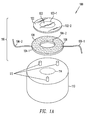
- mirror 102 is bonded to actuator 104.
- a self-centering vacuum chuck (not shown) to hold mirror 102 may be used in block 230.
- the chuck may be pre-cleaned with acetone and isopropanol wipe-downs in preparation for bonding mirror 102 to actuator 104.
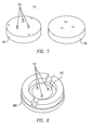
- a Teflon TM stand-off mold 701 may be placed over base mount 110 to form flexible posts 112 (block 240).
- An appropriate quantity of compliant, low out-gassing RTV TM compound may be mixed and injected into the mold 701 using, for example, a 14 gage stainless steel needle and syringe, and allowed to cure. After curing, a razor blade or knife may be used to cut away the spill-over material, so that each flexible post 112 is flat and flush with the top of mold 701. After curing, mold 701 may be lifted from the substrate without any twisting motion to avoid shearing the stand-offs.
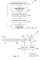
- the received intensity pattern is compared to a desired beam intensity pattern (block 1120).
- a controller may generate voltage commands to an amplifier based on the comparison of block 1120. For example, a differential mapping of the actual versus the desired beam pattern may be generated by the controller. The magnitude of the intensity differences in pixels of corresponding desired and actual pattern intensity distribution may be used to generate voltage vector value commands (i.e., polarity and amplitude).
- a laser cavity 1301 includes an output mirror 1320, a solid state laser gain medium comprised of one or more solid state laser rods 1310, and mirror-actuator subassembly 116.
- mirror 102 of sub-assembly 116 may be a primary high reflecting mirror in a stable or unstable resonator configuration.
- the associated control system of FIG. 12 comprising beam splitter 1230, sensor 1240, controller 1250 and voltage generator 1160 are not shown, but may be implemented by way of reference to FIG. 12 .
Landscapes
- Physics & Mathematics (AREA)
- General Physics & Mathematics (AREA)
- Optics & Photonics (AREA)
- Mechanical Light Control Or Optical Switches (AREA)
- Lasers (AREA)
- Optical Head (AREA)
Applications Claiming Priority (1)
| Application Number | Priority Date | Filing Date | Title |
|---|---|---|---|
| US11/760,562 US7473878B2 (en) | 2007-06-08 | 2007-06-08 | High power bimorph wave-front correction mirror |
Publications (2)
| Publication Number | Publication Date |
|---|---|
| EP2009480A2 true EP2009480A2 (de) | 2008-12-31 |
| EP2009480A3 EP2009480A3 (de) | 2010-03-10 |
Family
ID=39970851
Family Applications (1)
| Application Number | Title | Priority Date | Filing Date |
|---|---|---|---|
| EP08251940A Withdrawn EP2009480A3 (de) | 2007-06-08 | 2008-06-04 | Bimorpher Korrekturspiegel für Wellenfronten hoher Leistung |
Country Status (3)
| Country | Link |
|---|---|
| US (1) | US7473878B2 (de) |
| EP (1) | EP2009480A3 (de) |
| JP (1) | JP5308074B2 (de) |
Families Citing this family (3)
| Publication number | Priority date | Publication date | Assignee | Title |
|---|---|---|---|---|
| US9285516B2 (en) | 2010-08-02 | 2016-03-15 | Avinash Girish Bhardwaj | Actuator motion control mechanism for a concave mirror |
| WO2019206637A1 (en) | 2018-04-24 | 2019-10-31 | Asml Netherlands B.V. | Reflective optical element for a radiation beam |
| US20210036489A1 (en) * | 2019-08-02 | 2021-02-04 | Innolight Technology (Suzhou) Ltd. | Narrow linewidth external cavity laser and optical module |
Citations (3)
| Publication number | Priority date | Publication date | Assignee | Title |
|---|---|---|---|---|
| GB2128733A (en) * | 1982-10-14 | 1984-05-02 | Messerschmitt Boelkow Blohm | An adaptive optical system |
| JP2004333943A (ja) | 2003-05-08 | 2004-11-25 | Olympus Corp | 形状可変鏡および形状可変鏡を用いた光学装置 |
| WO2006098403A1 (ja) * | 2005-03-17 | 2006-09-21 | Brother Kogyo Kabushiki Kaisha | 光反射素子、光反射装置、波面曲率変調装置及び光走査型表示装置 |
Family Cites Families (18)
| Publication number | Priority date | Publication date | Assignee | Title |
|---|---|---|---|---|
| US3731103A (en) * | 1971-02-24 | 1973-05-01 | Hughes Aircraft Co | Adaptive arrays |
| US4438330A (en) * | 1982-03-01 | 1984-03-20 | Itek Corporation | Wavefront sensor employing a modulation reticle |
| US5026977A (en) * | 1989-04-05 | 1991-06-25 | The Charles Stark Draper Laboratory, Inc. | Wavefront sensing and correction with deformable mirror |
| US5016997A (en) * | 1990-05-15 | 1991-05-21 | The United States Of America As Represented By The United States Department Of Energy | Partially segmented deformable mirror |
| JP2893862B2 (ja) * | 1990-05-16 | 1999-05-24 | ソニー株式会社 | 固体レーザー発振器 |
| US5121405A (en) * | 1990-12-20 | 1992-06-09 | Coherent, Inc. | Alignment control system for lasers |
| US6192064B1 (en) * | 1997-07-01 | 2001-02-20 | Cymer, Inc. | Narrow band laser with fine wavelength control |
| JP3219072B2 (ja) * | 1999-02-17 | 2001-10-15 | 住友電気工業株式会社 | レーザビーム用形状可変鏡 |
| US6464364B2 (en) * | 2000-01-27 | 2002-10-15 | Aoptix Technologies, Inc. | Deformable curvature mirror |
| US6874897B2 (en) * | 2000-01-27 | 2005-04-05 | Aoptix Technologies, Inc. | Deformable curvature mirror with unipolar-wiring |
| US6452145B1 (en) * | 2000-01-27 | 2002-09-17 | Aoptix Technologies, Inc. | Method and apparatus for wavefront sensing |
| US6800988B1 (en) * | 2000-07-11 | 2004-10-05 | Technion Research & Development Foundation Ltd. | Voltage and light induced strains in porous crystalline materials and uses thereof |
| WO2004057407A1 (en) * | 2002-12-23 | 2004-07-08 | Bae Systems Plc | Deformable mirror |
| EP1576407A2 (de) * | 2002-12-23 | 2005-09-21 | BAE Systems PLC | Deformierbarer spiegel mit kühlvorrichtung |
| EP1676163A2 (de) * | 2003-10-20 | 2006-07-05 | BAE Systems PLC | Verbesserungen in bezug auf deformierbare spiegelhalter |
| US7229178B1 (en) * | 2004-12-20 | 2007-06-12 | Sandia Corporation | Variable focal length deformable mirror |
| JP2007025503A (ja) * | 2005-07-20 | 2007-02-01 | Topcon Corp | 可変形状ミラーの変形方法、その方法を用いた光学装置、及び眼底観察装置 |
| GB0526609D0 (en) | 2005-12-30 | 2006-02-08 | Imp College Innovations Ltd | A wavefront variation device |
-
2007
- 2007-06-08 US US11/760,562 patent/US7473878B2/en not_active Expired - Fee Related
-
2008
- 2008-06-04 EP EP08251940A patent/EP2009480A3/de not_active Withdrawn
- 2008-06-05 JP JP2008148165A patent/JP5308074B2/ja not_active Expired - Fee Related
Patent Citations (3)
| Publication number | Priority date | Publication date | Assignee | Title |
|---|---|---|---|---|
| GB2128733A (en) * | 1982-10-14 | 1984-05-02 | Messerschmitt Boelkow Blohm | An adaptive optical system |
| JP2004333943A (ja) | 2003-05-08 | 2004-11-25 | Olympus Corp | 形状可変鏡および形状可変鏡を用いた光学装置 |
| WO2006098403A1 (ja) * | 2005-03-17 | 2006-09-21 | Brother Kogyo Kabushiki Kaisha | 光反射素子、光反射装置、波面曲率変調装置及び光走査型表示装置 |
Non-Patent Citations (2)
| Title |
|---|
| LEE ET AL.: "A circular bimorph deformable mirror for circular/annulus/square laser beam compensation", JOURNAL OF THE OPTICAL SOCIETY OF KOREA, vol. 10, no. 1, 1 March 2006 (2006-03-01), pages 23 - 27, XP009128224, DOI: doi:10.3807/JOSK.2006.10.1.023 |
| LEE J H ET AL: "A circular bimorph deformable mirror for circular/annulus/square laser beam compensation", JOURNAL OF THE OPTICAL SOCIETY OF KOREA, OPTICAL SOCIETY OF KOREA, SEOUL, KR, vol. 10, no. 1, 1 March 2006 (2006-03-01), pages 23 - 27, XP009128224, ISSN: 1226-4776, DOI: 10.3807/JOSK.2006.10.1.023 * |
Also Published As
| Publication number | Publication date |
|---|---|
| JP2008304918A (ja) | 2008-12-18 |
| US7473878B2 (en) | 2009-01-06 |
| US20080302948A1 (en) | 2008-12-11 |
| JP5308074B2 (ja) | 2013-10-09 |
| EP2009480A3 (de) | 2010-03-10 |
Similar Documents
| Publication | Publication Date | Title |
|---|---|---|
| TWI691746B (zh) | 整合式光學總成、光學通信系統及製造整合式光學總成之方法 | |
| US7173713B2 (en) | Optical fiber sensors for harsh environments | |
| CN102576149B (zh) | 用于移动微型机械元件的致动器 | |
| JP3955438B2 (ja) | 湾曲した光学装置及びその作製方法 | |
| US20100202071A1 (en) | Deformable mirror | |
| US20070013914A1 (en) | Crystalline optical fiber sensors for harsh environments | |
| US8432661B2 (en) | Microstructural body and production method therefor | |
| CN115061114A (zh) | 激光雷达发射系统、扫描方法及晶圆级封装的器件 | |
| JP2005505000A (ja) | ビームステアリング光スイッチング素子 | |
| EP2856241B1 (de) | Modaler korrektorspiegel mit nachgiebigem antrieb für optische abweichungen | |
| WO2009134407A1 (en) | Optical package having deformable mirrors for focus compensation | |
| US7473878B2 (en) | High power bimorph wave-front correction mirror | |
| RU2623661C2 (ru) | Способ компенсации оптических аберраций с использованием деформируемого зеркала | |
| CN115480358B (zh) | 基于超声共振驱动的可变形反射镜 | |
| Verpoort et al. | Characterization of a miniaturized unimorph deformable mirror for high power cw-solid state lasers | |
| US6953254B2 (en) | Silicon wafer based macroscopic mirror for wide angle scanning applications | |
| CN118393677B (zh) | 一种高频叠堆式变形镜及其组装方法 | |
| WO2010127060A1 (en) | Folded lasers system | |
| Leitz et al. | Vibration and shock testing of a 50 mm aperture unimorph deformable mirror | |
| Helmbrecht et al. | Segmented MEMS deformable-mirror for wavefront correction | |
| TWI853543B (zh) | 對溫度不敏感的致動器與變形反射鏡 | |
| Helmbrecht et al. | Segmented MEMS deformable-mirror technology for space applications | |
| US12055788B2 (en) | Thermally actuated adaptive optics | |
| Neufeld et al. | The active primary mirror assembly for the SOAR telescope | |
| JP2008304918A5 (de) |
Legal Events
| Date | Code | Title | Description |
|---|---|---|---|
| PUAI | Public reference made under article 153(3) epc to a published international application that has entered the european phase |
Free format text: ORIGINAL CODE: 0009012 |
|
| 17P | Request for examination filed |
Effective date: 20080604 |
|
| AK | Designated contracting states |
Kind code of ref document: A2 Designated state(s): AT BE BG CH CY CZ DE DK EE ES FI FR GB GR HR HU IE IS IT LI LT LU LV MC MT NL NO PL PT RO SE SI SK TR |
|
| AX | Request for extension of the european patent |
Extension state: AL BA MK RS |
|
| PUAL | Search report despatched |
Free format text: ORIGINAL CODE: 0009013 |
|
| AK | Designated contracting states |
Kind code of ref document: A3 Designated state(s): AT BE BG CH CY CZ DE DK EE ES FI FR GB GR HR HU IE IS IT LI LT LU LV MC MT NL NO PL PT RO SE SI SK TR |
|
| AX | Request for extension of the european patent |
Extension state: AL BA MK RS |
|
| 17Q | First examination report despatched |
Effective date: 20101006 |
|
| AKX | Designation fees paid |
Designated state(s): AT BE BG CH CY CZ DE DK EE ES FI FR GB GR HR HU IE IS IT LI LT LU LV MC MT NL NO PL PT RO SE SI SK TR |
|
| STAA | Information on the status of an ep patent application or granted ep patent |
Free format text: STATUS: THE APPLICATION IS DEEMED TO BE WITHDRAWN |
|
| 18D | Application deemed to be withdrawn |
Effective date: 20181127 |