EP2009451A2 - Synchronsignalgenerator für Trimmungsausgleich eines Triebwerks - Google Patents
Synchronsignalgenerator für Trimmungsausgleich eines Triebwerks Download PDFInfo
- Publication number
- EP2009451A2 EP2009451A2 EP08158897A EP08158897A EP2009451A2 EP 2009451 A2 EP2009451 A2 EP 2009451A2 EP 08158897 A EP08158897 A EP 08158897A EP 08158897 A EP08158897 A EP 08158897A EP 2009451 A2 EP2009451 A2 EP 2009451A2
- Authority
- EP
- European Patent Office
- Prior art keywords
- generator
- spool
- synchronous signal
- signal generator
- output member
- Prior art date
- Legal status (The legal status is an assumption and is not a legal conclusion. Google has not performed a legal analysis and makes no representation as to the accuracy of the status listed.)
- Withdrawn
Links
- 230000001360 synchronised effect Effects 0.000 title claims abstract description 35
- 238000006243 chemical reaction Methods 0.000 claims abstract description 24
- 239000000523 sample Substances 0.000 claims description 6
- 230000005404 monopole Effects 0.000 claims description 3
- 230000003287 optical effect Effects 0.000 claims description 2
- 238000000034 method Methods 0.000 description 4
- 230000000712 assembly Effects 0.000 description 2
- 238000000429 assembly Methods 0.000 description 2
- 238000002485 combustion reaction Methods 0.000 description 2
- 230000000875 corresponding effect Effects 0.000 description 2
- 238000012544 monitoring process Methods 0.000 description 2
- 230000002596 correlated effect Effects 0.000 description 1
- 230000008878 coupling Effects 0.000 description 1
- 238000010168 coupling process Methods 0.000 description 1
- 238000005859 coupling reaction Methods 0.000 description 1
- 230000003247 decreasing effect Effects 0.000 description 1
- 239000000446 fuel Substances 0.000 description 1
- 230000006698 induction Effects 0.000 description 1
- 238000009434 installation Methods 0.000 description 1
- 239000002184 metal Substances 0.000 description 1
Images
Classifications
-
- F—MECHANICAL ENGINEERING; LIGHTING; HEATING; WEAPONS; BLASTING
- F02—COMBUSTION ENGINES; HOT-GAS OR COMBUSTION-PRODUCT ENGINE PLANTS
- F02C—GAS-TURBINE PLANTS; AIR INTAKES FOR JET-PROPULSION PLANTS; CONTROLLING FUEL SUPPLY IN AIR-BREATHING JET-PROPULSION PLANTS
- F02C7/00—Features, components parts, details or accessories, not provided for in, or of interest apart form groups F02C1/00 - F02C6/00; Air intakes for jet-propulsion plants
- F02C7/36—Power transmission arrangements between the different shafts of the gas turbine plant, or between the gas-turbine plant and the power user
Definitions
- the present invention relates generally to jet engines, and, more particularly, to a synchronous signal generator for use in the trim balancing of a multi-spool aircraft engine.
- a multi-spool jet engine typically includes a high pressure (HP) spool, which supports a high pressure compressor and a high pressure turbine.
- the high pressure compressor and the high pressure turbine may each include one or more bladed discs that extend radially outward from the HP shaft. As the HP shaft rotates, so too do the bladed discs. If the discs are not properly balanced (i.e., if the mass of the discs is not evenly distributed about the longitudinal axis of the HP shaft), vibrations may be produced as the HP shaft rotates.
- trim balancing involves the addition of weight to (e.g., the attachment of a counterweight) or the removal of weight from (e.g., grinding) the HP spool, the high pressure turbine, and/or the high pressure compressor.
- weight e.g., the attachment of a counterweight
- removal of weight from e.g., grinding
- multiple trial runs are performed. During each trial run, a test weight is added to the HP shaft at a chosen location and the resulting change in the magnitude of vibration is recorded. These changes in vibrations are then correlated to the rotational frequency of the HP spool during each trial run, and the location at which weight should be added or removed is eventually determined.
- Electronic signal generators have been developed that may derive the rotational frequency of the HP shaft by monitoring the rotation of a gear or other rotational body mechanically coupled to the HP shaft.
- a signal generator may include a controller having a sensor (e.g., a monopole or a proximity sensor), which is coupled to the controller and positioned adjacent the gear. As the gear rotates, each tooth of the gear passes by the sensor, which produces a corresponding timing pulse. The controller utilizes the signal provided by the sensor to derive the rotational frequency of the HP shaft during the trial run, which may then be utilized to trim balance the jet engine in the manner described above.
- the senor produces multiple timing pulses for each revolution of the HP shaft.
- the controller cannot determine which of these pulses represents a full revolution of the HP shaft through multiple trial runs.
- the timing pulse may become unsynchronized with the HP spool between engine starts during the trim balancing process. Due to this asynchronization, it may be difficult to determine the proper location at which weight should be added or removed without the performance of a significant number of trial runs; e.g., utilizing conventional trim balancing techniques and equipment, eight trial runs are typically necessary for two plan trim balancing.
- the engine is shut-down, dissembled, reassembled, and then re-activated. The performance of multiple trial runs is thus time consuming and costly.
- each trial run results in additional wear to the jet engine consequently decreasing the engine's life and overall value.
- a synchronous signal generator for use in conjunction with an aircraft engine having a spool and an engine output shaft driven by the spool.
- the synchronous signal generator includes a generator housing, a generator output member rotatably mounted in the generator housing, a once-per-revolution timing mark on the generator output member, and conversion gearing disposed within the housing and configured to couple the engine output shaft to the generator output member.
- the conversion gearing rotates the generator output member at substantially the same rotational frequency as the spool when the conversion gearing is coupled to the engine output shaft.
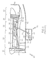
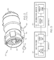
- FIGs. 1 and 2 are cross-sectional and isometric views, respectively, of a conventional multi-spool jet engine including an accessory gearbox;
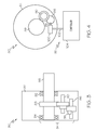
- FIGs. 3 and 4 are side cross-sectional and rear cross-sectionals, respectively, of a simplified synchronous signal generator in accordance with a first exemplary embodiment of the present invention.
- FIG. 5 is a functional schematic of the exemplary synchronous signal generator shown in FIGs. 3 and 4 coupled to the multi-spool jet engine shown in FIGs. 1 and 2 .
- FIGs. 1 and 2 are cross-section and isometric views of a multi-spool jet engine 20 of the type conventionally deployed on an aircraft.
- multi-spool jet engine 20 is a three spool turbofan gas turbine engine.
- jet engine 20 may have an intake section 22, a compressor section 24, a combustion section 26, a turbine section 28, and an exhaust section 30.
- Intake section 22 includes a fan 32, which is mounted in a fan case 34.
- Compressor section 24 includes one or more compressors (e.g., an intermediate pressure (IP) compressor 36 and a high pressure (HP) compressor 38), and turbine section 28 includes one or more turbines (e.g., an HP turbine 40, an IP turbine 42, and a low pressure (LP) turbine 44), which may be disposed in axial flow series.
- HP compressor 38 and HP turbine 40 are mounted on opposite ends of an HP shaft or spool 46;
- IP compressor 36 and IP turbine 42 are mounted on opposite ends of IP spool 48;
- fan 32 and LP turbine 44 are mounted on opposite ends of a LP spool 50.
- HP spool 46, IP spool 48, and LP spool 50 are substantially co-axial. That is, LP spool 50 may extend through a longitudinal channel provided through IP spool 48, and IP spool 48 may extend through a longitudinal channel provided through HP spool 46.
- Jet engine 20 is further provided with an engine output shaft, which may be any body that is rotatably coupled to HP spool 46.
- the engine output shaft may be a gearbox output shaft contained within a conventional accessory gearbox.
- Accessory gearbox 60 includes a gearbox housing 62, which contains a gearbox input shaft 64 and at least one gearbox output shaft 66 (e.g., a female spline).
- Gearbox output shaft 66 is rotationally coupled to gearbox input shaft 64, which is rotationally coupled to HP spool 46 by way of a tower shaft 70.
- gearbox output shaft 66 thus rotates in conjunction with HP spool 46.
- the rotational frequency of gearbox output shaft 66 will not be equivalent to that of HP spool 46; instead, relative to the rotational frequency of HP spool 46, the rotational frequency of gearbox output shaft 66 will be reduced by the gear ratio from HP spool 46 to gearbox output shaft 66. For example, if the gear ratio is 3.5:1, HP spool 46 will rotate three and a half revolutions for each revolution of gearbox output shaft 66.
- At least one accessory flange or pad 72 is provided on the exterior of gearbox housing 62.
- an accessory 76 e.g., a generator, a hydraulic pump, etc.
- Accessory 76 includes a rotatable shaft 78 (e.g., a male spline), which may be inserted into gearbox housing 62 through an aperture 74 provided in gearbox housing 62.
- rotatable shaft 78 mechanically engages gearbox output shaft 66.
- HP spool 46 drives gearbox output shaft 66, which, in turn, drives rotatable shaft 78 of accessory 76.
- HP turbine 40 and HP compressor 38 each include one or more bladed discs, which are fixedly mounted on HP spool 46 and rotate therewith. If these bladed discs are not properly balanced, vibrations may be produced as HP spool 46 rotates. To minimize or eliminate these vibrations, the bladed discs forming HP turbine 40 and those forming compressor 38 may be trim balanced by adding or removing weight from HP turbine 40, HP compressor 38, and/or HP spool 46. As explained above, the vibrations produced by engine 20 may be measured during a number of trial runs and then compared to the rotational frequency of HP spool 46 during each trial run to determine the locations at which weight should be added or removed.
- timing pulse indicative of the rotational frequency of an HP spool during a given trial run
- the timing pulse becomes asynchronous between successive trial runs.
- signal generator that produces a signal indicative of the rotational frequency and position of HP spool 46 that remains synchronized with HP spool 46 over an infinite number of trial runs and thereby facilitates the trim balancing process.
- FIGs. 3 and 4 are simplified side cross-sectional and rear cross-sectional views, respectively, of a synchronous signal generator 80 in accordance with a first exemplary embodiment.
- Signal generator 80 includes a housing 82, which houses conversion gearing 84 (e.g., a gear train) and a generator output member 86 (e.g., a geared shaft).
- Generator output member 86 is mechanically coupled to, and thus rotates in conjunction with, conversion gearing 84.
- Conversion gearing 84 includes one or more rotational bodies suitable for indirectly coupling generator output member 86 to HP spool 46; e.g., conversion gearing 84 may be a gear train, which is configured to be mechanically coupled to gearbox output shaft 66 in the manner described below.
- conversion gearing 84 includes first and second geared shafts 88 and 90.
- Geared shafts 88 and 90 are each rotatably mounted in housing 82.
- a first bearing assembly 92 e.g., an annular roller bearing
- a second bearing assembly 94 e.g., an annular ball bearing
- Similar bearing assemblies may also be disposed around geared shaft 90 and/or generator output member 86, although such bearing assemblies are not shown in FIGs. 3 and 4 for clarity.
- Conversion gearing 84 is configured to be mechanically coupled to HP spool 46 via accessory gearbox 60 ( FIG. 2 ).
- geared shaft 88 may include a threaded or toothed protruding portion 96 (e.g., a male or female spline) that may extend from housing 82.
- Synchronous signal generator 80 may be mounted (e.g., bolted) onto accessory pad 72 ( FIGs. 1 and 2 ) prior to installation of (or after the removal of) accessory 76 ( FIG. 2 ).
- protruding portion 96 extends through aperture 74 ( FIG. 1 ) and mechanically engages gearbox output shaft 66 (e.g., a female or male spline).
- gearbox output shaft 66 e.g., a female or male spline
- Synchronous signal generator 80 is configured such that the rotational frequency of generator output member 86 is substantially equivalent to that of HP spool 46. This point is further illustrated in FIG. 5 , which is a functional schematic of signal generator 80 coupled to gearbox output shaft 66 of multi-spool engine 20. As stated above, the rotational frequency of gearbox output shaft 66 (RF gearbox_output_shaft ) is related to the rotational frequency of HP spool 46. In particular, RF gearbox_output_shaft is a function of the gear ratio taken from HP spool 46 to gearbox output shaft 66. This gear ratio is determined by the design of jet engine 20 and may vary from engine to engine.
- Conversion gearing 84 is configured such that the gear ratio taken from gearbox output shaft 66 to generator output member 86 is substantially the inverse of the gear ratio taken from HP spool 46 to gearbox output shaft 66. That is, conversion gearing 84 is configured to produce a gearbox-ouput-shaft-to-generator-ouput-member gear ratio of substantially Y:X.
- conversion gearing 84 will preferably be configured to produce a gearbox-output-shaft-to-generator-output-member gear ratio of substantially 1:3.2.
- conversion gearing 84 may be configured such that generator output member 86 rotates at substantially the same frequency as does HP spool 46 (i.e., the gear ratio taken from HP spool 46 to generator output member 86 is substantially X:X or 1:1).
- a once-per-revolution timing mark 98 is provided on generator output member 86.
- Once-per-revolution timing mark 98 may be any element that may be monitored to produce a timing signal indicating the rotational frequency of output member 86 and, therefore, of HP spool 46.
- once-per-revolution timing mark 98 may be a topographical feature formed on the shaft of generator output member 86, such as a cavity (e.g., a notch) or a projection (e.g., a keyway).
- once-per-revolution timing mark 98 may be an optical feature, such as a surface (e.g., reflective tape) having unique light-absorbing or reflecting characteristics relative to the surrounding portions of output member 86. As shown in FIG.
- timing mark 98 may be monitored electronically by a sensor system 99 disposed proximate generator output member 86.
- sensor system 99 includes a probe or sensor 100, which may be coupled by way of connector 102 to a sensor controller 104.
- Sensor 100 may take the form of any electronic device capable of monitoring the movement of timing mark 98 (e.g., identifying when timing mark 98 passes by sensor 100).
- timing mark 98 is a topographical feature formed in or on a metal body
- sensor 100 may be an induction probe (e.g., monopole or a proximity probe).
- timing mark 98 is a strip of reflective tape
- sensor 100 may be a light source (e.g., a laser, a light emitting diode, etc.) and a light sensor.
- once-per-revolution timing mark 98 and sensor 100 cooperate to produce a timing pulse corresponding to each revolution of generator output member 86 and, therefore, to each revolution of HP spool 46.
- the timing pulses produced by sensor 100 may be utilized by controller 104 or other conventional vibration measuring equipment to determine the location at which weight should be added or removed from HP turbine 40, HP compressor 38, and/or HP spool 46.
- conversion gearing 84 substantially matches the rotational frequency of generator output member 66 to that of HP spool 46. It should also be appreciated that generator output member 66 is mechanically locked to HP spool 46 (e.g., even if HP spool 46 were to be manually moved by a technician inspecting HP turbine 40, generator output shaft 66 will move accordingly). For these reasons, generator output member 66, and thus the timing pulses produced by sensor 100, will remain synchronized with HP spool 46 for an infinite number of trial runs.
- jet engine 20 may be trim balanced utilizing a minimum number of trial runs (e.g., one plane trim balancing may be performed with a single trial run, and two plane trim balancing may be performed with a total of two trial runs).
- Synchronous signal generator 80 thus facilitates the trim-balancing of high speed (or intermediate speed) shafts that do not have a synchronous timing mark available.
- the signal generator may be incorporated into the engine.
- the synchronous signal generator may be configured to permit the gear ratio of the conversion gearing to be manipulated (e.g., the conversion gearing may be interchangeable).
- the synchronous signal generator may be utilized to trim balance any suitable spool, including, for example, an intermediate pressure spool (e.g., IP spool 50 shown in FIG. 1 ).
Landscapes
- Engineering & Computer Science (AREA)
- Chemical & Material Sciences (AREA)
- Combustion & Propulsion (AREA)
- Mechanical Engineering (AREA)
- General Engineering & Computer Science (AREA)
- Turbine Rotor Nozzle Sealing (AREA)
- Retarders (AREA)
- Control Of Turbines (AREA)
Applications Claiming Priority (1)
| Application Number | Priority Date | Filing Date | Title |
|---|---|---|---|
| US11/769,515 US20090060717A1 (en) | 2007-06-27 | 2007-06-27 | Synchronous signal generator for trim balancing of jet engine |
Publications (1)
| Publication Number | Publication Date |
|---|---|
| EP2009451A2 true EP2009451A2 (de) | 2008-12-31 |
Family
ID=39828949
Family Applications (1)
| Application Number | Title | Priority Date | Filing Date |
|---|---|---|---|
| EP08158897A Withdrawn EP2009451A2 (de) | 2007-06-27 | 2008-06-24 | Synchronsignalgenerator für Trimmungsausgleich eines Triebwerks |
Country Status (3)
| Country | Link |
|---|---|
| US (1) | US20090060717A1 (de) |
| EP (1) | EP2009451A2 (de) |
| CA (1) | CA2636407A1 (de) |
Families Citing this family (4)
| Publication number | Priority date | Publication date | Assignee | Title |
|---|---|---|---|---|
| DE102010020024B4 (de) | 2010-05-10 | 2016-05-25 | Rolls-Royce Deutschland Ltd & Co Kg | Triebwerkssynchronisierverfahren |
| US20130003071A1 (en) * | 2011-06-30 | 2013-01-03 | Catch the Wind, Inc. | System and Method of In Situ Wind Turbine Blade Monitoring |
| US10087761B2 (en) * | 2013-12-20 | 2018-10-02 | Pratt & Whitney Canada Corp. | Devices and methods for balancing a high-pressure spool of a gas turbine engine |
| CN111579205B (zh) * | 2020-06-23 | 2024-05-28 | 中国空气动力研究与发展中心高速空气动力研究所 | 一种喷流天平 |
Family Cites Families (11)
| Publication number | Priority date | Publication date | Assignee | Title |
|---|---|---|---|---|
| US3188627A (en) * | 1962-01-30 | 1965-06-08 | Itt | Shaft angle encoding apparatus |
| US3358279A (en) * | 1963-09-19 | 1967-12-12 | Industrial Nucleonics Corp | Position indicating apparatus |
| US3601585A (en) * | 1968-09-18 | 1971-08-24 | Dan B Paulsen | Method and apparatus for totalizing materials from construction drawings |
| US4074196A (en) * | 1976-08-02 | 1978-02-14 | Webster Douglas G | Speedometer and odometer apparatus |
| JPS54148578A (en) * | 1978-04-18 | 1979-11-20 | Nec Corp | Rotating direction detector |
| US4687952A (en) * | 1984-02-06 | 1987-08-18 | United Technologies Corporation | Dynamic angular position sensor for a reference gear tooth |
| JPH02208513A (ja) * | 1989-02-08 | 1990-08-20 | Mitsubishi Electric Corp | ロータリーエンコーダ |
| US5140856A (en) * | 1990-12-03 | 1992-08-25 | Dynamic Rotor Balancing, Inc. | In situ balancing of wind turbines |
| US5144233A (en) * | 1991-08-30 | 1992-09-01 | Delco Electronics Corporation | Crankshaft angular position voltage developing apparatus having adaptive control and diode control |
| US6414481B1 (en) * | 2000-09-27 | 2002-07-02 | Brunswick Corporation | Portable tester and calibration apparatus for a speed or position sensor |
| FR2848358B1 (fr) * | 2002-12-04 | 2005-03-18 | Roulements Soc Nouvelle | Systeme d'actionnement comprenant un capteur numerique de position |
-
2007
- 2007-06-27 US US11/769,515 patent/US20090060717A1/en not_active Abandoned
-
2008
- 2008-06-24 EP EP08158897A patent/EP2009451A2/de not_active Withdrawn
- 2008-06-26 CA CA002636407A patent/CA2636407A1/en not_active Abandoned
Also Published As
| Publication number | Publication date |
|---|---|
| US20090060717A1 (en) | 2009-03-05 |
| CA2636407A1 (en) | 2008-12-27 |
Similar Documents
| Publication | Publication Date | Title |
|---|---|---|
| EP2898205B1 (de) | Hilfsgetriebe für gasturbinenmotor | |
| US11686253B2 (en) | Through-flow gas turbine engine with electric motor and electric generator | |
| EP3361229B1 (de) | System und verfahren zur rotorblattüberwachung | |
| US10393027B2 (en) | Gas turbine engine shaft architecture and associated method of disassembly | |
| EP3273031B1 (de) | Gasturbinenmotorwellenarchitektur und zugehöriges demontageverfahren | |
| EP3910174B1 (de) | Gegenstromgasturbinentriebwerk mit elektromotor | |
| CA2872119C (en) | Devices and methods for balancing a high-pressure spool of a gas turbine engine | |
| EP4257806A1 (de) | Verfahren und system zur überwachung eines zustands einer komponente eines gasturbinenmotors | |
| US10316745B2 (en) | Turbomachine fan clutch | |
| EP3683410A2 (de) | Erkennen eines objektaufprallereignisses | |
| CA2970978A1 (en) | Gas turbine engine shaft architecture and associated method of disassembly | |
| EP3699414A1 (de) | Gasturbinentriebwerk mit hilfsgetriebe | |
| US20090060717A1 (en) | Synchronous signal generator for trim balancing of jet engine | |
| EP3502442A1 (de) | Getriebe mit konzentrischer leistungsabnahme | |
| US12297743B2 (en) | Gas turbine engine having a sensor assembly to detect torsional vibration | |
| EP4400693A1 (de) | Rechnerischer ausgleich einer rotierenden struktur | |
| EP4553309A1 (de) | Turbinenmotorzubehörsystem mit mehreren getrieben |
Legal Events
| Date | Code | Title | Description |
|---|---|---|---|
| PUAI | Public reference made under article 153(3) epc to a published international application that has entered the european phase |
Free format text: ORIGINAL CODE: 0009012 |
|
| 17P | Request for examination filed |
Effective date: 20080624 |
|
| AK | Designated contracting states |
Kind code of ref document: A2 Designated state(s): AT BE BG CH CY CZ DE DK EE ES FI FR GB GR HR HU IE IS IT LI LT LU LV MC MT NL NO PL PT RO SE SI SK TR |
|
| AX | Request for extension of the european patent |
Extension state: AL BA MK RS |
|
| STAA | Information on the status of an ep patent application or granted ep patent |
Free format text: STATUS: THE APPLICATION HAS BEEN WITHDRAWN |
|
| 18W | Application withdrawn |
Effective date: 20091002 |