EP2009251A2 - Annular turbine casing of a gas turbine engine and corresponding turbine assembly - Google Patents
Annular turbine casing of a gas turbine engine and corresponding turbine assembly Download PDFInfo
- Publication number
- EP2009251A2 EP2009251A2 EP08158591A EP08158591A EP2009251A2 EP 2009251 A2 EP2009251 A2 EP 2009251A2 EP 08158591 A EP08158591 A EP 08158591A EP 08158591 A EP08158591 A EP 08158591A EP 2009251 A2 EP2009251 A2 EP 2009251A2
- Authority
- EP
- European Patent Office
- Prior art keywords
- annular
- aft
- annular shell
- axially
- flange
- Prior art date
- Legal status (The legal status is an assumption and is not a legal conclusion. Google has not performed a legal analysis and makes no representation as to the accuracy of the status listed.)
- Granted
Links
Images

Classifications
-
- F—MECHANICAL ENGINEERING; LIGHTING; HEATING; WEAPONS; BLASTING
- F01—MACHINES OR ENGINES IN GENERAL; ENGINE PLANTS IN GENERAL; STEAM ENGINES
- F01D—NON-POSITIVE DISPLACEMENT MACHINES OR ENGINES, e.g. STEAM TURBINES
- F01D25/00—Component parts, details, or accessories, not provided for in, or of interest apart from, other groups
- F01D25/08—Cooling; Heating; Heat-insulation
- F01D25/14—Casings modified therefor
-
- F—MECHANICAL ENGINEERING; LIGHTING; HEATING; WEAPONS; BLASTING
- F01—MACHINES OR ENGINES IN GENERAL; ENGINE PLANTS IN GENERAL; STEAM ENGINES
- F01D—NON-POSITIVE DISPLACEMENT MACHINES OR ENGINES, e.g. STEAM TURBINES
- F01D25/00—Component parts, details, or accessories, not provided for in, or of interest apart from, other groups
- F01D25/24—Casings; Casing parts, e.g. diaphragms, casing fastenings
- F01D25/246—Fastening of diaphragms or stator-rings
-
- F—MECHANICAL ENGINEERING; LIGHTING; HEATING; WEAPONS; BLASTING
- F05—INDEXING SCHEMES RELATING TO ENGINES OR PUMPS IN VARIOUS SUBCLASSES OF CLASSES F01-F04
- F05D—INDEXING SCHEME FOR ASPECTS RELATING TO NON-POSITIVE-DISPLACEMENT MACHINES OR ENGINES, GAS-TURBINES OR JET-PROPULSION PLANTS
- F05D2260/00—Function
- F05D2260/20—Heat transfer, e.g. cooling
- F05D2260/201—Heat transfer, e.g. cooling by impingement of a fluid
-
- F—MECHANICAL ENGINEERING; LIGHTING; HEATING; WEAPONS; BLASTING
- F05—INDEXING SCHEMES RELATING TO ENGINES OR PUMPS IN VARIOUS SUBCLASSES OF CLASSES F01-F04
- F05D—INDEXING SCHEME FOR ASPECTS RELATING TO NON-POSITIVE-DISPLACEMENT MACHINES OR ENGINES, GAS-TURBINES OR JET-PROPULSION PLANTS
- F05D2270/00—Control
- F05D2270/40—Type of control system
- F05D2270/44—Type of control system active, predictive, or anticipative
-
- Y—GENERAL TAGGING OF NEW TECHNOLOGICAL DEVELOPMENTS; GENERAL TAGGING OF CROSS-SECTIONAL TECHNOLOGIES SPANNING OVER SEVERAL SECTIONS OF THE IPC; TECHNICAL SUBJECTS COVERED BY FORMER USPC CROSS-REFERENCE ART COLLECTIONS [XRACs] AND DIGESTS
- Y02—TECHNOLOGIES OR APPLICATIONS FOR MITIGATION OR ADAPTATION AGAINST CLIMATE CHANGE
- Y02T—CLIMATE CHANGE MITIGATION TECHNOLOGIES RELATED TO TRANSPORTATION
- Y02T50/00—Aeronautics or air transport
- Y02T50/60—Efficient propulsion technologies, e.g. for aircraft
Landscapes
- Engineering & Computer Science (AREA)
- Mechanical Engineering (AREA)
- General Engineering & Computer Science (AREA)
- Turbine Rotor Nozzle Sealing (AREA)
Abstract
Description
- This invention relates to thermal control of gas turbine engine rings such as flanges or pseudo-flanges as might be found in turbine tip clearance control apparatus and, more particularly, to thermal control surfaces upon which thermal control fluid is impinged on gas turbine engine rings and/or flanges.
- Engine performance parameters such as thrust, specific fuel consumption (SFC), and exhaust gas temperature (EGT) margin are strongly dependent upon clearances between turbine blade tips and static seals or shrouds surrounding the blade tips. Active clearance control is a well known method to modulate a flow of cool or relatively hot air, generally referred to as thermal control air, from the engine fan and/or compressor and spray it on high and low pressure turbine casings to shrink the casings relative to the high and low pressure turbine blade tips during a flight. The air may be flowed to or sprayed or impinged on other static structures used to support the shrouds or seals around the blade tips such as flanges or pseudo-flanges which function as thermal control rings. It is highly desirable to be able to increase heat transfer between the thermal control air and the thermal control rings as compared to previous designs and, thus, make more efficient use of the thermal control air.
- Typically, in current ACC designs, fan and/or compressor air is used to impinge on the HPT case pseudo-flanges to control case deflection at the scheduled time during the flight to achieve a desired tip clearance. The pseudo-flanges support shrouds surrounding turbine blade tips and thus heating or cooling the pseudo-flanges moves the shroud radially outwardly or inwardly respectively thus controlling tip clearances between the shrouds and the turbine blade tips. The spent air flow from forward flange or pseudo-flange impingement interferes with impingement flow on an aft pseudo-flange, thus, the heat transfer on the aft pseudo-flange is reduced, perhaps by half or more. Thus, a more effective design to improve heat transfer on the aft pseudo flange is desirable.
- A gas turbine engine annular turbine casing includes an annular shell circumscribed about a central axis, axially spaced apart forward and aft flanges extending radially outwardly from the annular shell, and forward and aft case hooks depending radially inwardly from the annular shell of the casing. A circular row of axially extending cooling holes disposed through the aft flange, circumscribing the central axis, and radially located between the outer diameter of the aft flange and the annular shell.
- In an exemplary embodiment of the turbine casing, the forward and aft case hooks are located axially near or at the forward and aft flanges respectively. A rear flange may extend radially outwardly from a rear end of the annular shell and a rear case hook may depend radially inwardly from the annular shell. The rear case hook being axially located at or near the rear end of the annular shell. In another exemplary embodiment of the turbine casing, the aft flange has an annular radially outwardly facing axially curved surface at an outer diameter of the aft flange and the forward and rear flanges have radially outwardly facing cylindrical surfaces at outer diameters of the forward and rear flanges. The axially curved surface may be a semi-spherical surface having a radius of curvature and the radius of curvature has an origin on the central axis.
- The annular turbine casing may be incorporated in a gas turbine engine turbine assembly having a shroud assembly depending radially inwardly from the turbine casing and connected to the forward and aft case hooks. An exemplary embodiment of the shroud assembly includes a plurality of arcuate shroud segments coupled to segmented shroud hangers. The shroud hangers are supported by segmented shroud supports depending radially inwardly from the turbine casing and forward and aft ends of the shroud support are supported by the forward and aft case hooks respectively.
- Another exemplary embodiment of the turbine assembly includes an annular manifold circumscribing the central axis and spaced radially outwardly of the annular shell forming an annular space between the manifold and the annular shell. Impingement holes may be disposed through the manifold and located for impinging cooling air radially inwardly on to the axially curved surface and radially outwardly facing cylindrical surfaces at of the forward and rear flanges.
- The foregoing aspects and other features of the invention are explained in the following description of embodiments provided by way of example only taken in connection with the accompanying drawings where:
-
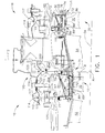
FIG. 1 is a schematical cross-sectional view illustration of a portion of an aircraft gas turbine engine clearance control system including a flange supporting a turbine shroud assembly. -
FIG. 2 is an enlarged schematical cross-sectional view illustration of the flange illustrated inFIG. 1 . - Schematically illustrated in cross-section in
FIGS. 1 and2 is an exemplary embodiment of aturbine assembly 10 used as part of aclearance control system 100 for an aircraft gas turbine engine which facilitates controllingblade tip clearance 88 during engine operation. Theclearance control system 100 is more fully described inUS Patent No. 7,165,937 by Dong et al. issued January 23, 2007 and incorporated herein by reference. The exemplary embodiment of theclearance control system 100 illustrated herein is for afirst stage 12 of ahigh pressure turbine 18. Asecond stage 20 of thehigh pressure turbine 18 is downstream and aft of thefirst stage 12 of thehigh pressure turbine 18. First and secondstage turbine nozzles second stages high pressure turbine 18. Annular high pressure turbine first and secondstage shroud assemblies central axis 34 which typically coincides with an engine centerline. Each of the shroud assemblies circumscribes a row of highpressure turbine blades 70 and depends radially inwardly from a surroundingturbine casing 75. - The first
stage shroud assembly 71 includes a plurality ofarcuate shroud segments 72 coupled to segmentedshroud hangers 74. Theshroud hangers 74 are supported by segmented shroud supports 30 which depend radially inwardly fromturbine casing 75. Theshroud hangers 74 are connected to the shroud supports 30 and are held in place by C-clip 76. With regards to the firststage shroud assembly 71, axially spaced apart forward andaft flanges annular shell 80 of thecasing 75. Arear flange 118 extends radially outwardly from arear end 90 of theannular shell 80 and arear case hook 66 depends radially inwardly from theannular shell 80 and is axially located at or near therear end 90 of theannular shell 80. Forward and aft ends 77, 79 of theshroud support 30 of the firststage shroud assembly 71 are supported by forward andaft case hooks annular shell 80 of thecasing 75. The forward, aft, andrear case hooks rear flanges -
Adjacent shroud segments 72 are coupled together to form the first and secondstage shroud assemblies turbine blades 70 about thecentral axis 34. Eachshroud segment 72 includes a radially outer surface 84 and an opposite radiallyinner surface 86. Theblade tip clearance 88 is defined between shroudinner surface 86 andtips 89 of theturbine blades 70. More specifically, theblade tip clearance 88 is defined as the distance betweenturbine blade tips 89 and an inner surface ofturbine shroud segment 72. Thus, whenturbine casing 75 and in particular forward andaft flanges stage shroud assembly 71 and the plurality ofarcuate shroud segments 72 of the firststage shroud assembly 71. In the exemplary embodiment,clearance control system 100 facilitates controlling theblade tip clearance 88 betweenrotor blade tips 89 and shroudinner surfaces 86.Clearance control system 100 is coupled in flow communication to a cooling air supply source via anannular manifold 114 circumscribed about thecentral axis 34. Themanifold 114 is spaced radially outwardly of theannular shell 80 and anannular space 119 is disposed therebetween. -
Cooling air 112 radially inwardly exits manifold 114 throughimpingement holes 117 and impinges on an annular radially outwardly facing and radially outer most axiallycurved surface 120 of theaft flange 126 extending radially outwardly from theannular shell 80 of theturbine casing 75. The axiallycurved surface 120 at anouter diameter 123 of theaft flange 126 is circumscribed about a radius of curvature R having anorigin 81 on thecentral axis 34 and extending from the origin to theouter diameter 123 of theaft flange 126. The axiallycurved surface 120 illustrated herein is a semi-spherical surface but other curved surfaces of revolution about thecentral axis 34 may be used. The semi-spherical axiallycurved surface 120 has the same radius of curvature R having anorigin 81 on thecentral axis 34 and extending from the origin to theouter diameter 123 of theaft flange 126. - The axially
curved surface 120 is an impingement surface and takes advantage of the Coanda effect which states that air tends to flow along a curved surface. The Coanda effect has an even greater effect on heat transfer for a spherically curved surface. The curved surface as opposed to previously used cylindrical surfaces, such as those illustrated inUS Patent No. 7,165,937 , provide greater heat transfer by making use of the Coanda effect.Cooling air 112 also exits manifold 114 to impinge on a radially outwardly facing and radially outer mostcylindrical surfaces 122 of the forward andrear flanges - The
cooling air 112 that has impinged on thecylindrical surfaces 122 of theforward flange 125 and the axiallycurved surface 120 of theaft flange 126 is referred to herein as spentair 116 which is exhausted from anannular space 119 between themanifold 114 and theannular shell 80 of theturbine casing 75. A circular row of axially extendingcooling holes 200 disposed through the aft flange 126 (a pseudo-flange) circumscribes thecentral axis 34 and are radially located between theouter diameter 123 of theaft flange 126 and theannular shell 80. Thecooling holes 200 allow thespent air 116 to flow into anaft cavity 202 between the aft andrear flanges - The
spent air 116 is relatively cool compared to a case temperature of theannular shell 80 and theturbine casing 75. Theaft flange 126 is cooled by thespent air 116 flowing through thecooling holes 200. This causes flows in aforward cavity 204 between the forward andaft flanges aft cavity 202 to be more active and enhance heat transfer between theimpingement cooling air 200 and thespent air 116 and the flanges, theannular shell 80, and theturbine casing 75. The enhanced heat transfer provides better cooling effectiveness between the air flows and the flanges, theannular shell 80, and theturbine casing 75 which leads to a better control of the radial growth and shrinkage to achieve a desiredblade tip clearance 88. - The
aft flange 126 is also referred to as a pseudo-flange in the aircraft gas turbine engine industry. The cooing air supply source may be any cooling air supply source that enablesclearance control system 100 to function as described herein, such as, but not limited to, fan air, an intermediate stage and/or a discharge stage of a compressor. In the exemplary embodiment, coolingair 112 is bled from an intermediate stage of a compressor for second stage turbine nozzle and shroud cooling. Theclearance control system 100 is used to minimize the radialblade tip clearance 88 between theblade tips 89 and theshroud segments 72, particularly during cruise operation of the engine. - It is well known in the industry that small turbine blade tip clearances provide lower operational specific fuel consumption (SFC) and, thus, large fuel savings. The forward and aft flanges are provided to more effectively control blade tip clearance CL with a minimal amount of time lag and thermal control (cooling or heating depending on operating conditions) air flow. The forward and flanges are attached to or otherwise associated with the
annular shell 80 of theturbine casing 75 and may be integral with the respective casing or shell of the casing (as illustrated inFIG. 2 ), bolted to or otherwise fastened to the shell or mechanically isolated from but in sealing engagement with the shell. The flanges may also be bolted flanges such as those found at the end of some casing shells. The flanges serve as thermal control rings provide thermal control mass to more effectively move theshroud segments 72 radially inwardly (and outwardly if so designed) to adjust the blade tip clearances. - While there have been described herein what are considered to be preferred and exemplary embodiments of the present invention, other modifications of the invention shall be apparent to those skilled in the art from the teachings herein and, it is therefore, desired to be secured in the appended claims all such modifications as fall within the true spirit and scope of the invention. Accordingly, what is desired to be secured by Letters Patent is the invention as defined and differentiated in the following claims.
Claims (14)
- A gas turbine engine annular turbine casing (75) comprising:an annular shell (80) circumscribed about a central axis (34),axially spaced apart forward and aft flanges (125, 126) extending radially outwardly from the annular shell (80),forward and aft case hooks (67, 69) depending radially inwardly from the annular shell (80) of the casing (75), anda circular row of axially extending cooling holes (200) disposed through the aft flange (126) circumscribing the central axis (34) and radially located between the outer diameter (123) of the aft flange (126) and the annular shell (80).
- A gas turbine engine annular turbine casing (75) as claimed in Claim 1 further comprising the forward and aft case hooks (67, 69) being located axially near or at the forward and aft flanges (125, 126) respectively.
- A gas turbine engine annular turbine casing (75) as claimed in Claim 2 further comprising:a rear flange (118) extending radially outwardly from a rear end (81) of the annular shell (80),a rear case hook (66) depending radially inwardly from the annular shell (80), andthe rear case hook (66) being axially located at or near the rear end (81) of the annular shell (80).
- A gas turbine engine annular turbine casing (75) as claimed in any one of the preceding Claims further comprising radially outwardly facing cylindrical surfaces (122) at outer diameters (123) of the forward and rear flanges (125, 118) and a radially outwardly facing axially curved annular surface (120) of the aft flange (126) at an outer diameter (123) of the aft flange (126).
- A gas turbine engine annular turbine casing (75) as claimed in any one of the preceding Claims further comprising:a rear flange (118) extending radially outwardly from a rear end (81) of the annular shell (80),a rear case hook (66) depending radially inwardly from the annular shell (80), andthe rear case hook (66) being axially located at or near the rear end (81) of the annular shell (80).
- A gas turbine engine annular turbine casing (75) as claimed in Claim 4 further comprising the axially curved surface (120) being a semi-spherical surface having a radius of curvature (R) and the radius of curvature (R) having an origin (81) on the central axis (34).
- A gas turbine engine annular turbine casing as claimed in claim 6 further comprising the forward and aft case hooks being located axially near or at the forward and aft flanges respectively.
- a gas turbine engine annular turbine casing as claimed in Claim 7 further comprising:a rear flange extending radially outwardly from a rear end of the annular shell,the rear case hook depending radially inwardly from the annular shell, andThe rear case hook being axially located at or near the rear end of the annular shell.
- A gas turbine engine turbine assembly (10) comprising:an annular turbine casing (75) having an annular shell (80) circumscribed about a central axis (34),axially spaced apart forward and aft flanges (125, 126) extending radially outwardly from the annular shell (80),forward and aft case hooks (67, 69) depending radially inwardly from the annular shell (80) of the casing (75),a shroud assembly (71) depending radially inwardly from the turbine casing (75) and being connected to the forward and aft case hooks (67, 69), anda circular row of axially extending cooling holes (200) disposed through the aft flange (126) circumscribing the central axis (34) and radially located between the outer diameter (123) of the aft flange (126) and the annular shell (80).
- A turbine assembly (10) as claimed in Claim 9 further comprising:the shroud assembly (71) including a plurality of arcuate shroud segments (72) coupled to segmented shroud hangers (74),the shroud hangers (74) being supported by segmented shroud supports (30) depending radially inwardly from the turbine casing (75),forward and aft ends (77, 79) of the shroud support (30) being supported by the forward and aft case hooks (67, 69) respectively,the forward and aft case hooks (67, 69) being located axially near or at the forward and aft flanges (125, 126) respectively.
- A turbine assembly (10) as claimed in Claim 10 further comprising:a rear flange (118) extending radially outwardly from a rear end (81) of the annular shell (80),a rear case hook (66) depending radially inwardly from the annular shell (80),the rear case hook (66) being axially located at or near the rear end (81) of the annular shell (80),radially outwardly facing cylindrical surfaces (122) at outer diameters (123) of the forward and rear flanges (125, 118),a radially outwardly facing axially curved annular surface (120) of the aft flange (126) at an outer diameter (123) of the aft flange (126) an annular manifold (114) circumscribing the central axis (34) and spaced radially outwardly of the annular shell (80),an annular space (119) disposed between the manifold (114) and the annular shell (80), andimpingement holes (117) disposed through the manifold (114) and located for spraying cooling air (112) radially inwardly on to the axially curved surface (120) and the cylindrical surfaces (122).
- A turbine assembly (10) as claimed in Claim 11 further comprising the axially curved surface (120) being a semi-spherical surface having a radius of curvature (R) and the radius of curvature (R) having an origin (81) on the central axis (34).
- A turbine assembly as claimed in Claim 12 further comprising:the shroud assembly including a plurality of arcuate shroud segments coupled to segmented shroud hangers,the shroud hangers being supported by segmented shroud supports depending radially inwardly from the turbine casing, andforward and aft ends of the shroud support being supported by the forward and aft case hooks respectively.
- A turbine assembly as claimed in Claim 13 further comprising:an annular manifold circumscribing the central axis and spaced radially outwardly of the annular shell,annular space disposed between the manifold and the annular shell, andimpingement holes disposed through the manifold and located for spraying cooling air radially inwardly on to the axially curved surface and the cylindrical surfaces.
Applications Claiming Priority (1)
| Application Number | Priority Date | Filing Date | Title |
|---|---|---|---|
| US11/771,333 US8197186B2 (en) | 2007-06-29 | 2007-06-29 | Flange with axially extending holes for gas turbine engine clearance control |
Publications (3)
| Publication Number | Publication Date |
|---|---|
| EP2009251A2 true EP2009251A2 (en) | 2008-12-31 |
| EP2009251A3 EP2009251A3 (en) | 2011-01-05 |
| EP2009251B1 EP2009251B1 (en) | 2014-03-05 |
Family
ID=39767131
Family Applications (1)
| Application Number | Title | Priority Date | Filing Date |
|---|---|---|---|
| EP08158591.1A Not-in-force EP2009251B1 (en) | 2007-06-29 | 2008-06-19 | Annular turbine casing of a gas turbine engine and corresponding turbine assembly |
Country Status (3)
| Country | Link |
|---|---|
| US (1) | US8197186B2 (en) |
| EP (1) | EP2009251B1 (en) |
| JP (1) | JP5268441B2 (en) |
Cited By (1)
| Publication number | Priority date | Publication date | Assignee | Title |
|---|---|---|---|---|
| EP3663538A1 (en) * | 2018-12-03 | 2020-06-10 | United Technologies Corporation | Rotor overspeed protection assembly |
Families Citing this family (3)
| Publication number | Priority date | Publication date | Assignee | Title |
|---|---|---|---|---|
| US9341074B2 (en) | 2012-07-25 | 2016-05-17 | General Electric Company | Active clearance control manifold system |
| US9856753B2 (en) | 2015-06-10 | 2018-01-02 | United Technologies Corporation | Inner diameter scallop case flange for a case of a gas turbine engine |
| US10781756B2 (en) * | 2018-02-02 | 2020-09-22 | Pratt & Whitney Canada Corp. | Active tip clearance control system for gas turbine engine |
Citations (2)
| Publication number | Priority date | Publication date | Assignee | Title |
|---|---|---|---|---|
| EP0816639A1 (en) | 1996-06-27 | 1998-01-07 | SOCIETE NATIONALE D'ETUDE ET DE CONSTRUCTION DE MOTEURS D'AVIATION -Snecma | Manifold for cooling gas in a turbomachinery seal gap control |
| US7165937B2 (en) | 2004-12-06 | 2007-01-23 | General Electric Company | Methods and apparatus for maintaining rotor assembly tip clearances |
Family Cites Families (23)
| Publication number | Priority date | Publication date | Assignee | Title |
|---|---|---|---|---|
| US4023919A (en) | 1974-12-19 | 1977-05-17 | General Electric Company | Thermal actuated valve for clearance control |
| US4329114A (en) | 1979-07-25 | 1982-05-11 | The United States Of America As Represented By The Administrator Of The National Aeronautics And Space Administration | Active clearance control system for a turbomachine |
| JPS6315011A (en) * | 1986-07-08 | 1988-01-22 | Toshiba Corp | Cooling wall structure for gas turbine |
| FR2607198B1 (en) * | 1986-11-26 | 1990-05-04 | Snecma | COMPRESSOR HOUSING SUITABLE FOR ACTIVE PILOTAGE OF ITS EXPANSIONS AND MANUFACTURING METHOD THEREOF |
| US5048288A (en) * | 1988-12-20 | 1991-09-17 | United Technologies Corporation | Combined turbine stator cooling and turbine tip clearance control |
| US5203162A (en) * | 1990-09-12 | 1993-04-20 | United Technologies Corporation | Compressor bleed manifold for a gas turbine engine |
| US5205115A (en) | 1991-11-04 | 1993-04-27 | General Electric Company | Gas turbine engine case counterflow thermal control |
| FR2683851A1 (en) | 1991-11-20 | 1993-05-21 | Snecma | TURBOMACHINE EQUIPPED WITH MEANS TO FACILITATE THE ADJUSTMENT OF THE GAMES OF THE STATOR INPUT STATOR AND ROTOR. |
| FR2688539A1 (en) | 1992-03-11 | 1993-09-17 | Snecma | Turbomachine stator including devices for adjusting the clearance between the stator and the blades of the rotor |
| US5399066A (en) * | 1993-09-30 | 1995-03-21 | General Electric Company | Integral clearance control impingement manifold and environmental shield |
| US5605438A (en) | 1995-12-29 | 1997-02-25 | General Electric Co. | Casing distortion control for rotating machinery |
| FR2766232B1 (en) * | 1997-07-18 | 1999-08-20 | Snecma | CIRCULAR HOUSING COOLING OR HEATING DEVICE |
| US5993150A (en) * | 1998-01-16 | 1999-11-30 | General Electric Company | Dual cooled shroud |
| US6185925B1 (en) * | 1999-02-12 | 2001-02-13 | General Electric Company | External cooling system for turbine frame |
| DE10016082A1 (en) | 2000-03-31 | 2001-10-04 | Alstom Power Nv | Turbine housing for an axially flow-through gas turbine |
| FR2829176B1 (en) | 2001-08-30 | 2005-06-24 | Snecma Moteurs | STATOR CASING OF TURBOMACHINE |
| US6925814B2 (en) * | 2003-04-30 | 2005-08-09 | Pratt & Whitney Canada Corp. | Hybrid turbine tip clearance control system |
| US6848885B1 (en) | 2003-08-18 | 2005-02-01 | General Electric Company | Methods and apparatus for fabricating gas turbine engines |
| US7147432B2 (en) | 2003-11-24 | 2006-12-12 | General Electric Company | Turbine shroud asymmetrical cooling elements |
| FR2868125B1 (en) * | 2004-03-26 | 2006-07-21 | Snecma Moteurs Sa | TURBOMACHINE COMPRISING TWO SUBASSEMBLIES ASSEMBLED WITH AXIAL CONSTRAINTS |
| US7597537B2 (en) | 2005-12-16 | 2009-10-06 | General Electric Company | Thermal control of gas turbine engine rings for active clearance control |
| US7503179B2 (en) | 2005-12-16 | 2009-03-17 | General Electric Company | System and method to exhaust spent cooling air of gas turbine engine active clearance control |
| US7740443B2 (en) | 2006-11-15 | 2010-06-22 | General Electric Company | Transpiration clearance control turbine |
-
2007
- 2007-06-29 US US11/771,333 patent/US8197186B2/en not_active Expired - Fee Related
-
2008
- 2008-06-17 JP JP2008157349A patent/JP5268441B2/en not_active Expired - Fee Related
- 2008-06-19 EP EP08158591.1A patent/EP2009251B1/en not_active Not-in-force
Patent Citations (2)
| Publication number | Priority date | Publication date | Assignee | Title |
|---|---|---|---|---|
| EP0816639A1 (en) | 1996-06-27 | 1998-01-07 | SOCIETE NATIONALE D'ETUDE ET DE CONSTRUCTION DE MOTEURS D'AVIATION -Snecma | Manifold for cooling gas in a turbomachinery seal gap control |
| US7165937B2 (en) | 2004-12-06 | 2007-01-23 | General Electric Company | Methods and apparatus for maintaining rotor assembly tip clearances |
Cited By (2)
| Publication number | Priority date | Publication date | Assignee | Title |
|---|---|---|---|---|
| EP3663538A1 (en) * | 2018-12-03 | 2020-06-10 | United Technologies Corporation | Rotor overspeed protection assembly |
| US11408300B2 (en) | 2018-12-03 | 2022-08-09 | Raytheon Technologies Corporation | Rotor overspeed protection assembly |
Also Published As
| Publication number | Publication date |
|---|---|
| US20090003990A1 (en) | 2009-01-01 |
| EP2009251B1 (en) | 2014-03-05 |
| EP2009251A3 (en) | 2011-01-05 |
| US8197186B2 (en) | 2012-06-12 |
| JP5268441B2 (en) | 2013-08-21 |
| JP2009013977A (en) | 2009-01-22 |
Similar Documents
| Publication | Publication Date | Title |
|---|---|---|
| US7597537B2 (en) | Thermal control of gas turbine engine rings for active clearance control | |
| US7503179B2 (en) | System and method to exhaust spent cooling air of gas turbine engine active clearance control | |
| US7819626B2 (en) | Plasma blade tip clearance control | |
| US8434997B2 (en) | Gas turbine engine case for clearance control | |
| US7269955B2 (en) | Methods and apparatus for maintaining rotor assembly tip clearances | |
| EP2960441A1 (en) | Gas turbine engine spring mounted manifold | |
| CN109779697B (en) | Active clearance control cooling air rail with fingers | |
| JP2007162698A5 (en) | ||
| JP2006200530A (en) | Method and apparatus of maintaining tip clearance of rotor assembly | |
| EP2009250B1 (en) | Annular turbine casing of a gas turbine engine and corresponding turbine assembly | |
| EP2009251B1 (en) | Annular turbine casing of a gas turbine engine and corresponding turbine assembly | |
| EP2971665B1 (en) | Splitter for air bleed manifold | |
| US11970946B2 (en) | Clearance control assembly |
Legal Events
| Date | Code | Title | Description |
|---|---|---|---|
| PUAI | Public reference made under article 153(3) epc to a published international application that has entered the european phase |
Free format text: ORIGINAL CODE: 0009012 |
|
| AK | Designated contracting states |
Kind code of ref document: A2 Designated state(s): AT BE BG CH CY CZ DE DK EE ES FI FR GB GR HR HU IE IS IT LI LT LU LV MC MT NL NO PL PT RO SE SI SK TR |
|
| AX | Request for extension of the european patent |
Extension state: AL BA MK RS |
|
| PUAL | Search report despatched |
Free format text: ORIGINAL CODE: 0009013 |
|
| AK | Designated contracting states |
Kind code of ref document: A3 Designated state(s): AT BE BG CH CY CZ DE DK EE ES FI FR GB GR HR HU IE IS IT LI LT LU LV MC MT NL NO PL PT RO SE SI SK TR |
|
| AX | Request for extension of the european patent |
Extension state: AL BA MK RS |
|
| 17P | Request for examination filed |
Effective date: 20110705 |
|
| AKX | Designation fees paid |
Designated state(s): AT BE BG CH CY CZ DE DK EE ES FI FR GB GR HR HU IE IS IT LI LT LU LV MC MT NL NO PL PT RO SE SI SK TR |
|
| 17Q | First examination report despatched |
Effective date: 20111107 |
|
| GRAP | Despatch of communication of intention to grant a patent |
Free format text: ORIGINAL CODE: EPIDOSNIGR1 |
|
| INTG | Intention to grant announced |
Effective date: 20130624 |
|
| GRAP | Despatch of communication of intention to grant a patent |
Free format text: ORIGINAL CODE: EPIDOSNIGR1 |
|
| INTG | Intention to grant announced |
Effective date: 20130926 |
|
| GRAS | Grant fee paid |
Free format text: ORIGINAL CODE: EPIDOSNIGR3 |
|
| GRAA | (expected) grant |
Free format text: ORIGINAL CODE: 0009210 |
|
| AK | Designated contracting states |
Kind code of ref document: B1 Designated state(s): AT BE BG CH CY CZ DE DK EE ES FI FR GB GR HR HU IE IS IT LI LT LU LV MC MT NL NO PL PT RO SE SI SK TR |
|
| REG | Reference to a national code |
Ref country code: GB Ref legal event code: FG4D |
|
| REG | Reference to a national code |
Ref country code: CH Ref legal event code: EP |
|
| REG | Reference to a national code |
Ref country code: AT Ref legal event code: REF Ref document number: 655033 Country of ref document: AT Kind code of ref document: T Effective date: 20140315 |
|
| REG | Reference to a national code |
Ref country code: IE Ref legal event code: FG4D |
|
| REG | Reference to a national code |
Ref country code: DE Ref legal event code: R096 Ref document number: 602008030559 Country of ref document: DE Effective date: 20140417 |
|
| REG | Reference to a national code |
Ref country code: AT Ref legal event code: MK05 Ref document number: 655033 Country of ref document: AT Kind code of ref document: T Effective date: 20140305 |
|
| REG | Reference to a national code |
Ref country code: NL Ref legal event code: VDEP Effective date: 20140305 |
|
| PG25 | Lapsed in a contracting state [announced via postgrant information from national office to epo] |
Ref country code: LT Free format text: LAPSE BECAUSE OF FAILURE TO SUBMIT A TRANSLATION OF THE DESCRIPTION OR TO PAY THE FEE WITHIN THE PRESCRIBED TIME-LIMIT Effective date: 20140305 Ref country code: NO Free format text: LAPSE BECAUSE OF FAILURE TO SUBMIT A TRANSLATION OF THE DESCRIPTION OR TO PAY THE FEE WITHIN THE PRESCRIBED TIME-LIMIT Effective date: 20140605 |
|
| REG | Reference to a national code |
Ref country code: LT Ref legal event code: MG4D |
|
| PG25 | Lapsed in a contracting state [announced via postgrant information from national office to epo] |
Ref country code: AT Free format text: LAPSE BECAUSE OF FAILURE TO SUBMIT A TRANSLATION OF THE DESCRIPTION OR TO PAY THE FEE WITHIN THE PRESCRIBED TIME-LIMIT Effective date: 20140305 Ref country code: CY Free format text: LAPSE BECAUSE OF FAILURE TO SUBMIT A TRANSLATION OF THE DESCRIPTION OR TO PAY THE FEE WITHIN THE PRESCRIBED TIME-LIMIT Effective date: 20140305 Ref country code: FI Free format text: LAPSE BECAUSE OF FAILURE TO SUBMIT A TRANSLATION OF THE DESCRIPTION OR TO PAY THE FEE WITHIN THE PRESCRIBED TIME-LIMIT Effective date: 20140305 Ref country code: SE Free format text: LAPSE BECAUSE OF FAILURE TO SUBMIT A TRANSLATION OF THE DESCRIPTION OR TO PAY THE FEE WITHIN THE PRESCRIBED TIME-LIMIT Effective date: 20140305 |
|
| PG25 | Lapsed in a contracting state [announced via postgrant information from national office to epo] |
Ref country code: LV Free format text: LAPSE BECAUSE OF FAILURE TO SUBMIT A TRANSLATION OF THE DESCRIPTION OR TO PAY THE FEE WITHIN THE PRESCRIBED TIME-LIMIT Effective date: 20140305 Ref country code: HR Free format text: LAPSE BECAUSE OF FAILURE TO SUBMIT A TRANSLATION OF THE DESCRIPTION OR TO PAY THE FEE WITHIN THE PRESCRIBED TIME-LIMIT Effective date: 20140305 |
|
| PG25 | Lapsed in a contracting state [announced via postgrant information from national office to epo] |
Ref country code: NL Free format text: LAPSE BECAUSE OF FAILURE TO SUBMIT A TRANSLATION OF THE DESCRIPTION OR TO PAY THE FEE WITHIN THE PRESCRIBED TIME-LIMIT Effective date: 20140305 Ref country code: BE Free format text: LAPSE BECAUSE OF FAILURE TO SUBMIT A TRANSLATION OF THE DESCRIPTION OR TO PAY THE FEE WITHIN THE PRESCRIBED TIME-LIMIT Effective date: 20140305 Ref country code: CZ Free format text: LAPSE BECAUSE OF FAILURE TO SUBMIT A TRANSLATION OF THE DESCRIPTION OR TO PAY THE FEE WITHIN THE PRESCRIBED TIME-LIMIT Effective date: 20140305 Ref country code: IS Free format text: LAPSE BECAUSE OF FAILURE TO SUBMIT A TRANSLATION OF THE DESCRIPTION OR TO PAY THE FEE WITHIN THE PRESCRIBED TIME-LIMIT Effective date: 20140705 Ref country code: EE Free format text: LAPSE BECAUSE OF FAILURE TO SUBMIT A TRANSLATION OF THE DESCRIPTION OR TO PAY THE FEE WITHIN THE PRESCRIBED TIME-LIMIT Effective date: 20140305 Ref country code: RO Free format text: LAPSE BECAUSE OF FAILURE TO SUBMIT A TRANSLATION OF THE DESCRIPTION OR TO PAY THE FEE WITHIN THE PRESCRIBED TIME-LIMIT Effective date: 20140305 Ref country code: BG Free format text: LAPSE BECAUSE OF FAILURE TO SUBMIT A TRANSLATION OF THE DESCRIPTION OR TO PAY THE FEE WITHIN THE PRESCRIBED TIME-LIMIT Effective date: 20140605 |
|
| PG25 | Lapsed in a contracting state [announced via postgrant information from national office to epo] |
Ref country code: ES Free format text: LAPSE BECAUSE OF FAILURE TO SUBMIT A TRANSLATION OF THE DESCRIPTION OR TO PAY THE FEE WITHIN THE PRESCRIBED TIME-LIMIT Effective date: 20140305 Ref country code: SK Free format text: LAPSE BECAUSE OF FAILURE TO SUBMIT A TRANSLATION OF THE DESCRIPTION OR TO PAY THE FEE WITHIN THE PRESCRIBED TIME-LIMIT Effective date: 20140305 Ref country code: PL Free format text: LAPSE BECAUSE OF FAILURE TO SUBMIT A TRANSLATION OF THE DESCRIPTION OR TO PAY THE FEE WITHIN THE PRESCRIBED TIME-LIMIT Effective date: 20140305 |
|
| REG | Reference to a national code |
Ref country code: DE Ref legal event code: R097 Ref document number: 602008030559 Country of ref document: DE |
|
| PG25 | Lapsed in a contracting state [announced via postgrant information from national office to epo] |
Ref country code: PT Free format text: LAPSE BECAUSE OF FAILURE TO SUBMIT A TRANSLATION OF THE DESCRIPTION OR TO PAY THE FEE WITHIN THE PRESCRIBED TIME-LIMIT Effective date: 20140707 |
|
| PLBE | No opposition filed within time limit |
Free format text: ORIGINAL CODE: 0009261 |
|
| STAA | Information on the status of an ep patent application or granted ep patent |
Free format text: STATUS: NO OPPOSITION FILED WITHIN TIME LIMIT |
|
| PG25 | Lapsed in a contracting state [announced via postgrant information from national office to epo] |
Ref country code: DK Free format text: LAPSE BECAUSE OF FAILURE TO SUBMIT A TRANSLATION OF THE DESCRIPTION OR TO PAY THE FEE WITHIN THE PRESCRIBED TIME-LIMIT Effective date: 20140305 Ref country code: MC Free format text: LAPSE BECAUSE OF FAILURE TO SUBMIT A TRANSLATION OF THE DESCRIPTION OR TO PAY THE FEE WITHIN THE PRESCRIBED TIME-LIMIT Effective date: 20140305 Ref country code: LU Free format text: LAPSE BECAUSE OF FAILURE TO SUBMIT A TRANSLATION OF THE DESCRIPTION OR TO PAY THE FEE WITHIN THE PRESCRIBED TIME-LIMIT Effective date: 20140619 |
|
| REG | Reference to a national code |
Ref country code: CH Ref legal event code: PL |
|
| 26N | No opposition filed |
Effective date: 20141208 |
|
| REG | Reference to a national code |
Ref country code: DE Ref legal event code: R097 Ref document number: 602008030559 Country of ref document: DE Effective date: 20141208 |
|
| REG | Reference to a national code |
Ref country code: IE Ref legal event code: MM4A |
|
| PG25 | Lapsed in a contracting state [announced via postgrant information from national office to epo] |
Ref country code: IT Free format text: LAPSE BECAUSE OF FAILURE TO SUBMIT A TRANSLATION OF THE DESCRIPTION OR TO PAY THE FEE WITHIN THE PRESCRIBED TIME-LIMIT Effective date: 20140305 |
|
| PG25 | Lapsed in a contracting state [announced via postgrant information from national office to epo] |
Ref country code: CH Free format text: LAPSE BECAUSE OF NON-PAYMENT OF DUE FEES Effective date: 20140630 Ref country code: LI Free format text: LAPSE BECAUSE OF NON-PAYMENT OF DUE FEES Effective date: 20140630 Ref country code: IE Free format text: LAPSE BECAUSE OF NON-PAYMENT OF DUE FEES Effective date: 20140619 |
|
| PG25 | Lapsed in a contracting state [announced via postgrant information from national office to epo] |
Ref country code: SI Free format text: LAPSE BECAUSE OF FAILURE TO SUBMIT A TRANSLATION OF THE DESCRIPTION OR TO PAY THE FEE WITHIN THE PRESCRIBED TIME-LIMIT Effective date: 20140305 |
|
| REG | Reference to a national code |
Ref country code: FR Ref legal event code: PLFP Year of fee payment: 8 |
|
| PGFP | Annual fee paid to national office [announced via postgrant information from national office to epo] |
Ref country code: GB Payment date: 20150629 Year of fee payment: 8 Ref country code: DE Payment date: 20150629 Year of fee payment: 8 |
|
| PGFP | Annual fee paid to national office [announced via postgrant information from national office to epo] |
Ref country code: FR Payment date: 20150617 Year of fee payment: 8 |
|
| PG25 | Lapsed in a contracting state [announced via postgrant information from national office to epo] |
Ref country code: MT Free format text: LAPSE BECAUSE OF FAILURE TO SUBMIT A TRANSLATION OF THE DESCRIPTION OR TO PAY THE FEE WITHIN THE PRESCRIBED TIME-LIMIT Effective date: 20140305 |
|
| PG25 | Lapsed in a contracting state [announced via postgrant information from national office to epo] |
Ref country code: GR Free format text: LAPSE BECAUSE OF FAILURE TO SUBMIT A TRANSLATION OF THE DESCRIPTION OR TO PAY THE FEE WITHIN THE PRESCRIBED TIME-LIMIT Effective date: 20140606 |
|
| PG25 | Lapsed in a contracting state [announced via postgrant information from national office to epo] |
Ref country code: TR Free format text: LAPSE BECAUSE OF FAILURE TO SUBMIT A TRANSLATION OF THE DESCRIPTION OR TO PAY THE FEE WITHIN THE PRESCRIBED TIME-LIMIT Effective date: 20140305 Ref country code: HU Free format text: LAPSE BECAUSE OF FAILURE TO SUBMIT A TRANSLATION OF THE DESCRIPTION OR TO PAY THE FEE WITHIN THE PRESCRIBED TIME-LIMIT; INVALID AB INITIO Effective date: 20080619 |
|
| REG | Reference to a national code |
Ref country code: DE Ref legal event code: R119 Ref document number: 602008030559 Country of ref document: DE |
|
| GBPC | Gb: european patent ceased through non-payment of renewal fee |
Effective date: 20160619 |
|
| REG | Reference to a national code |
Ref country code: FR Ref legal event code: ST Effective date: 20170228 |
|
| PG25 | Lapsed in a contracting state [announced via postgrant information from national office to epo] |
Ref country code: FR Free format text: LAPSE BECAUSE OF NON-PAYMENT OF DUE FEES Effective date: 20160630 Ref country code: DE Free format text: LAPSE BECAUSE OF NON-PAYMENT OF DUE FEES Effective date: 20170103 |
|
| PG25 | Lapsed in a contracting state [announced via postgrant information from national office to epo] |
Ref country code: GB Free format text: LAPSE BECAUSE OF NON-PAYMENT OF DUE FEES Effective date: 20160619 |