EP2009240A2 - Bimaterial turbine blade damper - Google Patents
Bimaterial turbine blade damper Download PDFInfo
- Publication number
- EP2009240A2 EP2009240A2 EP08154669A EP08154669A EP2009240A2 EP 2009240 A2 EP2009240 A2 EP 2009240A2 EP 08154669 A EP08154669 A EP 08154669A EP 08154669 A EP08154669 A EP 08154669A EP 2009240 A2 EP2009240 A2 EP 2009240A2
- Authority
- EP
- European Patent Office
- Prior art keywords
- damper
- inner part
- airfoil
- damper according
- blade
- Prior art date
- Legal status (The legal status is an assumption and is not a legal conclusion. Google has not performed a legal analysis and makes no representation as to the accuracy of the status listed.)
- Withdrawn
Links
- 239000000463 material Substances 0.000 claims abstract description 60
- 238000013016 damping Methods 0.000 claims abstract description 12
- 230000000717 retained effect Effects 0.000 claims description 2
- 238000005266 casting Methods 0.000 description 10
- 238000005192 partition Methods 0.000 description 9
- 238000001816 cooling Methods 0.000 description 8
- 239000000567 combustion gas Substances 0.000 description 6
- 239000000203 mixture Substances 0.000 description 6
- 239000007789 gas Substances 0.000 description 5
- 239000002184 metal Substances 0.000 description 4
- 229910052751 metal Inorganic materials 0.000 description 4
- 238000005452 bending Methods 0.000 description 3
- 230000008901 benefit Effects 0.000 description 3
- 238000013461 design Methods 0.000 description 3
- 230000005284 excitation Effects 0.000 description 3
- 238000000034 method Methods 0.000 description 3
- 230000004048 modification Effects 0.000 description 3
- 238000012986 modification Methods 0.000 description 3
- 238000003466 welding Methods 0.000 description 3
- PXHVJJICTQNCMI-UHFFFAOYSA-N Nickel Chemical compound [Ni] PXHVJJICTQNCMI-UHFFFAOYSA-N 0.000 description 2
- 229910017052 cobalt Inorganic materials 0.000 description 2
- 239000010941 cobalt Substances 0.000 description 2
- GUTLYIVDDKVIGB-UHFFFAOYSA-N cobalt atom Chemical compound [Co] GUTLYIVDDKVIGB-UHFFFAOYSA-N 0.000 description 2
- 238000003754 machining Methods 0.000 description 2
- 238000004519 manufacturing process Methods 0.000 description 2
- 230000008569 process Effects 0.000 description 2
- 229910000601 superalloy Inorganic materials 0.000 description 2
- 229910045601 alloy Inorganic materials 0.000 description 1
- 239000000956 alloy Substances 0.000 description 1
- 238000005219 brazing Methods 0.000 description 1
- 230000000295 complement effect Effects 0.000 description 1
- 238000007796 conventional method Methods 0.000 description 1
- 230000007423 decrease Effects 0.000 description 1
- 230000000694 effects Effects 0.000 description 1
- 238000009760 electrical discharge machining Methods 0.000 description 1
- 238000000605 extraction Methods 0.000 description 1
- 239000000446 fuel Substances 0.000 description 1
- 238000000227 grinding Methods 0.000 description 1
- 238000005304 joining Methods 0.000 description 1
- 150000002739 metals Chemical class 0.000 description 1
- 238000000465 moulding Methods 0.000 description 1
- 229910052759 nickel Inorganic materials 0.000 description 1
- 239000000843 powder Substances 0.000 description 1
- 229910001173 rene N5 Inorganic materials 0.000 description 1
- 230000007704 transition Effects 0.000 description 1
- 238000013519 translation Methods 0.000 description 1
Images


Classifications
-
- F—MECHANICAL ENGINEERING; LIGHTING; HEATING; WEAPONS; BLASTING
- F01—MACHINES OR ENGINES IN GENERAL; ENGINE PLANTS IN GENERAL; STEAM ENGINES
- F01D—NON-POSITIVE DISPLACEMENT MACHINES OR ENGINES, e.g. STEAM TURBINES
- F01D5/00—Blades; Blade-carrying members; Heating, heat-insulating, cooling or antivibration means on the blades or the members
- F01D5/12—Blades
- F01D5/14—Form or construction
- F01D5/16—Form or construction for counteracting blade vibration
-
- F—MECHANICAL ENGINEERING; LIGHTING; HEATING; WEAPONS; BLASTING
- F01—MACHINES OR ENGINES IN GENERAL; ENGINE PLANTS IN GENERAL; STEAM ENGINES
- F01D—NON-POSITIVE DISPLACEMENT MACHINES OR ENGINES, e.g. STEAM TURBINES
- F01D5/00—Blades; Blade-carrying members; Heating, heat-insulating, cooling or antivibration means on the blades or the members
- F01D5/12—Blades
- F01D5/26—Antivibration means not restricted to blade form or construction or to blade-to-blade connections or to the use of particular materials
-
- F—MECHANICAL ENGINEERING; LIGHTING; HEATING; WEAPONS; BLASTING
- F05—INDEXING SCHEMES RELATING TO ENGINES OR PUMPS IN VARIOUS SUBCLASSES OF CLASSES F01-F04
- F05D—INDEXING SCHEME FOR ASPECTS RELATING TO NON-POSITIVE-DISPLACEMENT MACHINES OR ENGINES, GAS-TURBINES OR JET-PROPULSION PLANTS
- F05D2260/00—Function
- F05D2260/96—Preventing, counteracting or reducing vibration or noise
-
- Y—GENERAL TAGGING OF NEW TECHNOLOGICAL DEVELOPMENTS; GENERAL TAGGING OF CROSS-SECTIONAL TECHNOLOGIES SPANNING OVER SEVERAL SECTIONS OF THE IPC; TECHNICAL SUBJECTS COVERED BY FORMER USPC CROSS-REFERENCE ART COLLECTIONS [XRACs] AND DIGESTS
- Y02—TECHNOLOGIES OR APPLICATIONS FOR MITIGATION OR ADAPTATION AGAINST CLIMATE CHANGE
- Y02T—CLIMATE CHANGE MITIGATION TECHNOLOGIES RELATED TO TRANSPORTATION
- Y02T50/00—Aeronautics or air transport
- Y02T50/60—Efficient propulsion technologies, e.g. for aircraft
-
- Y—GENERAL TAGGING OF NEW TECHNOLOGICAL DEVELOPMENTS; GENERAL TAGGING OF CROSS-SECTIONAL TECHNOLOGIES SPANNING OVER SEVERAL SECTIONS OF THE IPC; TECHNICAL SUBJECTS COVERED BY FORMER USPC CROSS-REFERENCE ART COLLECTIONS [XRACs] AND DIGESTS
- Y10—TECHNICAL SUBJECTS COVERED BY FORMER USPC
- Y10S—TECHNICAL SUBJECTS COVERED BY FORMER USPC CROSS-REFERENCE ART COLLECTIONS [XRACs] AND DIGESTS
- Y10S416/00—Fluid reaction surfaces, i.e. impellers
- Y10S416/50—Vibration damping features
-
- Y—GENERAL TAGGING OF NEW TECHNOLOGICAL DEVELOPMENTS; GENERAL TAGGING OF CROSS-SECTIONAL TECHNOLOGIES SPANNING OVER SEVERAL SECTIONS OF THE IPC; TECHNICAL SUBJECTS COVERED BY FORMER USPC CROSS-REFERENCE ART COLLECTIONS [XRACs] AND DIGESTS
- Y10—TECHNICAL SUBJECTS COVERED BY FORMER USPC
- Y10T—TECHNICAL SUBJECTS COVERED BY FORMER US CLASSIFICATION
- Y10T29/00—Metal working
- Y10T29/49—Method of mechanical manufacture
- Y10T29/49316—Impeller making
- Y10T29/49336—Blade making
Definitions
- the present invention relates generally to gas turbine engines, and, more specifically, to blade damping therein.
- HPT high pressure turbine
- LPT low pressure turbine
- Each turbine stage includes a row of turbine rotor blades extending radially outwardly from a supporting rotor disk. During operation, the turbine blades extract energy from the hot combustion gases and are subject to considerable pressure and centrifugal loads, and operate at elevated temperature.
- the blades are typically hollow and include internal cooling circuits through which a portion of pressurized air bled from the compressor is circulated for cooling the individual blades against the heat loads from the combustion gases.
- the turbine blades typically increase in size and length in the successive stages from the combustor for maximizing efficiency of energy extraction as the pressure in the combustion gases decreases in the downstream direction.
- the turbine blades are subject to vibratory excitation forces due to the aerodynamic and centrifugal loads and behave differently due to the different sizes and configurations of the blades, with different modes of vibration occurring at different resonant frequencies.
- Vibration damping may be effected where desired using under platform vibration dampers, or internal vibration dampers installed inside the individual blades.
- Internal vibration dampers typically extend the length of the turbine blade and are mounted inside the supporting dovetail and are cantilevered freely inside the airfoil.
- Each damper is typically a slender rod having a small lean so that centrifugal forces load the damper radially outwardly against corresponding internal supporting lands inside the airfoil. Frictional vibration between the damper and the airfoil dissipates excitation forces and effectively dampens blade vibration.
- Blade life is a paramount design objective, and with the introduction of an internal damper, the life of the damper itself affects the life of the blade.
- the damper should therefore be formed of a material having sufficiently high strength for effecting long low cycle fatigue (LCF) life, long high cycle fatigue (HCF) life, and long rupture life for the damper. These life factors are typically controlled by the highest steady state stress portions of the damper, which is typically in its supporting portion.
- a turbine blade damper includes an outer part for damping vibration of the blade airfoil and a supporting inner part.
- the two parts are formed of different materials for the different performance required thereof in the blade.
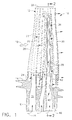
- Illustrated in Figure 1 is an exemplary turbine rotor blade 10, such as the first stage turbine blade in the LPT of a gas turbine engine.
- the blade includes an airfoil 12, platform 14, and dovetail 16 formed in a unitary casting.
- the dovetail 16 mounts the blade radially to the outer perimeter of a supporting rotor disk (not shown), and combustion gases 18 flow around the airfoil 12 during operation to provide energy for powering the rotor disk.
- the airfoil 12 has a generally concave pressure side 20 and a circumferentially opposite, generally convex suction side 22 extending longitudinally or radially from a root 24 at the platform 14 to a radially outer tip 26.
- the two sides extend axially in chord between opposite leading and trailing edges 28,30 and are conventionally configured for extracting energy from the combustion gases during operation.
- the turbine blade is hollow and includes an internal cooling circuit 32 which may have any conventional configuration typically defined by radial partitions bridging the opposite sides of the airfoil and spaced chordally apart forming the exemplary seven radial flow passages therein.
- the flow passages are arranged in suitable circuits such as dedicated impingement cooling circuits for the leading and trailing edges of the airfoil, and a three-pass serpentine cooling circuit in the midchord region of the airfoil.
- Three of the seven flow passages extend through the platform and dovetail to provide three corresponding inlets in the base of the dovetail for receiving pressurized cooling air 34 bled from the compressor (not shown).
- the airfoil includes various film cooling and trailing edge holes around the outer surface thereof which discharge the spent internal cooling air in a conventional manner during operation.
- the damper 36 Disposed in the penultimate, or sixth, flow passage in the blade 10 is an elongate, internal stick damper 36.
- the damper 36 is long and slender and extends in length from the base of the dovetail 16 to just below the airfoil tip 26.
- the damper 36 is configured to conform with the shape of the sixth flow passage in which it is mounted with a slight radial inclination or lean so that centrifugal loads on the damper load the damper in friction against corresponding portions or lands of the airfoil for effecting internal frictional damping during operation.
- Frictional dampers are well known and utilize vibratory motion during operation to frictionally dissipate vibratory excitation energy to dampen the blade airfoil.
- the damper itself must be suitably mounted inside the turbine blade and is subject to substantial centrifugal loads during operation which effect tensile and bending loads in the damper along the radial length thereof, subject to the particular configuration of the damper and blade.
- the damper 36 itself may be otherwise conventional and is modified herein from a single material composition to include different material compositions specifically configured to match the different operating requirements of the damper over its length.
- the damper 36 includes an elongate outer part or rod 38 sized in length to extend inside the airfoil 12 from the platform 14 to a suitable elevation closely adjacent to the airfoil tip.
- the damper also includes a supporting inner part or shank 40 suitably affixed to a proximal end of the outer part 38 and extending therebelow for being retained in the blade below the platform 14.
- the two parts 38,40 of the single damper 36 are specifically formed of different materials for effecting frictional damping inside the airfoil 12 and tensile support below the platform.
- the damper outer part 38 is longitudinally elongate and slender to fit inside the airfoil and includes a proximal end affixed to the distal end of the inner part 40 at a corresponding integral joint 42 therewith.
- the joint 42 is specifically located inside the blade to differentiate the upper part 38 from the supporting damper inner part 40 which is suitably mounted in the blade for carrying the substantial centrifugal loads generated in the damper during operation.
- the damper outer part 38 is formed of a first material having a substantially greater frictional wear resistance capability than the different second material forming the damper inner part 40.
- the second material forming the damper inner part 40 preferably has a substantially greater tensile strength than that of the first material of the damper outer part 38.
- the intervening joint 42 determines the transition location within the damper itself for the different materials and the different performance required therefor.
- the exemplary damper illustrated in Figure 1 is mounted from its radially inner end to the blade dovetail.
- the damper inner part 40 defines a supporting shank extending radially inwardly through the platform and dovetail to reach the base of the dovetail.
- the elongate damper outer part or rod 38 extends radially outwardly from the platform to just short of the airfoil tip as desired for damping effectiveness.
- the centrifugal loads generated in the damper are carried radially inwardly through the outer part and into the inner part before reaching the dovetail itself, which substantially increases the tensile loads in the inner part 40.
- the damper 36 is typically nonlinear and curves or bends to match the three dimensional (3D) configuration of the sixth flow passage in which the damper is mounted.
- the curved configuration of the damper includes an exemplary bend 44 and additionally introduces bending stresses typically in the damper inner part 40 along the bend.
- damper outer part 38 is generally straight radially outwardly above the platform.
- the outer part 38 carries substantially lower loads during operation and laterally engages the supporting lands for frictional contact.
- the damper outer part 38 may be formed of a first material having maximum frictional wear resistance independent of the associated tensile strength thereof.
- the damper inner part 40 may be formed of a different second material having maximum tensile strength independent of wear resistance, with the second material being substantially greater in tensile strength than that of the first material of the outer part 38.
- the material composition of the damper may be preferentially matched to the operating environment and loads which are different on the different portions of the damper.
- the first material forming the damper outer part 38 is selected primarily for its enhanced wear resistance capability and is therefore different than the first material, and may be formed of a cobalt based metal superalloy such as MAR-M-509 (trademark) commercially available from Cannon-Muskegon, Muskegon, MI.
- the second material forming the damper inner part 40 may be formed of a nickel based metal superalloy such as Rene 80 or Rene N5 (trademarks), available from General Electric Company, Fairfield, CT, which have enhanced strength for LCF, HCF, and rupture life at the elevated temperatures experienced by the turbine rotor blade.
- Rene 80 or Rene N5 trademarks
- the first material lacks the tensile strength of the second material, whereas the second material lacks the wear resistance of the first material.
- the strength and useful life of the damper may be maximized while correspondingly maximizing the wear resistance and life thereof for the turbine blade damper application.
- the outer and inner parts 38,40 are coextensive with each other with a substantially constant circular cross section terminating in a suitable mounting block or base 46 at the proximal end of the inner part, which is received in a complementary socket in the base of the dovetail.
- the damper inner part 40 bends laterally from the outer part 38 below the joint 42 to include the exemplary bend 44 located directly adjacent a supporting rib in the plane of the platform.
- the damper inner part 40 extends the full height of the dovetail and platform, with the joint 42 being disposed near the platform just above the bend 44 closer to the mounting block 46 than to the opposite distal end of the longer outer part 38 which extends over the greater length of the airfoil terminating closely adjacent to the airfoil tip.
- the damper outer part 38 may be substantially straight over its full extent inside the airfoil 12, and the damper inner part 40 bends and curves as required to thread through the platform and dovetail to the mounting block 46.
- the joint 42 affixing the two damper parts together is located above the highly loaded inner portion of the damper attached to the base of the airfoil.
- Figure 2 illustrates schematically an exemplary method of making the bimetallic damper 36.
- the outer and inner parts 38,40 are separately formed of their corresponding first and second materials.
- an outer casting 48 of the first material is firstly made in oversize to subsequently form the outer part 38.
- an inner casting 50 is first formed in oversize to subsequently form the inner part 40.
- the two castings 48,50 are suitably machined at corresponding end faces so that the two castings may be joined coextensively end-to-end and suitably bonded together to form the joint 42.
- Possible joining processes include, but not limited to: laser welding; inertia welding; translation friction welding; or brazing to form a strong joint 42 with a minimum heat affected zone.
- the welded castings may then undergo suitable machining to remove therefrom the excess material to form the resulting damper 36.
- suitable machining For example, conventional centerless, high speed precision grinding may be used to spin the joined castings around their longitudinal or axial centerline axis and remove the excess material from the rod portion thereof.
- Conventional electrical discharge machining (EDM) may then be used to remove the excess material from the proximal end of the casting to produce the final mounting block 46.
- the straight machined casting may then be suitably hot formed to bend in particular the damper inner part 40 to the required 3D configuration to match the corresponding profile of the blade passage in which the damper is mounted.
- hot forming the machined casting is heated to its anneal temperature in a suitable molding process for reshaping the damper to the required 3D shape with minimal residual stresses therein.
- any conventional method of manufacture may be used for forming the bimaterial damper, but suitably modified for effecting the different materials required.
- Powder metal forming may also be used for more directly forming the bimetallic damper and minimizing machining or other process steps.
- the damper itself may have any suitable form in which two, or more, different material compositions are used as desired for preferentially matching material performance with the different operating environments inside the specific turbine blade.
- FIG. 3 illustrates another configuration of the damper, designated 52.
- the damper 52 includes a pair of parallel outer parts or rods 38 disposed inside the airfoil and affixed to a common inner part or shank 40 extending through the platform and dovetail.
- the inner part 40 includes a U-shaped bend or fork 54 which is affixed to the pair of outer parts 38 at corresponding joints 42 which separate the second material of the inner part 40 from the different first material common to the two outer parts 38.
- Another form of the mounting block 46 is affixed to the proximal end of the shank 40 and supports the damper to the base of the dovetail.
- the damper 52 includes the common shank or stem 40 and the integral fork 54 both defining the inner part of the damper which in turn supports the two outer rods 38 at the corresponding joints 42.
- the two rods 38 are generally straight and have a small lean to frictionally engage corresponding portions of the airfoil when loaded under centrifugal force.
- the fork 54 of the damper bridges and is trapped at the bottom of a corresponding partition of the airfoil.
- the fork and shank 40 carry the substantial centrifugal loads generated by the damper during operation they are subject to substantial centrifugal stresses for which the high strength second material is best utilized for maximizing damper life.
- the less loaded outer rods 38 are formed of the wear resistant first material for maximizing frictional damping performance thereof with minimal wear.
- Figure 4 illustrates yet another embodiment of the damper, designated 56 again having a pair of the outer parts or rods 38 joined to a common fork 54 at the corresponding joints 42.
- the fork 54 has the generally U-shaped configuration, and is stemless. The fork 54 may therefore be trapped between one of the airfoil partitions thereabove and a suitable pin disposed therebelow.
- the corresponding forks 54 preferably have straight legs joined to the straight outer rods 38 at the corresponding joints 42 which separate the different first and second materials between the outer and inner parts of the dampers.
- the corresponding inner parts of the dampers carry the loads differently and are preferentially formed of the high strength second material described above, and the corresponding outer parts of the dampers are formed of the different wear resistant first material.
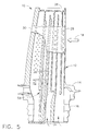
- Figure 5 illustrates yet another embodiment of the damper, designated 58, again having a pair of the outer parts 38 joined to the stemless fork 54.
- the joints 42 are located near the platform 14, and the fork 54 extends over the full height of the platform and dovetail to the base of the dovetail.
- the fork 54 is trapped around one of the blade partitions which extends to the dovetail base, and the centrifugal loads from the fork are carried through that partition into the dovetail during operation.
- the joints 42 are located at the root of the airfoil in relatively low load regions so that the wear resistant first material may be used in the outer rods 38 above the joints 42, and the high strength second material may be used for the damper inner part below the platform and over the full height of the dovetail.
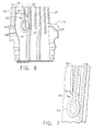
- Figures 6 and 7 illustrate two additional embodiments of the damper, designated 60,62, respectively, in which the fork 64 is bulbous and forms the damper inner part without a stem.
- the bulbous fork 64 is trapped or supported on a corresponding partition of the blade for reducing centrifugal loads in the fork during operation.
- the inner end of the blade partition has a small circular supporting knob disposed within the larger fork 64, whereas in the Figure 7 embodiment, the inner end of the partition has a relatively large knob conforming to the bulbous profile of the fork 64.
- the two joints 42 are located radially outwardly or above the two forks in relatively low load regions of the damper, with the outer rods 38 extending radially outwardly therefrom along opposite sides of the airfoil partition.
- dampers illustrated in Figures 6 and 7 may selectively use the different first and second materials described above for the different outer and inner parts thereof for placing the wear resistant material in the frictional damping portion of the damper, and the high strength material in the load carrying portion of the dampers.
- a significant advantage of the bimetallic damper disclosed above is the introduction of another design configuration addressing the different requirements of strength and wear. Wear resistance and strength in a single material are typically inversely related. A wear resistant material will have a relatively low tensile strength, whereas a high tensile strength material will have a relatively low wear resistance.
- a high strength material may be used in the regions of high load and stress for maximizing life, and a wear resistance material may be used in the areas subject to the high cycle frictional contact, which is typically a low load region.
- the custom tailoring of material composition in the single damper may be used to provide enhanced low cycle fatigue life, high cycle fatigue life, and rupture life while also providing enhanced wear resistance in the portion of the damper experiencing frictional contact with the airfoil.
- the wear resistant outer part of the damper extends radially through the airfoil, it is subject to higher heat loads than the supporting inner part of the damper.
- the outer part will therefore run hotter than the inner part which can be used for additional advantage for certain wear resistant alloys.
- certain wear resistant alloys such as the Cobalt-based example presented above, which create a natural lubricity upon reaching an elevated temperature during operation. This lubricity reduces wear, yet with effective damping performance.
- internal dampers may be configured in various embodiments as disclosed above, they may be suitably modified in length or radial extent to introduce different materials over the outer and inner portions thereof.
- the inner portion of the damper supports the damper inside the turbine blade and is subject to high loading during operation.
- the high strength material may therefore be used in the supporting inner part.
- the damper outer portion is suspended from the inner portion inside the airfoil and may be formed of the different wear resistant material for maximizing life under frictional contact during operation.
Landscapes
- Engineering & Computer Science (AREA)
- Mechanical Engineering (AREA)
- General Engineering & Computer Science (AREA)
- Turbine Rotor Nozzle Sealing (AREA)
Abstract
Description
- The present invention relates generally to gas turbine engines, and, more specifically, to blade damping therein.
- In a gas turbine engine, air is pressurized in a compressor and mixed with fuel in a combustor for generating hot combustion gases. Energy is extracted from the gases in a high pressure turbine (HPT) which powers the compressor. Additional energy is extracted in a low pressure turbine (LPT) for powering a fan in a turbofan aircraft engine application, or for powering an output drive shaft for marine and industrial (M&I) applications.
- Each turbine stage includes a row of turbine rotor blades extending radially outwardly from a supporting rotor disk. During operation, the turbine blades extract energy from the hot combustion gases and are subject to considerable pressure and centrifugal loads, and operate at elevated temperature.
- The blades are typically hollow and include internal cooling circuits through which a portion of pressurized air bled from the compressor is circulated for cooling the individual blades against the heat loads from the combustion gases.
- The turbine blades typically increase in size and length in the successive stages from the combustor for maximizing efficiency of energy extraction as the pressure in the combustion gases decreases in the downstream direction. The turbine blades are subject to vibratory excitation forces due to the aerodynamic and centrifugal loads and behave differently due to the different sizes and configurations of the blades, with different modes of vibration occurring at different resonant frequencies.
- Vibration damping may be effected where desired using under platform vibration dampers, or internal vibration dampers installed inside the individual blades.
- Internal vibration dampers typically extend the length of the turbine blade and are mounted inside the supporting dovetail and are cantilevered freely inside the airfoil.
- Each damper is typically a slender rod having a small lean so that centrifugal forces load the damper radially outwardly against corresponding internal supporting lands inside the airfoil. Frictional vibration between the damper and the airfoil dissipates excitation forces and effectively dampens blade vibration.
- However, frictional damping is subject to wear between the damper and the airfoil, and should be minimized. Yet, the damper itself is subject to substantial centrifugal loads during operation and experiences corresponding tensile and bending stresses along its length.
- Blade life is a paramount design objective, and with the introduction of an internal damper, the life of the damper itself affects the life of the blade. The damper should therefore be formed of a material having sufficiently high strength for effecting long low cycle fatigue (LCF) life, long high cycle fatigue (HCF) life, and long rupture life for the damper. These life factors are typically controlled by the highest steady state stress portions of the damper, which is typically in its supporting portion.
- In contrast, the outer portion of the damper subject to frictional vibration with the airfoil experiences substantially lower stresses during operation, yet is subject to friction wear.
- Standard design practice for introducing blade vibration dampers typically requires a compromise between the wear and strength performance of the damper.
- Accordingly, it is desired to provide a turbine blade damper having improved wear resistance in combination with high strength.
- A turbine blade damper includes an outer part for damping vibration of the blade airfoil and a supporting inner part. The two parts are formed of different materials for the different performance required thereof in the blade.
- The invention, in accordance with preferred and exemplary embodiments, together with further objects and advantages thereof, is more particularly described in the following detailed description taken in conjunction with the accompanying drawings in which:
-
Figure 1 is a partly sectional elevational view of an exemplary gas turbine engine turbine rotor blade having an internal damper therein. -
Figure 2 is a schematic representation for making the damper inFigure 1 in accordance with one embodiment. -
Figure 3 is a partly sectional elevational view of a turbine rotor blade having an internal damper in accordance with another embodiment. -
Figure 4 is an enlarged portion of the airfoil illustrated inFigure 3 having an internal damper in accordance with another embodiment. -
Figure 5 is a partly sectional elevational view of the airfoil illustrated inFigure 3 having a damper in accordance with another embodiment. -
Figure 6 is an enlarged portion of the airfoil illustrated inFigure 3 having the damper in accordance with another embodiment. -
Figure 7 is an enlarged sectional view of a portion of the airfoil illustrated inFigure 6 with a modification of the damper therein. - Illustrated in
Figure 1 is an exemplaryturbine rotor blade 10, such as the first stage turbine blade in the LPT of a gas turbine engine. The blade includes anairfoil 12,platform 14, anddovetail 16 formed in a unitary casting. - The
dovetail 16 mounts the blade radially to the outer perimeter of a supporting rotor disk (not shown), andcombustion gases 18 flow around theairfoil 12 during operation to provide energy for powering the rotor disk. - The
airfoil 12 has a generallyconcave pressure side 20 and a circumferentially opposite, generally convexsuction side 22 extending longitudinally or radially from aroot 24 at theplatform 14 to a radiallyouter tip 26. The two sides extend axially in chord between opposite leading andtrailing edges - The turbine blade is hollow and includes an
internal cooling circuit 32 which may have any conventional configuration typically defined by radial partitions bridging the opposite sides of the airfoil and spaced chordally apart forming the exemplary seven radial flow passages therein. - The flow passages are arranged in suitable circuits such as dedicated impingement cooling circuits for the leading and trailing edges of the airfoil, and a three-pass serpentine cooling circuit in the midchord region of the airfoil.
- Three of the seven flow passages extend through the platform and dovetail to provide three corresponding inlets in the base of the dovetail for receiving pressurized
cooling air 34 bled from the compressor (not shown). The airfoil includes various film cooling and trailing edge holes around the outer surface thereof which discharge the spent internal cooling air in a conventional manner during operation. - Disposed in the penultimate, or sixth, flow passage in the
blade 10 is an elongate,internal stick damper 36. Thedamper 36 is long and slender and extends in length from the base of thedovetail 16 to just below theairfoil tip 26. - The
damper 36 is configured to conform with the shape of the sixth flow passage in which it is mounted with a slight radial inclination or lean so that centrifugal loads on the damper load the damper in friction against corresponding portions or lands of the airfoil for effecting internal frictional damping during operation. - Frictional dampers are well known and utilize vibratory motion during operation to frictionally dissipate vibratory excitation energy to dampen the blade airfoil.
- However, the damper itself must be suitably mounted inside the turbine blade and is subject to substantial centrifugal loads during operation which effect tensile and bending loads in the damper along the radial length thereof, subject to the particular configuration of the damper and blade.
- The
damper 36 itself may be otherwise conventional and is modified herein from a single material composition to include different material compositions specifically configured to match the different operating requirements of the damper over its length. - In a basic configuration, the
damper 36 includes an elongate outer part orrod 38 sized in length to extend inside theairfoil 12 from theplatform 14 to a suitable elevation closely adjacent to the airfoil tip. - The damper also includes a supporting inner part or
shank 40 suitably affixed to a proximal end of theouter part 38 and extending therebelow for being retained in the blade below theplatform 14. - The two
parts single damper 36 are specifically formed of different materials for effecting frictional damping inside theairfoil 12 and tensile support below the platform. - The damper
outer part 38 is longitudinally elongate and slender to fit inside the airfoil and includes a proximal end affixed to the distal end of theinner part 40 at a correspondingintegral joint 42 therewith. Thejoint 42 is specifically located inside the blade to differentiate theupper part 38 from the supporting damperinner part 40 which is suitably mounted in the blade for carrying the substantial centrifugal loads generated in the damper during operation. - Forming the damper with different material compositions improves the ability to match different parts of the damper to the different requirements and functions thereof inside the blade. In particular, the damper
outer part 38 is formed of a first material having a substantially greater frictional wear resistance capability than the different second material forming the damperinner part 40. - Correspondingly, the second material forming the damper
inner part 40 preferably has a substantially greater tensile strength than that of the first material of the damperouter part 38. And, the interveningjoint 42 determines the transition location within the damper itself for the different materials and the different performance required therefor. - The exemplary damper illustrated in
Figure 1 is mounted from its radially inner end to the blade dovetail. The damperinner part 40 defines a supporting shank extending radially inwardly through the platform and dovetail to reach the base of the dovetail. And, the elongate damper outer part orrod 38 extends radially outwardly from the platform to just short of the airfoil tip as desired for damping effectiveness. - The centrifugal loads generated in the damper are carried radially inwardly through the outer part and into the inner part before reaching the dovetail itself, which substantially increases the tensile loads in the
inner part 40. - Furthermore, the
damper 36 is typically nonlinear and curves or bends to match the three dimensional (3D) configuration of the sixth flow passage in which the damper is mounted. The curved configuration of the damper includes anexemplary bend 44 and additionally introduces bending stresses typically in the damperinner part 40 along the bend. - In contrast, the damper
outer part 38 is generally straight radially outwardly above the platform. Theouter part 38 carries substantially lower loads during operation and laterally engages the supporting lands for frictional contact. - Accordingly, the damper
outer part 38 may be formed of a first material having maximum frictional wear resistance independent of the associated tensile strength thereof. - And, the damper
inner part 40 may be formed of a different second material having maximum tensile strength independent of wear resistance, with the second material being substantially greater in tensile strength than that of the first material of theouter part 38. - In this way, the material composition of the damper may be preferentially matched to the operating environment and loads which are different on the different portions of the damper.
- The first material forming the damper
outer part 38 is selected primarily for its enhanced wear resistance capability and is therefore different than the first material, and may be formed of a cobalt based metal superalloy such as MAR-M-509 (trademark) commercially available from Cannon-Muskegon, Muskegon, MI. - The second material forming the damper
inner part 40 may be formed of a nickel based metal superalloy such as Rene 80 or Rene N5 (trademarks), available from General Electric Company, Fairfield, CT, which have enhanced strength for LCF, HCF, and rupture life at the elevated temperatures experienced by the turbine rotor blade. - The first material lacks the tensile strength of the second material, whereas the second material lacks the wear resistance of the first material.
- These two different materials, or bimetals, in the same damper component are used to match the different metals and their properties with the different operating requirements of the damper within the turbine blade.
- Accordingly, the strength and useful life of the damper may be maximized while correspondingly maximizing the wear resistance and life thereof for the turbine blade damper application.
- In the
damper 36 illustrated inFigure 1 , the outer andinner parts base 46 at the proximal end of the inner part, which is received in a complementary socket in the base of the dovetail. - To match the profile of the twisting airfoil blade, the damper
inner part 40 bends laterally from theouter part 38 below the joint 42 to include theexemplary bend 44 located directly adjacent a supporting rib in the plane of the platform. - The damper
inner part 40 extends the full height of the dovetail and platform, with the joint 42 being disposed near the platform just above thebend 44 closer to the mountingblock 46 than to the opposite distal end of the longerouter part 38 which extends over the greater length of the airfoil terminating closely adjacent to the airfoil tip. - In this way, the damper
outer part 38 may be substantially straight over its full extent inside theairfoil 12, and the damperinner part 40 bends and curves as required to thread through the platform and dovetail to the mountingblock 46. And, the joint 42 affixing the two damper parts together is located above the highly loaded inner portion of the damper attached to the base of the airfoil. -
Figure 2 illustrates schematically an exemplary method of making thebimetallic damper 36. The outer andinner parts outer part 38. And, aninner casting 50 is first formed in oversize to subsequently form theinner part 40. - The two
castings - The welded castings may then undergo suitable machining to remove therefrom the excess material to form the resulting
damper 36. For example, conventional centerless, high speed precision grinding may be used to spin the joined castings around their longitudinal or axial centerline axis and remove the excess material from the rod portion thereof. Conventional electrical discharge machining (EDM) may then be used to remove the excess material from the proximal end of the casting to produce thefinal mounting block 46. - The straight machined casting may then be suitably hot formed to bend in particular the damper
inner part 40 to the required 3D configuration to match the corresponding profile of the blade passage in which the damper is mounted. In hot forming, the machined casting is heated to its anneal temperature in a suitable molding process for reshaping the damper to the required 3D shape with minimal residual stresses therein. - Any conventional method of manufacture may be used for forming the bimaterial damper, but suitably modified for effecting the different materials required. Powder metal forming may also be used for more directly forming the bimetallic damper and minimizing machining or other process steps.
- And, the damper itself may have any suitable form in which two, or more, different material compositions are used as desired for preferentially matching material performance with the different operating environments inside the specific turbine blade.
-
Figure 3 illustrates another configuration of the damper, designated 52. In this embodiment, thedamper 52 includes a pair of parallel outer parts orrods 38 disposed inside the airfoil and affixed to a common inner part orshank 40 extending through the platform and dovetail. - The
inner part 40 includes a U-shaped bend or fork 54 which is affixed to the pair ofouter parts 38 at correspondingjoints 42 which separate the second material of theinner part 40 from the different first material common to the twoouter parts 38. Another form of the mountingblock 46 is affixed to the proximal end of theshank 40 and supports the damper to the base of the dovetail. - In the
Figure 3 embodiment, thedamper 52 includes the common shank orstem 40 and theintegral fork 54 both defining the inner part of the damper which in turn supports the twoouter rods 38 at the corresponding joints 42. - The two
rods 38 are generally straight and have a small lean to frictionally engage corresponding portions of the airfoil when loaded under centrifugal force. Thefork 54 of the damper bridges and is trapped at the bottom of a corresponding partition of the airfoil. - Since the fork and
shank 40 carry the substantial centrifugal loads generated by the damper during operation they are subject to substantial centrifugal stresses for which the high strength second material is best utilized for maximizing damper life. Correspondingly, the less loadedouter rods 38 are formed of the wear resistant first material for maximizing frictional damping performance thereof with minimal wear. -
Figure 4 illustrates yet another embodiment of the damper, designated 56 again having a pair of the outer parts orrods 38 joined to acommon fork 54 at the corresponding joints 42. In this embodiment, thefork 54 has the generally U-shaped configuration, and is stemless. Thefork 54 may therefore be trapped between one of the airfoil partitions thereabove and a suitable pin disposed therebelow. - In the similar embodiments illustrated in
Figures 3 and4 , the correspondingforks 54 preferably have straight legs joined to the straightouter rods 38 at the correspondingjoints 42 which separate the different first and second materials between the outer and inner parts of the dampers. - Although the load paths are different through the different dampers illustrated in
Figures 1 ,3 , and4 the corresponding inner parts of the dampers carry the loads differently and are preferentially formed of the high strength second material described above, and the corresponding outer parts of the dampers are formed of the different wear resistant first material. -
Figure 5 illustrates yet another embodiment of the damper, designated 58, again having a pair of theouter parts 38 joined to thestemless fork 54. In this embodiment, thejoints 42 are located near theplatform 14, and thefork 54 extends over the full height of the platform and dovetail to the base of the dovetail. - The
fork 54 is trapped around one of the blade partitions which extends to the dovetail base, and the centrifugal loads from the fork are carried through that partition into the dovetail during operation. - The
joints 42 are located at the root of the airfoil in relatively low load regions so that the wear resistant first material may be used in theouter rods 38 above thejoints 42, and the high strength second material may be used for the damper inner part below the platform and over the full height of the dovetail. -
Figures 6 and 7 illustrate two additional embodiments of the damper, designated 60,62, respectively, in which thefork 64 is bulbous and forms the damper inner part without a stem. - The
bulbous fork 64 is trapped or supported on a corresponding partition of the blade for reducing centrifugal loads in the fork during operation. InFigure 6 , the inner end of the blade partition has a small circular supporting knob disposed within thelarger fork 64, whereas in theFigure 7 embodiment, the inner end of the partition has a relatively large knob conforming to the bulbous profile of thefork 64. - In both embodiments illustrated in
Figures 6 and 7 , the twojoints 42 are located radially outwardly or above the two forks in relatively low load regions of the damper, with theouter rods 38 extending radially outwardly therefrom along opposite sides of the airfoil partition. - Yet again, the dampers illustrated in
Figures 6 and 7 may selectively use the different first and second materials described above for the different outer and inner parts thereof for placing the wear resistant material in the frictional damping portion of the damper, and the high strength material in the load carrying portion of the dampers. - A significant advantage of the bimetallic damper disclosed above is the introduction of another design configuration addressing the different requirements of strength and wear. Wear resistance and strength in a single material are typically inversely related. A wear resistant material will have a relatively low tensile strength, whereas a high tensile strength material will have a relatively low wear resistance.
- By preferentially introducing different materials in the different regions of the internal damper, a high strength material may be used in the regions of high load and stress for maximizing life, and a wear resistance material may be used in the areas subject to the high cycle frictional contact, which is typically a low load region.
- The custom tailoring of material composition in the single damper may be used to provide enhanced low cycle fatigue life, high cycle fatigue life, and rupture life while also providing enhanced wear resistance in the portion of the damper experiencing frictional contact with the airfoil.
- Since the wear resistant outer part of the damper extends radially through the airfoil, it is subject to higher heat loads than the supporting inner part of the damper. The outer part will therefore run hotter than the inner part which can be used for additional advantage for certain wear resistant alloys. such as the Cobalt-based example presented above, which create a natural lubricity upon reaching an elevated temperature during operation. This lubricity reduces wear, yet with effective damping performance.
- Since internal dampers may be configured in various embodiments as disclosed above, they may be suitably modified in length or radial extent to introduce different materials over the outer and inner portions thereof. The inner portion of the damper supports the damper inside the turbine blade and is subject to high loading during operation. The high strength material may therefore be used in the supporting inner part.
- In contrast, the damper outer portion is suspended from the inner portion inside the airfoil and may be formed of the different wear resistant material for maximizing life under frictional contact during operation.
- While there have been described herein what are considered to be preferred and exemplary embodiments of the present invention, other modifications of the invention shall be apparent to those skilled in the art from the teachings herein, and it is, therefore, desired to be secured in the appended claims all such modifications as fall within the true spirit and scope of the invention.
- Accordingly, what is desired to be secured by Letters Patent is the invention as defined and differentiated in the following claims in which we claim:
Claims (10)
- A damper (36) for a turbine blade (10) including a hollow airfoil (12) joined at a platform (14) to a supporting dovetail (16), said damper comprising:an outer part (38) sized to extend inside said airfoil (12) from said platform (14);an inner part (40) affixed to a proximal end of said outer part (38) and extending therebelow for being retained in said blade below said platform (14); andsaid parts (38,40) being formed of different materials for effecting frictional damping inside said airfoil (12) and tensile support below said platform (14).
- A damper according to claim 1, wherein said outer part (38) comprises a first material having a greater frictional wear resistance than a different second material in said inner part (40).
- A damper according to claim 1 or claim 2, wherein said second material in said inner part (40) has a greater tensile strength than said first material in said outer part (38).
- A damper according to any one of the preceding claims, wherein said outer part (38) is generally straight, and said inner part (40) includes a bend (44).
- A damper according to any one of the preceding claims, wherein said outer and inner parts (38,40) are coextensive and terminate at a mounting block (46) at the proximal end of said inner part (40).
- A damper according to any one of the preceding claims, wherein said inner part (40) bends laterally from said outer part (38) below a joint (42) therewith.
- A damper according to any one of the preceding claims, wherein said joint (42) is disposed closer to said block (46) than to the distal end of the said outer part (38).
- A damper according to any one of the preceding claims, further comprising a pair of said outer parts (38) affixed at corresponding joints (42) to a common fork (54) in said inner part (40).
- A damper according to any one of the preceding claims, wherein said inner part (40) further includes a stem integrally joined to said fork (54).
- A damper according to claim 8 wherein said fork (54) is stemless.
Applications Claiming Priority (1)
| Application Number | Priority Date | Filing Date | Title |
|---|---|---|---|
| US11/767,548 US7824158B2 (en) | 2007-06-25 | 2007-06-25 | Bimaterial turbine blade damper |
Publications (2)
| Publication Number | Publication Date |
|---|---|
| EP2009240A2 true EP2009240A2 (en) | 2008-12-31 |
| EP2009240A3 EP2009240A3 (en) | 2012-12-12 |
Family
ID=39590392
Family Applications (1)
| Application Number | Title | Priority Date | Filing Date |
|---|---|---|---|
| EP08154669A Withdrawn EP2009240A3 (en) | 2007-06-25 | 2008-04-17 | Bimaterial turbine blade damper |
Country Status (4)
| Country | Link |
|---|---|
| US (1) | US7824158B2 (en) |
| EP (1) | EP2009240A3 (en) |
| JP (1) | JP5203027B2 (en) |
| CA (1) | CA2629226C (en) |
Cited By (2)
| Publication number | Priority date | Publication date | Assignee | Title |
|---|---|---|---|---|
| EP2071128A3 (en) * | 2007-12-13 | 2012-06-20 | General Electric Company | Monolithic or bi-metallic damper for a turbine blade |
| EP2989296A4 (en) * | 2013-04-23 | 2016-12-07 | United Technologies Corp | Internally damped airfoiled component and method |
Families Citing this family (20)
| Publication number | Priority date | Publication date | Assignee | Title |
|---|---|---|---|---|
| US8915718B2 (en) * | 2012-04-24 | 2014-12-23 | United Technologies Corporation | Airfoil including damper member |
| US9249668B2 (en) | 2012-04-24 | 2016-02-02 | United Technologies Corporation | Airfoil with break-way, free-floating damper member |
| US9267380B2 (en) * | 2012-04-24 | 2016-02-23 | United Technologies Corporation | Airfoil including loose damper |
| US9121288B2 (en) * | 2012-05-04 | 2015-09-01 | Siemens Energy, Inc. | Turbine blade with tuned damping structure |
| EP2986822B8 (en) * | 2013-04-16 | 2021-04-07 | Raytheon Technologies Corporation | Rotors with elastic modulus mistuned airfoils |
| US10914320B2 (en) * | 2014-01-24 | 2021-02-09 | Raytheon Technologies Corporation | Additive manufacturing process grown integrated torsional damper mechanism in gas turbine engine blade |
| US10260355B2 (en) | 2016-03-07 | 2019-04-16 | Honeywell International Inc. | Diverging-converging cooling passage for a turbine blade |
| US10724376B2 (en) | 2018-02-08 | 2020-07-28 | General Electric Company | Airfoil having integral fins |
| JP6991912B2 (en) | 2018-03-28 | 2022-01-13 | 三菱重工業株式会社 | Rotating machine |
| CN110469368A (en) * | 2019-08-02 | 2019-11-19 | 中国航发贵阳发动机设计研究所 | A kind of turbine rotor blade |
| US11371358B2 (en) | 2020-02-19 | 2022-06-28 | General Electric Company | Turbine damper |
| US11739645B2 (en) | 2020-09-30 | 2023-08-29 | General Electric Company | Vibrational dampening elements |
| US11536144B2 (en) | 2020-09-30 | 2022-12-27 | General Electric Company | Rotor blade damping structures |
| US11572791B1 (en) | 2022-01-12 | 2023-02-07 | General Electric Company | Vibration damping system for turbine nozzle or blade using damper pins with wire mesh members 1HEREON |
| US11634991B1 (en) | 2022-01-12 | 2023-04-25 | General Electric Company | Vibration damping system for turbine nozzle or blade using elongated body and wire mesh member |
| US11519276B1 (en) | 2022-01-12 | 2022-12-06 | General Electric Company | Vibration damping system for turbine blade or nozzle, retention system therefor, and method of assembly |
| US11976565B2 (en) | 2022-07-27 | 2024-05-07 | Ge Infrastructure Technology Llc | Nested damper pin and vibration dampening system for turbine nozzle or blade |
| US12071862B2 (en) | 2022-07-27 | 2024-08-27 | Ge Infrastructure Technology Llc | Vibration damping system for turbine nozzle or blade using stacked plate members |
| FR3147836B1 (en) * | 2023-04-11 | 2025-10-03 | Safran Aircraft Engines | BLADE SECTOR FOR MOBILE WHEEL OF AN AIRCRAFT TURBOMACHINE MODULE, INCLUDING AN IMPROVED DYNAMIC DAMPING DEVICE |
| US12371998B2 (en) | 2023-06-29 | 2025-07-29 | Ge Infrastructure Technology Llc | Nested damper pin and vibration dampening system for turbine nozzle or blade |
Family Cites Families (28)
| Publication number | Priority date | Publication date | Assignee | Title |
|---|---|---|---|---|
| US2460351A (en) * | 1945-11-30 | 1949-02-01 | Rheem Mfg Co | Rotor blade |
| US2566701A (en) * | 1946-10-23 | 1951-09-04 | Curtiss Wright Corp | Reinforcement for filled hollow steel blades |
| FR981599A (en) * | 1948-12-31 | 1951-05-28 | Vibration damping device | |
| US2689107A (en) * | 1949-08-13 | 1954-09-14 | United Aircraft Corp | Vibration damper for blades and vanes |
| US3027138A (en) * | 1951-12-10 | 1962-03-27 | Power Jets Res & Dev Ltd | Turbine blades |
| US2809802A (en) * | 1952-09-10 | 1957-10-15 | Gen Electric | Damping turbine blades |
| US2828941A (en) * | 1952-12-24 | 1958-04-01 | United Aircraft Corp | Blade damping means |
| US2920868A (en) * | 1955-10-05 | 1960-01-12 | Westinghouse Electric Corp | Dampened blade structure |
| US2984453A (en) * | 1957-03-25 | 1961-05-16 | Westinghouse Electric Corp | Vibration damper for blading in elastic fluid apparatus |
| US3973874A (en) * | 1974-09-25 | 1976-08-10 | General Electric Company | Impingement baffle collars |
| US4188171A (en) * | 1977-08-02 | 1980-02-12 | The Boeing Company | Rotor blade internal damper |
| FR2474095B1 (en) * | 1980-01-17 | 1986-02-28 | Rolls Royce | VIBRATION DAMPING DEVICE FOR MOBILE BLADES OF A GAS TURBINE ENGINE |
| GB2093126B (en) * | 1981-02-12 | 1984-05-16 | Rolls Royce | Rotor blade for a gas turbine engine |
| GB2097479B (en) * | 1981-04-24 | 1984-09-05 | Rolls Royce | Cooled vane for a gas turbine engine |
| US4526512A (en) * | 1983-03-28 | 1985-07-02 | General Electric Co. | Cooling flow control device for turbine blades |
| US5165860A (en) * | 1991-05-20 | 1992-11-24 | United Technologies Corporation | Damped airfoil blade |
| JPH0792002B2 (en) * | 1991-12-26 | 1995-10-09 | ゼネラル・エレクトリック・カンパニイ | Damper assembly for gas turbine engine strut |
| US5232344A (en) * | 1992-01-17 | 1993-08-03 | United Technologies Corporation | Internally damped blades |
| US5407321A (en) * | 1993-11-29 | 1995-04-18 | United Technologies Corporation | Damping means for hollow stator vane airfoils |
| US5820343A (en) * | 1995-07-31 | 1998-10-13 | United Technologies Corporation | Airfoil vibration damping device |
| GB9906450D0 (en) * | 1999-03-19 | 1999-05-12 | Rolls Royce Plc | Aerofoil blade damper |
| US6155789A (en) * | 1999-04-06 | 2000-12-05 | General Electric Company | Gas turbine engine airfoil damper and method for production |
| US6685435B2 (en) * | 2002-04-26 | 2004-02-03 | The Boeing Company | Turbine blade assembly with stranded wire cable dampers |
| DE10356237A1 (en) * | 2003-12-02 | 2005-06-30 | Alstom Technology Ltd | Damping arrangement for a blade of an axial turbine |
| US6929451B2 (en) * | 2003-12-19 | 2005-08-16 | United Technologies Corporation | Cooled rotor blade with vibration damping device |
| US7121801B2 (en) * | 2004-02-13 | 2006-10-17 | United Technologies Corporation | Cooled rotor blade with vibration damping device |
| US7413405B2 (en) * | 2005-06-14 | 2008-08-19 | General Electric Company | Bipedal damper turbine blade |
| US7270517B2 (en) * | 2005-10-06 | 2007-09-18 | Siemens Power Generation, Inc. | Turbine blade with vibration damper |
-
2007
- 2007-06-25 US US11/767,548 patent/US7824158B2/en not_active Expired - Fee Related
-
2008
- 2008-04-17 CA CA2629226A patent/CA2629226C/en not_active Expired - Fee Related
- 2008-04-17 EP EP08154669A patent/EP2009240A3/en not_active Withdrawn
- 2008-04-24 JP JP2008113336A patent/JP5203027B2/en not_active Expired - Fee Related
Non-Patent Citations (1)
| Title |
|---|
| None * |
Cited By (5)
| Publication number | Priority date | Publication date | Assignee | Title |
|---|---|---|---|---|
| EP2071128A3 (en) * | 2007-12-13 | 2012-06-20 | General Electric Company | Monolithic or bi-metallic damper for a turbine blade |
| US8267662B2 (en) | 2007-12-13 | 2012-09-18 | General Electric Company | Monolithic and bi-metallic turbine blade dampers and method of manufacture |
| EP2989296A4 (en) * | 2013-04-23 | 2016-12-07 | United Technologies Corp | Internally damped airfoiled component and method |
| US10697303B2 (en) | 2013-04-23 | 2020-06-30 | United Technologies Corporation | Internally damped airfoiled component and method |
| US11668197B2 (en) | 2013-04-23 | 2023-06-06 | Raytheon Technologies Corporation | Internally damped airfoiled component |
Also Published As
| Publication number | Publication date |
|---|---|
| CA2629226C (en) | 2014-06-10 |
| US7824158B2 (en) | 2010-11-02 |
| EP2009240A3 (en) | 2012-12-12 |
| CA2629226A1 (en) | 2008-12-25 |
| JP5203027B2 (en) | 2013-06-05 |
| US20080313899A1 (en) | 2008-12-25 |
| JP2009002327A (en) | 2009-01-08 |
Similar Documents
| Publication | Publication Date | Title |
|---|---|---|
| CA2629226C (en) | Bimaterial turbine blade damper | |
| EP1617044B1 (en) | Selectively thinned turbine blade | |
| JP5419433B2 (en) | Monolithic and bimetallic turbine blade damper and method of manufacturing the same | |
| US5738491A (en) | Conduction blade tip | |
| CN103084780B (en) | Method for repairing turbine bucket tip | |
| EP1657405B1 (en) | Stator vane assembly for a gas turbine | |
| US7984547B2 (en) | Method for manufacturing and/or repairing components for gas turbines | |
| US7736124B2 (en) | Damper configured turbine blade | |
| US4682935A (en) | Bowed turbine blade | |
| US6250166B1 (en) | Simulated dovetail testing | |
| JP6124787B2 (en) | Lightweight shroud for rotor blades | |
| JP2004523687A (en) | Turbine blades with pre-segmented squealer tips | |
| US5913661A (en) | Striated hybrid blade | |
| CN106337696A (en) | System and method for turbine blade repair | |
| JP2021092222A (en) | Damper stack for turbomachine rotor blade | |
| EP2444192A2 (en) | Support collar geometry for linear friction welding | |
| JP2016000994A (en) | Turbine bucket assembly and turbine system | |
| JP2005201242A (en) | How to repair a gas turbine rotor blade | |
| EP1734228A2 (en) | Turbine bucket tip cap | |
| US9394795B1 (en) | Multiple piece turbine rotor blade | |
| CN108060946A (en) | For repairing the screw thread test specimen of superalloy component | |
| EP3927943B1 (en) | Tip repair of a turbine component using a composite tip boron base pre-sintered preform | |
| WO2017146724A1 (en) | Damping for fabricated hollow turbine blades |
Legal Events
| Date | Code | Title | Description |
|---|---|---|---|
| PUAI | Public reference made under article 153(3) epc to a published international application that has entered the european phase |
Free format text: ORIGINAL CODE: 0009012 |
|
| AK | Designated contracting states |
Kind code of ref document: A2 Designated state(s): AT BE BG CH CY CZ DE DK EE ES FI FR GB GR HR HU IE IS IT LI LT LU LV MC MT NL NO PL PT RO SE SI SK TR |
|
| AX | Request for extension of the european patent |
Extension state: AL BA MK RS |
|
| PUAL | Search report despatched |
Free format text: ORIGINAL CODE: 0009013 |
|
| AK | Designated contracting states |
Kind code of ref document: A3 Designated state(s): AT BE BG CH CY CZ DE DK EE ES FI FR GB GR HR HU IE IS IT LI LT LU LV MC MT NL NO PL PT RO SE SI SK TR |
|
| AX | Request for extension of the european patent |
Extension state: AL BA MK RS |
|
| RIC1 | Information provided on ipc code assigned before grant |
Ipc: F01D 5/16 20060101AFI20121108BHEP Ipc: F01D 5/28 20060101ALI20121108BHEP |
|
| 17P | Request for examination filed |
Effective date: 20130612 |
|
| RBV | Designated contracting states (corrected) |
Designated state(s): AT BE BG CH CY CZ DE DK EE ES FI FR GB GR HR HU IE IS IT LI LT LU LV MC MT NL NO PL PT RO SE SI SK TR |
|
| AKX | Designation fees paid |
Designated state(s): DE FR GB IT SE |
|
| GRAP | Despatch of communication of intention to grant a patent |
Free format text: ORIGINAL CODE: EPIDOSNIGR1 |
|
| INTG | Intention to grant announced |
Effective date: 20170921 |
|
| STAA | Information on the status of an ep patent application or granted ep patent |
Free format text: STATUS: THE APPLICATION IS DEEMED TO BE WITHDRAWN |
|
| 18D | Application deemed to be withdrawn |
Effective date: 20180202 |