BACKGROUND
-
Nitridosilicates, oxonitridosilicates, or oxonitridoalumino-silicates, which are derived from oxosilicates by formal exchanges of oxygen by nitrogen and/or silicon by aluminum, are of great interest owing to their outstanding thermal, chemical, and mechanical stability and structural diversity. Recently, these compounds have been extensively studied as host lattices for phosphors, which exhibit unusual, interesting luminescence properties when activated by rare earth ions, such as M2Si5N8: Eu2+, Ce3+, MSi2O2-dN2+2/3d: Eu2+, Ce3+ 3+ (M=Ca, Sr, Ba), CaSiN2:Eu2+, Ce3+, MgSiN2: Eu2+, MYSi4N7 (M = Sr, Ba) : Eu2+, Ce 3+, MSixAl2-xO4-xNx: EU2+ (M=Ca, Sr, Ba), a -SiAlON: RE (RE = Eu2+, Ce3+, Yb2+, Tb3+, Pr3+, Sm3+) . β-SiAlON: Eu2+, and CaAlSiN3:Eu2+. Most importantly, these phosphors emit visible light efficiently under near-ultraviolet or blue light irradiation and have superior thermal and chemical stability to their oxide and sulfide counterparts, allowing them to be used as down-conversion luminescent materials for white light-emitting diodes (LEDs). A series of compounds MSiN2 (M = Be, Mg, Ca, Sr, Ba) have been reported for many years but for which only the ordered wurtzite structures of BeSiN2 and MgSiN2 with three-dimensional frameworks of vertex-sharing SiN4 tetrahedra are known. However, recently, the structure of MSiN2 (M=Ca, Sr, Ba) has been solved for the single crystal, which has been grown form molten sodium at 900-1100 °C. BaSiN2 crystallizes in space group Cmca. The structure consists of pairs of SiN4 tetrahedra edge-linked to form bowtie-shaped Si2N6 dimers which share vertexes to form layers and has no analogue in oxide chemistry. SrSiN2 has a distorted form of this structure and crystallizes in space group P21/c. In MSiN2 (M=Sr, Ba), there is only one crystallographic M site. CaSiN2 crystallizes in space group Pbca. The structure of CaSiN2 contains only vertexsharing SiN4 tetrahedra, linked to form a three-dimensional stuffed-cristobalite type framework isostructural with KGaO2. No investigations have been focused on studying the photoluminescence properties of rare earth in the hosts of MSiN2 (M=Sr, Ba)
SUMMARY OF INVENTION
-
This invention discloses alkaline earth silicon nitride phosphors that are activated by Ce3+ and/or Eu 2+.
-
In a preferred embodiment of the invention, the phosphor shows one of the following formulas: SrSiN2: Eu2+, BaSiN2 : Eu2+, SrSiN2:Ce3+, BaSiN2:Ce3+.
-
In an embodiment of the invention, SrSiN2 and BaSiN2 are mixed to Sr(1-x)Ba(x)SiN2 that provides a host lattice, wherein 0 =x = 1.
-
In a further embodiment of the invention, Sr-ions and/or Ba-ions are replaced partially or completely by divalent metal ions M like Mg, Ca, Zn, Be resulting in the following formula of the host lattice:
-
In a further embodiment of the invention, Si is replaced partially or completely by Ge resulting in the following formula of the host lattice:
-
In a further embodiment of the invention, [(Sr, Ba)Si]
6+ is replaced partially or completely by (LaAl)
6+ resulting in the following formula of the host lattice:
-
La can be replaced partially or completely by Sc, Y, and/or a lanthanide. Al can be replaced partially or completely by B, Ga, and/or Sc.
-
In a further embodiment of the invention, [(Sr, Ba)Si]
6+ is replaced partially or completely by (NaP)
6+ resulting in the following formula of the host lattice:
-
Na can be replaced partially or completely by Li, K, Rb, and/or Cs.
-
In a further embodiment of the invention, [(Sr, Ba)N]
- is replaced partially or completely by (NaO)
- resulting in the following formula of the host lattice:
-
Na can be replaced partially or completely by Li, K, Rb, and/or Cs.
-
In a further embodiment of the invention, (SiN)
+ is replaced partially or completely by (AlO)
+ resulting in the following formula of the host lattice:
-
Al can be replaced partially or completely by B, Ga, and/or Sc.
-
In all cases, the respective host lattices of the phosphor compositions are activated by Ce3+ and/or Eu2+ ions. The activator concentration covers the range from more largely zero up to 0.5 atomic portions, or in another embodiment of the invention, from more largely zero up to 50 atomic per cent. In a further embodiment of the invention, the concentration of the activator ions is more than 50 atomic percent.
-
In a further embodiment of the invention, other rare earth ions like Ce, Yb, Tb, Gd, Dy, Sm or others are included in the phosphor in order to act as co-activator and/or sensitizer.
-
In a further embodiment of the invention, transition metal ions like Mn, V, Nb, or others and/or main group elements like, Bi, Sb, or others are included in the phosphor in order to act as co-activator and/or sensitizer. The concentrations of the co-activators and/or sensitizers are likewise accurately specified. In an embodiment of the invention, these concentrations are adjusted in a range from larger/directly zero up to 50 atomic per cent.
-
In a general embodiment of the invention, the Si/M ratio in the phosphor is 1 (M= Sr, Ba). In particular embodiments of the invention, the Si/M ratio is extended to higher Si/M values, e.g., Si/M = 2.5 (i.e. M2Si5N8) and Si/M = 7 (i.e. MSi7N10). These compounds can be mixed with MSiN2.
-
In a further embodiment of the invention, the phosphor is protected against harmful environmental conditions like moisture, reactive gases, reactive chemicals etc. by surface coating or particle encapsulation with relevant organic or inorganic compounds. For the coating for example fluorides, phosphates, oxides or nitrides of the elements Al, Si, Ti, Y, La, Gd or Lu can be used, if they protect the phosphor particles reliably and if they exhibit optical windows for the excitation and for the emission radiation at the same time.
-
The coating or encapsulation can be realized for example with the help of chemical vapour deposition (CVD) or plasma enhanced CVD (PECVD).
-
The applied coating materials and methods are not limited to the indicated examples.
-
The inventive phosphor may be synthesised by methods using Sr-nitride, Eu-nitride and Si3N4. Furthermore, the inventive phosphor may be synthesised by methods starting with Si3N4, Eu-nitride and Sr metal, which is in situ nitrided. Also, mixtures of Si/Eu/Sr may be nitrided. Further, mixtures of C or C-containing substances like SiC as well as SiO2, Eu2O3 and/or SrO may be carbothermally reduced and nitrided. An ammonolysis of /SiO2/Eu2O3/SrO mixtures may be performed in NH3 gas atmosphere. Furthermore, CVD reactions between Sr/Eu/Si-precursors and NH3 may be performed. Fluxes may be used in order to control particle shape and particle size distribution.
-
Eu and Ce-doped MSiN2 (M=Ba, Sr) phosphors can be prepared by the following way. The binary nitride precursors SrNx(x~0-0.66), BaNx(x~0-0.66) and EuNx (x~0-1.0) were pre-prepared by the reaction of the pure strontium metal (Aldrich, 99.9 %, pieces), barium metal (Aldrich, 99.9 %, pieces) and Eu metal (Csre, 99.9 %, lumps) under flowing dried nitrogen at 800, 550, and 800 °C, respectively, for 12 h in a horizontal tube furnace. In addition, a-Si3N4 powder (Permascand, P95H, a content 93.2 %; Oxygen content: ~1.5), Ce (Alfa, >99 %, lumps) and Li (Merck, >99 %, lumps) are used as the as-received raw materials.
-
Polycrystalline M1-xEuxSiN2 (0 = x = 0.1) and M1-2xCexLixSiN2 (0 = x = 0.02) powders were prepared by a solid state reaction method at high temperature. The appropriate amounts of metal (Ce, Li), SrNx, BaNx and EuNx as well as a-Si3N4 powders were weighed out and subsequently mixed and ground together in an agate mortar. The powder mixtures were then transferred into molybdenum crucibles. All processes were carried out in a purified-nitrogen-filled glove-box. Subsequently those powder mixtures were fired in a horizontal tube furnace at 1250 °C for 16 h under flowing 90 % N2-10 % H2 atmosphere. After firing, the samples were gradually cooled down to the room temperature in the furnace. There was no apparent reaction of the prepared nitrides with the Mo crucibles.
-
Quantities for raw materials of BaSiN
2:Eu
2+ are for example:
-
Quantities for raw materials of SrSiN
2:Eu
2+ are for example:
-
In an embodiment of the invention, the phosphor shows excitation bands in the range of 200-480 nm.
-
On the other side, it could be shown that the phosphors of the invention exhibit an intensive luminescence when they are excited with cathode (CR) or X-ray radiation. Since nitrides in general have a lower band gap energy (related to other host lattices), a higher energy conversion efficiency is expected.
-
Due to the described luminescence characteristics the phosphor according to the present invention can be used as a radiation converter for the transformation of cathode or X-rays, UV, violet or blue radiation into a longer-wave visible light that is emitted by the phosphor preferably in green to red spectral region.
-
The inventive phosphor can be used in technical devices like cathode ray tubes (CRT), X-ray intensifying screens or other X-ray image converters, special laser based large screen displays, fluorescent lamps, coloured light or white emitting LED's, and photovoltaic cells or greenhouse foils or glasses and many more.
-
The inventive phosphor can be exited by excitation sources like electron or X-ray generators, high or low-pressure discharge plasmas, UV or blue emitting organic or inorganic light emitting diodes (LED) or appropriate lasers or laser diodes, or in addition, inorganic thin or thick electroluminescent screens.
-
The application of the inventive phosphors is not limited to the indicated examples.
-
The inventive phosphor can be used as single component in a relevant light emitting element or in combination with other red yellow, green, and/or blue-emitting phosphors in order to improve the performance of the respective application. The latter meets for example the improvement of the colour rendering indices (CRI) of fluorescent lamps and white emitting LED's.
-
All measurements were performed on finely ground samples, which were analyzed by X-ray powder diffraction (Rigaku, D/MAX-B) using Cu-Ka radiation at 40 kV and 30 mA with a graphite monochromator. The phase formation is checked by the normal scan (0.6°/min) in the range of 10-90° 2?. All the XRD measurements were performed at room temperature in the air. All the samples are shown to be pure phases and the powder X-ray diffraction patterns of undoped or doped SrSiN2 and BaSiN2 samples are in good agreement with the reported powders patterns in JCPDS 22-1438 and 36-1257, respectively.
-
The diffuse reflectance, emission and excitation spectra of the samples were measured at room temperature by a Perkin Elmer LS 50B spectrophotometer equipped with a Xe flash lamp. The reflection spectra were calibrated with the reflection of black felt (reflection 3%) and white barium sulfate (BaSO4, reflection ~100 %) in the wavelength region of 230-700 nm. The excitation and emission slits were set at 15 nm. The emission spectra were corrected by dividing the measured emission intensity by the ratio of the observed spectrum of a calibrated W-lamp and its known spectrum from 300 to 900 nm. Excitation spectra were automatically corrected for the variation in the lamp intensity by a second photomultiplier and a beam-splitter. All the spectra were measured with a scan speed of 400 nm/min. All of the luminescence spectra were recorded at room temperature in air.
BRIEF DESCRIPTION OF THE DRAWINGS
-
The foregoing and other features and advantages of the present invention will become more readily appreciated as the same become better understood by reference to the following detailed description of the preferred embodiment of the invention when taken in conjunction with the accompanying drawings, wherein:
- Fig. 1
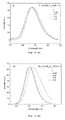
- Diffuse reflection spectra of M1-xEuxSiN2:
- Fig. 2
- Diffuse reflection spectra of M0.96Ce0.02Li0.02SiN2 (M= Sr, Ba).
- Fig. 3
- Emission spectra of M1-xEuxSiN2 under excitation wavelength of 400 nm: (a) M=Sr, (b) M =Ba.
- Fig. 4
- Excitation spectra of M1-xEuxSiN2 :
- Fig. 5
- the emission intensities of M1-xEuxSiN2 under excitation wavelength of 400 nm and the changes in Stokes shift as a function of the Eu concentration: (a) M=Sr, (b) M =Ba.
- Fig. 6
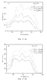
- Typical excitation and emission spectra of SrSiN2: Ce, Li; and
- Fig. 7
- Typical excitation and emission spectra of BaSiN2: Ce, Li.
DETAILED DESCRIPTION
-
Fig. 1 shows the diffuse reflection spectra of undoped and Eu2+-doped MSiN2 (M = Sr, Ba) samples. Fig 1 (a) shows the diffuse reflection spectrum of undoped and Eu2+-doped SrSiN2 samples. Fig 1 (b) shows the diffuse reflection spectrum of undoped and Eu2+-doped BaSiN2 samples. Both undoped and Eu2+-doped samples show a remarkable drop in reflection in the UV range around 300 nm with an estimated band gap at about 258 nm (~4.8 eV) for M = Sr, 266 nm (4.7 eV) for M = Ba, corresponding to the valence-to-conduction band transitions of the MSiN2 host lattice. The intense reflection in the visible spectral range is in agreement with the observed grey-white daylight color for undoped MSiN2. Obviously, two broad absorption bands can be seen from the reflection spectra of low Eu concentration samples. One is the main absorption in the wavelength range of 350-490 nm, another is a short-wavelength absorption band in the wavelength rang of 300-360 nm. The two broad absorption bands both can be attributed to the absorption of the Eu2+ ions due to the absence of them in undoped MSiN2 samples. Moreover, the intensities of them increase for higher Eu concentration. In contrast to the undoped samples, the daylight color of M1-xEuxSiN2 shows light orange to orange for M = Sr and yellow to orange for M = Ba varying with the Eu concentration (0 < x = 0.1) as a result of a strong absorption in the visible range around 350 - 490 nm. Additionally, the onset of the reflection drop significantly shifts to a longer-wavelength as the Eu concentration increases indicating that the absorption range can be tailored by the Eu content.
-
Fig. 2 shows the typical diffuse reflection spectra of Ce3+ and Li+-codoped MSiN2 (M=Sr, Ba). The diffuse reflection spectra of undoped samples were also plotted as a comparison. The intense reflection in the visible spectral range is in agreement with the observed grey-white daylight color for Ce3+-doped MSiN2. It is interesting to note that the Ce3+ ion shows absorption in the UV-blue range (around 400 nm) in both SrSiN2 and BaSiN2 hosts.
-
Fig. 3 (a) and (b) show the typical emission spectra of Sr1-xEuxSiN2 and Ba1-xEuxSiN2 (0 < x = 0.1), respectively. Eu is present as the divalent ion in both Eu-doped BaSiN2 and SrSiN2 samples due to the absence of sharp f-f transition lines characteristic for Eu3+ in their emission spectra. As a result, all the broad emissions in the sample of M1-xEuxSiN2 (0 < x = 0.1) : Eu2+ (M=Sr, Ba) are essentially assigned to the 4f65d1 ? 4f7 transition of the Eu2+ ion. Sr1-xEuxSiN2 (0 < x = 0.1) shows a broad emission band in the wavelength range of 550-850 nm with maxima from 670 to 685 nm with increasing the Eu concentration, while the sample of Ba1-xEuxSiN2 (0 < x = 0.1) shows a broad emission band in the wavelength range of 500-750 nm with maxima from 602 to 628 nm with the increasing the Eu concentration. The reasons for the red shift will be discussed in detail below.
-
Typical excitation spectra of MSiN2: Eu2+ (M= Sr, Ba) are presented in Fig. 4. In Fig. 4 (a), typical excitation spectra of SrSiN2: Eu2+ are shown. In Fig. 4 (b), typical excitation spectra of BaSiN2: Eu2+ are shown. Roughly speaking, there are four dominated broad bands in the excitation spectra of MSiN2: Eu2+ (M= Sr, Ba). The position of these excitation bands is almost independent of the type of the M ions, the Eu concentration and the crystal structure, peaking at about 303, 340, 395 and 466 nm. Several weak excitation bands below 275 nm are readily assigned to the host lattice excitation (e.g. transition from the valence to conduction band for the MSiN2 host lattices), which have also been observed in the excitation spectra of Ce3+-doped MSiN2 sample, as shown in Figures 6 and 7. The appearance of the excitation band of the host lattice in the excitation spectrum of Eu2+ indicates that there exists energy transfer from host lattice to Eu2+ ions. The remaining excitation bands in the wavelength range of 300-550 nm clearly originate from the 4f7? 4f65d1 transition of Eu2+. Similarly, the most intense 5d excitation band of Eu2+ is located at about 395 nm in MSiN2:Eu2+. The lowest energy levels of the 5d excitation band (very broad at about 420 - 550 nm) seem to be further decomposed into five subbands, especially for M = Sr at higher Eu concentrations. In addition, with increasing Eu2+ concentration these subbands at longer wavelength become more intense, which suggests that Eu2+ self-absorption possibly occurs for higher Eu concentration. The 5d excitation band of the Eu2+ ions at lower energy (> 400 nm) is attributed to the influence of highly covalent bonding of MEu-N and a large crystal-field splitting due to the presence of nitrogen. Moreover, the absence of significant changes in the position and shape of the excitation band suggests that the covalency of the Eu-N bonds and the crystal field strength around the Eu2+ ions are very similar in the MSiN2 series. The crystal-field splitting estimated from the energy difference between highest and lowest observed 5d excitation levels of Eu2+ is calculated to be about 11600 cm-1 for both SrSiN2 and BaSiN2 assuming no 5d subbands in conduction band of host lattice.
-
Here, it is worth noting that MSiN2:Eu2+ (M = Sr, Ba) has not only high absorption but also efficient excitation in the same spectral region of 300- 490 nm, perfectly matching with the radiative light from the InGaN or GaN-based LEDs. Thus, MSiN2:Eu2+ (M = Sr, Ba) shows high potential for white LED applications.
-
The red shift in emission spectrum is frequently observed in rare-earth-doped phosphors as the dopant level increases. Several phenomena can contribute to red shift, such as the change of crystal field strength, Stokes Shift and reabsorption and so on. It is often ascribed to the changes in crystal field strength surrounding the activators because the incorporation of dopants into the lattice would cause the expansion or shrinkage of the unit cell, the changes in the bond length, covalency, and symmetry, and so on. One of the phenomenological characteristics of the variation of the crystal field strength is the significant changes in the position and shape of the excitation band. However, in our case the excitation spectrum hardly varies except for intensity changes as a function of the Eu concentration, indicative of no significant changes in crystal field strength.
-
Fig. 5 (a) shows the Stokes shift calculated from the energy difference between the lowest 5d excitation and emission of Eu2+ as a function of the Eu2+ concentration in the host of SrSiN2. Fig. 5 (b) shows the Stokes shift calculated from the energy difference between the lowest 5d excitation and emission of Eu2+ as a function of the Eu2+ concentration in the host of BaSiN2. It is clearly seen that the Stokes shift increases with increasing the Eu2+ concentration. Based on the fact that the crystal field strength does not change greatly, the observed red shift is therefore dominantly attributed to the increased Stokes shift. Of course, some additional contribution of reabsorption to the observed red shift cannot be ruled out, which has been supported by their excitation spectra.
-
Fig. 5 (a) and (b) also show the emission intensity of M2-xEuxSiN2 (0 < x = 0.1) : Eu2+ (M=Sr, Ba) as a function of Eu concentration under excitation wavelength of 400 nm. For both SrSiN2 and BaSiN2, the optimal emission intensity is observed for the material doped with 2 atom % Eu (i.e., x=0.02). The emission intensity declines intensively as the concentration of Eu2+exceeds 2 atom % due to concentration quenching.
-
Table 1 summaries the composition, phase characteristics and luminescence properties of Eu
2+-doped MSiN
2 (M=Mg, Ca, Sr, Ba) for a comparison.
Table 1: Composition, phase characteristics and photoluminescence properties of Eu2+-doped MSiN2 (M=Mg, Ca, Sr, Ba) at room temperature | M1-xEuxSiN2 | M=Mg
0 < x = 0.15 | M=Ca | M=Sr
0 < x = 0.1 | M=Ba
0 < x = 0.1 |
| Phase | MgSiN2 | CaSiN2 | SrSiN2 | BaSiN2 |
| Body color | - | - | Light to orange to orange | Yellow to orange |
| Crystal system | Pna21 | F 4b3m | P21/c | Cmca |
| Host lattice band gap (eV) | 4.8 | 4.5 | 4.8 | 4.7 |
| Absorption bands of Eu2+ (nm) | 275-410 | - | 300-490 | 300-490 |
| Eu 5d excitation bands (nm) | 277, 293, 316, 340, 375 | - | 303, 340, 395, 466 | 303, 340, 395 , 466 |
| Emission band maximum (nm) | 517 | 620 | 670-685 | 602-628 |
| Crystal field splitting ( cm-1)*1 | 9434 | - | 11600 | 11600 |
| Stokes shift (cm-1)*2 | 7300 | - | 6500-6900 | 4850-5550 |
*1 Crystal-field splitting estimated from the energy difference between highest and lowest observed 5d excitation levels of Eu2
*2 Stokes shift calculated from the energy difference between the lowest 5d excitation level and emission band of Eu2+ |
-
Fig. 6 shows the typical excitation and emission spectra of SrSiN2: Ce, Li. The sample displays a broad emission band in the wavelength range of 400-700 nm with a peak center at about 534 nm. On an energy scale, this broad emission band can be decomposed into two well-separated Gaussian components with maxima at about 20000 and 18050 cm-1 (corresponding to 500 and 554 nm, respectively). According to reference, there is only one crystallographic Sr site in the crystal structure of SrSiN2- It is believed that the Ce3+ ions would replace the site of Sr2+ ions in the host of SrSiN2. Thus, there is only one crystallographic site for Ce3+ in the host of SrSiN2. Therefore, the two separated Gaussian components can be attributed to the transition from the lowest 5d level to the 2F5/2 and 2F7/2 levels of Ce3+ in the host of SrSiN2. The energy gap is about 1950 cm-1, which is in agreement with the theoretical difference between the 2F5/2 and 2F7/2 levels (~2000 cm-1). Three distinct bands can be observed with maxima at 298, 330 and 399 nm, respectively, plus some weak excitation bands below 275 nm in the excitation spectrum of SrSiN2 (Figure 6). Definitely, these weak excitation bands below 275 nm originate from the host lattice, which has also been observed in the excitation spectra of Eu2+-doped MSiN2 samples. The remaining excitation bands in the wavelength range of 275-450 nm are assigned to Ce3+ 4f?5d transitions separated by crystal field splitting of the 5d state. The crystal field splitting of the 5d state and Stokes shift of Ce3+ ion in the host of SrSiN2 were calculated to be about 8500 cm-1 and 6336 cm-1, respectively.
-
Fig. 7 shows the typical excitation and emission spectra of BaSiN
2: Ce, Li. The sample exhibits a broad emission band in the wavelength range of 400-700 nm with peak center at about 486 nm. Similar to the broad emission band of Ce
3+ in the host of SrSiN
2, this broad emission can also be well decomposed into two well-separated Gaussian components with maxima at about 20750 and 18400 cm
-1 (corresponding to 482 and 544 nm, respectively) on an energy scale. There is only one crystallographic Ba site in the crystal structure of BaSiN
2, so the two separated Gaussian components can also be attributed to the transition from the lowest 5d level to the
2F
5/2 and
2F
7/2 of Ce
3+ in the host of BaSiN
2. The energy gap is about 2350 cm
-1, which is in agreement with the theoretical difference between the
2F
5/2 and
2F
7/2 levels (~2000 cm
-1). Two distinct excitation bands are detected with maxima around 305 and 403 nm, respectively, plus some weak bands below the wavelength range of 275 nm. Similar to the case of SrSiN
2:Ce, Li, these weak excitation bands and the remaining excitation bands in the wavelength range of 275-450 nm are assigned to the host lattice excitation and Ce
3+ 4f ? 5d transitions separated by crystal field splitting of the 5d state, respectively. The crystal field splitting of the 5d state and Stokes shift of Ce
3+ in the host of BaSiN
2 were calculated to be about 7973 and 4300 cm
-1, respectively. Table 2 summaries the composition, phase characteristics and luminescence properties of Ce
3+-doped MSiN
2 (M=Ca, Sr, Ba) for a comparison.
Table 2: Composition, phase characteristics and typical photoluminescence properties of Ce3+-doped MSiN2 (M=Ca, Sr, Ba) at room temperature | MSiN2:Ce3+ | M= Ca | M= Sr | M= Ba |
| Phase | CaSiN2 | SrSiN2 | BaSiN2 |
| Crystal System | Face-centered cubic | P21/c | Cmca |
| Body color | Pink / red | Grey-White | Grey-White |
| Host lattice band gap (eV) | - | 4.8 | 4.7 |
| Absorption bands of Ce3+ (nm) | 450-550 | 370- 420 | 370- 420 |
| Ce 5d excitation bands (nm) | 365, 390, 440, 535 | 298, 330, 399 | 305, 403 |
| Emission band maximum (nm) | 625 | 534 | 486 |
| Crystal field Splitting (cm-1)*1 | 8705 | 8500 | 7973 |
| Stokes shift (cm-1)*2 | 2700 | 6336 | 4300 |
*1 Crystal-field splitting estimated from the energy difference between highest and lowest observed 5d excitation levels of Ce3+
*2 Stokes shift calculated from the energy difference between the lowest 5d excitation level and emission band of Ce3+ |
-
Finally, it is worthwhile to mention that the absorption and the excitation bands of MSiN2:Ce3+, Li+ perfectly match with the radiation of the GaN based LEDs in the range of 370-420 nm, so in combination with other phosphors these materials are capable of generating white light.
-
The luminescence properties of Eu2+ and Ce3+ in the host of MSiN2 (M = Sr, Ba) were investigated. Eu-doped MSiN2 (M = Sr, Ba) shows a typical broad band emission of Eu2+ in the spectral range from orange to deep red (600 - 690 nm). With increasing Eu concentration, the emission band of MSiN2: Eu2+ (M = Sr, Ba) shifts to long-wavelength depending on the type of M ion and the Eu concentration. This red-shift is attributed to an increase of the Stokes shift and reabsorption by Eu2+. The high absorption and efficient excitation bands of MSiN2:Eu2+ (M = Sr, Ba) in the wavelength of 300 - 490 make them attractive as conversion phosphors for LED applications. Ce3+-doped MSiN2 (M=Sr, Ba) exhibits a broad emission band in the wavelength range of 400-700 nm with peak centre at 486 nm for BaSiN2 and 534 nm for SrSiN2.