EP2008942A1 - An oil pourer - Google Patents
An oil pourer Download PDFInfo
- Publication number
- EP2008942A1 EP2008942A1 EP08155012A EP08155012A EP2008942A1 EP 2008942 A1 EP2008942 A1 EP 2008942A1 EP 08155012 A EP08155012 A EP 08155012A EP 08155012 A EP08155012 A EP 08155012A EP 2008942 A1 EP2008942 A1 EP 2008942A1
- Authority
- EP
- European Patent Office
- Prior art keywords
- closure
- inner stopper
- stopper
- container
- pouring body
- Prior art date
- Legal status (The legal status is an assumption and is not a legal conclusion. Google has not performed a legal analysis and makes no representation as to the accuracy of the status listed.)
- Granted
Links
Images

Classifications
-
- B—PERFORMING OPERATIONS; TRANSPORTING
- B65—CONVEYING; PACKING; STORING; HANDLING THIN OR FILAMENTARY MATERIAL
- B65D—CONTAINERS FOR STORAGE OR TRANSPORT OF ARTICLES OR MATERIALS, e.g. BAGS, BARRELS, BOTTLES, BOXES, CANS, CARTONS, CRATES, DRUMS, JARS, TANKS, HOPPERS, FORWARDING CONTAINERS; ACCESSORIES, CLOSURES, OR FITTINGS THEREFOR; PACKAGING ELEMENTS; PACKAGES
- B65D41/00—Caps, e.g. crown caps or crown seals, i.e. members having parts arranged for engagement with the external periphery of a neck or wall defining a pouring opening or discharge aperture; Protective cap-like covers for closure members, e.g. decorative covers of metal foil or paper
- B65D41/32—Caps or cap-like covers with lines of weakness, tearing-strips, tags, or like opening or removal devices, e.g. to facilitate formation of pouring openings
- B65D41/58—Caps or cap-like covers combined with stoppers
-
- B—PERFORMING OPERATIONS; TRANSPORTING
- B65—CONVEYING; PACKING; STORING; HANDLING THIN OR FILAMENTARY MATERIAL
- B65D—CONTAINERS FOR STORAGE OR TRANSPORT OF ARTICLES OR MATERIALS, e.g. BAGS, BARRELS, BOTTLES, BOXES, CANS, CARTONS, CRATES, DRUMS, JARS, TANKS, HOPPERS, FORWARDING CONTAINERS; ACCESSORIES, CLOSURES, OR FITTINGS THEREFOR; PACKAGING ELEMENTS; PACKAGES
- B65D41/00—Caps, e.g. crown caps or crown seals, i.e. members having parts arranged for engagement with the external periphery of a neck or wall defining a pouring opening or discharge aperture; Protective cap-like covers for closure members, e.g. decorative covers of metal foil or paper
- B65D41/32—Caps or cap-like covers with lines of weakness, tearing-strips, tags, or like opening or removal devices, e.g. to facilitate formation of pouring openings
- B65D41/34—Threaded or like caps or cap-like covers provided with tamper elements formed in, or attached to, the closure skirt
- B65D41/348—Threaded or like caps or cap-like covers provided with tamper elements formed in, or attached to, the closure skirt the tamper element being rolled or pressed to conform to the shape of the container, e.g. metallic closures
-
- B—PERFORMING OPERATIONS; TRANSPORTING
- B65—CONVEYING; PACKING; STORING; HANDLING THIN OR FILAMENTARY MATERIAL
- B65D—CONTAINERS FOR STORAGE OR TRANSPORT OF ARTICLES OR MATERIALS, e.g. BAGS, BARRELS, BOTTLES, BOXES, CANS, CARTONS, CRATES, DRUMS, JARS, TANKS, HOPPERS, FORWARDING CONTAINERS; ACCESSORIES, CLOSURES, OR FITTINGS THEREFOR; PACKAGING ELEMENTS; PACKAGES
- B65D47/00—Closures with filling and discharging, or with discharging, devices
- B65D47/04—Closures with discharging devices other than pumps
- B65D47/06—Closures with discharging devices other than pumps with pouring spouts or tubes; with discharge nozzles or passages
- B65D47/12—Closures with discharging devices other than pumps with pouring spouts or tubes; with discharge nozzles or passages having removable closures
- B65D47/122—Threaded caps
- B65D47/123—Threaded caps with internal parts
-
- B—PERFORMING OPERATIONS; TRANSPORTING
- B65—CONVEYING; PACKING; STORING; HANDLING THIN OR FILAMENTARY MATERIAL
- B65D—CONTAINERS FOR STORAGE OR TRANSPORT OF ARTICLES OR MATERIALS, e.g. BAGS, BARRELS, BOTTLES, BOXES, CANS, CARTONS, CRATES, DRUMS, JARS, TANKS, HOPPERS, FORWARDING CONTAINERS; ACCESSORIES, CLOSURES, OR FITTINGS THEREFOR; PACKAGING ELEMENTS; PACKAGES
- B65D51/00—Closures not otherwise provided for
- B65D51/18—Arrangements of closures with protective outer cap-like covers or of two or more co-operating closures
-
- B—PERFORMING OPERATIONS; TRANSPORTING
- B65—CONVEYING; PACKING; STORING; HANDLING THIN OR FILAMENTARY MATERIAL
- B65D—CONTAINERS FOR STORAGE OR TRANSPORT OF ARTICLES OR MATERIALS, e.g. BAGS, BARRELS, BOTTLES, BOXES, CANS, CARTONS, CRATES, DRUMS, JARS, TANKS, HOPPERS, FORWARDING CONTAINERS; ACCESSORIES, CLOSURES, OR FITTINGS THEREFOR; PACKAGING ELEMENTS; PACKAGES
- B65D2251/00—Details relating to container closures
- B65D2251/0003—Two or more closures
- B65D2251/0006—Upper closure
- B65D2251/0015—Upper closure of the 41-type
-
- B—PERFORMING OPERATIONS; TRANSPORTING
- B65—CONVEYING; PACKING; STORING; HANDLING THIN OR FILAMENTARY MATERIAL
- B65D—CONTAINERS FOR STORAGE OR TRANSPORT OF ARTICLES OR MATERIALS, e.g. BAGS, BARRELS, BOTTLES, BOXES, CANS, CARTONS, CRATES, DRUMS, JARS, TANKS, HOPPERS, FORWARDING CONTAINERS; ACCESSORIES, CLOSURES, OR FITTINGS THEREFOR; PACKAGING ELEMENTS; PACKAGES
- B65D2251/00—Details relating to container closures
- B65D2251/0003—Two or more closures
- B65D2251/0037—Intermediate closure(s)
- B65D2251/0046—Intermediate closure(s) of the 41-type
-
- B—PERFORMING OPERATIONS; TRANSPORTING
- B65—CONVEYING; PACKING; STORING; HANDLING THIN OR FILAMENTARY MATERIAL
- B65D—CONTAINERS FOR STORAGE OR TRANSPORT OF ARTICLES OR MATERIALS, e.g. BAGS, BARRELS, BOTTLES, BOXES, CANS, CARTONS, CRATES, DRUMS, JARS, TANKS, HOPPERS, FORWARDING CONTAINERS; ACCESSORIES, CLOSURES, OR FITTINGS THEREFOR; PACKAGING ELEMENTS; PACKAGES
- B65D2251/00—Details relating to container closures
- B65D2251/0003—Two or more closures
- B65D2251/0068—Lower closure
- B65D2251/0087—Lower closure of the 47-type
Definitions
- the present invention relates to an improved oil pourer.
- a container for edible oil is generally provided with a pouring body to prevent the oil from flowing on the outer walls of the container as a result of its viscosity and its other characteristics, which would make the container particularly troublesome for the user to handle.
- This pouring body is generally made from plastics material and is fixed to the container by fastening systems which act on the inner or on the outer edge of the mouth of the container.
- the pouring body is generally fitted to the container when the outer sealing capsule is fitted.
- the outer capsule comprises a tubular skirt of smooth aluminium which is rolled onto the container to form the securing means which finally fasten the closure to the container.
- the pouring body Since the minimum inner diameter of the metal capsule is larger than the maximum outer diameter of the pouring body, the pouring body must be fixed to the capsule by suitable fixing means, in such a way that the two elements remain fixed together while the closure is moved, from the time of its production until it is fitted on to the container,
- Utility model IT207976U discloses an oil pourer in which the pouring body (7, in Figure 1 ) is fixed to inner stopper 13 of metal cap 8 by snap-fitting of the lip of the pouring body.
- the two parts of the snap fitting have to be disengaged on each opening, causing a temporary increase in the resistance to opening perceived by the user and the production of an audible click which may be disagreeable to users.
- the object of the present invention is to provide an improved oil pourer which does not have the disadvantages of the prior art.
- Another object of the present invention is to provide a closure in which there is no perceptible resistance during the operations of opening and closing the container after the initial opening.
- Another object of the present invention is to promote a regular outflow of liquid from the container without interruption and to reduce what is known as the "surge”, in other words the phenomenon by which, when liquid is drawn from a partially empty container, the gravitational inertia of the liquid generates an excess force which, in the case of oil pourers, produces an undesirable spray which may throw drops of liquid far from the desired point.
- the "surge" in other words the phenomenon by which, when liquid is drawn from a partially empty container, the gravitational inertia of the liquid generates an excess force which, in the case of oil pourers, produces an undesirable spray which may throw drops of liquid far from the desired point.
- this object is achieved by means of a closure according to Claim 1, and by a method for assembling such a closure according to Claim 10.
- Closure 1 can be fixed onto the neck 101 of a container 100, such as neck 101 of a bottle, and comprises a pouring body 2, an outer capsule 3 which fixes closure 1 to container 100, and an inner stopper 4, which is fixed to outer capsule 3 and which, when fitted to container 100, can prevent the outflow of oil from container 100.
- Outer capsule 3 is generally composed of a stopper 5 and a skirt 6, joined together along a breakable line 7.
- inner stopper 4 and stopper 5 are formed in one piece.
- Inner stopper 4 and pouring body 2 comprise snap-fitting mutual engagement means 8, which fix them together before closure 1 is fitted on container 100.
- inner stopper 4 and pouring body 2 are shaped so that the force required for engagement of mutual engagement means 8 is greater than the force which can be exerted on them by the reclosing of closure 1.
- mutual engagement means 8 are engaged with each other before the initial opening, but after they have been separated by the initial opening it is no longer possible to engage them with each other by the normal operations of opening and closing closure 1 according to the present invention.
- inner stopper 4 is longitudinally moved towards pouring body 2 and therefore mutual engagement means 8 are brought closer together.
- the maximum force that mutual engagement means 8 can exchange with each other depends on the strength of the material of inner stopper 4 and of pouring body 2; this strength is chosen in such a way that the maximum force that can be exerted is lower than the minimum force required for the engagement of mutual engagement means 8.
- mutual engagement means 8 engage with each other along the longitudinal direction X-X, defined by longitudinal axis X-X of container 100 and of neck 101 thereof.
- inner stopper 4 and stopper 5 can be separated by a distance D other than zero in the longitudinal direction X-X, in the proximity of the position of said mutual engagement means 8; D can be substantially equal to or greater than the length L of the longitudinal portion of the mutual engagement means 8 which is in engagement before the initial opening.
- inner stopper 4 comprises a portion 10 whose deformability in longitudinal direction X-X is substantially greater than the deformability of the other parts; advantageously, such a highly deformable portion 10 is shaped in the form of a bellows and/or a bell. Thus it is possible to form stopper 5 and inner stopper 4 so that they are separate but fixed together.
- the highly deformable portion 10 is formed in pouring body 2.
- This second embodiment makes it possible, for example, to form inner stopper 4 in one piece with stopper 5.
- the higher deformability can also be achieved, for example, by using portions of wall 10a and 10b of inner stopper 4 and/or of pouring body 2 which have a reduced thickness; the high deformability is substantially achieved by suitable shaping and reduction of the thickness of inner stopper 4 and/or of pouring body 2 respectively.
- mutual engagement means 8 comprise a female element 11, formed on inner stopper 4, and a male element 12, formed on pouring body 2.
- a female element 11 formed on inner stopper 4
- a male element 12 formed on pouring body 2.
- the opposite configuration which is equivalent to the above, can also be used.
- the male element 12 comprises a stem 13 and a flared portion 14 which becomes wider in the longitudinal direction X-X towards said inner stopper 4, while female element 11 can comprise a cavity 15 which becomes narrower in the longitudinal direction X-X towards pouring body 2.
- the volume of cavity 15 is such that it can contain flared portion 14; in other words, it is greater than the volume of this portion.
- mutual engagement means 8 can be positioned substantially in the centre of the closure 1 and/or there can be a single stem 13 coaxial with the longitudinal axis X-X
- Pouring body 2 can also comprise a central portion 16, which is advantageously dome-shaped, and which, when closure 1 is fitted on container 100, is at least partially inserted into neck 101 of container 100 and preferably lies completely inside pouring lip 17 of pouring body 2 (with respect to the longitudinal direction),
- this central portion 16 is connected to lateral portion 18 of pouring body 2 by ribs 19 which define four corresponding radial apertures 20 for the outflow of liquid from the interior of container 100
- the outer diameter of central portion 16 and the inner diameter of lateral portion 18 are substantially equal, and radial apertures 20 are formed along a substantially cylindrical or slightly conical surface.
- ribs 19 there are four ribs 19; clearly, the number of ribs 19 can be different, for example three, five, six or more,
- connecting ribs 19 extend radially for a distance which may be as much as twice the thickness of central portion 16, so as to form blades which provide better shaping of the flow of liquid out of container 100.
- This configuration which is particularly advantageous, also makes it possible to provide a particularly regular outflow of liquid in the case of oil, acting in a highly effective way to counteract the "surge" phenomenon described above,
- the outer diameter of central portion 16 and the inner diameter of lateral portion 18 are substantially equal, and radial apertures 20 are formed along a substantially cylindrical or slightly conical surface.
- pouring body 2 and/or inner stopper 4 can be made from polymer material, for example PE, by injection moulding for example; on the other hand, stopper 5 and skirt 6 can be made from drawn aluminium.
- inner stopper 4 and stopper 5 are formed in one piece, they can be made from the same materials, and by the same methods as those described previously with reference to inner stopper 4.
- closure 1 Since the effect of closure 1 according to the present embodiment is to prevent a simple connection of inner stopper 4 to pouring body 2, it must be assembled by exerting a force between the mutual engagement means 8 in the longitudinal direction X-X which must be obtained by using a support which is separate from closure 1.
- the support for pouring body 2 and/or for inner stopper 4 enables mutual engagement means 8 to be fully engaged by snap-fitting, after which the support is removed.
- closure 1 When closure 1 has been assembled, it can be fitted on mouth 102 of a container 100 having a neck 101 and a mouth 102, and skirt 6 of closure 1 can then be rolled on so as to securely fix closure 1 to container 100.
- closure 1 When closure 1 is reclosed, the deformability of inner stopper 4 and/or of pouring body 2 can prevent the transmission between them of a sufficient force for mutual engagement means 8 to mutually engage anew, even when stopper 5 is fully screwed onto container 100.
Abstract
Description
- The present invention relates to an improved oil pourer.
- A container for edible oil is generally provided with a pouring body to prevent the oil from flowing on the outer walls of the container as a result of its viscosity and its other characteristics, which would make the container particularly troublesome for the user to handle.
- This pouring body is generally made from plastics material and is fixed to the container by fastening systems which act on the inner or on the outer edge of the mouth of the container.
- The pouring body is generally fitted to the container when the outer sealing capsule is fitted.
- The outer capsule comprises a tubular skirt of smooth aluminium which is rolled onto the container to form the securing means which finally fasten the closure to the container.
- Since the minimum inner diameter of the metal capsule is larger than the maximum outer diameter of the pouring body, the pouring body must be fixed to the capsule by suitable fixing means, in such a way that the two elements remain fixed together while the closure is moved, from the time of its production until it is fitted on to the container,
- Utility model
IT207976U Figure 1 ) is fixed toinner stopper 13 ofmetal cap 8 by snap-fitting of the lip of the pouring body. - However, this closure has the disadvantage of fixing the two parts together whenever the container is closed, thus subjecting the pouring body to repeated stresses which may damage the pouring lip and cause it to lose its functionality.
- Since the fixing takes place by the snap-fitting of the pouring lip, the oil remaining on the lip tends to adhere to it.
- Furthermore, the two parts of the snap fitting have to be disengaged on each opening, causing a temporary increase in the resistance to opening perceived by the user and the production of an audible click which may be disagreeable to users.
- In view of the prior art described above, the object of the present invention is to provide an improved oil pourer which does not have the disadvantages of the prior art.
- Another object of the present invention is to provide a closure in which there is no perceptible resistance during the operations of opening and closing the container after the initial opening.
- Another object of the present invention is to promote a regular outflow of liquid from the container without interruption and to reduce what is known as the "surge", in other words the phenomenon by which, when liquid is drawn from a partially empty container, the gravitational inertia of the liquid generates an excess force which, in the case of oil pourers, produces an undesirable spray which may throw drops of liquid far from the desired point.
- According to the present invention, this object is achieved by means of a closure according to
Claim 1, and by a method for assembling such a closure according to Claim 10. - The features and advantages of the present invention will be made clear by the following detailed description of a practical embodiment, provided by way of non-limiting example, with reference to the appended drawings, in which:
-
Figure 1 shows a longitudinal cross-section through a closure comprising an oil pourer according to a preferred embodiment of the present invention, before the initial opening; -
Figure 2 shows a longitudinal cross-section through the closure ofFigure 1 which has been reclosed after the initial opening; -
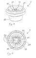
Figure 3 shows a perspective view of the pouring body of the closure ofFigure 1 ; -
Figure 4 shows a view from below of the pouring body ofFigure 3 . - Closure 1 can be fixed onto the
neck 101 of acontainer 100, such asneck 101 of a bottle, and comprises apouring body 2, anouter capsule 3 which fixesclosure 1 tocontainer 100, and aninner stopper 4, which is fixed toouter capsule 3 and which, when fitted tocontainer 100, can prevent the outflow of oil fromcontainer 100.Outer capsule 3 is generally composed of a stopper 5 and askirt 6, joined together along abreakable line 7. In an alternative embodiment,inner stopper 4 and stopper 5 are formed in one piece. -
Inner stopper 4 and pouringbody 2 comprise snap-fitting mutual engagement means 8, which fix them together beforeclosure 1 is fitted oncontainer 100. - According to the invention,
inner stopper 4 and pouringbody 2 are shaped so that the force required for engagement of mutual engagement means 8 is greater than the force which can be exerted on them by the reclosing ofclosure 1. - In other words, mutual engagement means 8 are engaged with each other before the initial opening, but after they have been separated by the initial opening it is no longer possible to engage them with each other by the normal operations of opening and
closing closure 1 according to the present invention. - During the reclosing operation,
inner stopper 4 is longitudinally moved towards pouringbody 2 and therefore mutual engagement means 8 are brought closer together. - The maximum force that mutual engagement means 8 can exchange with each other depends on the strength of the material of
inner stopper 4 and of pouringbody 2; this strength is chosen in such a way that the maximum force that can be exerted is lower than the minimum force required for the engagement of mutual engagement means 8. - Advantageously, mutual engagement means 8 engage with each other along the longitudinal direction X-X, defined by longitudinal axis X-X of
container 100 and ofneck 101 thereof. - When stopper 5 and
inner stopper 4 are separated from the rest of closure 1 (in the course of production, for example, or afterclosure 1 has been opened),inner stopper 4 and stopper 5 can be separated by a distance D other than zero in the longitudinal direction X-X, in the proximity of the position of said mutual engagement means 8; D can be substantially equal to or greater than the length L of the longitudinal portion of the mutual engagement means 8 which is in engagement before the initial opening. - This ensures that the deformability of
inner stopper 4, which prevents engagement of mutual engagement means 8, is not limited by the presence of stopper 5, which must be more rigid thaninner stopper 4. - In this preferred embodiment,
inner stopper 4 comprises a portion 10 whose deformability in longitudinal direction X-X is substantially greater than the deformability of the other parts; advantageously, such a highly deformable portion 10 is shaped in the form of a bellows and/or a bell. Thus it is possible to form stopper 5 andinner stopper 4 so that they are separate but fixed together. - In an alternative preferred embodiment (not shown in the drawings), the highly deformable portion 10 is formed in
pouring body 2. This second embodiment makes it possible, for example, to forminner stopper 4 in one piece with stopper 5.
The higher deformability can also be achieved, for example, by using portions of wall 10a and 10b ofinner stopper 4 and/or of pouringbody 2 which have a reduced thickness; the high deformability is substantially achieved by suitable shaping and reduction of the thickness ofinner stopper 4 and/or of pouringbody 2 respectively. - With reference to the embodiment shown in the drawing, mutual engagement means 8 comprise a female element 11, formed on
inner stopper 4, and a male element 12, formed onpouring body 2. However, the opposite configuration, which is equivalent to the above, can also be used. - The male element 12 comprises a
stem 13 and a flaredportion 14 which becomes wider in the longitudinal direction X-X towards saidinner stopper 4, while female element 11 can comprise acavity 15 which becomes narrower in the longitudinal direction X-X towardspouring body 2. Advantageously, the volume ofcavity 15 is such that it can contain flaredportion 14; in other words, it is greater than the volume of this portion. - As shown in the drawings, mutual engagement means 8 can be positioned substantially in the centre of the
closure 1 and/or there can be asingle stem 13 coaxial with the longitudinal axis X-X - Pouring
body 2 can also comprise acentral portion 16, which is advantageously dome-shaped, and which, whenclosure 1 is fitted oncontainer 100, is at least partially inserted intoneck 101 ofcontainer 100 and preferably lies completely inside pouringlip 17 of pouring body 2 (with respect to the longitudinal direction), - In the embodiment shown in the drawings, this
central portion 16 is connected tolateral portion 18 ofpouring body 2 byribs 19 which define four correspondingradial apertures 20 for the outflow of liquid from the interior ofcontainer 100 - Advantageously, the outer diameter of
central portion 16 and the inner diameter oflateral portion 18 are substantially equal, andradial apertures 20 are formed along a substantially cylindrical or slightly conical surface. - In the embodiment shown in the drawings, there are four
ribs 19; clearly, the number ofribs 19 can be different, for example three, five, six or more, - As shown in
Figures 1 and 2 , connectingribs 19 extend radially for a distance which may be as much as twice the thickness ofcentral portion 16, so as to form blades which provide better shaping of the flow of liquid out ofcontainer 100. - This configuration, which is particularly advantageous, also makes it possible to provide a particularly regular outflow of liquid in the case of oil, acting in a highly effective way to counteract the "surge" phenomenon described above,
- As shown in
Figure 2 , the outer diameter ofcentral portion 16 and the inner diameter oflateral portion 18 are substantially equal, andradial apertures 20 are formed along a substantially cylindrical or slightly conical surface. - Pouring
body 2 and/orinner stopper 4 can be made from polymer material, for example PE, by injection moulding for example; on the other hand, stopper 5 andskirt 6 can be made from drawn aluminium. - Clearly, if
inner stopper 4 and stopper 5 are formed in one piece, they can be made from the same materials, and by the same methods as those described previously with reference toinner stopper 4. - Since the effect of
closure 1 according to the present embodiment is to prevent a simple connection ofinner stopper 4 to pouringbody 2, it must be assembled by exerting a force between the mutual engagement means 8 in the longitudinal direction X-X which must be obtained by using a support which is separate fromclosure 1. - The support for pouring
body 2 and/or forinner stopper 4 enables mutual engagement means 8 to be fully engaged by snap-fitting, after which the support is removed. - When
closure 1 has been assembled, it can be fitted onmouth 102 of acontainer 100 having aneck 101 and amouth 102, andskirt 6 ofclosure 1 can then be rolled on so as to securely fixclosure 1 tocontainer 100. Whenclosure 1 is reclosed, the deformability ofinner stopper 4 and/or of pouringbody 2 can prevent the transmission between them of a sufficient force for mutual engagement means 8 to mutually engage anew, even when stopper 5 is fully screwed ontocontainer 100. - Clearly, a person skilled in the art can make numerous modifications and variations to the configurations described above, in order to meet contingent and specific requirements, all such modifications and variations being contained within the scope of protection of the invention as defined in the following claims.
Claims (12)
- A closure (1) suitable for being fixed to the neck (101) of a container (100) having a neck (101), such as a bottle, said closure (1) comprising:- a pouring body (2),- an outer capsule (3), for fixing the closure (1) to said container (100), comprising a stopper (5) connected to a skirt (6) by a breakable line (7);- an inner stopper (4), securely fixed to or made in one piece with said stopper (5), and capable of preventing the outflow of liquid from said container (100) when fitted on said container (100);- said inner stopper (4) and said pouring body (2) comprising snap-fitting mutual engagement means (8) which fix them to each other before said closure (1) is fitted on said container (100),characterized in that
said inner stopper (4) and said pouring body (2) are shaped in such a way that the force required for the engagement of said mutual engagement means (8) is greater than the force which can be exerted on them by reclosing said closure (1). - A closure (1) according to the preceding claim, in which, when the stopper (5) and the inner stopper (4) are at rest, in other words when they are separated from the rest of the closure (1), said inner stopper (4) and said stopper (5) are separated from each other, in the proximity of the position of said mutual engagement means (8), by a distance D, which is substantially equal to or greater than the length of the engagement portion by which the mutual engagement means (8) are in engagement before the initial opening.
- A closure (1) according to either one of the preceding claims, in which said inner stopper (4) and/or said pouring body (2) comprise a portion (10) whose deformability in the longitudinal direction (X-X) is substantially greater than the deformability of the other parts.
- A closure (1) according to the preceding claim, in which said highly deformable portion (10) is shaped in the form of a bellows and/or a bell.
- A closure (1) according to any one of the preceding claims, in which said mutual engagement means (8) comprise a female element (11), formed on the inner stopper (4), and a male element (12), formed on the pouring body (2).
- A closure (1) according to the preceding claim, in which said male element (12) comprises a stem (13) and a flared portion (14) which becomes wider in the longitudinal direction (X-X) towards said inner stopper (4).
- A closure (1) according to any one of the preceding claims, in which said mutual engagement means (8) are positioned substantially in the centre of said closure (1)
- A closure (1) according to any one of the preceding claims, in which said pouring body (2) and/or said stopper (4) are made from polymer material.
- A closure (1) according to any one of the preceding claims, in which said outer capsule (3) is made from drawn aluminium.
- A method of assembling a closure (1) according to any one of the preceding claims, comprising the steps of:a) providing a pouring body (2) and an inner stopper (4) according to any one of the preceding claims;b) providing a support in the longitudinal direction (X-X) for the pouring body (2) and/or for the inner stopper (4);c) supporting the pouring body (2) and/or the inner stopper (4) in the longitudinal direction (X-X) by means of the support;d) bringing the pouring body (2) and/or the inner stopper (4) towards each other in the longitudinal direction (X-X) until the snap-fitting mutual engagement means (8) are fully engaged;e) removing the support.
- A method according to the preceding claim, additionally comprising the step of:e) fitting the closure (1) according to any one of Claims 1 to 6 to the mouth of a container (100) provided with a neck (101) and a mouth, after steps a), b), c) and d).
- A method according to either claim 10 or claim 11, additionally comprising the step of:g) rolling the skirt (6) of said closure (1) so as to fix it securely to said container (100).
Applications Claiming Priority (1)
| Application Number | Priority Date | Filing Date | Title |
|---|---|---|---|
| IT001310A ITMI20071310A1 (en) | 2007-06-29 | 2007-06-29 | OIL TAPER. |
Publications (2)
| Publication Number | Publication Date |
|---|---|
| EP2008942A1 true EP2008942A1 (en) | 2008-12-31 |
| EP2008942B1 EP2008942B1 (en) | 2010-09-15 |
Family
ID=39790342
Family Applications (1)
| Application Number | Title | Priority Date | Filing Date |
|---|---|---|---|
| EP08155012A Active EP2008942B1 (en) | 2007-06-29 | 2008-04-23 | An oil pourer |
Country Status (5)
| Country | Link |
|---|---|
| EP (1) | EP2008942B1 (en) |
| AT (1) | ATE481329T1 (en) |
| DE (1) | DE602008002480D1 (en) |
| ES (1) | ES2353036T3 (en) |
| IT (1) | ITMI20071310A1 (en) |
Cited By (4)
| Publication number | Priority date | Publication date | Assignee | Title |
|---|---|---|---|---|
| WO2013005181A1 (en) * | 2011-07-05 | 2013-01-10 | Andries Jacobus Rabie | A dispensing container and nozzle for dispensing a consumable oil-containing liquid |
| EP3093256A1 (en) | 2015-05-11 | 2016-11-16 | Labrenta S.r.l. | Antifilling pourer for bottle |
| WO2018168283A1 (en) * | 2017-03-17 | 2018-09-20 | 東洋製罐株式会社 | Sealing structure for cap |
| CN110546077A (en) * | 2017-03-15 | 2019-12-06 | 日本克乐嘉制盖株式会社 | Composite container cover |
Citations (4)
| Publication number | Priority date | Publication date | Assignee | Title |
|---|---|---|---|---|
| FR2271134A1 (en) * | 1974-05-17 | 1975-12-12 | Bouchage Mecanique | Pilfer proof closure for bottle with plain neck - has non-drip pourer and stopper in bottle neck and foil cover with tear off strip |
| IT207976Z2 (en) | 1986-07-16 | 1988-03-14 | Cap Vit Spa | LUIDI POURING DEVICE MOUNTED ON THE MOUTH OF BOTTLE TYPE CONTAINERS. |
| GB2280895A (en) * | 1993-08-04 | 1995-02-15 | Malcolm Gordon Victory | Closure devices with compressible core seal |
| GB2296911A (en) * | 1995-01-12 | 1996-07-17 | Guala Uk Ltd | Tamper evident closure with pourer for a bottle |
-
2007
- 2007-06-29 IT IT001310A patent/ITMI20071310A1/en unknown
-
2008
- 2008-04-23 ES ES08155012T patent/ES2353036T3/en active Active
- 2008-04-23 AT AT08155012T patent/ATE481329T1/en not_active IP Right Cessation
- 2008-04-23 EP EP08155012A patent/EP2008942B1/en active Active
- 2008-04-23 DE DE602008002480T patent/DE602008002480D1/en active Active
Patent Citations (4)
| Publication number | Priority date | Publication date | Assignee | Title |
|---|---|---|---|---|
| FR2271134A1 (en) * | 1974-05-17 | 1975-12-12 | Bouchage Mecanique | Pilfer proof closure for bottle with plain neck - has non-drip pourer and stopper in bottle neck and foil cover with tear off strip |
| IT207976Z2 (en) | 1986-07-16 | 1988-03-14 | Cap Vit Spa | LUIDI POURING DEVICE MOUNTED ON THE MOUTH OF BOTTLE TYPE CONTAINERS. |
| GB2280895A (en) * | 1993-08-04 | 1995-02-15 | Malcolm Gordon Victory | Closure devices with compressible core seal |
| GB2296911A (en) * | 1995-01-12 | 1996-07-17 | Guala Uk Ltd | Tamper evident closure with pourer for a bottle |
Cited By (8)
| Publication number | Priority date | Publication date | Assignee | Title |
|---|---|---|---|---|
| WO2013005181A1 (en) * | 2011-07-05 | 2013-01-10 | Andries Jacobus Rabie | A dispensing container and nozzle for dispensing a consumable oil-containing liquid |
| EP3093256A1 (en) | 2015-05-11 | 2016-11-16 | Labrenta S.r.l. | Antifilling pourer for bottle |
| CN110546077A (en) * | 2017-03-15 | 2019-12-06 | 日本克乐嘉制盖株式会社 | Composite container cover |
| EP3597559A4 (en) * | 2017-03-15 | 2021-01-20 | Nippon Closures Co., Ltd. | Composite container lid |
| TWI756379B (en) * | 2017-03-15 | 2022-03-01 | 日商日本克樂嘉製蓋股份有限公司 | Composite lid for containers |
| US11325758B2 (en) | 2017-03-15 | 2022-05-10 | Nippon Closures Co., Ltd. | Composite container lid |
| WO2018168283A1 (en) * | 2017-03-17 | 2018-09-20 | 東洋製罐株式会社 | Sealing structure for cap |
| JP2018154373A (en) * | 2017-03-17 | 2018-10-04 | 東洋製罐株式会社 | Cap sealing structure |
Also Published As
| Publication number | Publication date |
|---|---|
| EP2008942B1 (en) | 2010-09-15 |
| ATE481329T1 (en) | 2010-10-15 |
| ITMI20071310A1 (en) | 2008-12-30 |
| ES2353036T3 (en) | 2011-02-24 |
| DE602008002480D1 (en) | 2010-10-28 |
Similar Documents
| Publication | Publication Date | Title |
|---|---|---|
| EP2248732B1 (en) | Closure body | |
| EP1867574B1 (en) | A closure assembly having a spout with a memory band for spout directing | |
| US6050435A (en) | Closure with integral self-sealing silicone valve and method for making same | |
| JP2004196417A (en) | Nozzle structure for liquid container | |
| EP3487774B1 (en) | Tamper evident closure | |
| US5588546A (en) | Closure with stay-open lid | |
| EP2008942B1 (en) | An oil pourer | |
| EP1860037A1 (en) | Spout fitting and container | |
| EP3259198B1 (en) | Internal threaded tube | |
| EP3873820A1 (en) | Closure for a spout of a flexible thin-walled package | |
| US5961010A (en) | Dispensing beverage closure | |
| CN108137196B (en) | Closure cap for a liquid container with discharge regulation | |
| US5573147A (en) | Container in combination with a removable cap | |
| JP4916806B2 (en) | Container with cap | |
| MXPA03002883A (en) | Positive-orientation systems for closures and containers. | |
| US20040112919A1 (en) | Closure with integrated ventilation | |
| JP5171358B2 (en) | Dispensing inner stopper | |
| US20190233272A1 (en) | Internally locking funnel assembly for container with plastic press-in closure | |
| JP5154293B2 (en) | Spout | |
| JP2021075331A (en) | Moving inner plug cap | |
| JP5102098B2 (en) | Spout | |
| JP2010006396A (en) | Cap | |
| JP5086128B2 (en) | Dispensing inner stopper | |
| JP2004083035A (en) | Container cap with valve | |
| MXPA96000074A (en) | Provision for a can container with upper separate opening |
Legal Events
| Date | Code | Title | Description |
|---|---|---|---|
| PUAI | Public reference made under article 153(3) epc to a published international application that has entered the european phase |
Free format text: ORIGINAL CODE: 0009012 |
|
| AK | Designated contracting states |
Kind code of ref document: A1 Designated state(s): AT BE BG CH CY CZ DE DK EE ES FI FR GB GR HR HU IE IS IT LI LT LU LV MC MT NL NO PL PT RO SE SI SK TR |
|
| AX | Request for extension of the european patent |
Extension state: AL BA MK RS |
|
| 17P | Request for examination filed |
Effective date: 20090120 |
|
| 17Q | First examination report despatched |
Effective date: 20090220 |
|
| AKX | Designation fees paid |
Designated state(s): AT BE BG CH CY CZ DE DK EE ES FI FR GB GR HR HU IE IS IT LI LT LU LV MC MT NL NO PL PT RO SE SI SK TR |
|
| GRAP | Despatch of communication of intention to grant a patent |
Free format text: ORIGINAL CODE: EPIDOSNIGR1 |
|
| GRAS | Grant fee paid |
Free format text: ORIGINAL CODE: EPIDOSNIGR3 |
|
| GRAA | (expected) grant |
Free format text: ORIGINAL CODE: 0009210 |
|
| AK | Designated contracting states |
Kind code of ref document: B1 Designated state(s): AT BE BG CH CY CZ DE DK EE ES FI FR GB GR HR HU IE IS IT LI LT LU LV MC MT NL NO PL PT RO SE SI SK TR |
|
| REG | Reference to a national code |
Ref country code: GB Ref legal event code: FG4D Ref country code: CH Ref legal event code: EP |
|
| REG | Reference to a national code |
Ref country code: IE Ref legal event code: FG4D |
|
| REF | Corresponds to: |
Ref document number: 602008002480 Country of ref document: DE Date of ref document: 20101028 Kind code of ref document: P |
|
| REG | Reference to a national code |
Ref country code: NL Ref legal event code: VDEP Effective date: 20100915 |
|
| PG25 | Lapsed in a contracting state [announced via postgrant information from national office to epo] |
Ref country code: NO Free format text: LAPSE BECAUSE OF FAILURE TO SUBMIT A TRANSLATION OF THE DESCRIPTION OR TO PAY THE FEE WITHIN THE PRESCRIBED TIME-LIMIT Effective date: 20101215 Ref country code: LT Free format text: LAPSE BECAUSE OF FAILURE TO SUBMIT A TRANSLATION OF THE DESCRIPTION OR TO PAY THE FEE WITHIN THE PRESCRIBED TIME-LIMIT Effective date: 20100915 Ref country code: FI Free format text: LAPSE BECAUSE OF FAILURE TO SUBMIT A TRANSLATION OF THE DESCRIPTION OR TO PAY THE FEE WITHIN THE PRESCRIBED TIME-LIMIT Effective date: 20100915 Ref country code: AT Free format text: LAPSE BECAUSE OF FAILURE TO SUBMIT A TRANSLATION OF THE DESCRIPTION OR TO PAY THE FEE WITHIN THE PRESCRIBED TIME-LIMIT Effective date: 20100915 |
|
| REG | Reference to a national code |
Ref country code: ES Ref legal event code: FG2A Effective date: 20110214 |
|
| LTIE | Lt: invalidation of european patent or patent extension |
Effective date: 20100915 |
|
| PG25 | Lapsed in a contracting state [announced via postgrant information from national office to epo] |
Ref country code: HR Free format text: LAPSE BECAUSE OF FAILURE TO SUBMIT A TRANSLATION OF THE DESCRIPTION OR TO PAY THE FEE WITHIN THE PRESCRIBED TIME-LIMIT Effective date: 20100915 Ref country code: SI Free format text: LAPSE BECAUSE OF FAILURE TO SUBMIT A TRANSLATION OF THE DESCRIPTION OR TO PAY THE FEE WITHIN THE PRESCRIBED TIME-LIMIT Effective date: 20100915 Ref country code: PL Free format text: LAPSE BECAUSE OF FAILURE TO SUBMIT A TRANSLATION OF THE DESCRIPTION OR TO PAY THE FEE WITHIN THE PRESCRIBED TIME-LIMIT Effective date: 20100915 Ref country code: CY Free format text: LAPSE BECAUSE OF FAILURE TO SUBMIT A TRANSLATION OF THE DESCRIPTION OR TO PAY THE FEE WITHIN THE PRESCRIBED TIME-LIMIT Effective date: 20100915 |
|
| PG25 | Lapsed in a contracting state [announced via postgrant information from national office to epo] |
Ref country code: GR Free format text: LAPSE BECAUSE OF FAILURE TO SUBMIT A TRANSLATION OF THE DESCRIPTION OR TO PAY THE FEE WITHIN THE PRESCRIBED TIME-LIMIT Effective date: 20101216 Ref country code: SE Free format text: LAPSE BECAUSE OF FAILURE TO SUBMIT A TRANSLATION OF THE DESCRIPTION OR TO PAY THE FEE WITHIN THE PRESCRIBED TIME-LIMIT Effective date: 20100915 Ref country code: LV Free format text: LAPSE BECAUSE OF FAILURE TO SUBMIT A TRANSLATION OF THE DESCRIPTION OR TO PAY THE FEE WITHIN THE PRESCRIBED TIME-LIMIT Effective date: 20100915 |
|
| PG25 | Lapsed in a contracting state [announced via postgrant information from national office to epo] |
Ref country code: IS Free format text: LAPSE BECAUSE OF FAILURE TO SUBMIT A TRANSLATION OF THE DESCRIPTION OR TO PAY THE FEE WITHIN THE PRESCRIBED TIME-LIMIT Effective date: 20110115 Ref country code: NL Free format text: LAPSE BECAUSE OF FAILURE TO SUBMIT A TRANSLATION OF THE DESCRIPTION OR TO PAY THE FEE WITHIN THE PRESCRIBED TIME-LIMIT Effective date: 20100915 Ref country code: RO Free format text: LAPSE BECAUSE OF FAILURE TO SUBMIT A TRANSLATION OF THE DESCRIPTION OR TO PAY THE FEE WITHIN THE PRESCRIBED TIME-LIMIT Effective date: 20100915 Ref country code: CZ Free format text: LAPSE BECAUSE OF FAILURE TO SUBMIT A TRANSLATION OF THE DESCRIPTION OR TO PAY THE FEE WITHIN THE PRESCRIBED TIME-LIMIT Effective date: 20100915 Ref country code: EE Free format text: LAPSE BECAUSE OF FAILURE TO SUBMIT A TRANSLATION OF THE DESCRIPTION OR TO PAY THE FEE WITHIN THE PRESCRIBED TIME-LIMIT Effective date: 20100915 Ref country code: PT Free format text: LAPSE BECAUSE OF FAILURE TO SUBMIT A TRANSLATION OF THE DESCRIPTION OR TO PAY THE FEE WITHIN THE PRESCRIBED TIME-LIMIT Effective date: 20110117 Ref country code: SK Free format text: LAPSE BECAUSE OF FAILURE TO SUBMIT A TRANSLATION OF THE DESCRIPTION OR TO PAY THE FEE WITHIN THE PRESCRIBED TIME-LIMIT Effective date: 20100915 |
|
| PG25 | Lapsed in a contracting state [announced via postgrant information from national office to epo] |
Ref country code: BE Free format text: LAPSE BECAUSE OF FAILURE TO SUBMIT A TRANSLATION OF THE DESCRIPTION OR TO PAY THE FEE WITHIN THE PRESCRIBED TIME-LIMIT Effective date: 20100915 |
|
| PLBE | No opposition filed within time limit |
Free format text: ORIGINAL CODE: 0009261 |
|
| STAA | Information on the status of an ep patent application or granted ep patent |
Free format text: STATUS: NO OPPOSITION FILED WITHIN TIME LIMIT |
|
| 26N | No opposition filed |
Effective date: 20110616 |
|
| PG25 | Lapsed in a contracting state [announced via postgrant information from national office to epo] |
Ref country code: DK Free format text: LAPSE BECAUSE OF FAILURE TO SUBMIT A TRANSLATION OF THE DESCRIPTION OR TO PAY THE FEE WITHIN THE PRESCRIBED TIME-LIMIT Effective date: 20100915 |
|
| REG | Reference to a national code |
Ref country code: DE Ref legal event code: R097 Ref document number: 602008002480 Country of ref document: DE Effective date: 20110616 |
|
| PG25 | Lapsed in a contracting state [announced via postgrant information from national office to epo] |
Ref country code: MC Free format text: LAPSE BECAUSE OF NON-PAYMENT OF DUE FEES Effective date: 20110430 |
|
| PG25 | Lapsed in a contracting state [announced via postgrant information from national office to epo] |
Ref country code: MT Free format text: LAPSE BECAUSE OF FAILURE TO SUBMIT A TRANSLATION OF THE DESCRIPTION OR TO PAY THE FEE WITHIN THE PRESCRIBED TIME-LIMIT Effective date: 20100915 |
|
| REG | Reference to a national code |
Ref country code: FR Ref legal event code: ST Effective date: 20111230 |
|
| PG25 | Lapsed in a contracting state [announced via postgrant information from national office to epo] |
Ref country code: FR Free format text: LAPSE BECAUSE OF NON-PAYMENT OF DUE FEES Effective date: 20110502 Ref country code: DE Free format text: LAPSE BECAUSE OF NON-PAYMENT OF DUE FEES Effective date: 20111101 |
|
| REG | Reference to a national code |
Ref country code: IE Ref legal event code: MM4A |
|
| REG | Reference to a national code |
Ref country code: DE Ref legal event code: R119 Ref document number: 602008002480 Country of ref document: DE Effective date: 20111101 |
|
| PG25 | Lapsed in a contracting state [announced via postgrant information from national office to epo] |
Ref country code: IE Free format text: LAPSE BECAUSE OF NON-PAYMENT OF DUE FEES Effective date: 20110423 |
|
| REG | Reference to a national code |
Ref country code: CH Ref legal event code: PL |
|
| GBPC | Gb: european patent ceased through non-payment of renewal fee |
Effective date: 20120423 |
|
| PG25 | Lapsed in a contracting state [announced via postgrant information from national office to epo] |
Ref country code: GB Free format text: LAPSE BECAUSE OF NON-PAYMENT OF DUE FEES Effective date: 20120423 Ref country code: LI Free format text: LAPSE BECAUSE OF NON-PAYMENT OF DUE FEES Effective date: 20120430 Ref country code: CH Free format text: LAPSE BECAUSE OF NON-PAYMENT OF DUE FEES Effective date: 20120430 |
|
| PG25 | Lapsed in a contracting state [announced via postgrant information from national office to epo] |
Ref country code: LU Free format text: LAPSE BECAUSE OF NON-PAYMENT OF DUE FEES Effective date: 20110423 |
|
| PG25 | Lapsed in a contracting state [announced via postgrant information from national office to epo] |
Ref country code: BG Free format text: LAPSE BECAUSE OF FAILURE TO SUBMIT A TRANSLATION OF THE DESCRIPTION OR TO PAY THE FEE WITHIN THE PRESCRIBED TIME-LIMIT Effective date: 20101215 Ref country code: TR Free format text: LAPSE BECAUSE OF FAILURE TO SUBMIT A TRANSLATION OF THE DESCRIPTION OR TO PAY THE FEE WITHIN THE PRESCRIBED TIME-LIMIT Effective date: 20100915 |
|
| PG25 | Lapsed in a contracting state [announced via postgrant information from national office to epo] |
Ref country code: HU Free format text: LAPSE BECAUSE OF FAILURE TO SUBMIT A TRANSLATION OF THE DESCRIPTION OR TO PAY THE FEE WITHIN THE PRESCRIBED TIME-LIMIT Effective date: 20100915 |
|
| P01 | Opt-out of the competence of the unified patent court (upc) registered |
Effective date: 20230602 |
|
| PGFP | Annual fee paid to national office [announced via postgrant information from national office to epo] |
Ref country code: IT Payment date: 20230428 Year of fee payment: 16 Ref country code: ES Payment date: 20230627 Year of fee payment: 16 |
|
| P02 | Opt-out of the competence of the unified patent court (upc) changed |
Effective date: 20230818 |