EP2008798B1 - Tyre building drum - Google Patents
Tyre building drum Download PDFInfo
- Publication number
- EP2008798B1 EP2008798B1 EP08153853A EP08153853A EP2008798B1 EP 2008798 B1 EP2008798 B1 EP 2008798B1 EP 08153853 A EP08153853 A EP 08153853A EP 08153853 A EP08153853 A EP 08153853A EP 2008798 B1 EP2008798 B1 EP 2008798B1
- Authority
- EP
- European Patent Office
- Prior art keywords
- building drum
- segments
- piston
- annular
- supporting body
- Prior art date
- Legal status (The legal status is an assumption and is not a legal conclusion. Google has not performed a legal analysis and makes no representation as to the accuracy of the status listed.)
- Not-in-force
Links
Images




Classifications
-
- B—PERFORMING OPERATIONS; TRANSPORTING
- B29—WORKING OF PLASTICS; WORKING OF SUBSTANCES IN A PLASTIC STATE IN GENERAL
- B29D—PRODUCING PARTICULAR ARTICLES FROM PLASTICS OR FROM SUBSTANCES IN A PLASTIC STATE
- B29D30/00—Producing pneumatic or solid tyres or parts thereof
- B29D30/06—Pneumatic tyres or parts thereof (e.g. produced by casting, moulding, compression moulding, injection moulding, centrifugal casting)
- B29D30/08—Building tyres
- B29D30/20—Building tyres by the flat-tyre method, i.e. building on cylindrical drums
- B29D30/24—Drums
- B29D30/244—Drums for manufacturing substantially cylindrical tyre components with cores or beads, e.g. carcasses
- B29D30/245—Drums for the single stage building process, i.e. the building-up of the cylindrical carcass and the toroidal expansion of it are realised on the same drum
Definitions
- the present invention relates to a tyre building drum according to the preamble of claim 1.
- Conventional tyre manufacturing employs a first-stage building drum, on which the various parts of the tyre are applied successively to form a cylindrical carcass; and the cylindrical carcass is transferred to an expandible second-stage building drum, on which the cylindrical carcass is expanded centrally into a toroidal shape and fitted with the remaining parts of the tyre (belts and tread).
- conventional tyre manufacturing employs two separate building drums, and calls for transferring the carcass from one drum to the other.
- a single-stage building drum has been proposed, on which to both assemble and expand the carcass.
- a single-stage building drum is of complex design, by having to expand and contract both axially and radially.
- a single-stage building drum such as the one described, for example, in Patent Application EP1674248 , is supported on a central shaft mounted to rotate about a longitudinal axis of rotation, and comprises two specularly identical half-drums (one right and one left) movable axially to and from each other (i.e. parallel to the longitudinal axis of rotation).
- each half-drum comprises a lateral section with a bead locking device, which is also movable radially (i.e. perpendicular to the longitudinal axis of rotation) to expand or contract; and a central section, which is also movable radially to expand or contract independently of the bead locking device.
- Each central section comprises an annular supporting body supporting a number of segments equally spaced about and movable radially with respect to the supporting body.
- Each segment comprises a number of fingers spaced a given distance apart to define, between each two adjacent fingers, a recess of at least the same width as a finger.
- the fingers of the segments of one central section are positioned facing and aligned with the recesses of the segments of the other central section, so that each finger slides freely inside a respective recess between two fingers on the other central section, and the fingers of the segments interlace when the two central sections are brought together.
- Both the central sections are covered with a toroidal, deformable, flexible former bladder (or sleeve) fixed laterally to each supporting body by a fastening ring screwed to an outer lateral wall of the supporting body.
- the former bladder is inflated with compressed air to impart a toroidal shape to the carcass of the tyre being built.
- the former bladder and possibly also the segments of the two central sections must be changed. Whichever the case, the former bladder must always be removed from the central sections, which means removing the former bladder fastening rings. This is a complicated, time-consuming job, which involves removing the lateral sections to remove the fastening ring screws from the outer lateral walls of the supporting bodies of the central sections.
- Number 1 in Figures 1 and 2 indicates as a whole a single-stage building drum supported on a central shaft 2 ( Figure 5 ) mounted to rotate about a longitudinal axis of rotation 3.
- Building drum 1 comprises two specularly identical half-drums 4 movable to and from each other axially (i.e. parallel to longitudinal axis of rotation 3). That is, each half-drum 4 is mounted on a slide to slide axially, with respect to central shaft 2, under the control of a pneumatic actuator.
- each half-drum 4 comprises a lateral section 5 with a bead locking device 6, which is also movable radially (i.e. perpendicular to longitudinal axis of rotation 3) to expand or contract; and a central section 7, which is also movable radially to expand or contract independently of bead locking device 6.
- each central section 7 comprises an annular supporting body 8 supporting a number of segments 9 equally spaced about and movable radially with respect to supporting body 8.
- Each segment 9 comprises a number of fingers 10 spaced a given distance apart to define, between each two adjacent fingers 10, a recess 11 ( Figure 1 ) of at least the same width as a finger 10.
- the fingers 10 of segments 9 of one central section 7 are positioned facing and aligned with the recesses 11 of segments 9 of the other central section 7, so that each finger 10 slides freely inside a respective recess 11 between two fingers 10 on the other central section 7, and the fingers 10 of segments 9 interlace when the two central sections 7 are brought together.
- Both the central sections 7 are covered with a common toroidal, deformable, flexible former bladder 12 fixed laterally to each supporting body 8 by a fastening ring 13 screwed to an outer lateral wall 14 of supporting body 8 by screws 15.
- former bladder 12 is inflated with compressed air to impart a toroidal shape to the carcass of the tyre being built.
- Annular supporting body 8 has a number of cylindrical radial seats 16, each housing in sliding manner a piston 17 supporting a segment 9. More specifically, each segment 9 is screwed to piston 17 by two radial screws 18 (only one shown in Figure 4 ); and each piston 17 is moved radially along cylindrical radial seat 16 by a pneumatic actuating device 19 connected mechanically to piston 17 by a curved transmission lever 20.
- pneumatic actuating device 19 comprises an annular actuating body 21, in which are defined two annular chambers 22a, 22b, in which respective integral pistons 23a, 23b slide axially; and each curved transmission lever 20 is hinged at one end to piston 23b, and at the other end to piston 17.
- the two chambers 22a, 22b of pneumatic actuating device 19 operate in series, and are connectable by respective solenoid valves to a compressed-air source to move pistons 23 towards the centre of building drum 1 and so move segments 9 away from shaft 2, or are connectable by the respective solenoid valves to a vacuum source to move pistons 23 towards the periphery of building drum 1, and so move segments 9 towards shaft 2.
- actuating device 19 comprises one annular chamber 22, along which one piston 23 slides.
- Each lateral section 5 comprises an annular supporting body 24 mounted to slide axially, on annular actuating body 21 of pneumatic actuating device 19, between a work position ( Figure 2 ) and a maintenance position ( Figure 3 ).
- annular supporting body 24 in the work position, is locked to annular actuating body 21 of pneumatic actuating device 19 by a number of radial lock screws 25 (only one shown in Figure 4 ).
- Each annular supporting body 24 supports an inflatable annular bag 26 connectable by a respective solenoid valve to a compressed-air source for inflation, or to a vacuum source for deflation.
- each supporting body 24 has a number of cylindrical radial seats 27, each housing in sliding manner a piston 28 supporting a segment 29; segments 29 all combine to define bead locking device 6; and each piston 28 is moved radially along cylindrical radial seat 27 by a pneumatic actuating device 30 connected mechanically to piston 28 by a connecting wedge 31.
- Pneumatic actuating device 30 comprises an annular chamber 32 formed inside supporting body 24, and along which a piston 33, integral with connecting wedge 31, slides axially.
- a piston 33 integral with connecting wedge 31, slides axially.
- the bottom portion of each piston 28 is preferably fitted with an idle roller 34 which rolls along the sloping surface of connecting wedge 31.
- Chamber 32 of pneumatic actuating device 30 is connectable by a respective solenoid valve to a compressed-air source to move pistons 33 outwards of building drum 1 and so move segments 29 away from shaft 2, or is connectable by the respective solenoid valve to a vacuum source to move pistons 33 inwards of building drum 1, and so move segments 29 towards shaft 2.
- former bladder 12 and possibly also segments 9 of the two central sections 7 must be changed. Whichever the case, former bladder 12 must always be removed from central sections 7, which means removing fastening rings 13 of former bladder 12.
- lateral sections 5 To remove/assemble fastening rings 13 of former bladder 12, lateral sections 5 must be withdrawn from central sections 7 to remove/tighten screws 15 of fastening rings 13 from/to the outer lateral walls 14 of supporting bodies 8 of central sections 7. Lateral sections 5 are withdrawn from central sections 7 by simply moving the two supporting bodies 24 of lateral sections 5 from the work position ( Figure 2 ) to the maintenance position ( Figure 3 ), which can be done quickly and easily, by virtue of each supporting body 24 being mounted to slide axially on actuating body 21 of pneumatic actuating device 19. In other words, by simply loosening (or removing) lock screws 25 securing each supporting body 24 to actuating body 21 of pneumatic actuating device 19 underneath, and then pushing supporting body 24 manually outwards.
- former bladder 12 of building drum 1 described above can be changed 70% faster than that of a similar conventional building drum.
- segments 9 may also be changed quickly and easily, by virtue of screws 15 of segments 9 being clearly visible and accessible from the outside once former bladder 12 is removed.
- segments 9 are not all alike, but divided into two alternating types, i.e. outer segments 9a alternating with inner segments 9b.
- Each outer segment 9a has a trapezoidal section with a circular outer major base, so that a recess is formed, between each two adjacent outer segments 9a, in which to fit an inner segment 9b, which has a trapezoidal section with an outer minor base.
- central sections 7 When segments 9 are in the contracted position, the outer surface of central sections 7 is defined solely by the union of the outer surfaces of outer segments 9a; conversely, when segments 9 expand, the gap formed between each two adjacent outer segments 9a is filled by an underlying inner segment 9b, so that, even in the expanded configuration, central sections 7 have a sufficiently even outer surface (i.e. with no major breaks) to effectively support the component parts of the tyre being formed.
- Bead locking devices 6 are then activated to lock beads 37 ( Figure 7 ).
- pre-forming is performed by inflating former bladder 12, bringing central sections 7 closer together axially, i.e. reducing the overall width of central sections 7 ( Figure 8 ), and expanding central sections 7 radially to adequately support sidewalls 35.
Landscapes
- Engineering & Computer Science (AREA)
- Manufacturing & Machinery (AREA)
- Mechanical Engineering (AREA)
- Tyre Moulding (AREA)
- Drying Of Solid Materials (AREA)
Description
- The present invention relates to a tyre building drum according to the preamble of
claim 1. - Conventional tyre manufacturing employs a first-stage building drum, on which the various parts of the tyre are applied successively to form a cylindrical carcass; and the cylindrical carcass is transferred to an expandible second-stage building drum, on which the cylindrical carcass is expanded centrally into a toroidal shape and fitted with the remaining parts of the tyre (belts and tread). In other words, conventional tyre manufacturing employs two separate building drums, and calls for transferring the carcass from one drum to the other.
- More recently, a single-stage building drum has been proposed, on which to both assemble and expand the carcass. A single-stage building drum, however, is of complex design, by having to expand and contract both axially and radially.
- A single-stage building drum, such as the one described, for example, in Patent Application
EP1674248 , is supported on a central shaft mounted to rotate about a longitudinal axis of rotation, and comprises two specularly identical half-drums (one right and one left) movable axially to and from each other (i.e. parallel to the longitudinal axis of rotation). - From the outside inwards, each half-drum comprises a lateral section with a bead locking device, which is also movable radially (i.e. perpendicular to the longitudinal axis of rotation) to expand or contract; and a central section, which is also movable radially to expand or contract independently of the bead locking device.
- Each central section comprises an annular supporting body supporting a number of segments equally spaced about and movable radially with respect to the supporting body. Each segment comprises a number of fingers spaced a given distance apart to define, between each two adjacent fingers, a recess of at least the same width as a finger. And the fingers of the segments of one central section are positioned facing and aligned with the recesses of the segments of the other central section, so that each finger slides freely inside a respective recess between two fingers on the other central section, and the fingers of the segments interlace when the two central sections are brought together.
- Both the central sections are covered with a toroidal, deformable, flexible former bladder (or sleeve) fixed laterally to each supporting body by a fastening ring screwed to an outer lateral wall of the supporting body. In actual use, the former bladder is inflated with compressed air to impart a toroidal shape to the carcass of the tyre being built.
- To change the size of the above building drum, i.e. the size of the tyres formed on the building drum, the former bladder and possibly also the segments of the two central sections must be changed. Whichever the case, the former bladder must always be removed from the central sections, which means removing the former bladder fastening rings. This is a complicated, time-consuming job, which involves removing the lateral sections to remove the fastening ring screws from the outer lateral walls of the supporting bodies of the central sections.
-
US2005279444A1 ,US4214939A1 ,WO2006033119A1 andJP07100954A independent claim 1. - It is an object of the present invention to provide a tyre building drum which is cheap and easy to produce, eliminates the aforementioned drawbacks, and, in particular, provides for making fast size changes.
- According to the present invention, there is provided a tyre building drum as claimed in the accompanying Claims.
- A non-limiting embodiment of the present invention will be described by way of example with reference to the accompanying drawings, in which:
-
Figure 1 shows a schematic view in perspective, with parts removed for clarity, of the central sections of a tyre building drum in accordance with the present invention; -
Figure 2 shows a schematic longitudinal section, with parts removed for clarity, of part of theFigure 1 building drum in a work configuration; -
Figure 3 shows a schematic longitudinal section, with parts removed for clarity, of part of theFigure 1 building drum in a size-change or maintenance configuration; -
Figure 4 shows a larger-scale view ofFigure 2 ; -
Figure 5 shows a schematic cross section, with parts removed for clarity, of a central section of the -
Figure 1 building drum in a contracted configuration and expanded configuration; -
Figures 6-10 show a succession of schematic longitudinal sections, with parts removed for clarity, of part of theFigure 1 building drum in the course of building a tyre. -
Number 1 inFigures 1 and2 indicates as a whole a single-stage building drum supported on a central shaft 2 (Figure 5 ) mounted to rotate about a longitudinal axis ofrotation 3.Building drum 1 comprises two specularly identical half-drums 4 movable to and from each other axially (i.e. parallel to longitudinal axis of rotation 3). That is, each half-drum 4 is mounted on a slide to slide axially, with respect tocentral shaft 2, under the control of a pneumatic actuator. - From the outside inwards, each half-
drum 4 comprises alateral section 5 with abead locking device 6, which is also movable radially (i.e. perpendicular to longitudinal axis of rotation 3) to expand or contract; and acentral section 7, which is also movable radially to expand or contract independently ofbead locking device 6. - As shown in
Figure 4 , eachcentral section 7 comprises an annular supportingbody 8 supporting a number ofsegments 9 equally spaced about and movable radially with respect to supportingbody 8. Eachsegment 9 comprises a number offingers 10 spaced a given distance apart to define, between each twoadjacent fingers 10, a recess 11 (Figure 1 ) of at least the same width as afinger 10. And thefingers 10 ofsegments 9 of onecentral section 7 are positioned facing and aligned with therecesses 11 ofsegments 9 of the othercentral section 7, so that eachfinger 10 slides freely inside arespective recess 11 between twofingers 10 on the othercentral section 7, and thefingers 10 ofsegments 9 interlace when the twocentral sections 7 are brought together. - Both the
central sections 7 are covered with a common toroidal, deformable, flexibleformer bladder 12 fixed laterally to each supportingbody 8 by a fasteningring 13 screwed to an outerlateral wall 14 of supportingbody 8 byscrews 15. In actual use,former bladder 12 is inflated with compressed air to impart a toroidal shape to the carcass of the tyre being built. - Annular supporting
body 8 has a number of cylindricalradial seats 16, each housing in sliding manner apiston 17 supporting asegment 9. More specifically, eachsegment 9 is screwed topiston 17 by two radial screws 18 (only one shown inFigure 4 ); and eachpiston 17 is moved radially along cylindricalradial seat 16 by apneumatic actuating device 19 connected mechanically topiston 17 by acurved transmission lever 20. - In a preferred embodiment,
pneumatic actuating device 19 comprises an annular actuatingbody 21, in which are defined twoannular chambers integral pistons curved transmission lever 20 is hinged at one end topiston 23b, and at the other end topiston 17. The twochambers pneumatic actuating device 19 operate in series, and are connectable by respective solenoid valves to a compressed-air source to move pistons 23 towards the centre ofbuilding drum 1 and so movesegments 9 away fromshaft 2, or are connectable by the respective solenoid valves to a vacuum source to move pistons 23 towards the periphery ofbuilding drum 1, and so movesegments 9 towardsshaft 2. - In a different embodiment not shown, actuating
device 19 comprises one annular chamber 22, along which one piston 23 slides. - Each
lateral section 5 comprises an annular supportingbody 24 mounted to slide axially, on annular actuatingbody 21 ofpneumatic actuating device 19, between a work position (Figure 2 ) and a maintenance position (Figure 3 ). In a preferred embodiment, in the work position, annular supportingbody 24 is locked to annular actuatingbody 21 ofpneumatic actuating device 19 by a number of radial lock screws 25 (only one shown inFigure 4 ). - Each annular supporting
body 24 supports an inflatableannular bag 26 connectable by a respective solenoid valve to a compressed-air source for inflation, or to a vacuum source for deflation. - On the side facing
central section 7, each supportingbody 24 has a number of cylindricalradial seats 27, each housing in sliding manner apiston 28 supporting asegment 29;segments 29 all combine to definebead locking device 6; and eachpiston 28 is moved radially along cylindricalradial seat 27 by apneumatic actuating device 30 connected mechanically topiston 28 by a connectingwedge 31. -
Pneumatic actuating device 30 comprises anannular chamber 32 formed inside supportingbody 24, and along which apiston 33, integral with connectingwedge 31, slides axially. For easy travel of eachpiston 28 along the sloping surface of connectingwedge 31, the bottom portion of eachpiston 28 is preferably fitted with anidle roller 34 which rolls along the sloping surface of connectingwedge 31. -
Chamber 32 ofpneumatic actuating device 30 is connectable by a respective solenoid valve to a compressed-air source to movepistons 33 outwards ofbuilding drum 1 and so movesegments 29 away fromshaft 2, or is connectable by the respective solenoid valve to a vacuum source to movepistons 33 inwards ofbuilding drum 1, and so movesegments 29 towardsshaft 2. - To change the size of
building drum 1, i.e. the size of the tyres formed onbuilding drum 1,former bladder 12 and possibly alsosegments 9 of the twocentral sections 7 must be changed. Whichever the case,former bladder 12 must always be removed fromcentral sections 7, which means removingfastening rings 13 offormer bladder 12. - To remove/assemble
fastening rings 13 offormer bladder 12,lateral sections 5 must be withdrawn fromcentral sections 7 to remove/tightenscrews 15 offastening rings 13 from/to the outerlateral walls 14 of supportingbodies 8 ofcentral sections 7.Lateral sections 5 are withdrawn fromcentral sections 7 by simply moving the two supportingbodies 24 oflateral sections 5 from the work position (Figure 2 ) to the maintenance position (Figure 3 ), which can be done quickly and easily, by virtue of each supportingbody 24 being mounted to slide axially on actuatingbody 21 ofpneumatic actuating device 19. In other words, by simply loosening (or removing)lock screws 25 securing each supportingbody 24 to actuatingbody 21 ofpneumatic actuating device 19 underneath, and then pushing supportingbody 24 manually outwards. - Given the ease and speed with which
lateral sections 5 andcentral sections 7 are parted,former bladder 12 ofbuilding drum 1 described above can be changed 70% faster than that of a similar conventional building drum. - If necessary,
segments 9 may also be changed quickly and easily, by virtue ofscrews 15 ofsegments 9 being clearly visible and accessible from the outside onceformer bladder 12 is removed. - As shown in
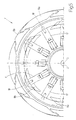
Figure 5 ,segments 9 are not all alike, but divided into two alternating types, i.e.outer segments 9a alternating withinner segments 9b. Eachouter segment 9a has a trapezoidal section with a circular outer major base, so that a recess is formed, between each two adjacentouter segments 9a, in which to fit aninner segment 9b, which has a trapezoidal section with an outer minor base. - When
segments 9 are in the contracted position, the outer surface ofcentral sections 7 is defined solely by the union of the outer surfaces ofouter segments 9a; conversely, whensegments 9 expand, the gap formed between each two adjacentouter segments 9a is filled by an underlyinginner segment 9b, so that, even in the expanded configuration,central sections 7 have a sufficiently even outer surface (i.e. with no major breaks) to effectively support the component parts of the tyre being formed. - As shown clearly in
Figure 5 , ascentral sections 7 expand/contract,inner segments 9b travel further thanouter segments 9a (roughly 10-12 mm further), which is achieved by a difference in the shape and/or size of transmission levers 20, and in the axial position of the pivots of transmission levers 20 contactingcorresponding pistons 17. In other words,pneumatic actuating device 19 is the same for all of segments 9 (i.e. produces the same travel for all of segments 9), and the difference in travel betweeninner segments 9b andouter segments 9a is achieved solely by a different transmission ratio produced by the difference intransmission levers 20. Because transmission levers 20 ofinner segments 9b are larger thantransmission levers 20 ofouter segments 9a, thecylindrical seats 16 associated withinner segments 9b are offset roughly 10 mm axially (i.e. parallel to axis of rotation 3) with respect tocylindrical seats 16 associated withouter segments 9a, so as to accommodate thelarger transmission levers 20 ofinner segments 9b. - Formation of a tyre on building
drum 1 will now be described with reference toFigures 6-10 . - To begin with, the various parts of the tyre - first the
sidewalls 35 and then thecarcass 36 and beads 37 - are placed about building drum 1 (Figure 6 ). -
Bead locking devices 6 are then activated to lock beads 37 (Figure 7 ). - At this point, pre-forming is performed by inflating
former bladder 12, bringingcentral sections 7 closer together axially, i.e. reducing the overall width of central sections 7 (Figure 8 ), and expandingcentral sections 7 radially to adequately supportsidewalls 35. - Next, turn-up is performed by inflating
inflatable bags 26 of lateral sections 5 (Figure 9 ). - And finally, stitching is performed by bringing
central sections 7 closer together axially, i.e. further reducing the overall width of central sections 7 (Figure 10 ).
Claims (20)
- A tyre building drum (1) comprising :a central shaft (2) mounted for rotation about a longitudinal axis (3) of rotation;two lateral sections (5), each having a bead locking device (6);two central sections (7) movable radially to expand or contract; anda toroidal flexible former bladder (12) covering the central sections (7);the building drum (1) being characterized in that the lateral sections (5) are mounted to slide axially with respect to the central sections (7) between a work position, in which the lateral sections (5) contact the central sections (7), and a maintenance position, in which the lateral sections (5) are detached from the central sections (7).
- A building drum (1) as claimed in Claim 1, wherein each central section (7) comprises a first pneumatic actuating device (19), in turn comprising an annular first actuating body (21); and each lateral section (5) is mounted to slide on the first actuating body (21) of the first pneumatic actuating device (19).
- A building drum (1) as claimed in Claim 1 or 2, wherein each central section (7) comprises an annular first supporting body (8) supporting a number of first segments (9), which are equally spaced about the first supporting body (8) and movable radially with respect to the first supporting body (8).
- A building drum (1) as claimed in Claim 3, wherein each first segment (9) has a number of fingers (10) spaced a given distance apart to define, between each two adjacent fingers (10), a recess (11) of at least the same width as a finger (10); the fingers (10) of the first segments (9) of one central section (7) being aligned with and facing the recesses (11) of the first segments (9) of the other central section (7), so that each finger (10) slides freely inside a respective recess (11) between two fingers (10) of the other central section (7); and the fingers (10) of the first segments (9) interlace when the two central sections (7) are brought together.
- A building drum (1) as claimed in Claim 3 or 4, wherein the former bladder (12) is fixed laterally to each first supporting body (8) by means of a fastening ring (13) screwed to an outer lateral wall (14) of the first supporting body (8) by means of screws (15).
- A building drum (1) as claimed in Claim 3, 4 or 5, wherein each annular first supporting body (8) has a number of radial first cylindrical seats (16), each housing in sliding manner a first piston (17) supporting a first segment (9); and each first piston (17) is connected mechanically to the first pneumatic actuating device (19) by a curved transmission lever (20), so as to move radially along the first cylindrical seat (16).
- A building drum (1) as claimed in Claim 6, wherein each first segment (9) is screwed to the first piston (17) by a pair of radial screws (18).
- A building drum (1) as claimed in Claim 6 or 7, wherein two annular first chambers (22a, 22b) are defined inside the first actuating body (21) of the first pneumatic actuating device (19), and in which respective second pistons (23a, 23b), integral with each other, slide axially; and each curved transmission lever (20) is hinged at one end to a second piston (23b), and at the other end to the first piston (17).
- A building drum (1) as claimed in Claim 3, 4 or 5, wherein the first segments (9) are divided into two types arranged alternately and comprising first outer segments (9a) alternating with first inner segments (9b); when the first segments (9) are in the contracted position, the outer surface of the central sections (7) is defined solely by the union of the outer surfaces of the first outer segments (9a); and, when the first segments (9) are expanded, the gap formed between each two adjacent first outer segments (9a) is filled by an underlying first inner segment (9b).
- A building drum (1) as claimed in Claim 9, wherein each first outer segment (9a) is trapezoidal in section, with a circular outer major base; and, between each two adjacent first outer segments (9a), a recess is formed, in which is inserted a first inner segment (9b), which is trapezoidal in section with an outer minor base.
- A building drum (1) as claimed in Claim 9 or 10, wherein the first inner segments (9b) travel further than the first outer segments (9a) as the central sections (7) expand/contract.
- A building drum (1) as claimed in Claim 11, wherein:each annular first supporting body (8) has a number of radial first cylindrical seats (16), each housing in sliding manner a first piston (17) supporting a first segment (9);each first piston (17) is connected mechanically to the first pneumatic actuating device (19) by a curved transmission lever (20), so as to move radially along the first cylindrical seat (16);the first pneumatic actuating device (19) is common to all the first segments (9); andthe difference in travel of the first inner segments (9b) and first outer segments (9a) is achieved solely by a different transmission ratio produced by differences in the transmission levers (20) transmitting motion from the first pneumatic actuating device (19) to the first segments (9).
- A building drum (1) as claimed in one of Claims 2 to 12, wherein each lateral section (5) comprises an annular second supporting body (24) mounted to slide axially on the first pneumatic actuating device (19).
- A building drum (1) as claimed in Claim 13, wherein, in the work position, the annular second supporting body (24) is locked to the first pneumatic actuating device (19) by at least one radial lock screw (25).
- A building drum (1) as claimed in Claim 13 or 14, wherein each annular second supporting body (24) supports an inflatable annular bag (26), which is connectable to a compressed-air source for inflation, or to a vacuum source for deflation.
- A building drum (1) as claimed in Claim 13, 14 or 15, wherein, on the side facing the central section (7), each second supporting body (24) has a number of radial second cylindrical seats (27), each housing in sliding manner a third piston (28) supporting a second segment (29); all the second segments (29) together define the bead locking device (6); and each third piston (28) is moved radially along the radial second cylindrical seat (27) by a second pneumatic actuating device (30) connected mechanically to the third piston (28) by a connecting wedge (31).
- A building drum (1) as claimed in Claim 16, wherein the second pneumatic actuating device (30) comprises an annular second chamber (32) formed in the second supporting body (24); and a fourth piston (33), integral with the connecting wedge (31), slides axially along the annular second chamber (32).
- A building drum (1) as claimed in Claim 17, wherein the bottom portion of each third piston (28) is fitted with an idle roller (34) which rolls along the inclined surface of the connecting wedge (31).
- A building drum (1) as claimed in one of Claims 1 to 18, wherein the building drum (1) comprises two identical half-drums (4) movable axially to and from each other; and each half-drum (4) comprises a lateral section (5) and a central section (7).
- A building drum (1) as claimed in Claim 19, wherein each half-drum (4) is mounted on a slide, and is slid axially with respect to the central shaft (2) by a pneumatic actuator.
Priority Applications (1)
| Application Number | Priority Date | Filing Date | Title |
|---|---|---|---|
| PL08153853T PL2008798T3 (en) | 2007-06-27 | 2008-03-31 | Tyre building drum |
Applications Claiming Priority (1)
| Application Number | Priority Date | Filing Date | Title |
|---|---|---|---|
| IT000465A ITTO20070465A1 (en) | 2007-06-27 | 2007-06-27 | TIRE DRYING DRUM |
Publications (2)
| Publication Number | Publication Date |
|---|---|
| EP2008798A1 EP2008798A1 (en) | 2008-12-31 |
| EP2008798B1 true EP2008798B1 (en) | 2012-06-06 |
Family
ID=39768787
Family Applications (1)
| Application Number | Title | Priority Date | Filing Date |
|---|---|---|---|
| EP08153853A Not-in-force EP2008798B1 (en) | 2007-06-27 | 2008-03-31 | Tyre building drum |
Country Status (5)
| Country | Link |
|---|---|
| EP (1) | EP2008798B1 (en) |
| ES (1) | ES2387515T3 (en) |
| IT (1) | ITTO20070465A1 (en) |
| PL (1) | PL2008798T3 (en) |
| ZA (1) | ZA200803132B (en) |
Cited By (1)
| Publication number | Priority date | Publication date | Assignee | Title |
|---|---|---|---|---|
| US10259181B2 (en) | 2012-08-15 | 2019-04-16 | The Goodyear Tire & Rubber Company | Sleeveless tire building drum |
Families Citing this family (7)
| Publication number | Priority date | Publication date | Assignee | Title |
|---|---|---|---|---|
| ITTO20100323A1 (en) | 2010-04-20 | 2011-10-21 | Bridgestone Corp | METHOD OF CONSTRUCTION OF A TIRE WITH A SINGLE FORMING DRUM |
| CN103085301A (en) * | 2011-10-27 | 2013-05-08 | 软控股份有限公司 | Tire building machine belt layer drum and radial expansion and contraction method thereof |
| KR102263087B1 (en) * | 2017-10-30 | 2021-06-10 | 세이프-런 머시너리(쑤저우) 컴퍼니 리미티드 | Forming drum, tire forming machine and tire forming method of tire forming machine |
| CN107584786A (en) * | 2017-10-30 | 2018-01-16 | 萨驰华辰机械(苏州)有限公司 | Assembly drum and tyre building machine |
| EP3917765B1 (en) * | 2019-01-28 | 2024-03-27 | Davian Enterprises, LLC | Expandable belt and tread drum with reverse offset fingers |
| CN111002611B (en) * | 2019-12-26 | 2025-03-07 | 山东宏盛橡胶科技有限公司 | A run-flat forming drum |
| CN114683599B (en) * | 2020-12-31 | 2025-07-04 | 软控股份有限公司 | Method and device for adjusting specifications of forming drum |
Family Cites Families (4)
| Publication number | Priority date | Publication date | Assignee | Title |
|---|---|---|---|---|
| US4214939A (en) | 1978-03-15 | 1980-07-29 | Nrm Corporation | Tire building machine |
| JPH07100954A (en) | 1993-10-06 | 1995-04-18 | Bridgestone Corp | Aligning method for green case |
| AU2003303564A1 (en) | 2002-12-30 | 2004-07-29 | Michelin Recherche Et Technique S.A. | Tire building apparatus and assembly process |
| ATE400425T1 (en) | 2004-09-20 | 2008-07-15 | Pirelli | METHOD AND DEVICE FOR PRODUCING TIRES |
-
2007
- 2007-06-27 IT IT000465A patent/ITTO20070465A1/en unknown
-
2008
- 2008-03-31 PL PL08153853T patent/PL2008798T3/en unknown
- 2008-03-31 ES ES08153853T patent/ES2387515T3/en active Active
- 2008-03-31 EP EP08153853A patent/EP2008798B1/en not_active Not-in-force
- 2008-04-09 ZA ZA200803132A patent/ZA200803132B/en unknown
Cited By (1)
| Publication number | Priority date | Publication date | Assignee | Title |
|---|---|---|---|---|
| US10259181B2 (en) | 2012-08-15 | 2019-04-16 | The Goodyear Tire & Rubber Company | Sleeveless tire building drum |
Also Published As
| Publication number | Publication date |
|---|---|
| PL2008798T3 (en) | 2012-10-31 |
| ZA200803132B (en) | 2009-02-25 |
| ITTO20070465A1 (en) | 2008-12-28 |
| ES2387515T3 (en) | 2012-09-25 |
| EP2008798A1 (en) | 2008-12-31 |
Similar Documents
| Publication | Publication Date | Title |
|---|---|---|
| EP2008798A1 (en) | Tyre building drum | |
| EP2111334B1 (en) | Process and apparatus for building tyres | |
| US20150158261A1 (en) | Process and apparatus for assembling tyres | |
| CN103429420B (en) | For manufacturing the method and apparatus for tyre for vehicle wheel, pneumatic | |
| EP2698243B1 (en) | Sleeveless tire building drum | |
| EP2698244B1 (en) | Sleeveless tire building drum with interchangeable width elements | |
| CN105451978B (en) | Process and apparatus for constructing tires for vehicle wheels and tires for vehicle wheels | |
| JP6425944B2 (en) | Tire assembly drum | |
| NL2014555B1 (en) | Method and drum for manufacturing a tyre, in particular a run-flat tyre. | |
| US20080264570A1 (en) | Tyre Drum Assembly Including Turn-Up Mechanism for Building an Unvulcanized Tyre | |
| JP4447820B2 (en) | Tire shaping molding drum and molding method | |
| JPH07266455A (en) | Tire assembling drum | |
| JP5281671B2 (en) | Shaping former for run-flat tires | |
| EP1601521A1 (en) | A method and an apparatus for manufacturing tyres for vehicle wheels | |
| WO2016060560A1 (en) | Method and drum for manufacturing a tyre, in particular a run-flat tyre | |
| US20100032079A1 (en) | Process and apparatus for manufacturing tyres | |
| EP0692368B1 (en) | Tire-forming drum and method of manufacturing a green tire | |
| JP2006168367A (en) | Bead fixing segment interlaced for tire manufacturing drum | |
| GB2031815A (en) | Tyre building drums | |
| EP1556208B1 (en) | Method and apparatus for manufacturing a pneumatic tyre for vehicle wheels | |
| EP1551619A4 (en) | METHOD AND APPARATUS FOR MANUFACTURING TIRES | |
| WO1992007708A1 (en) | Green tire building apparatus | |
| WO2004037523A1 (en) | Method and apparatus for manufacturing a pneumatic tyre for vehicle wheels | |
| WO2001036186A1 (en) | Process and apparatus for tire manufacturing with optimized bead positioning |
Legal Events
| Date | Code | Title | Description |
|---|---|---|---|
| PUAI | Public reference made under article 153(3) epc to a published international application that has entered the european phase |
Free format text: ORIGINAL CODE: 0009012 |
|
| AK | Designated contracting states |
Kind code of ref document: A1 Designated state(s): AT BE BG CH CY CZ DE DK EE ES FI FR GB GR HR HU IE IS IT LI LT LU LV MC MT NL NO PL PT RO SE SI SK TR |
|
| AX | Request for extension of the european patent |
Extension state: AL BA MK RS |
|
| 17P | Request for examination filed |
Effective date: 20090629 |
|
| 17Q | First examination report despatched |
Effective date: 20090722 |
|
| AKX | Designation fees paid |
Designated state(s): DE ES FR GB PL |
|
| GRAP | Despatch of communication of intention to grant a patent |
Free format text: ORIGINAL CODE: EPIDOSNIGR1 |
|
| GRAS | Grant fee paid |
Free format text: ORIGINAL CODE: EPIDOSNIGR3 |
|
| GRAA | (expected) grant |
Free format text: ORIGINAL CODE: 0009210 |
|
| AK | Designated contracting states |
Kind code of ref document: B1 Designated state(s): DE ES FR GB PL |
|
| REG | Reference to a national code |
Ref country code: GB Ref legal event code: FG4D |
|
| REG | Reference to a national code |
Ref country code: DE Ref legal event code: R096 Ref document number: 602008016131 Country of ref document: DE Effective date: 20120809 |
|
| REG | Reference to a national code |
Ref country code: ES Ref legal event code: FG2A Ref document number: 2387515 Country of ref document: ES Kind code of ref document: T3 Effective date: 20120925 |
|
| REG | Reference to a national code |
Ref country code: PL Ref legal event code: T3 |
|
| PLBE | No opposition filed within time limit |
Free format text: ORIGINAL CODE: 0009261 |
|
| STAA | Information on the status of an ep patent application or granted ep patent |
Free format text: STATUS: NO OPPOSITION FILED WITHIN TIME LIMIT |
|
| 26N | No opposition filed |
Effective date: 20130307 |
|
| REG | Reference to a national code |
Ref country code: DE Ref legal event code: R097 Ref document number: 602008016131 Country of ref document: DE Effective date: 20130307 |
|
| REG | Reference to a national code |
Ref country code: FR Ref legal event code: CA Effective date: 20140812 |
|
| REG | Reference to a national code |
Ref country code: FR Ref legal event code: PLFP Year of fee payment: 9 |
|
| REG | Reference to a national code |
Ref country code: FR Ref legal event code: PLFP Year of fee payment: 10 |
|
| REG | Reference to a national code |
Ref country code: FR Ref legal event code: PLFP Year of fee payment: 11 |
|
| PGFP | Annual fee paid to national office [announced via postgrant information from national office to epo] |
Ref country code: GB Payment date: 20190320 Year of fee payment: 12 Ref country code: DE Payment date: 20190321 Year of fee payment: 12 Ref country code: FR Payment date: 20190322 Year of fee payment: 12 Ref country code: PL Payment date: 20190328 Year of fee payment: 12 |
|
| PGFP | Annual fee paid to national office [announced via postgrant information from national office to epo] |
Ref country code: ES Payment date: 20190418 Year of fee payment: 12 |
|
| REG | Reference to a national code |
Ref country code: DE Ref legal event code: R119 Ref document number: 602008016131 Country of ref document: DE |
|
| PG25 | Lapsed in a contracting state [announced via postgrant information from national office to epo] |
Ref country code: FR Free format text: LAPSE BECAUSE OF NON-PAYMENT OF DUE FEES Effective date: 20200331 Ref country code: DE Free format text: LAPSE BECAUSE OF NON-PAYMENT OF DUE FEES Effective date: 20201001 |
|
| GBPC | Gb: european patent ceased through non-payment of renewal fee |
Effective date: 20200331 |
|
| PG25 | Lapsed in a contracting state [announced via postgrant information from national office to epo] |
Ref country code: GB Free format text: LAPSE BECAUSE OF NON-PAYMENT OF DUE FEES Effective date: 20200331 |
|
| REG | Reference to a national code |
Ref country code: ES Ref legal event code: FD2A Effective date: 20210812 |
|
| PG25 | Lapsed in a contracting state [announced via postgrant information from national office to epo] |
Ref country code: ES Free format text: LAPSE BECAUSE OF NON-PAYMENT OF DUE FEES Effective date: 20200401 |
|
| PG25 | Lapsed in a contracting state [announced via postgrant information from national office to epo] |
Ref country code: PL Free format text: LAPSE BECAUSE OF NON-PAYMENT OF DUE FEES Effective date: 20200331 |