EP2008496B1 - Loudspeaker device - Google Patents
Loudspeaker device Download PDFInfo
- Publication number
- EP2008496B1 EP2008496B1 EP07748038A EP07748038A EP2008496B1 EP 2008496 B1 EP2008496 B1 EP 2008496B1 EP 07748038 A EP07748038 A EP 07748038A EP 07748038 A EP07748038 A EP 07748038A EP 2008496 B1 EP2008496 B1 EP 2008496B1
- Authority
- EP
- European Patent Office
- Prior art keywords
- loudspeaker
- elements
- centre
- signal
- less
- Prior art date
- Legal status (The legal status is an assumption and is not a legal conclusion. Google has not performed a legal analysis and makes no representation as to the accuracy of the status listed.)
- Active
Links
- 238000004519 manufacturing process Methods 0.000 claims description 2
- 230000000694 effects Effects 0.000 description 22
- 230000008901 benefit Effects 0.000 description 8
- 238000000034 method Methods 0.000 description 7
- 230000010363 phase shift Effects 0.000 description 3
- 210000005069 ears Anatomy 0.000 description 2
- 238000001914 filtration Methods 0.000 description 2
- 230000002411 adverse Effects 0.000 description 1
- 230000004075 alteration Effects 0.000 description 1
- 230000007423 decrease Effects 0.000 description 1
- 230000000593 degrading effect Effects 0.000 description 1
- 238000010586 diagram Methods 0.000 description 1
- 238000002955 isolation Methods 0.000 description 1
- 238000012986 modification Methods 0.000 description 1
- 230000004048 modification Effects 0.000 description 1
- 238000000926 separation method Methods 0.000 description 1
- 230000005236 sound signal Effects 0.000 description 1
Images
Classifications
-
- H—ELECTRICITY
- H04—ELECTRIC COMMUNICATION TECHNIQUE
- H04R—LOUDSPEAKERS, MICROPHONES, GRAMOPHONE PICK-UPS OR LIKE ACOUSTIC ELECTROMECHANICAL TRANSDUCERS; DEAF-AID SETS; PUBLIC ADDRESS SYSTEMS
- H04R5/00—Stereophonic arrangements
- H04R5/02—Spatial or constructional arrangements of loudspeakers
-
- H—ELECTRICITY
- H04—ELECTRIC COMMUNICATION TECHNIQUE
- H04R—LOUDSPEAKERS, MICROPHONES, GRAMOPHONE PICK-UPS OR LIKE ACOUSTIC ELECTROMECHANICAL TRANSDUCERS; DEAF-AID SETS; PUBLIC ADDRESS SYSTEMS
- H04R1/00—Details of transducers, loudspeakers or microphones
- H04R1/20—Arrangements for obtaining desired frequency or directional characteristics
- H04R1/32—Arrangements for obtaining desired frequency or directional characteristics for obtaining desired directional characteristic only
- H04R1/40—Arrangements for obtaining desired frequency or directional characteristics for obtaining desired directional characteristic only by combining a number of identical transducers
- H04R1/403—Arrangements for obtaining desired frequency or directional characteristics for obtaining desired directional characteristic only by combining a number of identical transducers loud-speakers
-
- H—ELECTRICITY
- H04—ELECTRIC COMMUNICATION TECHNIQUE
- H04S—STEREOPHONIC SYSTEMS
- H04S1/00—Two-channel systems
- H04S1/002—Non-adaptive circuits, e.g. manually adjustable or static, for enhancing the sound image or the spatial distribution
-
- H—ELECTRICITY
- H04—ELECTRIC COMMUNICATION TECHNIQUE
- H04R—LOUDSPEAKERS, MICROPHONES, GRAMOPHONE PICK-UPS OR LIKE ACOUSTIC ELECTROMECHANICAL TRANSDUCERS; DEAF-AID SETS; PUBLIC ADDRESS SYSTEMS
- H04R2205/00—Details of stereophonic arrangements covered by H04R5/00 but not provided for in any of its subgroups
- H04R2205/022—Plurality of transducers corresponding to a plurality of sound channels in each earpiece of headphones or in a single enclosure
-
- H—ELECTRICITY
- H04—ELECTRIC COMMUNICATION TECHNIQUE
- H04S—STEREOPHONIC SYSTEMS
- H04S1/00—Two-channel systems
Definitions
- the present invention relates to loudspeaker devices for reproduction of audio stereo signals.
- the present invention relates to a loudspeaker device according to the preamble of claim 1.
- the present invention also relates to an audio stereo reproduction system according to claim 19.
- loudspeaker systems that introduce so called crosstalk cancellation by means of DSP, see, for example, US3236949 and US5862227 .
- the purpose of such systems is to eliminate the signal that is reaching the left ear from the right speaker and vice versa. This is in order to create a binaural loudspeaker system.
- the disadvantage of such a system is that the complexity of the cross talk cancellation signal itself is degrading the sound quality.
- All other ways than the binaural method to record and reproduce sound, such as the above conventional two speaker set-up, is a creation of an imaginary sound image that is truly subjective and need not have even a remote resemblance with the actual experience at the recording position.
- US 3 892 624 A discloses a stereophonic sound reproducing system having left and right loudspeaker elements that can be housed in one common box.
- the loudspeaker elements (transducers) are arranged in a single speaker box in the same resonator volume.
- the loudspeaker device comprises first and second loudspeaker elements, which are located in close proximity to each other, wherein said first and second loudspeaker elements are arranged to radiate sound in a first direction of propagation, wherein said first and second loudspeaker elements are acoustically isolated and arranged to receive a first signal and a second signal, respectively, at least part of said first signal being in anti-phase relative to said second signal, wherein said device further includes third and fourth loudspeaker elements, arranged to propagate sound in said first direction.
- Said third loudspeaker element is located in close proximity to said first loudspeaker element and is arranged to receive at least part of said first signal.
- Said fourth loudspeaker element being located in close proximity to said second loudspeaker element and arranged to receive at least part of said second signal.
- the centre of said third loudspeaker element is located such that a first axis, intersecting the centre of said first loudspeaker element and the centre of said third loudspeaker element, is inclined an angle ⁇ relative to a horizontal plane.
- the centre of said fourth loudspeaker element is located such that a second axis, intersecting the centre of said second loudspeaker element and the centre of said fourth loudspeaker element, is inclined at an angle ⁇ relative to a horizontal plane, ⁇ being 0° - ⁇ 30°.
- said third and fourth elements are arranged such that said first and second axis have equal absolute values of ⁇ and intersect at a point substantially on a vertical axis passing between said first and second elements.
- the signals to the said third and fourth elements are low-pass filtered, the cut-off frequency of said low-pass filters being less than 2.5 kHz.
- a distance D between the centre of said first element and the centre of said third element, and between the centre of said second element and the centre of said fourth element should be less than or equal to twice the diameters d of said first and second elements in order to fully benefit from the advantages of the present invention.
- loudspeaker elements are arranged in close proximity to said first and second elements, and/or said third and fourth elements. This has the advantage that the perceived stereo effect for certain frequencies may be improved even further.
- Said first and second loudspeaker elements constitute a pair of identical loudspeaker elements, and may be located within less than one quarter of the shortest wavelength emitted by the elements, or, if the shortest wavelength emitted by the elements is less than 68 cm, less than 17 cm.
- said first signal are equivalent to the sum of a mid input signal (M) and a side input signal (S)
- said second signals are equivalent to the sum of a mid input signal (M) and a side signal (S) phase shifted 180°.
- At least part of the side input signal (S) or the mid input signal (M) may be phase shifted approximately 45°-135° prior to or at the production of the first and second signals.
- Said device may be an integrated part in an apparatus constituting any from the group: Studio Monitor, HiFi system, Home Cinema system, Compact Hifi system, Personal Radio system, TV Set, Laptop, PC Monitor, Personal Computer, Multimedia Speaker, Mobile Phone, PDA.
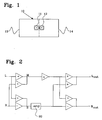
- Fig. 1 shows a prior art loudspeaker device 10.
- the loudspeaker device 10 comprises a first side 13 and a second side 14.
- the first side 13 comprises a first loudspeaker element 11, and the second side 14 comprises a second loudspeaker element 12.
- the disclosed device 10 is intended for stereo reproduction of an input stereo signal, and although the loudspeaker device 10 consists of a common enclosure, the resonator volumes, or cavities, of the loudspeaker elements 11 and 12 are acoustically isolated from each other.
- the term acoustical isolation does, in the present description and claims, here imply that no, or little, sound is transferred from one resonator volume to the other.
- the disclosed loudspeaker device may, e.g., be utilised for reproduction of sound according to a method as disclosed in fig. 2 , wherein a conventional input audio stereo signal comprises a left input stereo signal L and a right input stereo signal R.
- the L and R signals are used to obtain a mid signal M, and a side signal S, corresponding to the sum of the left L and right R input stereo signals, and the difference between the left L and right R input stereo signals, respectively.
- the output stereo signal L OUT is to be sent to a left side sound reproducing unit, in this case the loudspeaker element 11 of the first side 13, and constitutes the sum of the side signal, S, and the mid signal M multiplied by an attenuating factor ⁇ , e.g., in the range - 3 dB to -15 dB, while the output stereo signal R OUT , which is to be sent to a right side sound reproducing unit (in this case, the loudspeaker element 12 of the right hand side 14) is the sum of the inverted side signal, S, and the mid signal M multiplied by an attenuating factor ⁇ .
- ⁇ e.g., in the range - 3 dB to -15 dB
- the side signal S may, as is disclosed in the figure, be phase shifted -90° prior to the creation of the output stereo signals L OUT , and R OUT , using phase shifting means 20.
- phase shifting means 20 This method is described in detail in the international patent application W02005/009078 .
- the phase shift may be any phase shift in an interval between 45°-135°, and, optionally, it may be performed on the mid signal M instead.
- the closely located loudspeaker elements 11 and 12 should, for optimum performance, be located such that a minimal coloration caused by lobing in the resultant emitted sound pattern due to interference between the loudspeaker elements is obtained. This is achieved when the distance between the loudspeaker elements is smaller than one quarter of the wavelength of the sound being emitted. Achieving this implies that higher frequency loudspeaker elements should be put closer to each other than lower frequency loudspeaker elements.
- the distance between the centres of the elements should be less than one quarter of the shortest wavelength emitted by the elements, or, if the shortest wavelength emitted by the elements is less than 68 cm (i.e., frequencies > 500 Hz), at least no longer than 17 cm, preferably closer.
- Arranging the elements 11, 12 in this way has as result that the elements will act as a dipole.
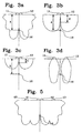
- the lobe pattern for frequencies wherein ⁇ (wavelength) is short relative to the diameter of the speaker element, i.e. high frequencies, when the elements are functioning as a dipole is shown in fig. 3a .
- the elements 11 and 12 act as a dipole up to a distance A from the loudspeaker elements before the lobe pattern separates and the dipole effect is lost to the ears of the listener.
- the elements 11, 12 are acting as a dipole, they consume energy from each other, i.e., there are signal cancellations, or partial cancellations, in areas where the signals overlap, said cancellations resulting in a perceived stereo effect at the location of a listener 16.
- the lobe pattern from the same set of loudspeaker elements 11, 12 will exhibit the lobe pattern of fig. 3b .
- the elements 11 and 12 still acts as a dipole, but now the lobe pattern separates at a distance B ⁇ A from the loudspeaker elements, wherein the dipole effect is lost at positions beyond B. Consequently, the listener of fig. 3a , at a distance A from the loudspeaker device 10, will not experience a satisfactory stereo effect in regard to these lower frequencies, and it is quite possible that the distance B will be considered as far too short even in an ordinary living room.
- the relevant frequency interval is the frequency interval ranging from the resonance frequency f 0 of the loudspeaker elements up to about 1,5 - 2,5 kHz, above which the situation in fig. 3a usually prevails. If the situation in fig. 3a corresponds to 1,5 kHz, and the situation in fig. 3b corresponds to 750 Hz, the situation may be as bad as in fig. 3c , wherein the dipole effect separates at a distance C, C ⁇ B ⁇ A, when it comes to frequencies around 2-300 Hz.
- a loudspeaker device according to an exemplary embodiment of the present invention.
- the loudspeaker device is similar to the device in fig. 1 , however now provided with two additional elements 46, 47, in this example similar to the elements 41, 42.
- the frequency range of the elements 46, 47 at least partially overlap the frequency range of the elements 41, 42, and may be identical to the frequency range of the elements 41, 42, in which case the elements are fed by the same frequency range of the output signal.
- the elements 46, 47 are added in order to improve the stereo reproduction for lower frequencies, and do so by adding loudspeaker element surface.
- the increase in element surface playing a specific frequency has as result that the maximum wavelengths for which the dipole effect is achieved at position A increases, i.e., the desired function is obtained for lower frequencies since A ⁇ d element will be valid for longer wavelengths.
- the addition of the element 46 (47), having an equal surface as the element 41 (42) is equal to having a single element 41' (42') (not shown) having a diameter 2 * d 41 , i.e., about 41% greater than the diameter of element 41 (42). Consequently, the present invention provides the same effect as a loudspeaker element of considerable larger diameter. Accordingly, the advantage of using a configuration according to the present invention is that it improves stereo reproduction in applications wherein element dimensions, especially element height, is restricted.
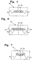
- the extra elements 46, 47 has, as is shown in fig. 5 , the disadvantage that these elements will contribute to the total lobe pattern of the device 40 by individual additional lobes. This means that these lobe patterns will interfere with the lobe pattern of elements 41, 42, and may thereby reduce the quality of high frequency reproduction while improving low frequency reproduction. Therefore, the signals to the elements 46, 47 are low-pass filtered. This means that while the elements 41, 42 reproduces the input signal full range, i.e., throughout the capability of the element or the portion of the frequency range apportioned to said element, the elements 46, 47 will only reproduce the same signal up to a certain frequency.
- the signals to the elements 46, 47 are preferably low-pass filtered such that the cut-off frequency of said loudspeaker elements is less than or equal to 2.5 kHz or c /3 D , wherein c is the speed of sound in the medium, e.g., ⁇ 340m/s in room tempered air. Consequently, the lobe pattern of the elements 41, 42 will be substantially undisturbed for frequencies above the cut-off frequency of the low-pass filter.
- the cut-off frequency is set to ⁇ 1,5 kHz.
- the disclosed embodiment has the advantage that the distances B and/or C are increased with a maintained possibility of implementing the present invention where there are space requirements, and thereby enable a listener to increase the distance to the loudspeaker device 40 while still maintaining a satisfactory stereo reproduction for a wider frequency range and without substantially disturbing the stereo reproduction for higher frequencies.
- loudspeaker elements may be added. This is disclosed in fig. 6 , wherein, in comparison to fig. 1 , four additional elements 66-69 are provided, two to each side. This has the advantage that the effective loudspeaker element area is increased further.
- the signals feeding these should preferably be low-pass filtered as above.
- the signal to the elements 68, 69 should be low-pass filtered, wherein the corresponding equation c /3 D x applies, wherein D x is defined as the distance between the centres of the centremost element (61 or 62) and a particular element x, e.g., element 68.
- the elements have been described as being located along a horizontal axis. It is, however, if the application so permits, possible to arrange the additional elements with an angle relative to the centremost element. For example, only the centremost element may be subject to space restrictions, while the outer elements may be positioned more freely.
- One such example is shown in fig. 7 , wherein the elements 76, 77 are arranged at an inclined angle relative to the elements 71, 72.
- the centre of the element 76 is located such that a first axis intersecting the centre of the element 71 and the centre of the element 76 is inclined an angle ⁇ , wherein ⁇ is 0° - ⁇ 30° relative to a horizontal plane.
- the centre of the element 77 is located such that a second axis intersecting the centre of the element 72 and the centre of the element 77 is inclined at an angle ⁇ relative to a horizontal plane, ⁇ being 0° - ⁇ 30°.
- the inclination angle should not be more than ⁇ 30 degrees in order to prevent disturbance of vertical lobe pattern.
- the elements 76, 77 should be arranged such that said first and second axis have equal absolute values of ⁇ and intersect at a point substantially on a vertical axis passing between the elements 71, 72.
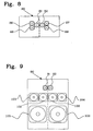
- FIG. 8 is shown another exemplary embodiment wherein two additional elements 86, 88 and 87, 89, respectively, are arranged at inclined angles relative to the centremost elements 81, 82.
- the present invention has been disclosed as a single set of elements.
- fig. 9 is shown an alternative embodiment, wherein different sets of elements reproduce signals having different frequency ranges.
- the disclosed device comprises a first set of elements 91-92, which are used for high-frequency reproduction, i.e., reproduce the uppermost of the frequency range of the device, that is, a high-pass filtered portion of the frequency range e.g., frequencies above 2.5 kHz.
- the set of elements 101-104 functions as above and reproduces frequencies of a frequency there below. Since mid-range elements by nature have a larger diameter, a low-pass filter cut-off frequency of no more than c/3D will ensure proper function.
- this embodiment has the advantage that an even larger element surface may be obtained for lower frequencies, since the high-frequency range is handled by a separate set of loudspeaker elements. Further, as stated above, lower frequency loudspeaker elements may be arranged more spaced apart without loosing the dipole effect.
- the disclosed device further comprises loudspeaker elements 105-106, which are used for reproduction of the lowest frequency range, e.g., frequencies below 200 Hz.
- loudspeaker elements 105-106 which are used for reproduction of the lowest frequency range, e.g., frequencies below 200 Hz.
- additional elements according to the present invention could be used for the elements 105, 106 as well.
- the present invention has been disclosed in connection with a "conventional" loudspeaker device intended as a substitute to a conventional two-speaker stereo system.
- the present invention is applicable everywhere wherein closely located loudspeaker elements may be used to reproduce stereo sound.
- Such devices include, but are not restricted to, Studio Monitors, HiFi Speakers, Home Cinema, Compact Hifi, Personal Radios, Car Stereo System, TV-Sets, Laptops, PC Monitors, Multimedia Speakers, Mobile Phones.
- two full range loudspeaker elements may be utilised to reproduce stereo sound.
- the available space is often very limited, and the loudspeaker elements are often subject to constraints regarding possible diameter, which, as disclosed above, has an adverse effect on the stereo reproduction of lower frequencies.
- many modern TV sets have similar problems as the loudspeaker elements often are arranged below the screen and therefore should have as small diameter as possible.
- Use of an additional set of speaker elements according to the present invention preferably using low-pass filtering of the signal to the outer elements, may substantially increase the stereo quality of mobile telephones and TV sets.
- the loudspeaker device has been disclosed as an integral unit. Alternatively, it could consist of two separate units, placed in immediate vicinity of each other, or even being attached to each other.
Description
- The present invention relates to loudspeaker devices for reproduction of audio stereo signals. In particular, the present invention relates to a loudspeaker device according to the preamble of claim 1. The present invention also relates to an audio stereo reproduction system according to claim 19.
- Once, the expectations on reproduced audio sound were no greater than what monophonic reproduction could produce, and, accordingly, this satisfied most listeners. In course of time, however, the demand on high quality reproduction of stereo sound, e.g., recordings from a recording studio or recordings from a live concert, has been constantly increasing.
- Consequently, various systems have been developed, each being able to reproduce true stereo sound to a greater or lesser extent.
- The system that most readily comes to mind is a conventional system for stereophonic reproduction wherein left and right side speakers are disposed in front of a listener and with a certain distance separating the speakers. Most reproduction systems of today are based on this technology. However, true reproduction of the electrical stereo signal, both in terms of relative intensity between the sound waves perceived by the ears of the listener and the time difference between these, can at best be perceived only at one single position in relation to the loudspeakers, as these methods are often subject to incorrect translation of the electrical stereo information due to preferences of the separate loudspeakers and how the loudspeakers are positioned in relation to the listener.
- The system coming closest to virtually move the listener to the recording location, i.e. to convey an impression of the true location of the different sound sources of the original event, is the binaural method of recording and the binaural method of reproduction (headphones). There are, however, a number of loudspeaker systems that introduce so called crosstalk cancellation by means of DSP, see, for example,
US3236949 andUS5862227 . The purpose of such systems is to eliminate the signal that is reaching the left ear from the right speaker and vice versa. This is in order to create a binaural loudspeaker system. The disadvantage of such a system is that the complexity of the cross talk cancellation signal itself is degrading the sound quality. All other ways than the binaural method to record and reproduce sound, such as the above conventional two speaker set-up, is a creation of an imaginary sound image that is truly subjective and need not have even a remote resemblance with the actual experience at the recording position. - Consequently, there exists a need for a sound reproduction system that provides identical reproduction of the stereo sound image regardless of setup and quality of the loudspeakers. One such system that solves this problem is described in the patent application
WO01/39548 WO01/39548 - A problem with such a system with closely located loudspeaker units, however, is that as the distance between loudspeaker units and listener increases, the performance of the system as regarding the fidelity in perceived stereo effect at the listeners location degrades with increasing distance and in the extreme case vanishes totally. Consequently, there exists a need for an improved system for reproducing sound.
-
US 3 892 624 A discloses a stereophonic sound reproducing system having left and right loudspeaker elements that can be housed in one common box. The loudspeaker elements (transducers) are arranged in a single speaker box in the same resonator volume. - It is an object of the present invention to provide a loudspeaker device that solves the above mentioned problem. This object is achieved by a loudspeaker device as defined in the characterising portion of claim 1.
- According to the present invention, the loudspeaker device comprises first and second loudspeaker elements, which are located in close proximity to each other, wherein said first and second loudspeaker elements are arranged to radiate sound in a first direction of propagation, wherein said first and second loudspeaker elements are acoustically isolated and arranged to receive a first signal and a second signal, respectively, at least part of said first signal being in anti-phase relative to said second signal, wherein said device further includes third and fourth loudspeaker elements, arranged to propagate sound in said first direction. Said third loudspeaker element is located in close proximity to said first loudspeaker element and is arranged to receive at least part of said first signal. Said fourth loudspeaker element being located in close proximity to said second loudspeaker element and arranged to receive at least part of said second signal. The centre of said third loudspeaker element is located such that a first axis, intersecting the centre of said first loudspeaker element and the centre of said third loudspeaker element, is inclined an angle ϕ relative to a horizontal plane. The centre of said fourth loudspeaker element is located such that a second axis, intersecting the centre of said second loudspeaker element and the centre of said fourth loudspeaker element, is inclined at an angle ϕ relative to a horizontal plane, ϕ being 0° - ± 30°. Preferably said third and fourth elements are arranged such that said first and second axis have equal absolute values of ϕ and intersect at a point substantially on a vertical axis passing between said first and second elements. The signals to the said third and fourth elements are low-pass filtered, the cut-off frequency of said low-pass filters being less than 2.5 kHz.
- This has the advantage that a similar effect as of a loudspeaker element of considerable larger diameter is achieved, i.e., the elements will function as a dipole further out from the device, which has as result that the perceived stereo effect at a listener location some distance from the loudspeaker is substantially improved for frequencies, in particular in the range from f0 of the loudspeaker element to 2,5 kHz, wherein f0 is the resonance frequency of the loudspeaker element. The low-pass filtering of the signals to said third and fourth loudspeaker elements avoid alteration of the high frequency lobe pattern. Further, using a loudspeaker element configuration according to the present invention makes possible an improved stereo reproduction in applications wherein element dimensions, especially element height, is restricted.
- A distance D between the centre of said first element and the centre of said third element, and between the centre of said second element and the centre of said fourth element should be less than or equal to twice the diameters d of said first and second elements in order to fully benefit from the advantages of the present invention.
- Further loudspeaker elements are arranged in close proximity to said first and second elements, and/or said third and fourth elements. This has the advantage that the perceived stereo effect for certain frequencies may be improved even further.
- Said first and second loudspeaker elements constitute a pair of identical loudspeaker elements, and may be located within less than one quarter of the shortest wavelength emitted by the elements, or, if the shortest wavelength emitted by the elements is less than 68 cm, less than 17 cm.
- Further, said first signal are equivalent to the sum of a mid input signal (M) and a side input signal (S), and said second signals are equivalent to the sum of a mid input signal (M) and a side signal (S) phase shifted 180°.
- Further, at least part of the side input signal (S) or the mid input signal (M) may be phase shifted approximately 45°-135° prior to or at the production of the first and second signals.
- Said device may be an integrated part in an apparatus constituting any from the group: Studio Monitor, HiFi system, Home Cinema system, Compact Hifi system, Personal Radio system, TV Set, Laptop, PC Monitor, Personal Computer, Multimedia Speaker, Mobile Phone, PDA.
-
-
Fig. 1 discloses a prior art loudspeaker device; -
Fig. 2 is a block diagram illustrating a prior art system for processing stereo signals; -
Fig. 3a-c discloses lobe patterns for various frequencies radiated by thefig. 1 system; -
Fig. 3d discloses a lobe pattern for loudspeaker elements more spaced apart; -
Fig. 4 discloses a loudspeaker device according to an exemplary embodiment of the present invention; and -
Fig. 5 shows an example of a lobe pattern from two closely located loudspeaker elements acting as a bipole. -
Figs. 6-9 show alternative exemplary embodiments of the present invention. -
Fig. 1 shows a priorart loudspeaker device 10. Theloudspeaker device 10 comprises afirst side 13 and asecond side 14. Thefirst side 13 comprises afirst loudspeaker element 11, and thesecond side 14 comprises asecond loudspeaker element 12. The discloseddevice 10 is intended for stereo reproduction of an input stereo signal, and although theloudspeaker device 10 consists of a common enclosure, the resonator volumes, or cavities, of theloudspeaker elements - The disclosed loudspeaker device may, e.g., be utilised for reproduction of sound according to a method as disclosed in
fig. 2 , wherein a conventional input audio stereo signal comprises a left input stereo signal L and a right input stereo signal R. The L and R signals are used to obtain a mid signal M, and a side signal S, corresponding to the sum of the left L and right R input stereo signals, and the difference between the left L and right R input stereo signals, respectively. The output stereo signal LOUT, is to be sent to a left side sound reproducing unit, in this case theloudspeaker element 11 of thefirst side 13, and constitutes the sum of the side signal, S, and the mid signal M multiplied by an attenuating factor α, e.g., in the range - 3 dB to -15 dB, while the output stereo signal ROUT, which is to be sent to a right side sound reproducing unit (in this case, theloudspeaker element 12 of the right hand side 14) is the sum of the inverted side signal, S, and the mid signal M multiplied by an attenuating factor α. - This signal processing together with a loudspeaker device as disclosed in
fig. 1 allows an electrical audio stereo signal to be reproduced with a high degree of fidelity with high consistency in the perceived stereo image. In order to improve the degree of fidelity in perceived stereo effect at frequencies above 1-5 kHz, the side signal S may, as is disclosed in the figure, be phase shifted -90° prior to the creation of the output stereo signals LOUT, and ROUT, using phase shifting means 20. This method is described in detail in the international patent applicationW02005/009078 . Instead of a 90° phase shift, the phase shift may be any phase shift in an interval between 45°-135°, and, optionally, it may be performed on the mid signal M instead. - In the described system, the closely located
loudspeaker elements elements - The lobe pattern for frequencies wherein λ (wavelength) is short relative to the diameter of the speaker element, i.e. high frequencies, when the elements are functioning as a dipole, is shown in
fig. 3a . As can be seen in the figure, theelements elements listener 16. Consequently, a satisfactory stereo effect is provided to a listener being at a maximum distance A from the loudspeaker elements. If the listener is located further away from theelements - However, as the wavelength increases, i.e., for lower frequencies wherein λ < d element, d element being the diameter of a respective element, the lobe pattern from the same set of
loudspeaker elements fig. 3b . I.e., theelements fig. 3a , at a distance A from theloudspeaker device 10, will not experience a satisfactory stereo effect in regard to these lower frequencies, and it is quite possible that the distance B will be considered as far too short even in an ordinary living room. - This effect is worsened as the frequency decreases. The relevant frequency interval is the frequency interval ranging from the resonance frequency f0 of the loudspeaker elements up to about 1,5 - 2,5 kHz, above which the situation in
fig. 3a usually prevails. If the situation infig. 3a corresponds to 1,5 kHz, and the situation infig. 3b corresponds to 750 Hz, the situation may be as bad as infig. 3c , wherein the dipole effect separates at a distance C, C < B < A, when it comes to frequencies around 2-300 Hz. This means that a satisfactory stereo effect is only obtained at locations very near thedevice 10, which, for consumer electronics such as TV sets or hi-fi systems, may be quite impractical and considered as far too short by the listener. Thus, there is a need for an improved loudspeaker device which at least reduces the above problem and increases the distance at which a satisfactory stereo effect for lower frequencies may be experienced by a listener. - In
fig. 4 is shown a loudspeaker device according to an exemplary embodiment of the present invention. The loudspeaker device is similar to the device infig. 1 , however now provided with twoadditional elements elements elements elements elements elements 
elements fig. 3d , wherein the radiated lobes of the elements do not interact, and thereby deteriorates or totally ruins the perceived stereo effect at a listener location. Consequently, the ability to arrange theelements - For optimum performance, the separation of the
elements loudspeaker elements elements - Use of the
extra elements fig. 5 , the disadvantage that these elements will contribute to the total lobe pattern of thedevice 40 by individual additional lobes. This means that these lobe patterns will interfere with the lobe pattern ofelements elements elements elements - The signals to the
elements elements - The disclosed embodiment has the advantage that the distances B and/or C are increased with a maintained possibility of implementing the present invention where there are space requirements, and thereby enable a listener to increase the distance to the
loudspeaker device 40 while still maintaining a satisfactory stereo reproduction for a wider frequency range and without substantially disturbing the stereo reproduction for higher frequencies. - In order to improve the ability to reproduce an input stereo audio signal even further, more loudspeaker elements may be added. This is disclosed in
fig. 6 , wherein, in comparison tofig. 1 , four additional elements 66-69 are provided, two to each side. This has the advantage that the effective loudspeaker element area is increased further. Regarding theelements elements element 68. - Hitherto, the elements have been described as being located along a horizontal axis. It is, however, if the application so permits, possible to arrange the additional elements with an angle relative to the centremost element. For example, only the centremost element may be subject to space restrictions, while the outer elements may be positioned more freely. One such example is shown in
fig. 7 , wherein theelements elements element 76 is located such that a first axis intersecting the centre of theelement 71 and the centre of theelement 76 is inclined an angle ϕ, wherein ϕ is 0° - ± 30° relative to a horizontal plane. Further, The centre of theelement 77 is located such that a second axis intersecting the centre of theelement 72 and the centre of theelement 77 is inclined at an angle ϕ relative to a horizontal plane, ϕ being 0° - ± 30°. The inclination angle should not be more than ±30 degrees in order to prevent disturbance of vertical lobe pattern. Preferably, theelements elements - Further, in
fig. 8 is shown another exemplary embodiment wherein twoadditional elements centremost elements - In the above examples, the present invention has been disclosed as a single set of elements. In
fig. 9 is shown an alternative embodiment, wherein different sets of elements reproduce signals having different frequency ranges. The disclosed device comprises a first set of elements 91-92, which are used for high-frequency reproduction, i.e., reproduce the uppermost of the frequency range of the device, that is, a high-pass filtered portion of the frequency range e.g., frequencies above 2.5 kHz. The set of elements 101-104 functions as above and reproduces frequencies of a frequency there below. Since mid-range elements by nature have a larger diameter, a low-pass filter cut-off frequency of no more than c/3D will ensure proper function. Consequently, this embodiment has the advantage that an even larger element surface may be obtained for lower frequencies, since the high-frequency range is handled by a separate set of loudspeaker elements. Further, as stated above, lower frequency loudspeaker elements may be arranged more spaced apart without loosing the dipole effect. - The disclosed device further comprises loudspeaker elements 105-106, which are used for reproduction of the lowest frequency range, e.g., frequencies below 200 Hz. Naturally, additional elements according to the present invention could be used for the
elements - In the above description, the present invention has been disclosed in connection with a "conventional" loudspeaker device intended as a substitute to a conventional two-speaker stereo system. The present invention, however, is applicable everywhere wherein closely located loudspeaker elements may be used to reproduce stereo sound. Such devices include, but are not restricted to, Studio Monitors, HiFi Speakers, Home Cinema, Compact Hifi, Personal Radios, Car Stereo System, TV-Sets, Laptops, PC Monitors, Multimedia Speakers, Mobile Phones.
- For example, in portable telephones, such as cell phones, two full range loudspeaker elements may be utilised to reproduce stereo sound. In such telephones, the available space is often very limited, and the loudspeaker elements are often subject to constraints regarding possible diameter, which, as disclosed above, has an adverse effect on the stereo reproduction of lower frequencies. Further, many modern TV sets have similar problems as the loudspeaker elements often are arranged below the screen and therefore should have as small diameter as possible. Use of an additional set of speaker elements according to the present invention, preferably using low-pass filtering of the signal to the outer elements, may substantially increase the stereo quality of mobile telephones and TV sets.
- In the above description, the loudspeaker device has been disclosed as an integral unit. Alternatively, it could consist of two separate units, placed in immediate vicinity of each other, or even being attached to each other.
- Inasmuch as the present invention is subject to variations, modifications and changes in detail, some of which have been stated herein, it is intended that all matter described throughout this entire specification or shown in the accompanying drawings be interpreted as illustrative and not in a limiting sense.
Claims (17)
- Loudspeaker device(40;60;70;80;90), comprising first (41;61;71;81;101) and second (42;62;72;82;102) loudspeaker elements, which are located in close proximity to each other, wherein said first (41;61;71;81;101) and second (42;62;72;82;102) loudspeaker elements are arranged to radiate sound in a first direction of propagation, wherein said first (41;61;71;81;101) and second (42;62;72;82;102) loudspeaker elements are acoustically isolated and arranged to receive a first signal and a second signal, respectively, at least part of said first signal being in anti-phase relative to said second signal, wherein said device (40;60;70;80;90) further includes third (46;66;76;86,88;103) and fourth (47;67;77;87,89;104) loudspeaker elements, arranged to propagate sound in said first direction,- said first signal being equivalent to the sum of a mid input signal (M) and a side input signal (S), and- that said second signal being equivalent to the sum of a mid input signal (M) and a side signal (S) phase shifted 180°,- said third loudspeaker element (46;66;76;86,88;103) being located in close proximity to said first loudspeaker element (41;61;71;81;101) and arranged to receive said first signal, the centre of said third loudspeaker element (46;66;76;86,88;103) being located such that a first axis intersecting the centre of said first loudspeaker element (41;61;71;81;101) and the centre of said third loudspeaker element (46;66;76;86,88;103) is inclined an angle ϕ relative to a horizontal planes, ϕ being in the range 0° - ± 30°,- said fourth loudspeaker element (47;67;77;87,89;104) being located in close proximity to said second loudspeaker element (42;62;72;82;102) and arranged to receive at least part of said second signal, the centre of said fourth loudspeaker element (47;67;77;87,89;104) being located such that a second axis intersecting the centre of said second loudspeaker element (42;62;72;82;102) and the centre of said fourth loudspeaker element (47;67;77;87,89;104) is inclined at an angle ϕ relative to a horizontal plane, ϕ being 0° - ± 30°, characterised in- that said first and second signals to said third (46;66;76;86,88;103) and fourth (47;67;77;87,89;104) loudspeaker elements, respectively, being low-pass filtered, the cut-off frequency of said low-pass filters being less than or equal to 2.5 kHz,- that at least said first (41;61;71;81;101), second (42;62;72;82;102) third (46;66;76;86,88;103) and fourth (47;67;77;87,89;104) loudspeaker elements have substantially the same diameter,- that at least said first, second third and fourth loudspeaker elements are designed for reproducing substantially the same frequency range.
- Loudspeaker device according to claim 1, wherein an axis intersecting the centres of said first (41;61;71;81;101) and second (42;62;72;82;102) loudspeaker element is substantially horizontal.
- Loudspeaker device according to claim 1 or 2, wherein said cut-off frequency of said low-pass filters is less than or equal to c/3D, c being the speed of sound in the medium, and in any case less than or equal to 2.5 kHz, wherein the distance D is the distance between the centre of said first element (41;61;71;81;101) and the centre of said third element (46;66;76;86,88;103), and/or between the centre of said second element (42;62;72;82;102) and the centre of said fourth (47;67;77;87,89;104) element, respectively.
- Loudspeaker device according to any of the claims 1-3, characterised in that said third (46;66;76;86,88;103) and fourth (47;67;77;87,89;104) elements are arranged such that said first and second axis have equal absolute values of ϕ and intersect at a point substantially on a vertical axis passing between said first (41;61;71;81;101) and second (42;62;72;82;102) elements.
- Loudspeaker device according to any of the claims 1-4, characterised in that said third (46;66;76;86,88;103) and fourth (47;67;77;87,89;104) loudspeaker elements are individually acoustically isolated by means of individual resonator volumes.
- Loudspeaker device according to any of the claims 1-4, characterised in that said first (41;61;71;81;101) and third (46;66;76;86,88;103) loudspeaker elements are acoustically isolated by means of a common resonator volume, and wherein and said second (42;62;72;82;102) and fourth (47;67;77;87,89;104) loudspeaker elements are acoustically isolated using a common resonator volume.
- Loudspeaker device according to any of the claims 1-6, characterised in that the distance D between the centre of said first element (41;61;71;81;101) and the centre of said third element (46;66;76;86,88;103), and between the centre of said second element (42;62;72;82;102) and the centre of said fourth element (47;67;77;87,89;104), respectively, is less than or equal to twice the diameters d of said first (41;61;71;81;101) and second (42;62;72;82;102) elements.
- Loudspeaker device according to any of the claims 1-7, characterised in that the diameters d of said third (46;66;76;86,88;103) and fourth (47;67;77;87,89;104) elements are less than or equal to twice the distance D between the centre of said first element (41;61;71;81;101) and the centre of said second element (42;62;72;82;102).
- Loudspeaker device according to any of the preceding claims, wherein said device further includes:- a fifth loudspeaker element (68;86,88), located adjacent to said first (41;61;71;81;101) and/or third (46;66;76;86,88;103) loudspeaker element, and- a sixth loudspeaker element (69;87,89), located adjacent to said second (42;62;72;82;102) and/or fourth (47;67;77;87,89;104) loudspeaker element.
- Loudspeaker device according to claim 9, characterised in that the signals to said fifth and sixth loudspeaker elements are low-pass filtered, the cut-off frequency of said low-pass filters being less than or equal to c/3Dx, c being the speed of sound in the medium, and in any case less than or equal to 2.5 kHz, wherein the distance D x is the distance between the centre of said first element (41;61;71;81;101) and the centre of said fifth element and/or the distance between the centre of said second element (42;62;72;82;102) and the centre of said sixth element.
- Loudspeaker device according to any of the preceding claims, characterised in that at least said first (41;61;71;81;101), second (42;62;72;82;102), third (46;66;76;86,88;103) and fourth (47;67;77;87,89;104) loudspeaker elements are identical loudspeaker elements.
- Loudspeaker device according to any of the preceding claims, characterised in said first (41;61;71;81;101) and second (42;62;72;82;102) loudspeaker elements constituting a pair of identical loudspeaker elements, and being located within less than one quarter of the shortest wavelength emitted by the elements, or, if the shortest wavelength emitted by the elements is less than 68 cm, less than 17 cm.
- Loudspeaker device according to claim 12, characterised in that the centres of said loudspeaker elements are located within less than one quarter of the shortest wavelength emitted by the elements, or, if the shortest wavelength emitted by the elements is less than 68 cm, less than 17 cm.
- Loudspeaker device according to claim 1, wherein at least part of the side input signal (S) or the mid input signal (M) is phase shifted approximately 45°-135° prior to or at the production of the first and second signals.
- Loudspeaker device according to any of the preceding claims, characterised in that said first (41;61;71;81;101) and second (42;62;72;82;102) loudspeaker elements are individually acoustically isolated by means of individual resonator volumes.
- Apparatus, characterised in that it includes a loudspeaker device according to any of the claims 1-15.
- Apparatus according to claim 16, characterised in that said apparatus constitutes any from the group: Studio Monitor, HiFi system, Home Cinema system, Compact Hifi system, Personal Radio system, Car Stereo System, TV-Set, Laptop, PC Monitor, Personal Computer, Multimedia Speaker, Mobile Phone, PDA.
Applications Claiming Priority (2)
| Application Number | Priority Date | Filing Date | Title |
|---|---|---|---|
| SE0600858A SE530180C2 (en) | 2006-04-19 | 2006-04-19 | Speaker Device |
| PCT/SE2007/000373 WO2007120103A2 (en) | 2006-04-19 | 2007-04-19 | Loudspeaker device |
Publications (3)
| Publication Number | Publication Date |
|---|---|
| EP2008496A2 EP2008496A2 (en) | 2008-12-31 |
| EP2008496A4 EP2008496A4 (en) | 2010-03-17 |
| EP2008496B1 true EP2008496B1 (en) | 2013-02-06 |
Family
ID=38609927
Family Applications (1)
| Application Number | Title | Priority Date | Filing Date |
|---|---|---|---|
| EP07748038A Active EP2008496B1 (en) | 2006-04-19 | 2007-04-19 | Loudspeaker device |
Country Status (9)
| Country | Link |
|---|---|
| US (1) | US8620010B2 (en) |
| EP (1) | EP2008496B1 (en) |
| JP (1) | JP4647703B2 (en) |
| KR (1) | KR101375914B1 (en) |
| CN (1) | CN101427589B (en) |
| BR (1) | BRPI0710290A2 (en) |
| MX (1) | MX2008013005A (en) |
| SE (1) | SE530180C2 (en) |
| WO (1) | WO2007120103A2 (en) |
Families Citing this family (13)
| Publication number | Priority date | Publication date | Assignee | Title |
|---|---|---|---|---|
| US20100027799A1 (en) * | 2008-07-31 | 2010-02-04 | Sony Ericsson Mobile Communications Ab | Asymmetrical delay audio crosstalk cancellation systems, methods and electronic devices including the same |
| KR20100054423A (en) * | 2008-11-14 | 2010-05-25 | 삼성전자주식회사 | Hidden speaker apparatus |
| US20100331048A1 (en) * | 2009-06-25 | 2010-12-30 | Qualcomm Incorporated | M-s stereo reproduction at a device |
| US9264813B2 (en) * | 2010-03-04 | 2016-02-16 | Logitech, Europe S.A. | Virtual surround for loudspeakers with increased constant directivity |
| US8542854B2 (en) * | 2010-03-04 | 2013-09-24 | Logitech Europe, S.A. | Virtual surround for loudspeakers with increased constant directivity |
| JP5719718B2 (en) * | 2011-01-06 | 2015-05-20 | 有限会社ゾルゾ | Speaker unit and speaker system using the same |
| CN102546895B (en) * | 2012-02-01 | 2015-05-13 | 惠州Tcl移动通信有限公司 | Mobile phone and audio processing circuit thereof |
| US9154898B2 (en) * | 2013-04-04 | 2015-10-06 | Seon Joon KIM | System and method for improving sound image localization through cross-placement |
| US10848863B2 (en) * | 2016-01-14 | 2020-11-24 | Harman International Industries, Incorporated | Acoustic radiation pattern control |
| DE112017000753B4 (en) | 2016-02-10 | 2021-12-30 | Panasonic Intellectual Property Management Co., Ltd. | Vehicle proximity notification device |
| CN106101939A (en) * | 2016-06-17 | 2016-11-09 | 无锡杰夫电声股份有限公司 | Virtual seven-channel bar shaped audio amplifier |
| US10609499B2 (en) * | 2017-12-15 | 2020-03-31 | Boomcloud 360, Inc. | Spatially aware dynamic range control system with priority |
| US11031024B2 (en) | 2019-03-14 | 2021-06-08 | Boomcloud 360, Inc. | Spatially aware multiband compression system with priority |
Family Cites Families (54)
| Publication number | Priority date | Publication date | Assignee | Title |
|---|---|---|---|---|
| FR747504A (en) | 1931-12-14 | 1933-06-16 | ||
| US2836662A (en) | 1954-08-18 | 1958-05-27 | Emi Ltd | Electrical sound transmission systems |
| US2845491A (en) | 1955-12-16 | 1958-07-29 | Telefunken Gmbh | Stereophonic apparatus |
| DE1147983B (en) | 1959-08-26 | 1963-05-02 | Loewe Opta Ag | Stereo sound reproduction device for radio or television receivers with a relatively small loudspeaker base and a partition between its loudspeakers radiating parallel sound |
| US3308237A (en) * | 1963-05-31 | 1967-03-07 | Muter Company | Columnar loudspeaker system |
| US3241631A (en) | 1964-01-31 | 1966-03-22 | Manieri Domenico | High-fidelity column-type stereomonophonic diffuser with regulated sound deflection |
| US3560656A (en) | 1967-05-01 | 1971-02-02 | Dictaphone Corp | Binaural phase differential system |
| US3892624A (en) * | 1970-02-03 | 1975-07-01 | Sony Corp | Stereophonic sound reproducing system |
| US3947635A (en) * | 1973-09-12 | 1976-03-30 | Frankman Charles W | Integrated stereo speaker system |
| US3970787A (en) | 1974-02-11 | 1976-07-20 | Massachusetts Institute Of Technology | Auditorium simulator and the like employing different pinna filters for headphone listening |
| JPS51144202A (en) | 1975-06-05 | 1976-12-11 | Sony Corp | Stereophonic sound reproduction process |
| US4020284A (en) * | 1975-10-22 | 1977-04-26 | Shaymar, Inc. | Speaker system |
| US4149036A (en) | 1976-05-19 | 1979-04-10 | Nippon Columbia Kabushikikaisha | Crosstalk compensating circuit |
| US4218585A (en) * | 1979-04-05 | 1980-08-19 | Carver R W | Dimensional sound producing apparatus and method |
| US4356349A (en) | 1980-03-12 | 1982-10-26 | Trod Nossel Recording Studios, Inc. | Acoustic image enhancing method and apparatus |
| US4349697A (en) | 1980-03-26 | 1982-09-14 | Joseph Skabla | Sound reproduction system |
| JPS575500A (en) | 1980-06-12 | 1982-01-12 | Mitsubishi Electric Corp | Acoustic reproducing device |
| US4596034A (en) | 1981-01-02 | 1986-06-17 | Moncrieff J Peter | Sound reproduction system and method |
| US4418243A (en) | 1982-02-16 | 1983-11-29 | Robert Genin | Acoustic projection stereophonic system |
| US4489432A (en) * | 1982-05-28 | 1984-12-18 | Polk Audio, Inc. | Method and apparatus for reproducing sound having a realistic ambient field and acoustic image |
| US5412731A (en) | 1982-11-08 | 1995-05-02 | Desper Products, Inc. | Automatic stereophonic manipulation system and apparatus for image enhancement |
| CH663872A5 (en) | 1982-12-23 | 1988-01-15 | Sound Electronic Systems | STEREOPHONIC SPEAKER. |
| US4630298A (en) * | 1985-05-30 | 1986-12-16 | Polk Matthew S | Method and apparatus for reproducing sound having a realistic ambient field and acoustic image |
| CH667174A5 (en) | 1986-06-05 | 1988-09-15 | Sound Electronic Systems | MONOLITHIC STEREOPHONIC SPEAKER. |
| US4819269A (en) | 1987-07-21 | 1989-04-04 | Hughes Aircraft Company | Extended imaging split mode loudspeaker system |
| US4866774A (en) | 1988-11-02 | 1989-09-12 | Hughes Aircraft Company | Stero enhancement and directivity servo |
| US5117459A (en) | 1990-05-03 | 1992-05-26 | Chicago Steel Rule Die & Fabricators Co. | Ambient imaging loudspeaker system |
| US5553147A (en) | 1993-05-11 | 1996-09-03 | One Inc. | Stereophonic reproduction method and apparatus |
| DE69433258T2 (en) | 1993-07-30 | 2004-07-01 | Victor Company of Japan, Ltd., Yokohama | Surround sound signal processing device |
| DE4326811A1 (en) | 1993-08-10 | 1995-02-16 | Philips Patentverwaltung | Circuit arrangement for converting a stereo signal |
| US5546468A (en) | 1994-05-04 | 1996-08-13 | Beard; Michael H. | Portable speaker and amplifier unit |
| US5502772A (en) | 1994-07-18 | 1996-03-26 | Felder; Charles J. | Speaker having improved sound square, sound bank, sound angle, sound wedge and sound radiators |
| US5661808A (en) | 1995-04-27 | 1997-08-26 | Srs Labs, Inc. | Stereo enhancement system |
| US5692050A (en) | 1995-06-15 | 1997-11-25 | Binaura Corporation | Method and apparatus for spatially enhancing stereo and monophonic signals |
| US5892831A (en) | 1995-06-30 | 1999-04-06 | Philips Electronics North America Corp. | Method and circuit for creating an expanded stereo image using phase shifting circuitry |
| US5870484A (en) | 1995-09-05 | 1999-02-09 | Greenberger; Hal | Loudspeaker array with signal dependent radiation pattern |
| US5596034A (en) | 1995-09-07 | 1997-01-21 | Bayer Corporation | Polycarbonate compositions having mold-release properties |
| GB9603236D0 (en) | 1996-02-16 | 1996-04-17 | Adaptive Audio Ltd | Sound recording and reproduction systems |
| JP3063639B2 (en) | 1996-09-26 | 2000-07-12 | ヤマハ株式会社 | Speaker device |
| US5970153A (en) | 1997-05-16 | 1999-10-19 | Harman Motive, Inc. | Stereo spatial enhancement system |
| WO1999033173A1 (en) | 1997-12-23 | 1999-07-01 | Lexicon | Method and system for driving speakers with a 90 degree phase shift |
| US6590983B1 (en) | 1998-10-13 | 2003-07-08 | Srs Labs, Inc. | Apparatus and method for synthesizing pseudo-stereophonic outputs from a monophonic input |
| US6169812B1 (en) | 1998-10-14 | 2001-01-02 | Francis Allen Miller | Point source speaker system |
| US6069962A (en) * | 1998-10-14 | 2000-05-30 | Miller; Francis Allen | Point source speaker system |
| US6633648B1 (en) * | 1999-11-12 | 2003-10-14 | Jerald L. Bauck | Loudspeaker array for enlarged sweet spot |
| AU2013400A (en) | 1999-11-25 | 2001-06-04 | Embracing Sound Experience Ab | A method of processing and reproducing an audio stereo signal, and an audio stereo signal reproduction system |
| US6904458B1 (en) * | 2000-04-26 | 2005-06-07 | Microsoft Corporation | System and method for remote management |
| KR100413763B1 (en) | 2001-07-13 | 2003-12-31 | 삼성전자주식회사 | Semiconductor integrated circuit including circuit for selecting embeded TAP'ed cores |
| JP4857503B2 (en) * | 2001-09-06 | 2012-01-18 | オンキヨー株式会社 | Directivity control device and game device |
| US6991289B2 (en) | 2002-07-31 | 2006-01-31 | Harman International Industries, Incorporated | Seatback audio system |
| SE527062C2 (en) * | 2003-07-21 | 2005-12-13 | Embracing Sound Experience Ab | Stereo sound processing method, device and system |
| US7352900B2 (en) * | 2003-10-22 | 2008-04-01 | Sysmex Corporation | Apparatus and method for processing particle images and program product for same |
| US7260228B2 (en) | 2004-03-10 | 2007-08-21 | Altec Lansing, A Division Of Plantronics, Inc. | Optimum driver spacing for a line array with a minimum number of radiating elements |
| US7346315B2 (en) | 2004-03-30 | 2008-03-18 | Motorola Inc | Handheld device loudspeaker system |
-
2006
- 2006-04-19 SE SE0600858A patent/SE530180C2/en unknown
-
2007
- 2007-04-19 EP EP07748038A patent/EP2008496B1/en active Active
- 2007-04-19 MX MX2008013005A patent/MX2008013005A/en active IP Right Grant
- 2007-04-19 CN CN2007800139277A patent/CN101427589B/en not_active Expired - Fee Related
- 2007-04-19 US US12/297,225 patent/US8620010B2/en active Active
- 2007-04-19 BR BRPI0710290-9A patent/BRPI0710290A2/en not_active IP Right Cessation
- 2007-04-19 WO PCT/SE2007/000373 patent/WO2007120103A2/en active Application Filing
- 2007-04-19 KR KR1020087027151A patent/KR101375914B1/en active IP Right Grant
- 2007-04-19 JP JP2009506445A patent/JP4647703B2/en not_active Expired - Fee Related
Also Published As
| Publication number | Publication date |
|---|---|
| BRPI0710290A2 (en) | 2011-08-09 |
| US20090175472A1 (en) | 2009-07-09 |
| WO2007120103A2 (en) | 2007-10-25 |
| WO2007120103A3 (en) | 2007-12-13 |
| CN101427589A (en) | 2009-05-06 |
| EP2008496A4 (en) | 2010-03-17 |
| EP2008496A2 (en) | 2008-12-31 |
| SE530180C2 (en) | 2008-03-18 |
| SE0600858L (en) | 2007-10-20 |
| MX2008013005A (en) | 2008-10-17 |
| JP4647703B2 (en) | 2011-03-09 |
| KR20090007744A (en) | 2009-01-20 |
| KR101375914B1 (en) | 2014-03-18 |
| CN101427589B (en) | 2010-12-01 |
| JP2009534915A (en) | 2009-09-24 |
| US8620010B2 (en) | 2013-12-31 |
Similar Documents
| Publication | Publication Date | Title |
|---|---|---|
| EP2008496B1 (en) | Loudspeaker device | |
| JP5682244B2 (en) | Speaker system | |
| EP3557887B1 (en) | Self-calibrating multiple low-frequency speaker system | |
| EP1600035A1 (en) | Sound beam loudspeaker system | |
| CA2610235C (en) | Compact audio reproduction system with large perceived acoustic size and image | |
| US20040131218A1 (en) | Asymmetrical loudspeaker enclosures with enhanced low frequency response | |
| EP3556112B1 (en) | Audio speaker with full-range upward firing driver for reflected sound projection | |
| JP2009159104A (en) | Panel for installing display device | |
| WO2015087093A1 (en) | Balanced directivity loudspeakers | |
| US20140355797A1 (en) | Broad sound field loudspeaker system | |
| US9288601B2 (en) | Broad sound loudspeaker system | |
| EP2060147B1 (en) | Apparatus for reproduction of stereo sound | |
| WO2001039548A1 (en) | Two methods and two devices for processing an input audio stereo signal, and an audio stereo signal reproduction system | |
| EP2050303A2 (en) | A loudspeaker system having at least two loudspeaker devices and a unit for processing an audio content signal | |
| CN113055789B (en) | Single sound channel sound box, method and system for increasing surround effect in single sound channel sound box | |
| US20210274300A1 (en) | Acoustic radiation reproduction | |
| JPH04318800A (en) | Speaker equipment |
Legal Events
| Date | Code | Title | Description |
|---|---|---|---|
| PUAI | Public reference made under article 153(3) epc to a published international application that has entered the european phase |
Free format text: ORIGINAL CODE: 0009012 |
|
| 17P | Request for examination filed |
Effective date: 20081103 |
|
| AK | Designated contracting states |
Kind code of ref document: A2 Designated state(s): AT BE BG CH CY CZ DE DK EE ES FI FR GB GR HU IE IS IT LI LT LU LV MC MT NL PL PT RO SE SI SK TR |
|
| AX | Request for extension of the european patent |
Extension state: AL BA HR MK RS |
|
| A4 | Supplementary search report drawn up and despatched |
Effective date: 20100215 |
|
| RIC1 | Information provided on ipc code assigned before grant |
Ipc: H04S 1/00 20060101ALN20100209BHEP Ipc: H04R 1/40 20060101ALI20100209BHEP Ipc: H04R 5/02 20060101AFI20080117BHEP |
|
| 17Q | First examination report despatched |
Effective date: 20100512 |
|
| GRAP | Despatch of communication of intention to grant a patent |
Free format text: ORIGINAL CODE: EPIDOSNIGR1 |
|
| RIC1 | Information provided on ipc code assigned before grant |
Ipc: H04S 1/00 20060101ALN20111222BHEP Ipc: H04R 5/02 20060101AFI20111222BHEP Ipc: H04R 1/40 20060101ALI20111222BHEP |
|
| RIC1 | Information provided on ipc code assigned before grant |
Ipc: H04S 1/00 20060101ALI20120111BHEP Ipc: H04R 5/02 20060101AFI20120111BHEP Ipc: H04R 1/40 20060101ALI20120111BHEP |
|
| GRAS | Grant fee paid |
Free format text: ORIGINAL CODE: EPIDOSNIGR3 |
|
| RAP1 | Party data changed (applicant data changed or rights of an application transferred) |
Owner name: EMBRACINGSOUND AB |
|
| DAX | Request for extension of the european patent (deleted) | ||
| GRAA | (expected) grant |
Free format text: ORIGINAL CODE: 0009210 |
|
| AK | Designated contracting states |
Kind code of ref document: B1 Designated state(s): AT BE BG CH CY CZ DE DK EE ES FI FR GB GR HU IE IS IT LI LT LU LV MC MT NL PL PT RO SE SI SK TR |
|
| REG | Reference to a national code |
Ref country code: GB Ref legal event code: FG4D |
|
| REG | Reference to a national code |
Ref country code: AT Ref legal event code: REF Ref document number: 595955 Country of ref document: AT Kind code of ref document: T Effective date: 20130215 |
|
| REG | Reference to a national code |
Ref country code: IE Ref legal event code: FG4D |
|
| REG | Reference to a national code |
Ref country code: DE Ref legal event code: R096 Ref document number: 602007028351 Country of ref document: DE Effective date: 20130328 |
|
| REG | Reference to a national code |
Ref country code: AT Ref legal event code: MK05 Ref document number: 595955 Country of ref document: AT Kind code of ref document: T Effective date: 20130206 |
|
| REG | Reference to a national code |
Ref country code: NL Ref legal event code: VDEP Effective date: 20130206 |
|
| REG | Reference to a national code |
Ref country code: LT Ref legal event code: MG4D |
|
| PG25 | Lapsed in a contracting state [announced via postgrant information from national office to epo] |
Ref country code: BG Free format text: LAPSE BECAUSE OF FAILURE TO SUBMIT A TRANSLATION OF THE DESCRIPTION OR TO PAY THE FEE WITHIN THE PRESCRIBED TIME-LIMIT Effective date: 20130506 Ref country code: IS Free format text: LAPSE BECAUSE OF FAILURE TO SUBMIT A TRANSLATION OF THE DESCRIPTION OR TO PAY THE FEE WITHIN THE PRESCRIBED TIME-LIMIT Effective date: 20130606 Ref country code: LT Free format text: LAPSE BECAUSE OF FAILURE TO SUBMIT A TRANSLATION OF THE DESCRIPTION OR TO PAY THE FEE WITHIN THE PRESCRIBED TIME-LIMIT Effective date: 20130206 Ref country code: AT Free format text: LAPSE BECAUSE OF FAILURE TO SUBMIT A TRANSLATION OF THE DESCRIPTION OR TO PAY THE FEE WITHIN THE PRESCRIBED TIME-LIMIT Effective date: 20130206 Ref country code: ES Free format text: LAPSE BECAUSE OF FAILURE TO SUBMIT A TRANSLATION OF THE DESCRIPTION OR TO PAY THE FEE WITHIN THE PRESCRIBED TIME-LIMIT Effective date: 20130517 Ref country code: SE Free format text: LAPSE BECAUSE OF FAILURE TO SUBMIT A TRANSLATION OF THE DESCRIPTION OR TO PAY THE FEE WITHIN THE PRESCRIBED TIME-LIMIT Effective date: 20130206 |
|
| PG25 | Lapsed in a contracting state [announced via postgrant information from national office to epo] |
Ref country code: LV Free format text: LAPSE BECAUSE OF FAILURE TO SUBMIT A TRANSLATION OF THE DESCRIPTION OR TO PAY THE FEE WITHIN THE PRESCRIBED TIME-LIMIT Effective date: 20130206 Ref country code: PL Free format text: LAPSE BECAUSE OF FAILURE TO SUBMIT A TRANSLATION OF THE DESCRIPTION OR TO PAY THE FEE WITHIN THE PRESCRIBED TIME-LIMIT Effective date: 20130206 Ref country code: BE Free format text: LAPSE BECAUSE OF FAILURE TO SUBMIT A TRANSLATION OF THE DESCRIPTION OR TO PAY THE FEE WITHIN THE PRESCRIBED TIME-LIMIT Effective date: 20130206 Ref country code: GR Free format text: LAPSE BECAUSE OF FAILURE TO SUBMIT A TRANSLATION OF THE DESCRIPTION OR TO PAY THE FEE WITHIN THE PRESCRIBED TIME-LIMIT Effective date: 20130507 Ref country code: PT Free format text: LAPSE BECAUSE OF FAILURE TO SUBMIT A TRANSLATION OF THE DESCRIPTION OR TO PAY THE FEE WITHIN THE PRESCRIBED TIME-LIMIT Effective date: 20130606 Ref country code: SI Free format text: LAPSE BECAUSE OF FAILURE TO SUBMIT A TRANSLATION OF THE DESCRIPTION OR TO PAY THE FEE WITHIN THE PRESCRIBED TIME-LIMIT Effective date: 20130206 Ref country code: FI Free format text: LAPSE BECAUSE OF FAILURE TO SUBMIT A TRANSLATION OF THE DESCRIPTION OR TO PAY THE FEE WITHIN THE PRESCRIBED TIME-LIMIT Effective date: 20130206 |
|
| PG25 | Lapsed in a contracting state [announced via postgrant information from national office to epo] |
Ref country code: EE Free format text: LAPSE BECAUSE OF FAILURE TO SUBMIT A TRANSLATION OF THE DESCRIPTION OR TO PAY THE FEE WITHIN THE PRESCRIBED TIME-LIMIT Effective date: 20130206 Ref country code: SK Free format text: LAPSE BECAUSE OF FAILURE TO SUBMIT A TRANSLATION OF THE DESCRIPTION OR TO PAY THE FEE WITHIN THE PRESCRIBED TIME-LIMIT Effective date: 20130206 Ref country code: CZ Free format text: LAPSE BECAUSE OF FAILURE TO SUBMIT A TRANSLATION OF THE DESCRIPTION OR TO PAY THE FEE WITHIN THE PRESCRIBED TIME-LIMIT Effective date: 20130206 Ref country code: NL Free format text: LAPSE BECAUSE OF FAILURE TO SUBMIT A TRANSLATION OF THE DESCRIPTION OR TO PAY THE FEE WITHIN THE PRESCRIBED TIME-LIMIT Effective date: 20130206 Ref country code: DK Free format text: LAPSE BECAUSE OF FAILURE TO SUBMIT A TRANSLATION OF THE DESCRIPTION OR TO PAY THE FEE WITHIN THE PRESCRIBED TIME-LIMIT Effective date: 20130206 Ref country code: RO Free format text: LAPSE BECAUSE OF FAILURE TO SUBMIT A TRANSLATION OF THE DESCRIPTION OR TO PAY THE FEE WITHIN THE PRESCRIBED TIME-LIMIT Effective date: 20130206 |
|
| PG25 | Lapsed in a contracting state [announced via postgrant information from national office to epo] |
Ref country code: MC Free format text: LAPSE BECAUSE OF FAILURE TO SUBMIT A TRANSLATION OF THE DESCRIPTION OR TO PAY THE FEE WITHIN THE PRESCRIBED TIME-LIMIT Effective date: 20130206 Ref country code: CY Free format text: LAPSE BECAUSE OF FAILURE TO SUBMIT A TRANSLATION OF THE DESCRIPTION OR TO PAY THE FEE WITHIN THE PRESCRIBED TIME-LIMIT Effective date: 20130206 |
|
| REG | Reference to a national code |
Ref country code: CH Ref legal event code: PL |
|
| PLBE | No opposition filed within time limit |
Free format text: ORIGINAL CODE: 0009261 |
|
| STAA | Information on the status of an ep patent application or granted ep patent |
Free format text: STATUS: NO OPPOSITION FILED WITHIN TIME LIMIT |
|
| PG25 | Lapsed in a contracting state [announced via postgrant information from national office to epo] |
Ref country code: IT Free format text: LAPSE BECAUSE OF FAILURE TO SUBMIT A TRANSLATION OF THE DESCRIPTION OR TO PAY THE FEE WITHIN THE PRESCRIBED TIME-LIMIT Effective date: 20130206 |
|
| 26N | No opposition filed |
Effective date: 20131107 |
|
| REG | Reference to a national code |
Ref country code: IE Ref legal event code: MM4A |
|
| PG25 | Lapsed in a contracting state [announced via postgrant information from national office to epo] |
Ref country code: LI Free format text: LAPSE BECAUSE OF NON-PAYMENT OF DUE FEES Effective date: 20130430 Ref country code: CH Free format text: LAPSE BECAUSE OF NON-PAYMENT OF DUE FEES Effective date: 20130430 |
|
| REG | Reference to a national code |
Ref country code: DE Ref legal event code: R097 Ref document number: 602007028351 Country of ref document: DE Effective date: 20131107 |
|
| PG25 | Lapsed in a contracting state [announced via postgrant information from national office to epo] |
Ref country code: IE Free format text: LAPSE BECAUSE OF NON-PAYMENT OF DUE FEES Effective date: 20130419 |
|
| PG25 | Lapsed in a contracting state [announced via postgrant information from national office to epo] |
Ref country code: MT Free format text: LAPSE BECAUSE OF FAILURE TO SUBMIT A TRANSLATION OF THE DESCRIPTION OR TO PAY THE FEE WITHIN THE PRESCRIBED TIME-LIMIT Effective date: 20130206 |
|
| PG25 | Lapsed in a contracting state [announced via postgrant information from national office to epo] |
Ref country code: TR Free format text: LAPSE BECAUSE OF FAILURE TO SUBMIT A TRANSLATION OF THE DESCRIPTION OR TO PAY THE FEE WITHIN THE PRESCRIBED TIME-LIMIT Effective date: 20130206 |
|
| PG25 | Lapsed in a contracting state [announced via postgrant information from national office to epo] |
Ref country code: HU Free format text: LAPSE BECAUSE OF FAILURE TO SUBMIT A TRANSLATION OF THE DESCRIPTION OR TO PAY THE FEE WITHIN THE PRESCRIBED TIME-LIMIT; INVALID AB INITIO Effective date: 20070419 Ref country code: LU Free format text: LAPSE BECAUSE OF NON-PAYMENT OF DUE FEES Effective date: 20130419 |
|
| REG | Reference to a national code |
Ref country code: FR Ref legal event code: PLFP Year of fee payment: 10 |
|
| REG | Reference to a national code |
Ref country code: FR Ref legal event code: PLFP Year of fee payment: 11 |
|
| PGFP | Annual fee paid to national office [announced via postgrant information from national office to epo] |
Ref country code: DE Payment date: 20170412 Year of fee payment: 11 Ref country code: FR Payment date: 20170412 Year of fee payment: 11 |
|
| REG | Reference to a national code |
Ref country code: DE Ref legal event code: R119 Ref document number: 602007028351 Country of ref document: DE |
|
| PG25 | Lapsed in a contracting state [announced via postgrant information from national office to epo] |
Ref country code: DE Free format text: LAPSE BECAUSE OF NON-PAYMENT OF DUE FEES Effective date: 20181101 |
|
| PG25 | Lapsed in a contracting state [announced via postgrant information from national office to epo] |
Ref country code: FR Free format text: LAPSE BECAUSE OF NON-PAYMENT OF DUE FEES Effective date: 20180430 |
|
| PGFP | Annual fee paid to national office [announced via postgrant information from national office to epo] |
Ref country code: GB Payment date: 20230417 Year of fee payment: 17 |