EP2008231B1 - Automatic adjustment of an orthodontic bracket to a desired mesio-distal position within a three-dimensional (3d) environment - Google Patents
Automatic adjustment of an orthodontic bracket to a desired mesio-distal position within a three-dimensional (3d) environment Download PDFInfo
- Publication number
- EP2008231B1 EP2008231B1 EP07759559.3A EP07759559A EP2008231B1 EP 2008231 B1 EP2008231 B1 EP 2008231B1 EP 07759559 A EP07759559 A EP 07759559A EP 2008231 B1 EP2008231 B1 EP 2008231B1
- Authority
- EP
- European Patent Office
- Prior art keywords
- distal
- mesio
- tooth
- bracket
- environment
- Prior art date
- Legal status (The legal status is an assumption and is not a legal conclusion. Google has not performed a legal analysis and makes no representation as to the accuracy of the status listed.)
- Active
Links
- 238000000034 method Methods 0.000 claims description 50
- 210000002455 dental arch Anatomy 0.000 claims description 22
- 238000009877 rendering Methods 0.000 claims description 9
- 230000001815 facial effect Effects 0.000 description 13
- 238000004519 manufacturing process Methods 0.000 description 6
- 210000004513 dentition Anatomy 0.000 description 5
- 230000036346 tooth eruption Effects 0.000 description 5
- 238000010586 diagram Methods 0.000 description 4
- 230000000007 visual effect Effects 0.000 description 4
- 238000007726 management method Methods 0.000 description 3
- 206010061274 Malocclusion Diseases 0.000 description 2
- 210000004763 bicuspid Anatomy 0.000 description 2
- 210000003464 cuspid Anatomy 0.000 description 2
- 238000003745 diagnosis Methods 0.000 description 2
- 230000013011 mating Effects 0.000 description 2
- 238000004364 calculation method Methods 0.000 description 1
- 238000005266 casting Methods 0.000 description 1
- 238000013500 data storage Methods 0.000 description 1
- 230000001419 dependent effect Effects 0.000 description 1
- 210000004195 gingiva Anatomy 0.000 description 1
- 210000004283 incisor Anatomy 0.000 description 1
- 230000002093 peripheral effect Effects 0.000 description 1
- 239000011505 plaster Substances 0.000 description 1
- 230000004044 response Effects 0.000 description 1
- 239000007787 solid Substances 0.000 description 1
- 238000003860 storage Methods 0.000 description 1
Images


Classifications
-
- A—HUMAN NECESSITIES
- A61—MEDICAL OR VETERINARY SCIENCE; HYGIENE
- A61C—DENTISTRY; APPARATUS OR METHODS FOR ORAL OR DENTAL HYGIENE
- A61C7/00—Orthodontics, i.e. obtaining or maintaining the desired position of teeth, e.g. by straightening, evening, regulating, separating, or by correcting malocclusions
- A61C7/12—Brackets; Arch wires; Combinations thereof; Accessories therefor
- A61C7/14—Brackets; Fixing brackets to teeth
- A61C7/146—Positioning or placement of brackets; Tools therefor
-
- G—PHYSICS
- G16—INFORMATION AND COMMUNICATION TECHNOLOGY [ICT] SPECIALLY ADAPTED FOR SPECIFIC APPLICATION FIELDS
- G16H—HEALTHCARE INFORMATICS, i.e. INFORMATION AND COMMUNICATION TECHNOLOGY [ICT] SPECIALLY ADAPTED FOR THE HANDLING OR PROCESSING OF MEDICAL OR HEALTHCARE DATA
- G16H30/00—ICT specially adapted for the handling or processing of medical images
- G16H30/40—ICT specially adapted for the handling or processing of medical images for processing medical images, e.g. editing
-
- G—PHYSICS
- G16—INFORMATION AND COMMUNICATION TECHNOLOGY [ICT] SPECIALLY ADAPTED FOR SPECIFIC APPLICATION FIELDS
- G16H—HEALTHCARE INFORMATICS, i.e. INFORMATION AND COMMUNICATION TECHNOLOGY [ICT] SPECIALLY ADAPTED FOR THE HANDLING OR PROCESSING OF MEDICAL OR HEALTHCARE DATA
- G16H50/00—ICT specially adapted for medical diagnosis, medical simulation or medical data mining; ICT specially adapted for detecting, monitoring or modelling epidemics or pandemics
- G16H50/50—ICT specially adapted for medical diagnosis, medical simulation or medical data mining; ICT specially adapted for detecting, monitoring or modelling epidemics or pandemics for simulation or modelling of medical disorders
-
- A—HUMAN NECESSITIES
- A61—MEDICAL OR VETERINARY SCIENCE; HYGIENE
- A61C—DENTISTRY; APPARATUS OR METHODS FOR ORAL OR DENTAL HYGIENE
- A61C7/00—Orthodontics, i.e. obtaining or maintaining the desired position of teeth, e.g. by straightening, evening, regulating, separating, or by correcting malocclusions
- A61C7/002—Orthodontic computer assisted systems
Definitions
- the invention relates to electronic orthodontics and, more particularly, computer-based techniques for assisting orthodontic diagnosis and treatment.
- the field of orthodontics is concerned with repositioning and aligning a patient's teeth for improved occlusion and aesthetic appearance.
- orthodontic treatment often involves the use of tiny slotted appliances, known as brackets, which are fixed to the patient's anterior, cuspid, and bicuspid teeth.
- An archwire is received in the slot of each bracket and serves as a track to guide movement of the teeth to desired orientations.
- the ends of the archwire are usually received in appliances known as buccal tubes that are secured to the patient's molar teeth.
- a number of orthodontic appliances in commercial use today are constructed on the principle of the "straight wire concept" developed by Dr. Lawrence F. Andrews, D.D.S.
- the shape of the appliances including the orientation of the slots of the appliances, is selected so that the slots are aligned in a flat reference plane at the conclusion of treatment.
- a resilient archwire is selected with an overall curved shape that normally lies in a flat reference plane.
- the archwire When the archwire is placed in the slots of the straight wire appliances at the beginning of orthodontic treatment, the archwire is often deflected upwardly or downwardly or torqued from one appliance to the next in accordance with the patient's malocclusion.
- the resiliency of the archwire tends to return the archwire to its normally curved shape that lies in the flat reference plane.
- the attached teeth are moved in a corresponding fashion toward an aligned, aesthetically pleasing array.
- each bracket it is important for the practitioner using straight wire appliances to precisely fix each bracket in the proper position on the corresponding tooth. If, for example, a bracket is placed too far in an occlusal direction on the tooth surface, the archwire will tend to position the crown of the tooth too close to the gingiva (gums) at the end of the treatment. As another example, if the bracket is placed to one side of the center of the tooth in either the mesial or distal directions, the resultant tooth orientation will likely be an orientation that is excessively rotated about its long axis.
- bracket positions by the use of a ruler, protractor and pencil to measure and mark features on a plaster cast made from impressions of the patient's teeth. This process is often difficult to carry out with precision, and may be subjective in nature. Consequently, it is often difficult for the practitioner to ensure that the brackets are precisely positioned on the teeth at correct locations.
- US 2006/0024637 A1 discloses a system that automatically adjusts an orthodontic bracket to a desired occlusal height on a tooth within a 3D environment.
- US 2005/0170309 A1 discloses a system that includes modeling software executing on a computing device to provide a three-dimensional (3D) environment.
- the modeling software comprises a rendering engine that renders a digital representation of a dental arch within the 3D environment, and a user interface that displays a planar guide within the 3D environment as a visual aid to a practitioner in the placement of an orthodontic appliance relative to the dental arch.
- the invention relates to computer-implemented techniques for assisting practitioners in orthodontic diagnosis and treatment. More specifically, a computing system is described that provides an environment for modeling and depicting a three-dimensional (3D) representation of a patient's dental arch.
- 3D three-dimensional
- orthodontic practitioners are able to visualize the 3D representation of the dental arch, and precisely position "virtual" orthodontic appliances relative to the modeled dental arch.
- the orthodontic practitioner may interact with the system to position brackets on one or more teeth within the modeled dental arch.
- the system allows the practitioner to pre-define a desired mesio-distal position at which a particular bracket is to be placed on a given tooth.
- the mesio-distal position may be defined as the distance from a bracket origin (e.g., the center of the base of the bracket slot) to both a distal-most point and mesial-most point on the tooth measured along the mesio-distal axis of the bracket.
- the desired mesio-distal position may be chosen from a standardized set of mesio-distal positions or may be customized by the practitioner to the particular needs of a patient, e.g., the practitioner may specify a mesio-distal offset from the center of the mesio-distal axis.
- the computing system executes software to automatically adjust and orient the virtual bracket within the 3D environment.
- the system automatically adjusts the mesio-distal position of the virtual bracket until the mesio-distal position closely approximates the desired mesio-distal position.
- the system may eliminate portions of the 3D modeling data and surface structure of the virtual tooth to more accurately center the bracket on the facial surface of the tooth.
- the system eliminates 3D data associated with a lingual surface of the tooth in order to more accurately position the bracket in a mesio-distal position on the facial surface of the tooth.
- the system visually represents the resulting bracket placement within the 3D environment.
- the automatic bracket adjustment and the visual representation aid the practitioner in achieving the desired bracket placement on the tooth.
- the invention is directed to a method comprising rendering a digital representation of at least a portion of a tooth within a three-dimensional (3D) environment, receiving a desired mesio-distal position for an orthodontic appliance associated with the tooth, and automatically adjusting the orthodontic appliance to the desired mesio-distal position on the tooth within the 3D environment.
- 3D three-dimensional
- the invention is directed to a system comprising a computing device and modeling software executing on the computing device.
- the modeling software comprises a rendering engine that renders a digital representation of at least a portion of a tooth within a three-dimensional (3D) environment, and a mesio-distal position control module that automatically adjusts an orthodontic appliance to a desired mesio-distal position on the tooth within the 3D environment.
- the invention is directed to a computer-readable medium containing instructions.
- the instructions cause a programmable processor to render a digital representation of at least a portion of a tooth within a three-dimensional (3D) environment, receive a desired mesio-distal position for an orthodontic appliance associated with the tooth, and automatically adjust the orthodontic appliance to the desired mesio-distal position on the tooth within the 3D environment.
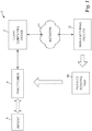
- FIG. 1 is a block diagram illustrating an exemplary computer environment 2 in which a client computing device 4 presents an environment for modeling a three-dimensional (3D) representation of a dental arch of a patient 6.
- a client computing device 4 presents an environment for modeling a three-dimensional (3D) representation of a dental arch of a patient 6.
- an orthodontic practitioner 8 interacts with modeling software executing on client computer device 4 to visualize the 3D representation of the dental arch, and precisely position "virtual" appliances (e.g., brackets) on individual teeth within the modeled dental arch.
- virtual appliances e.g., brackets
- the 3D representation of the dental arch may be initially generated by digitally scanning a physical dental impression of the teeth of patient 6 or by scanning a casting made from the impression.
- practitioner 8 may use an intraoral scanner to produce the 3D digital representation directly from the teeth of patient 6.
- Other methods of scanning could also be used, and the invention should not be limited to the methods described above.
- Practitioner 8 may interact with the modeling software to view the 3D digital representation of the teeth and to ultimately approve the point on each tooth where the respective bracket is to be located.
- the modeling software manipulates each bracket as a separate object within the 3D environment and fixes the position of each bracket within the 3D space relative to a coordinate system associated with the modeled tooth upon which the virtual bracket resides. Consequently, practitioner 8 may independently view and approve the precise location of each bracket within the 3D environment relative to its respective tooth.
- client computing device 4 may display and/or position any type of orthodontic appliance without departing from the scope of the present invention.
- orthodontic appliances include orthodontic brackets, buccal tubes, sheaths, buttons or archwires.
- client computing device 4 need not display a full visual representation of the appliance. Rather, a portion of the appliance may be displayed.
- client computing device 4 need not display the appliance itself. Rather, another object or graphical icon associated with an appliance or with the placement of an appliance may be shown instead of or in addition to the appliance itself.
- appliance examples include crosshairs (intersecting lines indicating the position on a tooth where the center of an appliance is to be placed), placement jigs, placement guides, or other peripherals which may represent or be attached to an appliance, or which may be otherwise associated with an appliance and/or its placement.
- appliance as used herein shall therefore be understood to include any type of appliance, a full or partial representation of an appliance, or any object associated with an appliance and/or its placement.
- Client computing device 4 may show a digital representation of an entire dental arch, a portion of a dental arch, an individual tooth within the dental arch, a portion of a tooth within the dental arch, or some combination thereof for viewing by practitioner 8.
- Client computing device 4 may also show a digital representation of appliances on all of the teeth in a dental arch, the appliances on a portion of the teeth in a dental arch, an appliance on a single tooth, or an appliance on a portion of a tooth.
- client computing device 4 may show a digital representation of an entire appliance, a portion of an appliance, or simply the crosshairs of an appliance (which may indicate, for example, the location on a tooth where the center of the appliance is to be placed). It shall be understood, therefore, that the image presented to the practitioner 8 by client computing device 4 may take many different forms, and that the invention is not limited in this respect.
- the modeling software automatically adjusts an orthodontic bracket to a desired mesio-distal position on a tooth within the 3D environment.
- the brackets may initially be placed in the 3D environment using the method described in copending and commonly assigned US Publication No. 2005/0130095 , entitled “Method Of Orienting An Orthodontic Appliance To A Tooth", to Raby, et al..
- Manual adjustment of orthodontic brackets may be assisted by use of visual planar guides, as described in copending and commonly assigned US Publication No. 2005/0170309 , entitled “Planar Guides to Visually Aid Orthodontic Appliance Placement within a Three-Dimensional (3D) Environment", to Raby, et al..
- a system visually aids the user in manual placement of brackets through manual adjustments to bracket position and orientation.
- brackets may also be automatically adjusted to a desired occlusal height on the tooth within the 3D environment either prior or subsequent to the mesio-distal positioning described herein using the techniques described in US Publication No. 2006/0024637 , entitled “Automatic Adjustment of an Orthodontic Bracket to a Desired Occlusal Height within a Three-Dimensional (3D) Environment", to Raby, et al..
- the modeling software automatically adjusts an orthodontic bracket within the 3D environment to a desired mesio-distal position on a tooth while simultaneously maintaining a desired fit between the bracket base and the tooth.
- the practitioner specifies a desired mesio-distal position at which the bracket is to be placed. Based on this desired mesio-distal position, the modeling software automatically adjusts the placement of the orthodontic bracket to the desired mesio-distal position on the tooth within the 3D environment while maintaining the desired fit.
- client computing device 4 communicates the bracket placement positions to manufacturing facility 12 via network 14.
- manufacturing facility 12 constructs an indirect bonding tray 16 for use in physically placing brackets on the teeth of patient 6.
- manufacturing facility 12 fabricates indirect bonding tray 16 based on the bracket placement positions selected by practitioner 8 within the 3D environment presented by client computing device 4.
- Manufacturing facility 12 may, for example, use conventional commercially available brackets selected by practitioner 8 to form indirect bonding tray 16.
- Manufacturing facility 12 forwards indirect bonding tray 16 to practitioner 8 for use in a conventional indirect bonding procedure to place the brackets on the teeth of patient 6.
- client computing device 4 need not forward the bracket placement positions to manufacturing facility 12.
- Client computing device 4 may instead output, e.g., display or print, the relevant distances and angles for each bracket to assist practitioner 8 in manually positioning the brackets on the teeth of patient 6.
- FIG. 2 is a block diagram illustrating an example embodiment of a client computing device 4 in further detail.
- client computing device 4 provides an operating environment for modeling software 20.
- modeling software 20 presents a modeling environment for modeling and depicting the 3D representation of the teeth of patient 6 ( FIG. 1 ).
- modeling software 20 includes a user interface 22, a mesio-distal position control module 24, and a rendering engine 26.
- User interface 22 provides a graphical user interface (GUI) that visually displays the 3D representation of the patient's teeth as well as 3D representations of the brackets.
- GUI graphical user interface
- user interface 22 provides an interface for receiving input from practitioner 8, e.g., via a keyboard and a pointing device, for manipulating the brackets and placing the brackets on respective teeth within the modeled dental arch.
- Modeling software 20 interacts with database 30 to access a variety of data, such as bracket data 32, 3D data 34, patient data 36, placement rules 40 and mesio-distal position data 42.
- Database 30 may be represented in a variety of forms including data storage files, lookup tables, or a database management system (DBMS) executing on one or more database servers.
- the database management system may be a relational (RDBMS), hierarchical (HDBMS), multi-dimensional (MDBMS), object oriented (ODBMS or OODBMS) or object relational (ORDBMS) database management system.
- the data may, for example, be stored within a single relational database, such as SQL Server from Microsoft Corporation.
- database 30 may be located remote from the client computing device and coupled to the client computing device via a public or private network, e.g., network 14.
- Modeling software 20, user interface 22, mesio-distal control module 24 and rendering engine 26 may comprise software instructions stored within a storage medium (e.g., disk, hard drive, solid state memory or the like) executable by one or more processors of client computing device 4.
- a storage medium e.g., disk, hard drive, solid state memory or the like
- Bracket data 32 describes a set of commercially available brackets that may be selected by practitioner 8 and positioned within the 3D modeling environment.
- bracket data 32 may store a variety of attributes for the commercially available brackets, such as dimensions, slot locations and characteristics, torque angles, angulations and other attributes.
- User interface 22 provides a menu-driven interface by which practitioner 8 selects the type of brackets for use in defining an orthodontic prescription for patient 6.
- Patient data 36 describes a set of one or more patients, e.g., patient 6, associated with practitioner 8.
- patient data 36 specifies general information, such as a name, birth date, and a dental history, for each patient.
- patient data 36 specifies a current prescription specified for each of the patients, including the types of brackets selected by practitioner 8 for use with each of the patients.
- Mesio-distal position data 42 specifies a set of mesio-distal positions and may be provided as default positions specified by libraries of virtual representations of industry-standard brackets.
- practitioner 8 may customize the default mesio-distal positions or specify new positions, for example, via user interface 22 for one or more teeth in the dentition.
- Mesio-distal position is one aspect of a patient's orthodontic prescription and, in one embodiment, is defined as the distance from the bracket origin (the center of the base of the bracket slot) to the mesial-most and distal-most points on the tooth, measured in the bracket slot coordinate system along the mesio-distal axis. Other definitions may readily be used.
- the bracket origin may be defined as the mesial-most point of the bracket slot, the distal-most point of the bracket, or any other point of reference relative to the bracket.
- the prescribed mesio-distal position affects the resulting aesthetic appearance of the teeth.
- a prescription generally include, among other aspects of a prescription, a set of mesio-distal positions that tend to satisfy the aesthetic requirements of most patients.
- a prescription specifies that the practitioner, such as practitioner 8, align the bracket so as to center the bracket along the mesio-distal axis of the tooth; however, the prescription may specify other positions offset from the center. Offset values typically comprise a few millimeters to either the mesial or distal direction along the center of this axis, such as a one millimeter distal offset or a two millimeter mesial offset from the center of the mesio-distal axis of the tooth.
- the standardized prescriptions may be used to achieve uniformity among patients or to avoid the more time consuming process of devising a custom set of mesio-distal positions for each tooth of an individual patient.
- User interface 22 may allow practitioner 8 to select one or more mesio-distal positions from the standardized prescriptions, and typically the practitioner selects a centered position along the mesio-distal axis.
- practitioner 8 may desire to create a customized set of mesio-distal positions to achieve a more aesthetically pleasing result, or to better take into account that patient's malocclusion.
- User interface 22 allows a practitioner to quantify the desired mesio-distal positions for each tooth as part of an overall prescription for a patient, whether the prescribed positions are customized or standardized. For some patients, a standardized set of mesio-distal positions for the teeth in the dentition may be satisfactory.
- practitioner 8 may create a customized set of mesio-distal positions for the teeth in the dentition by specifying mesio-distal offsets, as described above. As another example, a combination of standardized and customized mesio-distal positions throughout the dentition may be used.
- the desired mesio-distal positions are stored in database 30 as mesio-distal position data 42.
- Modeling software 20 then iteratively adjusts the locations and orientations of the brackets within the 3D environment to the prescribed mesio-distal positions automatically, and stores the result in patient data 36.
- mesio-distal position control module 24 receives mesio-distal position data 42 and automatically and iteratively adjusts the mesio-distal positions of the brackets associated with each tooth until the desired mesio-distal positions specified by mesio-distal position data 42 are achieved within a degree of acceptable tolerance.
- mesio-distal position control module 24 maintains a fit between the bracket base and the surface of the tooth.
- Placement rules 40 may specify industry-defined placement rules for commercially available brackets.
- placement rules 40 may include user-defined rules specified by practitioner 8 or other rules for controlling bracket placement.
- one rule for certain commercially available brackets is to align the medial line or longitudinal axis of the bracket with the Facial Axis of the Clinical Crown (FACC) of the tooth.
- the FACC is defined as the curved line formed by the intersection of the midsagittal plane and the facial surface of the tooth.
- Another exemplary industry-defined placement rule is to place the center of a base of the bracket on the FACC of the tooth equidistant from the occlusal edge or occlusal-most point on the FACC and the gingival margin of the crown. This location is also known as the Facial Axis Point (FA Point).
- modeling software 20 may allow the practitioner 8 to place the orthodontic appliance on the tooth so that certain placement rules are satisfied.
- practitioner 8 may desire to place a bracket at a mesio-distal position that is different from the FA Point. Consequently, practitioner 8 may specify different mesio-distal positions for different types of teeth in the dentition, for different types of brackets, for different customized prescriptions, or for combinations thereof.
- the desired mesio-distal position may be based in whole or in part on known rules associated with a particular type, or prescription, of the appliances selected by practitioner 8.
- Rendering engine 26 accesses and renders 3D data 34 to generate the 3D view presented to practitioner 8 by user interface 22. More specifically, 3D data 34 includes information defining the 3D objects that represent each tooth and bracket within the 3D environment. Rendering engine 26 processes each object to render a 3D triangular mesh surface based on a viewing perspective of practitioner 8 within the 3D environment. User interface 22 displays the rendered 3D triangular mesh to practitioner 8, and allows the practitioner to change viewing perspectives and manipulate objects within the 3D environment.
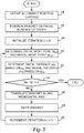
- FIG. 3 is a flowchart illustrating one exemplary method of automatically adjusting an orthodontic bracket to a desired mesio-distal position on a tooth within a 3D virtual environment. More specifically, the flowchart of FIG. 3 illustrates operation of mesio-distal control module 24 in automatically adjusting an orthodontic bracket within the 3D virtual environment to locate, orient and fit the bracket on a surface of a virtual representation of a tooth.
- the method shown in FIG. 3 may be used on anterior teeth (incisor or cuspid) as well as on posterior teeth (bicuspid or molar) and is described below in reference to FIGS. 4A-4G .
- FIGS. 4A-4G illustrate the method discussed above by which a client computing device, such as client computing device 4 of FIG. 2 , automatically adjusts the mesio-distal position of a virtual bracket upon a 3D representation of a tooth. While the method of FIG. 3 is described in reference to FIGS. 4A-4G , the method may be applied to any appliance, such as an orthodontic bracket, for automatic positioning to a desired mesio-distal location upon a surface of a virtual tooth. The method described below may follow or precede the automatic occlusal height adjustment of that same bracket, as described above, as automatic occlusal height adjustment may comprise a method independent or in conjunction with automatic mesio-distal positioning.
- any appliance such as an orthodontic bracket
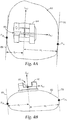
- FIGS. 4A and 4B show respective facial and occlusal views of a 3D representation of a crown of an anterior tooth 62 with a virtual orthodontic bracket 64 whose base is in optimal contact with tooth 62.
- the X s,i , y s,i , z s,i axes form the bracket slot coordinate system of bracket 64.
- "s" indicates the slot coordinate system
- "i” indicates the iteration number through the automatic bracket adjustment process as performed by mesio-distal control module 24.
- Bracket 64 includes a slot 66 in which an archwire may be threaded to fix the bracket to the tooth.
- the x s,i axis of the slot coordinate system is parallel to the slot 66 of bracket 64, as shown in FIG. 4A .
- the y s,i axis is perpendicular to the x s,i axis (and therefore perpendicular to slot 66 of bracket 64), and the z s,i axis is perpendicular to the plane defined by the y s,i and x s,i axes.
- both slot 66 and the x s,i axis are perpendicular to distal-most plane 68 and mesial-most plane 70 of tooth 62.
- Distal-most plane 68 is defined as a plane perpendicular to the x s,i axis and intersecting the distal-most point p di of the crown of tooth 62 for a given iteration i .
- mesial-most plane 70 is defined as a plane perpendicular to the x s,i axis and intersecting the mesial-most point p mi of the crown of tooth 62 for iteration i .
- distal distance is defined as the distance from distal-most plane 68 to the y s , i axis for iteration i
- mesial distance 78 is defined as the distance from mesial-most plane 70 to the y s , i axis for iteration i .
- a practitioner such as practitioner 8, may initially interact with client computing device 4 ( FIG. 2 ) to specify or select an allowable tolerance for any position error ( ⁇ ), which indicates the maximum allowable mesio-distal deviation from the desired mesio-distal position (44).
- the tolerance for any position error may be defined by modeling software 20 without requiring input from practitioner 8.
- Typical allowable position error values include 1/1000 th of an inch.
- Practitioner 8 may access patient data 36 to select or modify a prescription that indicates the desired appliance type, i.e., bracket 64, as well as the desired mesio-distal position, for each tooth in the dental arch.
- Practitioner 8 then directs client computing device 4 via a keyboard, mouse, or other input device to position bracket 64 upon tooth 62 (46).
- practitioner 8 may indicate an initial placement of bracket 64 via crosshairs or other such objects, as discussed above, and that placement may serve as an initial position for mesio-distal adjustment according to the process described below.
- the initial placement may be derived from a pre-defined standard or customized prescription selected by the practitioner 8 for the particular patient.
- Modeling software 20 may initially position bracket 64 using the method described in the above-referenced copending and commonly assigned U.S. Patent Application Publication Number 2005/0130095 .
- U.S. Patent Application Publication Number 2005/0130095 describes a method of placing a bracket on a tooth to attain a close, mating fit between the base of the bracket and the tooth surface.
- bracket 64 is placed within the 3D environment at an initial position of the facial surface of tooth 62, via either practitioner 8 or via modeling software 20, mesio-distal position control module 24 initializes the automatic mesio-distal adjustment process (48).
- Mesio-distal position control module 24 determines the distal-most and mesial-most points during each iteration.
- mesio-distal position control module 24 may translate all of the non-eliminated tooth points into bracket slot coordinate system x s,i , y s,i , z s,i' sort the points according to their x s,i axis values, and assign the distal-most point and mesial-most point to the values having the largest positive and negative x s,i values, respectively.
- mesio-distal position control module 24 may project all non-eliminated tooth points onto the s x,i axis of the bracket slot coordinate system and assign the distal-most point and mesial-most point to the values having the largest projected positive and negative x s,i values, respectively.
- mesio-distal position control module 24 typically calculates distal distance d i and mesial distance m i by respectively calculating the length of a line drawn perpendicular to both the y s , i axis and distal-most plane 68 and the length of a line drawn perpendicular to both the y s,i axis and mesial-most plane 70.
- mesio-distal position control module 24 determines whether the absolute value of the difference between distal distance d i and mesial distance m i is less than or equal to the allowable positional error ⁇ , as expressed mathematically by the equation:
- ⁇ ⁇ (54). If this difference does not exceed the allowable positional error ⁇ , then bracket 64 need not be adjusted further, and the automatic mesio-distal adjustment process is finished ("YES" branch 54). However, if this difference exceeds the allowable positional error ⁇ , then further adjustment of bracket 64 is required ("NO" branch 54).
- mesio-distal position control module 24 determines the bracket mesio-distal translation distance, i.e., the amount that the bracket should be moved along the mesio-distal axis based on the current mesial distance m i and distal distance d i , and adjusts the location of bracket 64 within the 3D environment by the determined distance along the current mesio-distal axis x s,i (56). In some embodiments, mesio-distal position control module 24 determines the bracket mesio-distal translation distance based on further information, such as the desired mesio-distal position.
- patient 6 may require bracket 64 to be placed at a mesio-distal position that is not centered on tooth 62, and this may be specified as a mesio-distal offset in patient data 36.
- Mesio-distal position control module 24 may access this offset within patient data 36 and vary its automatic mesio-distal adjustment property to compensate for this offset.
- mesio-distal position control module 24 determines which direction along the mesio-distal axis to translate and the distance to translate by subtracting the mesial distance m i from the distal distance d i and adjusting for any mesio-distal offset. For ease of illustration, it is assumed that no mesio-distal offset was specified or, in other words, that mesio-distal position control module 24 should center bracket 64 on the facial surface of tooth 62.
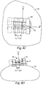
- FIGS. 4C and 4D show facial and occlusal views, respectively, of the result of a first translation of bracket 64 along tooth 62. Both FIGS. 4C and 4D also show the previous location of bracket 64 as phantom (dashed) lines.
- mesio-distal position control module 24 translated bracket 64 by a distance of the absolute value of the difference between mesial distance m i and distal distance d i divided by two, which can be mathematically represented by the following equation:
- mesio-distal position control module 24 translated bracket 64 mesially along the mesio-distal axis defined by the bracket slot coordinate system x s,i , y s,i , z s,i.
- FIG. 4E shows another occlusal view of tooth 62 of FIG. 4A with bracket 64 translated after one or more iterations until reaching the desired mesio-distal point along the x s , i axis of the bracket slot coordinate system.
- mesial distance m i approximately equals distal distance d i .
- the base of bracket 64 may not maintain optimal contact with tooth 62. Assuming the prescription stored in patient data 36 specifies no mesio-distal offset, bracket 64 resides at the desired mesio-distal point, albeit without maintaining optimal contact with tooth 62.
- mesio-distal position control module 24 may refit bracket 64 on tooth 62 after each translation in order to optimize contact between the base of bracket 64 and the facial surface of tooth 62 (58).
- One way to achieve this is to refit the bracket to achieve a close mating fit between the bracket and the tooth surface using the method described in U.S. Patent Application Publication No. 2005/0130095 .
- FIG. 4F shows an occlusal view of tooth 62 of FIG. 4A with bracket 64 positioned at the desired mesio-distal position after bracket 64 has been automatically refit to maintain optimal facial contact with tooth 62.
- Phantom (dashed) lines represent the previous position of bracket 64 and serves to illustrate the readjustment of bracket 64 resulting from the refit process.
- Mesio-distal position control module 24 also determines distal distance d i based on distal-most point p di and mesial distance m i based on the mesial-most point p mi for the current iteration i , as described above (52).
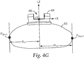
- FIG. 4G shows an occlusal view of tooth 62 with the base of bracket 64 in optimal contact with tooth 62.
- FIG. 4G also shows distal-most point p di+1 , mesial-most point p mi+1 , distal distance d i+1 , and mesial distance m i+1. Due to the refit of bracket 64 to tooth 62, distal distance d i+1 may no longer approximately equal mesial distance m i+1 within the allowable position error ⁇ .
- mesio-distal position control module 24 after calculating distal distance d i+1 and mesial distance m 1+1 , determines whether the absolute value of the difference between distal distance d i+1 and mesial distance m i+1 is less than or equal to allowable position error ⁇ (54). If less than allowable position error ⁇ ("YES" branch 54), mesio-distal position control module 24 makes no further mesio-distal position adjustments and the automatic mesio-distal adjustment process is finished. However, if more than allowable position error ⁇ ("NO" branch 54), mesio-distal position control module 24 continues the automatic mesio-distal adjustment process, as described above.
- mesio-distal position control module 24 may be programmed to detect one or more conditions that would result in incorrect placement of bracket 64 on tooth 62.
- One such condition includes instances where, after translation, bracket 64 would intersect or be positioned below a tolerance distance relative to a tooth or bracket adjacent to tooth 62. In these instances, mesio-distal position control module 24 may flag the potential collision with the adjacent tooth or bracket and bring the collision to the attention of practitioner 8. In other embodiments, mesio-distal position control module 24 translates bracket 64 to a position as far as possible along the mesio-distal axis that avoids collision with the adjacent tooth and bracket.
- mesio-distal position control module 24 translates bracket 64 to a position along the mesio-distal axis but retains some pre-defined distance from the adjacent tooth and/or bracket. The distance may be useful to provide sufficient space to allow for the archwire to be threaded through slot 66 of bracket 64 once applied to the patient.
- the automatic mesio-distal adjustment process may occur in any number of ways.
- practitioner 8 may place all brackets on each prescribed tooth and then perform the mesio-distal adjustment process.
- practitioner 8 may place one bracket on a prescribed tooth, perform the automatic mesio-distal adjustment process, and repeat for each prescribed tooth.
- practitioner 8 may place one bracket on a prescribed tooth, perform the automatic mesio-distal adjustment process and, simultaneous to performing the automatic adjustment, place another bracket on another prescribed tooth.
Landscapes
- Health & Medical Sciences (AREA)
- Public Health (AREA)
- Epidemiology (AREA)
- General Health & Medical Sciences (AREA)
- Medical Informatics (AREA)
- Engineering & Computer Science (AREA)
- Primary Health Care (AREA)
- Life Sciences & Earth Sciences (AREA)
- Veterinary Medicine (AREA)
- Nuclear Medicine, Radiotherapy & Molecular Imaging (AREA)
- Radiology & Medical Imaging (AREA)
- Animal Behavior & Ethology (AREA)
- Dentistry (AREA)
- Oral & Maxillofacial Surgery (AREA)
- Biomedical Technology (AREA)
- Data Mining & Analysis (AREA)
- Databases & Information Systems (AREA)
- Pathology (AREA)
- Dental Tools And Instruments Or Auxiliary Dental Instruments (AREA)
Description
- The invention relates to electronic orthodontics and, more particularly, computer-based techniques for assisting orthodontic diagnosis and treatment.
- The field of orthodontics is concerned with repositioning and aligning a patient's teeth for improved occlusion and aesthetic appearance. For example, orthodontic treatment often involves the use of tiny slotted appliances, known as brackets, which are fixed to the patient's anterior, cuspid, and bicuspid teeth. An archwire is received in the slot of each bracket and serves as a track to guide movement of the teeth to desired orientations. The ends of the archwire are usually received in appliances known as buccal tubes that are secured to the patient's molar teeth.
- A number of orthodontic appliances in commercial use today are constructed on the principle of the "straight wire concept" developed by Dr. Lawrence F. Andrews, D.D.S. In accordance with this concept, the shape of the appliances, including the orientation of the slots of the appliances, is selected so that the slots are aligned in a flat reference plane at the conclusion of treatment. Additionally, a resilient archwire is selected with an overall curved shape that normally lies in a flat reference plane.
- When the archwire is placed in the slots of the straight wire appliances at the beginning of orthodontic treatment, the archwire is often deflected upwardly or downwardly or torqued from one appliance to the next in accordance with the patient's malocclusion. However, the resiliency of the archwire tends to return the archwire to its normally curved shape that lies in the flat reference plane. As the archwire shifts toward the flat reference plane, the attached teeth are moved in a corresponding fashion toward an aligned, aesthetically pleasing array.
- As can be appreciated, it is important for the practitioner using straight wire appliances to precisely fix each bracket in the proper position on the corresponding tooth. If, for example, a bracket is placed too far in an occlusal direction on the tooth surface, the archwire will tend to position the crown of the tooth too close to the gingiva (gums) at the end of the treatment. As another example, if the bracket is placed to one side of the center of the tooth in either the mesial or distal directions, the resultant tooth orientation will likely be an orientation that is excessively rotated about its long axis.
- The process of positioning and bonding the brackets to the patient's teeth requires considerable care, and requires the practitioner to visually determine the proper location of the brackets on the respective teeth. Often, a practitioner determines bracket positions by the use of a ruler, protractor and pencil to measure and mark features on a plaster cast made from impressions of the patient's teeth. This process is often difficult to carry out with precision, and may be subjective in nature. Consequently, it is often difficult for the practitioner to ensure that the brackets are precisely positioned on the teeth at correct locations.
-
US 2006/0024637 A1 discloses a system that automatically adjusts an orthodontic bracket to a desired occlusal height on a tooth within a 3D environment. -
US 2005/0170309 A1 discloses a system that includes modeling software executing on a computing device to provide a three-dimensional (3D) environment. The modeling software comprises a rendering engine that renders a digital representation of a dental arch within the 3D environment, and a user interface that displays a planar guide within the 3D environment as a visual aid to a practitioner in the placement of an orthodontic appliance relative to the dental arch. - According to the invention, a computer-implemented method, a system, and a computer-readable medium as recited in the independent claims are provided. The dependent claims define embodiments.
- In general, the invention relates to computer-implemented techniques for assisting practitioners in orthodontic diagnosis and treatment. More specifically, a computing system is described that provides an environment for modeling and depicting a three-dimensional (3D) representation of a patient's dental arch. By interacting with the system, orthodontic practitioners are able to visualize the 3D representation of the dental arch, and precisely position "virtual" orthodontic appliances relative to the modeled dental arch. For example, the orthodontic practitioner may interact with the system to position brackets on one or more teeth within the modeled dental arch.
- As described in detail herein, the system allows the practitioner to pre-define a desired mesio-distal position at which a particular bracket is to be placed on a given tooth. The mesio-distal position may be defined as the distance from a bracket origin (e.g., the center of the base of the bracket slot) to both a distal-most point and mesial-most point on the tooth measured along the mesio-distal axis of the bracket. The desired mesio-distal position may be chosen from a standardized set of mesio-distal positions or may be customized by the practitioner to the particular needs of a patient, e.g., the practitioner may specify a mesio-distal offset from the center of the mesio-distal axis.
- Based on the defined mesio-distal position, the computing system executes software to automatically adjust and orient the virtual bracket within the 3D environment. Through a series of computational iterations, the system automatically adjusts the mesio-distal position of the virtual bracket until the mesio-distal position closely approximates the desired mesio-distal position. In some embodiments, the system may eliminate portions of the 3D modeling data and surface structure of the virtual tooth to more accurately center the bracket on the facial surface of the tooth. The system eliminates 3D data associated with a lingual surface of the tooth in order to more accurately position the bracket in a mesio-distal position on the facial surface of the tooth.
- Once the updated mesio-distal location and orientation of the bracket have been computed, the system visually represents the resulting bracket placement within the 3D environment. The automatic bracket adjustment and the visual representation aid the practitioner in achieving the desired bracket placement on the tooth.
- In one embodiment, the invention is directed to a method comprising rendering a digital representation of at least a portion of a tooth within a three-dimensional (3D) environment, receiving a desired mesio-distal position for an orthodontic appliance associated with the tooth, and automatically adjusting the orthodontic appliance to the desired mesio-distal position on the tooth within the 3D environment.
- In another embodiment, the invention is directed to a system comprising a computing device and modeling software executing on the computing device. The modeling software comprises a rendering engine that renders a digital representation of at least a portion of a tooth within a three-dimensional (3D) environment, and a mesio-distal position control module that automatically adjusts an orthodontic appliance to a desired mesio-distal position on the tooth within the 3D environment.
- In another embodiment, the invention is directed to a computer-readable medium containing instructions. The instructions cause a programmable processor to render a digital representation of at least a portion of a tooth within a three-dimensional (3D) environment, receive a desired mesio-distal position for an orthodontic appliance associated with the tooth, and automatically adjust the orthodontic appliance to the desired mesio-distal position on the tooth within the 3D environment.
- The details of one or more embodiments of the invention are set forth in the accompanying drawings and the description below. Other features, objects, and advantages of the invention will be apparent from the description and drawings, and from the claims.
-
-
FIG. 1 is a block diagram illustrating an exemplary computer environment in which a client computing device presents an environment for modeling a three-dimensional (3D) representation of a dental arch of a patient. -
FIG. 2 is a block diagram illustrating an example embodiment of a client computing device in further detail. -
FIG. 3 is a flowchart illustrating one example method of automatically adjusting an orthodontic bracket to a desired mesio-distal position on a tooth. -
FIGS. 4A-4G illustrate the method by which a client computing device automatically adjusts the mesio-distal position of a virtual bracket upon a 3D representation of a tooth. -
FIG. 1 is a block diagram illustrating anexemplary computer environment 2 in which aclient computing device 4 presents an environment for modeling a three-dimensional (3D) representation of a dental arch of a patient 6. In this example, anorthodontic practitioner 8 interacts with modeling software executing onclient computer device 4 to visualize the 3D representation of the dental arch, and precisely position "virtual" appliances (e.g., brackets) on individual teeth within the modeled dental arch. - The 3D representation of the dental arch may be initially generated by digitally scanning a physical dental impression of the teeth of patient 6 or by scanning a casting made from the impression. Alternatively,
practitioner 8 may use an intraoral scanner to produce the 3D digital representation directly from the teeth of patient 6. Other methods of scanning could also be used, and the invention should not be limited to the methods described above.Practitioner 8 may interact with the modeling software to view the 3D digital representation of the teeth and to ultimately approve the point on each tooth where the respective bracket is to be located. During this process, the modeling software manipulates each bracket as a separate object within the 3D environment and fixes the position of each bracket within the 3D space relative to a coordinate system associated with the modeled tooth upon which the virtual bracket resides. Consequently,practitioner 8 may independently view and approve the precise location of each bracket within the 3D environment relative to its respective tooth. - Although the description will generally discuss the display and positioning of orthodontic brackets, it shall be understood that
client computing device 4 may display and/or position any type of orthodontic appliance without departing from the scope of the present invention. Examples of such orthodontic appliances include orthodontic brackets, buccal tubes, sheaths, buttons or archwires. In addition,client computing device 4 need not display a full visual representation of the appliance. Rather, a portion of the appliance may be displayed. As another alternative,client computing device 4 need not display the appliance itself. Rather, another object or graphical icon associated with an appliance or with the placement of an appliance may be shown instead of or in addition to the appliance itself. Examples of such other objects include crosshairs (intersecting lines indicating the position on a tooth where the center of an appliance is to be placed), placement jigs, placement guides, or other peripherals which may represent or be attached to an appliance, or which may be otherwise associated with an appliance and/or its placement. The term "appliance" as used herein shall therefore be understood to include any type of appliance, a full or partial representation of an appliance, or any object associated with an appliance and/or its placement. -
Client computing device 4 may show a digital representation of an entire dental arch, a portion of a dental arch, an individual tooth within the dental arch, a portion of a tooth within the dental arch, or some combination thereof for viewing bypractitioner 8.Client computing device 4 may also show a digital representation of appliances on all of the teeth in a dental arch, the appliances on a portion of the teeth in a dental arch, an appliance on a single tooth, or an appliance on a portion of a tooth. Similarly,client computing device 4 may show a digital representation of an entire appliance, a portion of an appliance, or simply the crosshairs of an appliance (which may indicate, for example, the location on a tooth where the center of the appliance is to be placed). It shall be understood, therefore, that the image presented to thepractitioner 8 byclient computing device 4 may take many different forms, and that the invention is not limited in this respect. - As described in detail herein, the modeling software automatically adjusts an orthodontic bracket to a desired mesio-distal position on a tooth within the 3D environment. The brackets may initially be placed in the 3D environment using the method described in copending and commonly assigned
US Publication No. 2005/0130095 , entitled "Method Of Orienting An Orthodontic Appliance To A Tooth", to Raby, et al.. Manual adjustment of orthodontic brackets may be assisted by use of visual planar guides, as described in copending and commonly assignedUS Publication No. 2005/0170309 , entitled "Planar Guides to Visually Aid Orthodontic Appliance Placement within a Three-Dimensional (3D) Environment", to Raby, et al.. In that application, a system visually aids the user in manual placement of brackets through manual adjustments to bracket position and orientation. - Moreover, the brackets may also be automatically adjusted to a desired occlusal height on the tooth within the 3D environment either prior or subsequent to the mesio-distal positioning described herein using the techniques described in
US Publication No. 2006/0024637 , entitled "Automatic Adjustment of an Orthodontic Bracket to a Desired Occlusal Height within a Three-Dimensional (3D) Environment", to Raby, et al.. - In accordance with the techniques described herein, the modeling software automatically adjusts an orthodontic bracket within the 3D environment to a desired mesio-distal position on a tooth while simultaneously maintaining a desired fit between the bracket base and the tooth. In some embodiments, the practitioner specifies a desired mesio-distal position at which the bracket is to be placed. Based on this desired mesio-distal position, the modeling software automatically adjusts the placement of the orthodontic bracket to the desired mesio-distal position on the tooth within the 3D environment while maintaining the desired fit.
- Once the brackets are placed and the practitioner has indicated his or her approval,
client computing device 4 communicates the bracket placement positions tomanufacturing facility 12 vianetwork 14. In response, manufacturingfacility 12 constructs anindirect bonding tray 16 for use in physically placing brackets on the teeth of patient 6. In other words, manufacturingfacility 12 fabricatesindirect bonding tray 16 based on the bracket placement positions selected bypractitioner 8 within the 3D environment presented byclient computing device 4.Manufacturing facility 12 may, for example, use conventional commercially available brackets selected bypractitioner 8 to formindirect bonding tray 16.Manufacturing facility 12 forwardsindirect bonding tray 16 topractitioner 8 for use in a conventional indirect bonding procedure to place the brackets on the teeth of patient 6. - Alternatively,
client computing device 4 need not forward the bracket placement positions tomanufacturing facility 12.Client computing device 4 may instead output, e.g., display or print, the relevant distances and angles for each bracket to assistpractitioner 8 in manually positioning the brackets on the teeth of patient 6. -
FIG. 2 is a block diagram illustrating an example embodiment of aclient computing device 4 in further detail. In the illustrated embodiment,client computing device 4 provides an operating environment formodeling software 20. As described above,modeling software 20 presents a modeling environment for modeling and depicting the 3D representation of the teeth of patient 6 (FIG. 1 ). In the illustrated embodiment,modeling software 20 includes auser interface 22, a mesio-distalposition control module 24, and arendering engine 26. -
User interface 22 provides a graphical user interface (GUI) that visually displays the 3D representation of the patient's teeth as well as 3D representations of the brackets. In addition,user interface 22 provides an interface for receiving input frompractitioner 8, e.g., via a keyboard and a pointing device, for manipulating the brackets and placing the brackets on respective teeth within the modeled dental arch. -
Modeling software 20 interacts withdatabase 30 to access a variety of data, such asbracket data 3D data 34,patient data 36, placement rules 40 and mesio-distal position data 42.Database 30 may be represented in a variety of forms including data storage files, lookup tables, or a database management system (DBMS) executing on one or more database servers. The database management system may be a relational (RDBMS), hierarchical (HDBMS), multi-dimensional (MDBMS), object oriented (ODBMS or OODBMS) or object relational (ORDBMS) database management system. The data may, for example, be stored within a single relational database, such as SQL Server from Microsoft Corporation. Although illustrated as local toclient computing device 4,database 30 may be located remote from the client computing device and coupled to the client computing device via a public or private network, e.g.,network 14. -
Modeling software 20,user interface 22, mesio-distal control module 24 andrendering engine 26 may comprise software instructions stored within a storage medium (e.g., disk, hard drive, solid state memory or the like) executable by one or more processors ofclient computing device 4. -
Bracket data 32 describes a set of commercially available brackets that may be selected bypractitioner 8 and positioned within the 3D modeling environment. For example,bracket data 32 may store a variety of attributes for the commercially available brackets, such as dimensions, slot locations and characteristics, torque angles, angulations and other attributes.User interface 22 provides a menu-driven interface by whichpractitioner 8 selects the type of brackets for use in defining an orthodontic prescription for patient 6. -
Patient data 36 describes a set of one or more patients, e.g., patient 6, associated withpractitioner 8. For example,patient data 36 specifies general information, such as a name, birth date, and a dental history, for each patient. In addition,patient data 36 specifies a current prescription specified for each of the patients, including the types of brackets selected bypractitioner 8 for use with each of the patients. - Mesio-
distal position data 42 specifies a set of mesio-distal positions and may be provided as default positions specified by libraries of virtual representations of industry-standard brackets. In addition,practitioner 8 may customize the default mesio-distal positions or specify new positions, for example, viauser interface 22 for one or more teeth in the dentition. Mesio-distal position is one aspect of a patient's orthodontic prescription and, in one embodiment, is defined as the distance from the bracket origin (the center of the base of the bracket slot) to the mesial-most and distal-most points on the tooth, measured in the bracket slot coordinate system along the mesio-distal axis. Other definitions may readily be used. For example, the bracket origin may be defined as the mesial-most point of the bracket slot, the distal-most point of the bracket, or any other point of reference relative to the bracket. The prescribed mesio-distal position affects the resulting aesthetic appearance of the teeth. - The orthodontic industry has developed standard prescriptions for many commercially available orthodontic brackets. These standardized prescriptions generally include, among other aspects of a prescription, a set of mesio-distal positions that tend to satisfy the aesthetic requirements of most patients. Typically, a prescription specifies that the practitioner, such as
practitioner 8, align the bracket so as to center the bracket along the mesio-distal axis of the tooth; however, the prescription may specify other positions offset from the center. Offset values typically comprise a few millimeters to either the mesial or distal direction along the center of this axis, such as a one millimeter distal offset or a two millimeter mesial offset from the center of the mesio-distal axis of the tooth. The standardized prescriptions may be used to achieve uniformity among patients or to avoid the more time consuming process of devising a custom set of mesio-distal positions for each tooth of an individual patient.User interface 22 may allowpractitioner 8 to select one or more mesio-distal positions from the standardized prescriptions, and typically the practitioner selects a centered position along the mesio-distal axis. - With some patients,
practitioner 8 may desire to create a customized set of mesio-distal positions to achieve a more aesthetically pleasing result, or to better take into account that patient's malocclusion.User interface 22 allows a practitioner to quantify the desired mesio-distal positions for each tooth as part of an overall prescription for a patient, whether the prescribed positions are customized or standardized. For some patients, a standardized set of mesio-distal positions for the teeth in the dentition may be satisfactory. Alternatively,practitioner 8 may create a customized set of mesio-distal positions for the teeth in the dentition by specifying mesio-distal offsets, as described above. As another example, a combination of standardized and customized mesio-distal positions throughout the dentition may be used. The desired mesio-distal positions are stored indatabase 30 as mesio-distal position data 42. -
Modeling software 20 then iteratively adjusts the locations and orientations of the brackets within the 3D environment to the prescribed mesio-distal positions automatically, and stores the result inpatient data 36. In particular, mesio-distalposition control module 24 receives mesio-distal position data 42 and automatically and iteratively adjusts the mesio-distal positions of the brackets associated with each tooth until the desired mesio-distal positions specified by mesio-distal position data 42 are achieved within a degree of acceptable tolerance. During the process, mesio-distalposition control module 24 maintains a fit between the bracket base and the surface of the tooth. - Placement rules 40 may specify industry-defined placement rules for commercially available brackets. In addition, placement rules 40 may include user-defined rules specified by
practitioner 8 or other rules for controlling bracket placement. For example, one rule for certain commercially available brackets is to align the medial line or longitudinal axis of the bracket with the Facial Axis of the Clinical Crown (FACC) of the tooth. The FACC is defined as the curved line formed by the intersection of the midsagittal plane and the facial surface of the tooth. Another exemplary industry-defined placement rule is to place the center of a base of the bracket on the FACC of the tooth equidistant from the occlusal edge or occlusal-most point on the FACC and the gingival margin of the crown. This location is also known as the Facial Axis Point (FA Point). By automatically adjusting the bracket to a specified mesio-distal position,modeling software 20 may allow thepractitioner 8 to place the orthodontic appliance on the tooth so that certain placement rules are satisfied. - As another example,
practitioner 8 may desire to place a bracket at a mesio-distal position that is different from the FA Point. Consequently,practitioner 8 may specify different mesio-distal positions for different types of teeth in the dentition, for different types of brackets, for different customized prescriptions, or for combinations thereof. Optionally, the desired mesio-distal position may be based in whole or in part on known rules associated with a particular type, or prescription, of the appliances selected bypractitioner 8. -
Rendering engine 26 accesses and renders3D data 34 to generate the 3D view presented topractitioner 8 byuser interface 22. More specifically,3D data 34 includes information defining the 3D objects that represent each tooth and bracket within the 3D environment.Rendering engine 26 processes each object to render a 3D triangular mesh surface based on a viewing perspective ofpractitioner 8 within the 3D environment.User interface 22 displays the rendered 3D triangular mesh topractitioner 8, and allows the practitioner to change viewing perspectives and manipulate objects within the 3D environment. -
FIG. 3 is a flowchart illustrating one exemplary method of automatically adjusting an orthodontic bracket to a desired mesio-distal position on a tooth within a 3D virtual environment. More specifically, the flowchart ofFIG. 3 illustrates operation of mesio-distal control module 24 in automatically adjusting an orthodontic bracket within the 3D virtual environment to locate, orient and fit the bracket on a surface of a virtual representation of a tooth. The method shown inFIG. 3 may be used on anterior teeth (incisor or cuspid) as well as on posterior teeth (bicuspid or molar) and is described below in reference toFIGS. 4A-4G . - In general,
FIGS. 4A-4G illustrate the method discussed above by which a client computing device, such asclient computing device 4 ofFIG. 2 , automatically adjusts the mesio-distal position of a virtual bracket upon a 3D representation of a tooth. While the method ofFIG. 3 is described in reference toFIGS. 4A-4G , the method may be applied to any appliance, such as an orthodontic bracket, for automatic positioning to a desired mesio-distal location upon a surface of a virtual tooth. The method described below may follow or precede the automatic occlusal height adjustment of that same bracket, as described above, as automatic occlusal height adjustment may comprise a method independent or in conjunction with automatic mesio-distal positioning. -
FIGS. 4A and 4B show respective facial and occlusal views of a 3D representation of a crown of ananterior tooth 62 with a virtualorthodontic bracket 64 whose base is in optimal contact withtooth 62. In bothFIGS. 4A and 4B , the Xs,i, ys,i, zs,i axes form the bracket slot coordinate system ofbracket 64. In this notation, "s" indicates the slot coordinate system and "i" indicates the iteration number through the automatic bracket adjustment process as performed by mesio-distal control module 24.Bracket 64 includes aslot 66 in which an archwire may be threaded to fix the bracket to the tooth. In one embodiment, the xs,i axis of the slot coordinate system is parallel to theslot 66 ofbracket 64, as shown inFIG. 4A . In this embodiment, the ys,i axis is perpendicular to the xs,i axis (and therefore perpendicular to slot 66 of bracket 64), and the zs,i axis is perpendicular to the plane defined by the ys,i and xs,i axes. - Also, both
slot 66 and the xs,i axis are perpendicular todistal-most plane 68 andmesial-most plane 70 oftooth 62.Distal-most plane 68 is defined as a plane perpendicular to the xs,i axis and intersecting the distal-most point pdi of the crown oftooth 62 for a given iteration i. Similarly,mesial-most plane 70 is defined as a plane perpendicular to the xs,i axis and intersecting the mesial-most point pmi of the crown oftooth 62 for iteration i. For purposes of this example, distal distance ("di") is defined as the distance fromdistal-most plane 68 to the ys,i axis for iteration i, and mesial distance 78 ("mi") is defined as the distance frommesial-most plane 70 to the ys,i axis for iteration i. - Referring again to the method of
FIG. 3 , a practitioner, such aspractitioner 8, may initially interact with client computing device 4 (FIG. 2 ) to specify or select an allowable tolerance for any position error (ε), which indicates the maximum allowable mesio-distal deviation from the desired mesio-distal position (44). Alternatively, the tolerance for any position error may be defined by modelingsoftware 20 without requiring input frompractitioner 8. Typical allowable position error values include 1/1000th of an inch.Practitioner 8 may accesspatient data 36 to select or modify a prescription that indicates the desired appliance type, i.e.,bracket 64, as well as the desired mesio-distal position, for each tooth in the dental arch. -
Practitioner 8 then directsclient computing device 4 via a keyboard, mouse, or other input device to positionbracket 64 upon tooth 62 (46). In some cases,practitioner 8 may indicate an initial placement ofbracket 64 via crosshairs or other such objects, as discussed above, and that placement may serve as an initial position for mesio-distal adjustment according to the process described below. Alternatively, the initial placement may be derived from a pre-defined standard or customized prescription selected by thepractitioner 8 for the particular patient.Modeling software 20 may initially positionbracket 64 using the method described in the above-referenced copending and commonly assignedU.S. Patent Application Publication Number 2005/0130095 . Generally,U.S. Patent Application Publication Number 2005/0130095 describes a method of placing a bracket on a tooth to attain a close, mating fit between the base of the bracket and the tooth surface. - Once
bracket 64 is placed within the 3D environment at an initial position of the facial surface oftooth 62, via eitherpractitioner 8 or viamodeling software 20, mesio-distalposition control module 24 initializes the automatic mesio-distal adjustment process (48). In particular, upon receiving a request to automatically adjust the position ofbracket 64, mesio-distalposition control module 24 withinclient computing device 4 begins the automatic placement by initializing an iteration variable (i) to zero, or i = 0, for the first time through the automatic adjustment process (46,FIG. 3 ). - Next, mesio-distal
position control module 24 determines, for iteration i = 0, distal-most point pdi and mesial-most point pmi relative to the xs,i axis of the bracket slot coordinate system xs,i, ys,i, zs,i (50). In some embodiments, mesio-distalposition control module 24 reduces the number of calculations per iteration, and potentially reduces the possibility for incorrect automatic adjustment, by eliminating some portions of the virtual surface structure oftooth 62 in order to more accurately calculate the mesial-most and distal-most points for each iteration. Mesio-distalposition control module 24 eliminates points on the lingual surface, or non-facial surface, oftooth 62 in order to more accurately centerbracket 64 to the facial surface instead of the entire tooth. - Mesio-distal
position control module 24 determines the distal-most and mesial-most points during each iteration. In one approach, mesio-distalposition control module 24 may translate all of the non-eliminated tooth points into bracket slot coordinate system xs,i, ys,i, zs,i' sort the points according to their xs,i axis values, and assign the distal-most point and mesial-most point to the values having the largest positive and negative xs,i values, respectively. In other embodiments, mesio-distalposition control module 24 may project all non-eliminated tooth points onto the sx,i axis of the bracket slot coordinate system and assign the distal-most point and mesial-most point to the values having the largest projected positive and negative xs,i values, respectively. - Inherent to calculating these points, mesio-distal
position control module 24 also calculatesdistal-most plane 68 andmesial-most plane 70 by constructing both planes parallel to the ys,i axis and intersecting distal-most point pdi and mesial-most point pmi, respectively. After calculatingplanes position control module 24 determines, again for iteration i = 0, distal distance di based on distal-most point pdi and mesial distance mi based on mesial-most point pmi. More specifically, mesio-distalposition control module 24 typically calculates distal distance di and mesial distance mi by respectively calculating the length of a line drawn perpendicular to both the ys,i axis anddistal-most plane 68 and the length of a line drawn perpendicular to both the ys,i axis andmesial-most plane 70. - Upon calculating distal distance di and mesial distance mi, mesio-distal
position control module 24 determines whether the absolute value of the difference between distal distance di and mesial distance mi is less than or equal to the allowable positional error ε, as expressed mathematically by the equation: |mi- di| <= ε (54). If this difference does not exceed the allowable positional error ε, thenbracket 64 need not be adjusted further, and the automatic mesio-distal adjustment process is finished ("YES" branch 54). However, if this difference exceeds the allowable positional error ε, then further adjustment ofbracket 64 is required ("NO" branch 54). - In instances where further adjustment is required, mesio-distal
position control module 24 determines the bracket mesio-distal translation distance, i.e., the amount that the bracket should be moved along the mesio-distal axis based on the current mesial distance mi and distal distance di, and adjusts the location ofbracket 64 within the 3D environment by the determined distance along the current mesio-distal axis xs,i (56). In some embodiments, mesio-distalposition control module 24 determines the bracket mesio-distal translation distance based on further information, such as the desired mesio-distal position. For example, patient 6 may requirebracket 64 to be placed at a mesio-distal position that is not centered ontooth 62, and this may be specified as a mesio-distal offset inpatient data 36. Mesio-distalposition control module 24 may access this offset withinpatient data 36 and vary its automatic mesio-distal adjustment property to compensate for this offset. Typically, mesio-distalposition control module 24 determines which direction along the mesio-distal axis to translate and the distance to translate by subtracting the mesial distance mi from the distal distance di and adjusting for any mesio-distal offset. For ease of illustration, it is assumed that no mesio-distal offset was specified or, in other words, that mesio-distalposition control module 24 should centerbracket 64 on the facial surface oftooth 62. -
FIGS. 4C and 4D show facial and occlusal views, respectively, of the result of a first translation ofbracket 64 alongtooth 62. BothFIGS. 4C and 4D also show the previous location ofbracket 64 as phantom (dashed) lines. In the illustrated example, mesio-distalposition control module 24 translatedbracket 64 by a distance of the absolute value of the difference between mesial distance mi and distal distance di divided by two, which can be mathematically represented by the following equation: |mi - di| / 2. Further, mesio-distalposition control module 24 translatedbracket 64 mesially along the mesio-distal axis defined by the bracket slot coordinate system xs,i, ys,i, zs,i. -
FIG. 4E shows another occlusal view oftooth 62 ofFIG. 4A withbracket 64 translated after one or more iterations until reaching the desired mesio-distal point along the xs,i axis of the bracket slot coordinate system. In the illustrated example, mesial distance mi approximately equals distal distance di. However, after each translation, the base ofbracket 64 may not maintain optimal contact withtooth 62. Assuming the prescription stored inpatient data 36 specifies no mesio-distal offset,bracket 64 resides at the desired mesio-distal point, albeit without maintaining optimal contact withtooth 62. - Referring again to
FIG. 3 , mesio-distalposition control module 24 may refitbracket 64 ontooth 62 after each translation in order to optimize contact between the base ofbracket 64 and the facial surface of tooth 62 (58). One way to achieve this is to refit the bracket to achieve a close mating fit between the bracket and the tooth surface using the method described inU.S. Patent Application Publication No. 2005/0130095 . -
FIG. 4F shows an occlusal view oftooth 62 ofFIG. 4A withbracket 64 positioned at the desired mesio-distal position afterbracket 64 has been automatically refit to maintain optimal facial contact withtooth 62. Phantom (dashed) lines represent the previous position ofbracket 64 and serves to illustrate the readjustment ofbracket 64 resulting from the refit process. - Referring once again to
FIG. 3 , after refittingbracket 64, mesio-distalposition control module 24 increments iteration i by one: i = i + 1 (60). Upon incrementing iteration i, mesio-distal positioning module 24 repeats the process and again determines distal-most point pdi and mesial-most point pmi for another iteration i, as described above (50). It may be necessary to re-determine these points because, during the refit process,bracket 64 may rotate, thereby rotating the reference, i.e., the bracket slot coordinate system, by which mesio-distalposition control module 24 previously calculated distal-most point d0 and mesial-most point m0 for iteration i = 0. Mesio-distalposition control module 24 also determines distal distance di based on distal-most point pdi and mesial distance mi based on the mesial-most point pmi for the current iteration i, as described above (52). -
FIG. 4G shows an occlusal view oftooth 62 with the base ofbracket 64 in optimal contact withtooth 62.FIG. 4G also shows distal-most point pdi+1, mesial-most point pmi+1, distal distance di+1, and mesial distance mi+1. Due to the refit ofbracket 64 totooth 62, distal distance di+1 may no longer approximately equal mesial distance mi+1 within the allowable position error ε. - For example, referring again to
FIG. 3 , mesio-distalposition control module 24, after calculating distal distance di+1 and mesial distance m1+1, determines whether the absolute value of the difference between distal distance di+1 and mesial distance mi+1 is less than or equal to allowable position error ε(54). If less than allowable position error ε ("YES" branch 54), mesio-distalposition control module 24 makes no further mesio-distal position adjustments and the automatic mesio-distal adjustment process is finished. However, if more than allowable position error ε ("NO" branch 54), mesio-distalposition control module 24 continues the automatic mesio-distal adjustment process, as described above. - Throughout the automatic mesio-distal adjustment process, mesio-distal
position control module 24 may be programmed to detect one or more conditions that would result in incorrect placement ofbracket 64 ontooth 62. One such condition includes instances where, after translation,bracket 64 would intersect or be positioned below a tolerance distance relative to a tooth or bracket adjacent totooth 62. In these instances, mesio-distalposition control module 24 may flag the potential collision with the adjacent tooth or bracket and bring the collision to the attention ofpractitioner 8. In other embodiments, mesio-distalposition control module 24 translatesbracket 64 to a position as far as possible along the mesio-distal axis that avoids collision with the adjacent tooth and bracket. In yet another embodiment, mesio-distalposition control module 24 translatesbracket 64 to a position along the mesio-distal axis but retains some pre-defined distance from the adjacent tooth and/or bracket. The distance may be useful to provide sufficient space to allow for the archwire to be threaded throughslot 66 ofbracket 64 once applied to the patient. - The automatic mesio-distal adjustment process may occur in any number of ways. In some embodiments,
practitioner 8 may place all brackets on each prescribed tooth and then perform the mesio-distal adjustment process. In another embodiment,practitioner 8 may place one bracket on a prescribed tooth, perform the automatic mesio-distal adjustment process, and repeat for each prescribed tooth. In yet another embodiment,practitioner 8 may place one bracket on a prescribed tooth, perform the automatic mesio-distal adjustment process and, simultaneous to performing the automatic adjustment, place another bracket on another prescribed tooth. - Various embodiments of the invention have been described. These and other embodiments are within the scope of the following claims.
Claims (6)
- A computer-implemented method comprising:rendering a digital representation of at least a portion of a tooth within a three-dimensional (3D) environment;receiving a desired mesio-distal position for an orthodontic appliance associated with the tooth; andexecuting software to automatically adjust the position of the orthodontic appliance based on the desired mesio-distal position on the tooth within the 3D environment relative to a coordinate system associated with the orthodontic appliance, said automatically adjusting comprising:eliminating a set of points that define a lingual surface of the tooth within the 3D environment;determining a current distal-most point and a current mesial-most point of the tooth from a remaining set of the points within the 3D environment relative to the coordinate system associated with the orthodontic appliance, the remaining set of points being obtained by eliminating the set of points that define the lingual surface from the digital representation;determining a current distal-most plane that intersects the current distal-most point and a current mesial-most plane that intersects the current mesial-most point; andadjusting the mesio-distal position of the orthodontic appliance based on the determined current distal-most plane and current mesial-most plane.
- The method of claim 1, further comprising:rendering a digital representation of a dental arch in which the tooth is one of a plurality of teeth within the 3D environment; andreceiving desired mesio-distal position data for each of the teeth in the dental arch, wherein the desired mesio-distal position data specifies desired mesio-distal positions for orthodontic appliances for each of the teeth.
- The method of claim 2, wherein each of the teeth in the dental arch has an associated one of the orthodontic appliances, and further comprising automatically adjusting the mesio-distal position of each orthodontic appliance on the associated tooth within the 3D environment based on the desired mesio-distal positions.
- A system comprising:a computing device; andmodeling software executing on the computing device for causing a programmable processor of the computing device to perform the method of any of claims 1 to 3.
- The system of claim 4, further comprising a user interface to display the adjusted orthodontic appliance and the tooth within the 3D environment.
- A computer-readable medium comprising instructions for causing a programmable processor to perform the method of any of claims 1 to 3.
Applications Claiming Priority (2)
| Application Number | Priority Date | Filing Date | Title |
|---|---|---|---|
| US11/279,183 US7940258B2 (en) | 2006-04-10 | 2006-04-10 | Automatic adjustment of an orthodontic bracket to a desired mesio-distal position within a three-dimensional (3D) environment |
| PCT/US2007/065343 WO2007121058A2 (en) | 2006-04-10 | 2007-03-28 | Automatic adjustment of an orthodontic bracket to a desired mesio-distal position within a three-dimensional (3d) environment |
Publications (3)
| Publication Number | Publication Date |
|---|---|
| EP2008231A2 EP2008231A2 (en) | 2008-12-31 |
| EP2008231A4 EP2008231A4 (en) | 2015-07-22 |
| EP2008231B1 true EP2008231B1 (en) | 2019-10-23 |
Family
ID=38575725
Family Applications (1)
| Application Number | Title | Priority Date | Filing Date |
|---|---|---|---|
| EP07759559.3A Active EP2008231B1 (en) | 2006-04-10 | 2007-03-28 | Automatic adjustment of an orthodontic bracket to a desired mesio-distal position within a three-dimensional (3d) environment |
Country Status (4)
| Country | Link |
|---|---|
| US (1) | US7940258B2 (en) |
| EP (1) | EP2008231B1 (en) |
| JP (1) | JP5166401B2 (en) |
| WO (1) | WO2007121058A2 (en) |
Families Citing this family (28)
| Publication number | Priority date | Publication date | Assignee | Title |
|---|---|---|---|---|
| US9326831B2 (en) * | 2006-10-20 | 2016-05-03 | Align Technology, Inc. | System and method for positioning three-dimensional brackets on teeth |
| US8562339B2 (en) * | 2007-07-13 | 2013-10-22 | 3M Innovative Properties Company | Digital orthodontic appliance coupling matrix |
| EP2299926B1 (en) | 2008-06-26 | 2019-12-18 | 3M Innovative Properties Company | Method for making a transfer tray for orthodontic appliances |
| US9503282B2 (en) | 2008-09-19 | 2016-11-22 | 3M Innovative Properties Company | Methods and systems for determining the positions of orthodontic appliances |
| US20100238184A1 (en) * | 2009-03-19 | 2010-09-23 | Michael Janicki | Method and apparatus for three-dimensional visualization in mobile devices |
| CA2955936C (en) * | 2013-09-20 | 2017-09-12 | Brandon OWEN | Bracket system |
| BR112018011378B1 (en) | 2015-12-06 | 2021-09-08 | Brius Technologies, Inc. | ORTHODONTIC APPLIANCES FOR TEETH REPOSITION |
| US10783629B2 (en) | 2017-09-29 | 2020-09-22 | Align Technology, Inc. | Aligner image based quality control system |
| WO2019155315A1 (en) | 2018-02-07 | 2019-08-15 | 3M Innovative Properties Company | Standard orthodontic appliances with semi-custom bases |
| US11523881B2 (en) | 2018-09-27 | 2022-12-13 | Align Technology, Inc. | Prediction of aligner progressive damage using simulation |
| CN109907843B (en) * | 2019-02-13 | 2024-06-25 | 甘肃省人民医院 | Integral movable tooth severe crowding correcting device |
| US11295444B2 (en) | 2019-04-01 | 2022-04-05 | Align Technology, Inc. | Vision and geometric approaches to detect defects in dental appliances |
| CN114080197A (en) | 2019-05-02 | 2022-02-22 | 布瑞斯技术有限公司 | Dental appliance and related manufacturing method |
| EP4031058B8 (en) | 2019-09-18 | 2024-03-27 | Solventum Intellectual Properties Company | Methods of manufacturing a transfer apparatus including gingivally extending channels |
| US11523882B2 (en) | 2019-11-06 | 2022-12-13 | Braces On Demand Inc. | Systems and methods for manufacture of orthodontic appliances |
| WO2021105878A1 (en) | 2019-11-26 | 2021-06-03 | 3M Innovative Properties Company | A dental template for direct bonding orthodontic appliances and methods of making and using the same |
| US11986371B2 (en) | 2019-12-23 | 2024-05-21 | 3M Innovative Properties Company | Custom tool for bonding orthodontic appliances, and methods of designing and using custom tools |
| WO2021130611A1 (en) | 2019-12-23 | 2021-07-01 | 3M Innovative Properties Company | Custom tools for bonding orthodontic appliances and methods of bonding orthodontic appliances |
| WO2021214613A1 (en) | 2020-04-24 | 2021-10-28 | 3M Innovative Properties Company | An indirect bonding tray for bonding orthodontic appliances and methods of making and using the same |
| US11638627B2 (en) | 2020-09-03 | 2023-05-02 | Braces On Demand, Inc. | Systems and methods for manufacturing orthodontic devices |
| US11583378B2 (en) | 2020-09-03 | 2023-02-21 | Braces On Demand, Inc. | Systems and methods for marking orthodontic devices |
| US11166787B1 (en) | 2021-01-06 | 2021-11-09 | Arkimos Ltd | Orthodontic attachment systems and methods |
| US20230380939A1 (en) | 2021-01-08 | 2023-11-30 | 3M Innovative Properties Company | Prescription attachments for use in each phase of combination orthodontic treatment |
| US11490995B2 (en) | 2021-03-25 | 2022-11-08 | Brius Technologies, Inc. | Orthodontic treatment and associated devices, systems, and methods |
| US11903790B2 (en) | 2021-04-16 | 2024-02-20 | Braces On Demand, Inc. | Self-ligating orthodontic appliances |
| US11944515B2 (en) | 2021-04-16 | 2024-04-02 | Braces On Demand, Inc. | Orthodontic devices |
| WO2024052875A1 (en) | 2022-09-09 | 2024-03-14 | Solventum Intellectual Properties Company | Transfer apparatus for orthodontic appliances and related methods of manufacturing |
| WO2024127105A1 (en) | 2022-12-14 | 2024-06-20 | Solventum Intellectual Properties Company | Transfer apparatus for orthodontic appliances and related methods of manufacturing |
Family Cites Families (34)
| Publication number | Priority date | Publication date | Assignee | Title |
|---|---|---|---|---|
| US5368478A (en) * | 1990-01-19 | 1994-11-29 | Ormco Corporation | Method for forming jigs for custom placement of orthodontic appliances on teeth |
| AU5598894A (en) * | 1992-11-09 | 1994-06-08 | Ormco Corporation | Custom orthodontic appliance forming method and apparatus |
| US5871350A (en) * | 1994-04-29 | 1999-02-16 | Rmo, Inc. | Lingual orthodontic assembly for arch development and component parts useful therewith |
| WO1997003622A1 (en) * | 1995-07-21 | 1997-02-06 | Cadent Ltd. | Method and system for acquiring three-dimensional teeth image |
| IL120867A0 (en) * | 1997-05-20 | 1997-09-30 | Cadent Ltd | Computer user interface for orthodontic use |
| US5879158A (en) * | 1997-05-20 | 1999-03-09 | Doyle; Walter A. | Orthodontic bracketing system and method therefor |
| IL120892A (en) * | 1997-05-22 | 2000-08-31 | Cadent Ltd | Method for obtaining a dental occlusion map |
| US6152731A (en) * | 1997-09-22 | 2000-11-28 | 3M Innovative Properties Company | Methods for use in dental articulation |
| US6334772B1 (en) * | 1997-09-30 | 2002-01-01 | Cadent Ltd. | Placing an orthodontic element on a tooth surface |
| IL122807A0 (en) * | 1997-12-30 | 1998-08-16 | Cadent Ltd | Virtual orthodontic treatment |
| IL125659A (en) * | 1998-08-05 | 2002-09-12 | Cadent Ltd | Method and apparatus for imaging three-dimensional structure |
| US6123544A (en) * | 1998-12-18 | 2000-09-26 | 3M Innovative Properties Company | Method and apparatus for precise bond placement of orthodontic appliances |
| US6648640B2 (en) * | 1999-11-30 | 2003-11-18 | Ora Metrix, Inc. | Interactive orthodontic care system based on intra-oral scanning of teeth |
| US6632089B2 (en) * | 1999-11-30 | 2003-10-14 | Orametrix, Inc. | Orthodontic treatment planning with user-specified simulation of tooth movement |
| US7296996B2 (en) * | 1999-11-30 | 2007-11-20 | Orametrix, Inc. | Virtual bracket placement and evaluation |
| US6688885B1 (en) * | 1999-11-30 | 2004-02-10 | Orametrix, Inc | Method and apparatus for treating an orthodontic patient |
| MXPA01008721A (en) * | 1999-12-29 | 2003-06-24 | Ormco Corp | Custom orthodontic appliance forming method and apparatus. |
| WO2001074268A1 (en) * | 2000-03-30 | 2001-10-11 | Align Technology, Inc. | System and method for separating three-dimensional models |
| KR100379987B1 (en) * | 2000-08-25 | 2003-04-16 | 조재형 | Convertable resin core system for positioning a bracket at a predetermined point of tooth surface |
| US6457978B1 (en) * | 2000-10-10 | 2002-10-01 | Cadent, Inc. | Method and apparatus for arranging cable connectors to allow for easier cable installation |
| US7387511B2 (en) * | 2002-01-22 | 2008-06-17 | Geodigm Corporation | Method and apparatus using a scanned image for automatically placing bracket in pre-determined locations |
| US20030143509A1 (en) * | 2002-01-29 | 2003-07-31 | Cadent, Ltd. | Method and system for assisting in applying an orthodontic treatment |
| US7155373B2 (en) * | 2002-02-22 | 2006-12-26 | 3M Innovative Properties Company | Selection of orthodontic brackets |
| US7160107B2 (en) * | 2002-05-02 | 2007-01-09 | Cadent Ltd. | Method and system for assessing the outcome of an orthodontic treatment |
| US7074039B2 (en) * | 2002-05-02 | 2006-07-11 | Cadent Ltd. | Method and system for assessing the outcome of an orthodontic treatment |
| BR0311366A (en) * | 2002-05-28 | 2005-02-22 | Ortho Tain Inc | Orthodontic appliance, method for correcting the position of a tooth in a patient's mouth, method and system for adjusting a patient's teeth, dental appliance, and method for correcting a patient's teeth |
| KR20050016457A (en) * | 2002-05-28 | 2005-02-21 | 오서-테인 인코포레이티드 | Orthodontic appliance based on predicted sizes and shapes of unerrupted teeth, system and method |
| US8512037B2 (en) * | 2002-09-26 | 2013-08-20 | Ormco Corporation | Custom orthodontic appliance system and method |
| US7210929B2 (en) * | 2003-12-12 | 2007-05-01 | 3M Innovative Properties Company | Method of orienting an orthodontic appliance to a tooth |
| US8194067B2 (en) * | 2004-02-04 | 2012-06-05 | 3M Innovative Properties Company | Planar guides to visually aid orthodontic appliance placement within a three-dimensional (3D) environment |
| US7637740B2 (en) * | 2004-02-27 | 2009-12-29 | Align Technology, Inc. | Systems and methods for temporally staging teeth |
| US8517727B2 (en) * | 2004-07-30 | 2013-08-27 | 3M Innovative Properties Company | Automatic adjustment of an orthodontic bracket to a desired occlusal height within a three-dimensional (3D) environment |
| US7291011B2 (en) * | 2004-10-06 | 2007-11-06 | 3M Innovative Properties Company | Placing orthodontic objects along an archwire within a three-dimensional (3D) environment |
| US7354268B2 (en) * | 2004-10-06 | 2008-04-08 | 3M Innovative Properties Company | Movement of orthodontic objects along a virtual archwire within a three-dimensional (3D) environment |
-
2006
- 2006-04-10 US US11/279,183 patent/US7940258B2/en active Active
-
2007
- 2007-03-28 EP EP07759559.3A patent/EP2008231B1/en active Active
- 2007-03-28 WO PCT/US2007/065343 patent/WO2007121058A2/en active Application Filing
- 2007-03-28 JP JP2009505531A patent/JP5166401B2/en active Active
Non-Patent Citations (1)
| Title |
|---|
| None * |
Also Published As
| Publication number | Publication date |
|---|---|
| US20070238064A1 (en) | 2007-10-11 |
| JP2009533166A (en) | 2009-09-17 |
| EP2008231A2 (en) | 2008-12-31 |
| EP2008231A4 (en) | 2015-07-22 |
| JP5166401B2 (en) | 2013-03-21 |
| WO2007121058A2 (en) | 2007-10-25 |
| WO2007121058A3 (en) | 2007-12-13 |
| US7940258B2 (en) | 2011-05-10 |
Similar Documents
| Publication | Publication Date | Title |
|---|---|---|
| EP2008231B1 (en) | Automatic adjustment of an orthodontic bracket to a desired mesio-distal position within a three-dimensional (3d) environment | |
| EP1816976B1 (en) | Placing orthodontic objects along an archwire within a three-dimensional (3d) environment | |
| AU2005277993B2 (en) | Automatic adjustment of an orthodontic bracket to a desired occlusal height within a three-dimensional (3D) environment | |
| EP1810204B1 (en) | Movement of orthodontic objects along a virtual archwire within a three-dimensional (3d) environment | |
| JP4369244B2 (en) | Method of operating the calculation unit of the orthodontic appliance selection system | |
| US8044954B2 (en) | System and method for automatic construction of tooth axes | |
| US7993133B2 (en) | Digital orthodontic treatment planning | |
| EP2349062B1 (en) | Methods and systems for determining the positions of orthodontic appliances | |
| JP2004536662A (en) | Method and apparatus for selecting a prescription for an orthodontic brace | |
| WO2024015882A1 (en) | Orthodontic treatment evaluation |
Legal Events
| Date | Code | Title | Description |
|---|---|---|---|
| PUAI | Public reference made under article 153(3) epc to a published international application that has entered the european phase |
Free format text: ORIGINAL CODE: 0009012 |
|
| 17P | Request for examination filed |
Effective date: 20081014 |
|
| AK | Designated contracting states |
Kind code of ref document: A2 Designated state(s): AT BE BG CH CY CZ DE DK EE ES FI FR GB GR HU IE IS IT LI LT LU LV MC MT NL PL PT RO SE SI SK TR |
|
| AX | Request for extension of the european patent |
Extension state: AL BA HR MK RS |
|
| DAX | Request for extension of the european patent (deleted) | ||
| A4 | Supplementary search report drawn up and despatched |
Effective date: 20150624 |
|
| RIC1 | Information provided on ipc code assigned before grant |
Ipc: G06Q 10/00 20120101AFI20150618BHEP Ipc: G06F 19/00 20110101ALI20150618BHEP |
|
| STAA | Information on the status of an ep patent application or granted ep patent |
Free format text: STATUS: EXAMINATION IS IN PROGRESS |
|
| 17Q | First examination report despatched |
Effective date: 20170403 |
|
| REG | Reference to a national code |
Ref country code: DE Ref legal event code: R079 Ref document number: 602007059392 Country of ref document: DE Free format text: PREVIOUS MAIN CLASS: G06Q0010000000 Ipc: G16H0030200000 |
|
| GRAP | Despatch of communication of intention to grant a patent |
Free format text: ORIGINAL CODE: EPIDOSNIGR1 |
|
| STAA | Information on the status of an ep patent application or granted ep patent |
Free format text: STATUS: GRANT OF PATENT IS INTENDED |
|
| RIC1 | Information provided on ipc code assigned before grant |
Ipc: G16H 30/20 20180101AFI20190417BHEP |
|
| INTG | Intention to grant announced |
Effective date: 20190517 |
|
| GRAS | Grant fee paid |
Free format text: ORIGINAL CODE: EPIDOSNIGR3 |
|
| GRAA | (expected) grant |
Free format text: ORIGINAL CODE: 0009210 |
|
| STAA | Information on the status of an ep patent application or granted ep patent |
Free format text: STATUS: THE PATENT HAS BEEN GRANTED |
|
| AK | Designated contracting states |
Kind code of ref document: B1 Designated state(s): AT BE BG CH CY CZ DE DK EE ES FI FR GB GR HU IE IS IT LI LT LU LV MC MT NL PL PT RO SE SI SK TR |
|
| REG | Reference to a national code |
Ref country code: GB Ref legal event code: FG4D |
|
| REG | Reference to a national code |
Ref country code: CH Ref legal event code: EP |
|
| REG | Reference to a national code |
Ref country code: DE Ref legal event code: R096 Ref document number: 602007059392 Country of ref document: DE |
|
| REG | Reference to a national code |
Ref country code: IE Ref legal event code: FG4D |
|
| REG | Reference to a national code |
Ref country code: AT Ref legal event code: REF Ref document number: 1194579 Country of ref document: AT Kind code of ref document: T Effective date: 20191115 |
|
| REG | Reference to a national code |
Ref country code: NL Ref legal event code: MP Effective date: 20191023 |
|
| REG | Reference to a national code |
Ref country code: LT Ref legal event code: MG4D |
|
| PG25 | Lapsed in a contracting state [announced via postgrant information from national office to epo] |
Ref country code: GR Free format text: LAPSE BECAUSE OF FAILURE TO SUBMIT A TRANSLATION OF THE DESCRIPTION OR TO PAY THE FEE WITHIN THE PRESCRIBED TIME-LIMIT Effective date: 20200124 Ref country code: BG Free format text: LAPSE BECAUSE OF FAILURE TO SUBMIT A TRANSLATION OF THE DESCRIPTION OR TO PAY THE FEE WITHIN THE PRESCRIBED TIME-LIMIT Effective date: 20200123 Ref country code: SE Free format text: LAPSE BECAUSE OF FAILURE TO SUBMIT A TRANSLATION OF THE DESCRIPTION OR TO PAY THE FEE WITHIN THE PRESCRIBED TIME-LIMIT Effective date: 20191023 Ref country code: FI Free format text: LAPSE BECAUSE OF FAILURE TO SUBMIT A TRANSLATION OF THE DESCRIPTION OR TO PAY THE FEE WITHIN THE PRESCRIBED TIME-LIMIT Effective date: 20191023 Ref country code: PT Free format text: LAPSE BECAUSE OF FAILURE TO SUBMIT A TRANSLATION OF THE DESCRIPTION OR TO PAY THE FEE WITHIN THE PRESCRIBED TIME-LIMIT Effective date: 20200224 Ref country code: LV Free format text: LAPSE BECAUSE OF FAILURE TO SUBMIT A TRANSLATION OF THE DESCRIPTION OR TO PAY THE FEE WITHIN THE PRESCRIBED TIME-LIMIT Effective date: 20191023 Ref country code: NL Free format text: LAPSE BECAUSE OF FAILURE TO SUBMIT A TRANSLATION OF THE DESCRIPTION OR TO PAY THE FEE WITHIN THE PRESCRIBED TIME-LIMIT Effective date: 20191023 Ref country code: PL Free format text: LAPSE BECAUSE OF FAILURE TO SUBMIT A TRANSLATION OF THE DESCRIPTION OR TO PAY THE FEE WITHIN THE PRESCRIBED TIME-LIMIT Effective date: 20191023 Ref country code: ES Free format text: LAPSE BECAUSE OF FAILURE TO SUBMIT A TRANSLATION OF THE DESCRIPTION OR TO PAY THE FEE WITHIN THE PRESCRIBED TIME-LIMIT Effective date: 20191023 Ref country code: LT Free format text: LAPSE BECAUSE OF FAILURE TO SUBMIT A TRANSLATION OF THE DESCRIPTION OR TO PAY THE FEE WITHIN THE PRESCRIBED TIME-LIMIT Effective date: 20191023 |
|
| PG25 | Lapsed in a contracting state [announced via postgrant information from national office to epo] |
Ref country code: IS Free format text: LAPSE BECAUSE OF FAILURE TO SUBMIT A TRANSLATION OF THE DESCRIPTION OR TO PAY THE FEE WITHIN THE PRESCRIBED TIME-LIMIT Effective date: 20200224 |
|
| REG | Reference to a national code |
Ref country code: DE Ref legal event code: R097 Ref document number: 602007059392 Country of ref document: DE |
|
| PG2D | Information on lapse in contracting state deleted |
Ref country code: IS |
|
| PG25 | Lapsed in a contracting state [announced via postgrant information from national office to epo] |
Ref country code: CZ Free format text: LAPSE BECAUSE OF FAILURE TO SUBMIT A TRANSLATION OF THE DESCRIPTION OR TO PAY THE FEE WITHIN THE PRESCRIBED TIME-LIMIT Effective date: 20191023 Ref country code: RO Free format text: LAPSE BECAUSE OF FAILURE TO SUBMIT A TRANSLATION OF THE DESCRIPTION OR TO PAY THE FEE WITHIN THE PRESCRIBED TIME-LIMIT Effective date: 20191023 Ref country code: EE Free format text: LAPSE BECAUSE OF FAILURE TO SUBMIT A TRANSLATION OF THE DESCRIPTION OR TO PAY THE FEE WITHIN THE PRESCRIBED TIME-LIMIT Effective date: 20191023 Ref country code: DK Free format text: LAPSE BECAUSE OF FAILURE TO SUBMIT A TRANSLATION OF THE DESCRIPTION OR TO PAY THE FEE WITHIN THE PRESCRIBED TIME-LIMIT Effective date: 20191023 Ref country code: IS Free format text: LAPSE BECAUSE OF FAILURE TO SUBMIT A TRANSLATION OF THE DESCRIPTION OR TO PAY THE FEE WITHIN THE PRESCRIBED TIME-LIMIT Effective date: 20200223 |
|
| REG | Reference to a national code |
Ref country code: AT Ref legal event code: MK05 Ref document number: 1194579 Country of ref document: AT Kind code of ref document: T Effective date: 20191023 |
|
| PLBE | No opposition filed within time limit |
Free format text: ORIGINAL CODE: 0009261 |
|
| STAA | Information on the status of an ep patent application or granted ep patent |
Free format text: STATUS: NO OPPOSITION FILED WITHIN TIME LIMIT |
|
| PG25 | Lapsed in a contracting state [announced via postgrant information from national office to epo] |
Ref country code: IT Free format text: LAPSE BECAUSE OF FAILURE TO SUBMIT A TRANSLATION OF THE DESCRIPTION OR TO PAY THE FEE WITHIN THE PRESCRIBED TIME-LIMIT Effective date: 20191023 Ref country code: SK Free format text: LAPSE BECAUSE OF FAILURE TO SUBMIT A TRANSLATION OF THE DESCRIPTION OR TO PAY THE FEE WITHIN THE PRESCRIBED TIME-LIMIT Effective date: 20191023 |
|
| 26N | No opposition filed |
Effective date: 20200724 |
|
| PG25 | Lapsed in a contracting state [announced via postgrant information from national office to epo] |
Ref country code: MC Free format text: LAPSE BECAUSE OF FAILURE TO SUBMIT A TRANSLATION OF THE DESCRIPTION OR TO PAY THE FEE WITHIN THE PRESCRIBED TIME-LIMIT Effective date: 20191023 |
|
| REG | Reference to a national code |
Ref country code: CH Ref legal event code: PL |
|
| PG25 | Lapsed in a contracting state [announced via postgrant information from national office to epo] |
Ref country code: AT Free format text: LAPSE BECAUSE OF FAILURE TO SUBMIT A TRANSLATION OF THE DESCRIPTION OR TO PAY THE FEE WITHIN THE PRESCRIBED TIME-LIMIT Effective date: 20191023 Ref country code: SI Free format text: LAPSE BECAUSE OF FAILURE TO SUBMIT A TRANSLATION OF THE DESCRIPTION OR TO PAY THE FEE WITHIN THE PRESCRIBED TIME-LIMIT Effective date: 20191023 |
|
| REG | Reference to a national code |
Ref country code: BE Ref legal event code: MM Effective date: 20200331 |
|
| PG25 | Lapsed in a contracting state [announced via postgrant information from national office to epo] |
Ref country code: LU Free format text: LAPSE BECAUSE OF NON-PAYMENT OF DUE FEES Effective date: 20200328 |
|
| PG25 | Lapsed in a contracting state [announced via postgrant information from national office to epo] |
Ref country code: IE Free format text: LAPSE BECAUSE OF NON-PAYMENT OF DUE FEES Effective date: 20200328 Ref country code: CH Free format text: LAPSE BECAUSE OF NON-PAYMENT OF DUE FEES Effective date: 20200331 Ref country code: LI Free format text: LAPSE BECAUSE OF NON-PAYMENT OF DUE FEES Effective date: 20200331 |
|
| PG25 | Lapsed in a contracting state [announced via postgrant information from national office to epo] |
Ref country code: BE Free format text: LAPSE BECAUSE OF NON-PAYMENT OF DUE FEES Effective date: 20200331 |
|
| GBPC | Gb: european patent ceased through non-payment of renewal fee |
Effective date: 20200328 |
|
| PG25 | Lapsed in a contracting state [announced via postgrant information from national office to epo] |
Ref country code: GB Free format text: LAPSE BECAUSE OF NON-PAYMENT OF DUE FEES Effective date: 20200328 |
|
| PGFP | Annual fee paid to national office [announced via postgrant information from national office to epo] |
Ref country code: FR Payment date: 20210210 Year of fee payment: 15 |
|
| PG25 | Lapsed in a contracting state [announced via postgrant information from national office to epo] |
Ref country code: TR Free format text: LAPSE BECAUSE OF FAILURE TO SUBMIT A TRANSLATION OF THE DESCRIPTION OR TO PAY THE FEE WITHIN THE PRESCRIBED TIME-LIMIT Effective date: 20191023 Ref country code: MT Free format text: LAPSE BECAUSE OF FAILURE TO SUBMIT A TRANSLATION OF THE DESCRIPTION OR TO PAY THE FEE WITHIN THE PRESCRIBED TIME-LIMIT Effective date: 20191023 Ref country code: CY Free format text: LAPSE BECAUSE OF FAILURE TO SUBMIT A TRANSLATION OF THE DESCRIPTION OR TO PAY THE FEE WITHIN THE PRESCRIBED TIME-LIMIT Effective date: 20191023 |
|
| PG25 | Lapsed in a contracting state [announced via postgrant information from national office to epo] |
Ref country code: FR Free format text: LAPSE BECAUSE OF NON-PAYMENT OF DUE FEES Effective date: 20220331 |
|
| P01 | Opt-out of the competence of the unified patent court (upc) registered |
Effective date: 20230530 |
|
| REG | Reference to a national code |
Ref country code: DE Ref legal event code: R081 Ref document number: 602007059392 Country of ref document: DE Owner name: SOLVENTUM INTELLECTUAL PROPERTIES CO. (N.D.GES, US Free format text: FORMER OWNER: 3M INNOVATIVE PROPERTIES COMPANY, SAINT PAUL, MINN., US |
|
| PGFP | Annual fee paid to national office [announced via postgrant information from national office to epo] |
Ref country code: DE Payment date: 20240220 Year of fee payment: 18 |