EP2007949B1 - Dewatering and/or drainage device - Google Patents
Dewatering and/or drainage device Download PDFInfo
- Publication number
- EP2007949B1 EP2007949B1 EP07728260.6A EP07728260A EP2007949B1 EP 2007949 B1 EP2007949 B1 EP 2007949B1 EP 07728260 A EP07728260 A EP 07728260A EP 2007949 B1 EP2007949 B1 EP 2007949B1
- Authority
- EP
- European Patent Office
- Prior art keywords
- parts
- passage
- dewatering
- grid
- drainage device
- Prior art date
- Legal status (The legal status is an assumption and is not a legal conclusion. Google has not performed a legal analysis and makes no representation as to the accuracy of the status listed.)
- Not-in-force
Links
Images


Classifications
-
- E—FIXED CONSTRUCTIONS
- E03—WATER SUPPLY; SEWERAGE
- E03F—SEWERS; CESSPOOLS
- E03F1/00—Methods, systems, or installations for draining-off sewage or storm water
- E03F1/002—Methods, systems, or installations for draining-off sewage or storm water with disposal into the ground, e.g. via dry wells
- E03F1/005—Methods, systems, or installations for draining-off sewage or storm water with disposal into the ground, e.g. via dry wells via box-shaped elements
-
- E—FIXED CONSTRUCTIONS
- E02—HYDRAULIC ENGINEERING; FOUNDATIONS; SOIL SHIFTING
- E02B—HYDRAULIC ENGINEERING
- E02B11/00—Drainage of soil, e.g. for agricultural purposes
- E02B11/005—Drainage conduits
Landscapes
- Engineering & Computer Science (AREA)
- General Engineering & Computer Science (AREA)
- Life Sciences & Earth Sciences (AREA)
- Agronomy & Crop Science (AREA)
- Public Health (AREA)
- Water Supply & Treatment (AREA)
- Health & Medical Sciences (AREA)
- Hydrology & Water Resources (AREA)
- Mechanical Engineering (AREA)
- Civil Engineering (AREA)
- Structural Engineering (AREA)
- Investigation Of Foundation Soil And Reinforcement Of Foundation Soil By Compacting Or Drainage (AREA)
- Filtering Materials (AREA)
- Sewage (AREA)
Description
Die Erfindung betrifft eine Entwässerungs- und/oder Drainagevorrichtung (nachfolgend Entwässerungsvorrichtung genannt), wie sie beispielsweise zur Versickerung von Oberflächenwasser Verwendung findet.The invention relates to a drainage and / or drainage device (hereinafter called dewatering device), as used for example for the infiltration of surface water.
Es ist bekannt, Oberflächenwasser in unterirdische Hohlräume einzuleiten, die durch Gitterstrukturelemente ausgefüllt sind. Ein Beispiel für eine derartige Entwässerungsvorrichtung findet sich in
Die bekannten Entwässerungsvorrichtungen weisen eine kastenförmige Struktur auf und bestehen im Regelfall aus Kunststoff. Sie sind in Spritzgusstechnik gefertigt. Da die bekannten Entwässerungsvorrichtungen dreidimensional durchströmbar sind, weisen sie in mehreren Richtungen verlaufende Durchbrechungen auf. Werden derartige Gitterstrukturen im Spritzgussverfahren hergestellt, bedeutet dies wegen der kreuz und quer verlaufenden Gitteröffnungen eine komplizierte Schiebertechnik und aufwändige Spritzgussformen. Aus diesem Grunde ist in der bereits oben erwähnten
Aus
Aus
Aufgabe der Erfindung ist es, eine Entwässerungs- und/oder Drainagevorrichtung zu schaffen, die sich kostengünstig und ohne großen Aufwand in Spritzgusstechnik herstellen lässt.The object of the invention is to provide a drainage and / or drainage device that can be produced inexpensively and without great effort in injection molding.
Zur Lösung dieser Aufgabe wird mit der Erfindung eine Entwässerungs- und/oder Drainagevorrichtung vorgeschlagen, die versehen ist mit den Merkmalen des Anspruchs 1. Verschiedene Ausgestaltungen der Erfindung sind Gegenstand der Unteransprüche.To solve this problem, a drainage and / or drainage device is proposed with the invention, which is provided with the features of claim 1. Various embodiments of the invention are the subject of the dependent claims.
Erfindungsgemäß ist die Entwässerungsvorrichtung aus mindestens drei Teilen aufgebaut, wobei jedes Teil Gitteröffnungen aufweist, die sämtlich pro Teil parallel zueinander verlaufen. Ein solches Gitterelement lässt sich auf denkbar einfache Art und Weise in Spritzgusstechnik herstellen, da für die Entformung keine Schieber erforderlich sind, sondern die Entformung automatisch durch das Auseinanderfahren der Spritzgussformen erfolgt. Diese Gitterelemente werden aneinander gesetzt, was beispielsweise durch Rastverbindungen, Kleben oder Schweißen oder separate Verbindungselemente erfolgt. Mindestens drei dieser Elemente ergeben zusammen die erfindungsgemäße Entwässerungsvorrichtung, wobei die Gitteröffnungen jedes Elements in einem der Teilung entsprechenden Umfangswinkel versetzt zueinander verlaufen (120° bei dreiteiliger und 90° bei vierteiliger Gitterstruktur).According to the invention, the dewatering device is made up of at least three parts, each part having lattice openings, all of which run parallel to each other per part. Such a grid element can be produced in a very simple manner in injection molding technology, since no slides are required for demolding, but the demolding is done automatically by moving apart of the injection molds. These grid elements are placed against each other, which is done for example by snap-in connections, gluing or welding or separate fasteners. At least three of these elements together form the dewatering device according to the invention, the grid openings of each element being offset relative to one another at a circumferential angle corresponding to the division (120 ° for three-part and 90 ° for four-part grid structure).
Erfindungsgemäß wird also die kasten- oder rohrförmige Entwässerungsvorrichtung aus mehreren, d. h. mindestens drei gleichen Teilen hergestellt, durch die sich Gitteröffnungen erstrecken, die sämtlich pro Teil parallel zueinander verlaufen. Vorzugsweise lässt sich mit diesen Teilen auch beispielsweise eine achtteilige Gitterstruktur aufbauen. Die Teilung erfolgt dabei alle jeweils 45°. Wenn die Gitterstruktur eine äußere Kastenform aufweist, so weist jede Seite der Gitterstruktur zwei gleiche Teile auf, die in der Mitte auf Stoss aneinander liegen und an den Ecken auf Gehrung an ein jeweils benachbartes Teil der Gitterstruktur angeordnet sind. Die Anordnung auf Gehrung ist zweckmäßigerweise auch bei einer vierteiligen Ausgestaltung der Gitterstruktur gegeben.According to the invention, therefore, the box or tubular dewatering device is made of several, ie at least three equal parts, through which grid openings extend, all of which run parallel to each other per part. Preferably, for example, an eight-part lattice structure can also be constructed with these parts. The division is done every 45 °. If the grid structure has an outer box shape, then each side faces the lattice structure on two equal parts, in the middle on impact to each other lie and are mitred at the corners to a respective adjacent part of the grid structure. The miter arrangement is expediently also given a four-part design of the grid structure.
Zur Erhöhung der Stabilität der erfindungsgemäßen kasten- oder rohrförmigen Entwässerungsvorrichtung ist mit Vorteil vorgesehen, in dem Durchlass eine Stützwand vorzusehen, die sich in diametral gegenüberliegenden Bereichen zweier Teile der Gitterstruktur an diesen abstützt. Hierdurch können je nach Höhe des Erdreichs über der in den Boden eingelassenen Entwässerungsvorrichtung Druckkräfte aufgenommen werden. Die Stützwand kann also (in der Einbaulage der Entwässerungsvorrichtung) vertikal, aber auch horizontal ausgerichtet sein. Im letztgenannten Fall stabilisiert die Stützwand die Gitterstruktur der erfindungsgemäßen Entwässerungsvorrichtung gegen seitlich anstehende Erddrücke. Die Stützwand kann offen, beispielsweise als Gitterstruktur, oder geschlossen ausgebildet sein. Mit anderen Worten kann die Stützwand also Durchgangsaussparungen aufweisen. Die Befestigung der Stützwand an deren Kontaktflächen mit den betreffenden Teilen der Gitterstruktur kann durch Einrasten oder durch eine andere kraftschlüssige Verbindung erfolgen.To increase the stability of the box or tubular dewatering device according to the invention is provided with advantage in the passage to provide a support wall which is supported in diametrically opposite areas of two parts of the grid structure of these. As a result, pressure forces can be absorbed depending on the height of the soil above the dewatering device embedded in the soil. The support wall can thus (in the installation position of the dewatering device) be vertically aligned, but also horizontally. In the latter case, the supporting wall stabilizes the lattice structure of the dewatering device according to the invention against laterally prevailing earth pressures. The support wall can be open, for example as a lattice structure, or closed. In other words, the support wall can thus have through holes. The attachment of the support wall at the contact surfaces with the relevant parts of the grid structure can be done by snapping or by another non-positive connection.
Die Erfindung wird nachfolgend unter Bezugnahme auf die Zeichnung anhand mehrerer unterschiedlicher Ausführungsbeispiele näher beschrieben. Im einzelnen zeigen dabei:
- Fig. 1
- eine perspektivische Ansicht eines ersten Ausführungsbeispiels einer kastenförmigen Entwässerungsvorrichtung mit vier gleichen Gitterstrukturteilen,
- Fig. 2
- eine Draufsicht auf eines der Gitterstrukturelemente gemäß II der
Fig. 1 , - Fig. 3
- ein alternatives Ausführungsbeispiel einer vierteiligen Gitterstruktur mit gegenüber dem Ausführungsbeispiel nach
Fig. 1 verschiedener Teilung und - Fig. 4
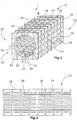
- eine perspektivische Ansicht einer achtteiligen Gitterstruktur-Entwässerungsvorrichtung.
- Fig. 1
- a perspective view of a first embodiment of a box-shaped dewatering device with four identical lattice structural parts,
- Fig. 2
- a plan view of one of the grid structure elements according to II of
Fig. 1 . - Fig. 3
- an alternative embodiment of a four-part grid structure with respect to the embodiment according to
Fig. 1 different Division and - Fig. 4
- a perspective view of an eight-part lattice structure dewatering device.
Die
Das zu versickernde Wasser wird über (nicht dargestellte) Abflussrohre in den Durchlass 20 geleitet, wo es über die Öffnungen 24 in die Gitteröffnungen 18 und deren Durchbrüche eindringt und schließlich sich über die gesamte Entwässerungsvorrichtung 10 verteilt. Mehrere Entwässerungsvorrichtungen gemäß
Der Vorteil der Herstellung der Entwässerungsvorrichtung 10 nach
In
In
Die Verbindung der Gitterstrukturteile 12 der zuvor beschriebenen Ausführungsbeispiele der Entwässerungsvorrichtung erfolgt vorzugsweise durch Verschweißen, Verkleben oder durch Verriegeln benachbarter Gitterstrukturteile mittels Rast- oder Verbindungselemente. Die Verbindungsstruktur muss so beschaffen sein, dass sie den statischen Lasten, die über das Erdreich auf die Entwässerungsvorrichtung einwirken, standhält.The connection of the
In den zuvor beschriebenen Figuren weisen die einzelnen Gitterstrukturteile 12 jeweils eine symmetrische Gitterstruktur auf. Es sei an dieser Stelle erwähnt, dass die Gitterstruktur zweckmäßigerweise auch asymmetrisch sein kann (bezogen auf eine in Längserstreckung verlaufende oder quer dazu verlaufende Symmetrieachse). Auch ist es möglich, bei geringeren im Einbauzustand zu erwartenden Belastungen die Gitterstrukturteile 12 der Figuren ihrerseits jeweils aus zwei gleichen Einzelteilen zusammenzusetzen, wie es in den
Zusätzlich kann eine Stützwand 26 in dem Durchlass 20 angeordnet sein, wie gezeigt ist. Die Stützwand 26 ist in diesem Ausführungsbeispiel mit Durchgangsaussparungen versehen, die sich als Öffnungen zwischen benachbarten Gitterstreben der Stützwand 26 bilden. Die Stützwand 26 stützt zwei gegenüberliegende Gitterstrukturteile 12 ab, wodurch die Stabilität der Entwässerungsvorrichtung 10 "' erhöht ist.In addition, a
Claims (6)
- A dewatering and/or drainage device comprising- a grid structure through which extends a passage (20) for the inlet of liquid to be drained,- wherein the grid structure is formed by at least three, preferably four identical parts (12) through which grid openings (18) extend, respectively, which, per part (12), all run from the inner side (22) of the passage (20) to the outer side of the grid structure, wherein each part (12) of the grid structure has a planar outer surface or two planar outer surfaces orthogonal to each other,characterized in- that the inner sides (22) of the parts (12) forming the passage (20) are either rounded and together form a continuous and rounded inner side (22) of the passage (20) or that the inner sides (22) of the parts (12) forming the passage (20) comprise, between each other, rounded lateral portions each contiguous with an adjacent part (12) and having a planar intermediate portion between the lateral portions and together form a continuous inner side (22) of the passage (20) having rounded portions defined by the rounded lateral portions of the parts (12) and planar portions defined by the intermediate portions of the parts (12).
- The dewatering and/or drainage device of claim 1, characterized in that the grid structure is formed from eight identical parts (12).
- The dewatering and/or drainage device of claim 1 or 2, characterized in that the assembled parts (12) define the passage (30) through the grid structure between them.
- The dewatering and/or drainage device of one of claims 1 to 3, characterized in that adjacent parts (12) are joined at their contact surfaces, in particular by glueing, welding or by means of connecting elements.
- The dewatering and/or drainage device of one of claims 1 to 4, characterized in that a supporting wall (26) extends in the passage (20) between two parts (12) of the grid structure, which supporting wall is supported at diametrically opposite portions of the two parts (12).
- The dewatering and/or drainage device of claim 5, characterized in that the supporting wall comprises passage openings.
Applications Claiming Priority (3)
| Application Number | Priority Date | Filing Date | Title |
|---|---|---|---|
| DE102006018171 | 2006-04-18 | ||
| DE102006027904 | 2006-06-17 | ||
| PCT/EP2007/053798 WO2007118894A1 (en) | 2006-04-18 | 2007-04-18 | Dewatering and/or drainage device |
Publications (2)
| Publication Number | Publication Date |
|---|---|
| EP2007949A1 EP2007949A1 (en) | 2008-12-31 |
| EP2007949B1 true EP2007949B1 (en) | 2017-03-15 |
Family
ID=38266748
Family Applications (1)
| Application Number | Title | Priority Date | Filing Date |
|---|---|---|---|
| EP07728260.6A Not-in-force EP2007949B1 (en) | 2006-04-18 | 2007-04-18 | Dewatering and/or drainage device |
Country Status (4)
| Country | Link |
|---|---|
| EP (1) | EP2007949B1 (en) |
| AU (1) | AU2007239489A1 (en) |
| DE (1) | DE112007000119A5 (en) |
| WO (1) | WO2007118894A1 (en) |
Families Citing this family (9)
| Publication number | Priority date | Publication date | Assignee | Title |
|---|---|---|---|---|
| EP1607534A1 (en) | 2004-06-18 | 2005-12-21 | Wavin B.V. | Infiltration block |
| DE102007058785B3 (en) * | 2007-12-06 | 2009-08-20 | Hewitech Gmbh & Co. Kg | Assembled dewatering or drainage device has identical, lattice-like side wall plates, which are arranged for forming cross sectional multiangular, particularly quadratic channels |
| GB2475551B (en) * | 2009-11-23 | 2012-12-26 | Polypipe Civils Ltd | Drainage cell |
| DE102011084022B3 (en) * | 2011-10-05 | 2013-03-07 | Hewitech Gmbh & Co. Kg | Installation for soil in the field of plants and methods of handling such installation |
| EP2754762A1 (en) | 2013-01-10 | 2014-07-16 | Hewitech GmbH & Co. KG | Drainage and/or fluid storage device for installation in the ground |
| DE102016106673B4 (en) | 2016-04-12 | 2019-04-25 | Hewitech Gmbh & Co. Kg | Apparatus for forming cavities in the ground for drainage and / or water storage purposes |
| DE202016101917U1 (en) | 2016-04-12 | 2017-07-13 | Hewitech Gmbh & Co. Kg | Apparatus for forming cavities in the ground for drainage and / or water storage purposes |
| WO2018083346A1 (en) | 2016-11-07 | 2018-05-11 | Hewitech Gmbh & Co. Kg | Device for forming trafficable hollow structures incorporated in the ground for drainage and/or water storage purposes |
| DE202019100340U1 (en) | 2019-01-22 | 2019-02-04 | Hewitech Gmbh & Co. Kg | Apparatus for forming cavities in the ground for drainage and / or water storage purposes |
Family Cites Families (6)
| Publication number | Priority date | Publication date | Assignee | Title |
|---|---|---|---|---|
| JP2617129B2 (en) * | 1989-02-23 | 1997-06-04 | 東急建設株式会社 | Construction method of underground infiltration equipment |
| DE29924050U1 (en) | 1998-03-18 | 2001-10-25 | Wavin Bv | Irrigation and / or drainage box |
| DE29923050U1 (en) | 1999-12-31 | 2000-03-30 | Lorenz Undine | String insert |
| DE10055327C1 (en) | 2000-11-08 | 2002-01-24 | Sendenhorst Kunststoffroehren | Grid plate for construction of 3-dimensional structure has struts within peripheral frame provided within variable spacing or cross-sectional geometry for increasing loading capacity at center of grid plate |
| EP1607534A1 (en) | 2004-06-18 | 2005-12-21 | Wavin B.V. | Infiltration block |
| DE202004018319U1 (en) | 2004-11-25 | 2005-04-28 | Heitker Gmbh | Modular drainage device for e.g. sports pitches or roads, comprises injection moulded single piece construction with integral frame and support parts |
-
2007
- 2007-04-18 AU AU2007239489A patent/AU2007239489A1/en not_active Abandoned
- 2007-04-18 EP EP07728260.6A patent/EP2007949B1/en not_active Not-in-force
- 2007-04-18 DE DE112007000119T patent/DE112007000119A5/en not_active Withdrawn
- 2007-04-18 WO PCT/EP2007/053798 patent/WO2007118894A1/en active Application Filing
Non-Patent Citations (1)
| Title |
|---|
| None * |
Also Published As
| Publication number | Publication date |
|---|---|
| DE112007000119A5 (en) | 2009-02-26 |
| WO2007118894A1 (en) | 2007-10-25 |
| AU2007239489A1 (en) | 2007-10-25 |
| EP2007949A1 (en) | 2008-12-31 |
Similar Documents
| Publication | Publication Date | Title |
|---|---|---|
| EP2007949B1 (en) | Dewatering and/or drainage device | |
| EP2470722B1 (en) | Drainage body | |
| DE60114178T2 (en) | STRUCTURAL MODULAR CONNECTABLE FLOOR DRAINAGE CELL | |
| EP2463449B1 (en) | Structure body for a trenching system and trenching system | |
| EP0371917A1 (en) | Capping frame for a drainage channel | |
| DE102010045001A1 (en) | Drainage system, process for its manufacture and components therefor | |
| DE102009004915A1 (en) | Rigolensystem with at least one Versickerbox | |
| EP3514310B1 (en) | Connector set for connecting a ground beam with a frame of a window or a door | |
| DE3631010C2 (en) | ||
| DE3935919C2 (en) | Support foot for raised floors | |
| EP2379817B1 (en) | Drainage device with several seepage boxes comprising a receptracle for a stabilizing element | |
| DE4002357C1 (en) | ||
| DE102007058785B3 (en) | Assembled dewatering or drainage device has identical, lattice-like side wall plates, which are arranged for forming cross sectional multiangular, particularly quadratic channels | |
| AT509154B1 (en) | SUCTION MODULE AND THE SUCKLING SYSTEM THEREFORE | |
| DE3025883C2 (en) | Precast retaining wall | |
| DE3041338A1 (en) | SIEVE BOTTOM | |
| AT508366B1 (en) | SUCTION MODULE AND THE SUCKLING SYSTEM THEREFORE | |
| DE2807692A1 (en) | CULTURAL TROUGH AND METHOD FOR THE PRODUCTION THEREOF | |
| DE202017106750U1 (en) | Device for the formation of drivable, for drainage and / or water storage purposes introduced into the ground cavities | |
| EP2492400A1 (en) | In-built unit | |
| DE19616622A1 (en) | Concrete form stone, kit of concrete form stones and a retaining wall made from it | |
| DE3510914A1 (en) | Double block | |
| DE4411648A1 (en) | Stackable transport container for transporting along roller tracks | |
| EP3443169A1 (en) | Device for forming cavities in the ground for water drainage and/or water storage | |
| DE8228747U1 (en) | RUST FOR THE WALK-ON COVERING OF GUTTERS, BASIN, PITS OR AS A DOOR-TO-DOOR |
Legal Events
| Date | Code | Title | Description |
|---|---|---|---|
| PUAI | Public reference made under article 153(3) epc to a published international application that has entered the european phase |
Free format text: ORIGINAL CODE: 0009012 |
|
| 17P | Request for examination filed |
Effective date: 20080702 |
|
| AK | Designated contracting states |
Kind code of ref document: A1 Designated state(s): AT BE BG CH CY CZ DE DK EE ES FI FR GB GR HU IE IS IT LI LT LU LV MC MT NL PL PT RO SE SI SK TR |
|
| AX | Request for extension of the european patent |
Extension state: AL BA HR MK RS |
|
| DAX | Request for extension of the european patent (deleted) | ||
| 17Q | First examination report despatched |
Effective date: 20150319 |
|
| GRAP | Despatch of communication of intention to grant a patent |
Free format text: ORIGINAL CODE: EPIDOSNIGR1 |
|
| INTG | Intention to grant announced |
Effective date: 20161006 |
|
| GRAS | Grant fee paid |
Free format text: ORIGINAL CODE: EPIDOSNIGR3 |
|
| GRAA | (expected) grant |
Free format text: ORIGINAL CODE: 0009210 |
|
| AK | Designated contracting states |
Kind code of ref document: B1 Designated state(s): AT BE BG CH CY CZ DE DK EE ES FI FR GB GR HU IE IS IT LI LT LU LV MC MT NL PL PT RO SE SI SK TR |
|
| REG | Reference to a national code |
Ref country code: CH Ref legal event code: EP Ref country code: GB Ref legal event code: FG4D Free format text: NOT ENGLISH |
|
| REG | Reference to a national code |
Ref country code: IE Ref legal event code: FG4D Free format text: LANGUAGE OF EP DOCUMENT: GERMAN |
|
| REG | Reference to a national code |
Ref country code: AT Ref legal event code: REF Ref document number: 875715 Country of ref document: AT Kind code of ref document: T Effective date: 20170415 |
|
| REG | Reference to a national code |
Ref country code: DE Ref legal event code: R096 Ref document number: 502007015513 Country of ref document: DE |
|
| REG | Reference to a national code |
Ref country code: NL Ref legal event code: MP Effective date: 20170315 |
|
| REG | Reference to a national code |
Ref country code: LT Ref legal event code: MG4D |
|
| PG25 | Lapsed in a contracting state [announced via postgrant information from national office to epo] |
Ref country code: FI Free format text: LAPSE BECAUSE OF FAILURE TO SUBMIT A TRANSLATION OF THE DESCRIPTION OR TO PAY THE FEE WITHIN THE PRESCRIBED TIME-LIMIT Effective date: 20170315 Ref country code: LT Free format text: LAPSE BECAUSE OF FAILURE TO SUBMIT A TRANSLATION OF THE DESCRIPTION OR TO PAY THE FEE WITHIN THE PRESCRIBED TIME-LIMIT Effective date: 20170315 Ref country code: GR Free format text: LAPSE BECAUSE OF FAILURE TO SUBMIT A TRANSLATION OF THE DESCRIPTION OR TO PAY THE FEE WITHIN THE PRESCRIBED TIME-LIMIT Effective date: 20170616 |
|
| PG25 | Lapsed in a contracting state [announced via postgrant information from national office to epo] |
Ref country code: BG Free format text: LAPSE BECAUSE OF FAILURE TO SUBMIT A TRANSLATION OF THE DESCRIPTION OR TO PAY THE FEE WITHIN THE PRESCRIBED TIME-LIMIT Effective date: 20170615 Ref country code: LV Free format text: LAPSE BECAUSE OF FAILURE TO SUBMIT A TRANSLATION OF THE DESCRIPTION OR TO PAY THE FEE WITHIN THE PRESCRIBED TIME-LIMIT Effective date: 20170315 Ref country code: SE Free format text: LAPSE BECAUSE OF FAILURE TO SUBMIT A TRANSLATION OF THE DESCRIPTION OR TO PAY THE FEE WITHIN THE PRESCRIBED TIME-LIMIT Effective date: 20170315 |
|
| PG25 | Lapsed in a contracting state [announced via postgrant information from national office to epo] |
Ref country code: NL Free format text: LAPSE BECAUSE OF FAILURE TO SUBMIT A TRANSLATION OF THE DESCRIPTION OR TO PAY THE FEE WITHIN THE PRESCRIBED TIME-LIMIT Effective date: 20170315 |
|
| PG25 | Lapsed in a contracting state [announced via postgrant information from national office to epo] |
Ref country code: IT Free format text: LAPSE BECAUSE OF FAILURE TO SUBMIT A TRANSLATION OF THE DESCRIPTION OR TO PAY THE FEE WITHIN THE PRESCRIBED TIME-LIMIT Effective date: 20170315 Ref country code: RO Free format text: LAPSE BECAUSE OF FAILURE TO SUBMIT A TRANSLATION OF THE DESCRIPTION OR TO PAY THE FEE WITHIN THE PRESCRIBED TIME-LIMIT Effective date: 20170315 Ref country code: CZ Free format text: LAPSE BECAUSE OF FAILURE TO SUBMIT A TRANSLATION OF THE DESCRIPTION OR TO PAY THE FEE WITHIN THE PRESCRIBED TIME-LIMIT Effective date: 20170315 Ref country code: EE Free format text: LAPSE BECAUSE OF FAILURE TO SUBMIT A TRANSLATION OF THE DESCRIPTION OR TO PAY THE FEE WITHIN THE PRESCRIBED TIME-LIMIT Effective date: 20170315 Ref country code: SK Free format text: LAPSE BECAUSE OF FAILURE TO SUBMIT A TRANSLATION OF THE DESCRIPTION OR TO PAY THE FEE WITHIN THE PRESCRIBED TIME-LIMIT Effective date: 20170315 Ref country code: ES Free format text: LAPSE BECAUSE OF FAILURE TO SUBMIT A TRANSLATION OF THE DESCRIPTION OR TO PAY THE FEE WITHIN THE PRESCRIBED TIME-LIMIT Effective date: 20170315 |
|
| PG25 | Lapsed in a contracting state [announced via postgrant information from national office to epo] |
Ref country code: PT Free format text: LAPSE BECAUSE OF FAILURE TO SUBMIT A TRANSLATION OF THE DESCRIPTION OR TO PAY THE FEE WITHIN THE PRESCRIBED TIME-LIMIT Effective date: 20170717 Ref country code: IS Free format text: LAPSE BECAUSE OF FAILURE TO SUBMIT A TRANSLATION OF THE DESCRIPTION OR TO PAY THE FEE WITHIN THE PRESCRIBED TIME-LIMIT Effective date: 20170715 Ref country code: PL Free format text: LAPSE BECAUSE OF FAILURE TO SUBMIT A TRANSLATION OF THE DESCRIPTION OR TO PAY THE FEE WITHIN THE PRESCRIBED TIME-LIMIT Effective date: 20170315 |
|
| REG | Reference to a national code |
Ref country code: CH Ref legal event code: PL |
|
| REG | Reference to a national code |
Ref country code: DE Ref legal event code: R097 Ref document number: 502007015513 Country of ref document: DE |
|
| PLBE | No opposition filed within time limit |
Free format text: ORIGINAL CODE: 0009261 |
|
| STAA | Information on the status of an ep patent application or granted ep patent |
Free format text: STATUS: NO OPPOSITION FILED WITHIN TIME LIMIT |
|
| REG | Reference to a national code |
Ref country code: IE Ref legal event code: MM4A |
|
| REG | Reference to a national code |
Ref country code: FR Ref legal event code: ST Effective date: 20171229 |
|
| PG25 | Lapsed in a contracting state [announced via postgrant information from national office to epo] |
Ref country code: MC Free format text: LAPSE BECAUSE OF FAILURE TO SUBMIT A TRANSLATION OF THE DESCRIPTION OR TO PAY THE FEE WITHIN THE PRESCRIBED TIME-LIMIT Effective date: 20170315 Ref country code: FR Free format text: LAPSE BECAUSE OF NON-PAYMENT OF DUE FEES Effective date: 20170515 Ref country code: DK Free format text: LAPSE BECAUSE OF FAILURE TO SUBMIT A TRANSLATION OF THE DESCRIPTION OR TO PAY THE FEE WITHIN THE PRESCRIBED TIME-LIMIT Effective date: 20170315 |
|
| 26N | No opposition filed |
Effective date: 20171218 |
|
| GBPC | Gb: european patent ceased through non-payment of renewal fee |
Effective date: 20170615 |
|
| PG25 | Lapsed in a contracting state [announced via postgrant information from national office to epo] |
Ref country code: LI Free format text: LAPSE BECAUSE OF NON-PAYMENT OF DUE FEES Effective date: 20170430 Ref country code: CH Free format text: LAPSE BECAUSE OF NON-PAYMENT OF DUE FEES Effective date: 20170430 Ref country code: LU Free format text: LAPSE BECAUSE OF NON-PAYMENT OF DUE FEES Effective date: 20170418 Ref country code: SI Free format text: LAPSE BECAUSE OF FAILURE TO SUBMIT A TRANSLATION OF THE DESCRIPTION OR TO PAY THE FEE WITHIN THE PRESCRIBED TIME-LIMIT Effective date: 20170315 |
|
| REG | Reference to a national code |
Ref country code: BE Ref legal event code: MM Effective date: 20170430 |
|
| PG25 | Lapsed in a contracting state [announced via postgrant information from national office to epo] |
Ref country code: GB Free format text: LAPSE BECAUSE OF NON-PAYMENT OF DUE FEES Effective date: 20170615 Ref country code: IE Free format text: LAPSE BECAUSE OF NON-PAYMENT OF DUE FEES Effective date: 20170418 |
|
| PG25 | Lapsed in a contracting state [announced via postgrant information from national office to epo] |
Ref country code: BE Free format text: LAPSE BECAUSE OF NON-PAYMENT OF DUE FEES Effective date: 20170430 |
|
| REG | Reference to a national code |
Ref country code: AT Ref legal event code: MM01 Ref document number: 875715 Country of ref document: AT Kind code of ref document: T Effective date: 20170418 |
|
| PG25 | Lapsed in a contracting state [announced via postgrant information from national office to epo] |
Ref country code: AT Free format text: LAPSE BECAUSE OF NON-PAYMENT OF DUE FEES Effective date: 20170418 |
|
| PG25 | Lapsed in a contracting state [announced via postgrant information from national office to epo] |
Ref country code: MT Free format text: LAPSE BECAUSE OF FAILURE TO SUBMIT A TRANSLATION OF THE DESCRIPTION OR TO PAY THE FEE WITHIN THE PRESCRIBED TIME-LIMIT Effective date: 20170315 |
|
| PG25 | Lapsed in a contracting state [announced via postgrant information from national office to epo] |
Ref country code: HU Free format text: LAPSE BECAUSE OF FAILURE TO SUBMIT A TRANSLATION OF THE DESCRIPTION OR TO PAY THE FEE WITHIN THE PRESCRIBED TIME-LIMIT; INVALID AB INITIO Effective date: 20070418 |
|
| PGFP | Annual fee paid to national office [announced via postgrant information from national office to epo] |
Ref country code: DE Payment date: 20190430 Year of fee payment: 13 |
|
| PG25 | Lapsed in a contracting state [announced via postgrant information from national office to epo] |
Ref country code: CY Free format text: LAPSE BECAUSE OF NON-PAYMENT OF DUE FEES Effective date: 20170315 |
|
| PG25 | Lapsed in a contracting state [announced via postgrant information from national office to epo] |
Ref country code: TR Free format text: LAPSE BECAUSE OF FAILURE TO SUBMIT A TRANSLATION OF THE DESCRIPTION OR TO PAY THE FEE WITHIN THE PRESCRIBED TIME-LIMIT Effective date: 20170315 |
|
| REG | Reference to a national code |
Ref country code: DE Ref legal event code: R119 Ref document number: 502007015513 Country of ref document: DE |
|
| PG25 | Lapsed in a contracting state [announced via postgrant information from national office to epo] |
Ref country code: DE Free format text: LAPSE BECAUSE OF NON-PAYMENT OF DUE FEES Effective date: 20201103 |