EP2007583B1 - Cleaning system for a printing press - Google Patents
Cleaning system for a printing press Download PDFInfo
- Publication number
- EP2007583B1 EP2007583B1 EP06750755.8A EP06750755A EP2007583B1 EP 2007583 B1 EP2007583 B1 EP 2007583B1 EP 06750755 A EP06750755 A EP 06750755A EP 2007583 B1 EP2007583 B1 EP 2007583B1
- Authority
- EP
- European Patent Office
- Prior art keywords
- color
- cleaning
- ink
- tank
- printing press
- Prior art date
- Legal status (The legal status is an assumption and is not a legal conclusion. Google has not performed a legal analysis and makes no representation as to the accuracy of the status listed.)
- Ceased
Links
- 238000004140 cleaning Methods 0.000 title claims description 125
- 238000007639 printing Methods 0.000 title claims description 71
- 239000012530 fluid Substances 0.000 claims description 58
- 238000000034 method Methods 0.000 claims description 49
- 239000003086 colorant Substances 0.000 claims description 13
- 238000009434 installation Methods 0.000 claims description 2
- 238000001914 filtration Methods 0.000 claims 1
- 239000000976 ink Substances 0.000 description 70
- 238000010586 diagram Methods 0.000 description 6
- 238000001816 cooling Methods 0.000 description 4
- 238000010438 heat treatment Methods 0.000 description 4
- 238000005086 pumping Methods 0.000 description 3
- 230000008901 benefit Effects 0.000 description 2
- 238000003384 imaging method Methods 0.000 description 2
- 238000003780 insertion Methods 0.000 description 2
- 230000037431 insertion Effects 0.000 description 2
- 239000007788 liquid Substances 0.000 description 2
- 238000007789 sealing Methods 0.000 description 2
- 230000003466 anti-cipated effect Effects 0.000 description 1
- 230000000694 effects Effects 0.000 description 1
- 238000000605 extraction Methods 0.000 description 1
- 230000005484 gravity Effects 0.000 description 1
- 238000007646 gravure printing Methods 0.000 description 1
- 239000012535 impurity Substances 0.000 description 1
- 238000004519 manufacturing process Methods 0.000 description 1
- 238000005259 measurement Methods 0.000 description 1
- 238000007645 offset printing Methods 0.000 description 1
- 230000003287 optical effect Effects 0.000 description 1
- 239000004065 semiconductor Substances 0.000 description 1
- 239000007921 spray Substances 0.000 description 1
- 238000005507 spraying Methods 0.000 description 1
- 239000000725 suspension Substances 0.000 description 1
Images


Classifications
-
- B—PERFORMING OPERATIONS; TRANSPORTING
- B41—PRINTING; LINING MACHINES; TYPEWRITERS; STAMPS
- B41F—PRINTING MACHINES OR PRESSES
- B41F35/00—Cleaning arrangements or devices
-
- B—PERFORMING OPERATIONS; TRANSPORTING
- B41—PRINTING; LINING MACHINES; TYPEWRITERS; STAMPS
- B41L—APPARATUS OR DEVICES FOR MANIFOLDING, DUPLICATING OR PRINTING FOR OFFICE OR OTHER COMMERCIAL PURPOSES; ADDRESSING MACHINES OR LIKE SERIES-PRINTING MACHINES
- B41L41/00—Cleaning arrangements or devices
-
- B—PERFORMING OPERATIONS; TRANSPORTING
- B41—PRINTING; LINING MACHINES; TYPEWRITERS; STAMPS
- B41P—INDEXING SCHEME RELATING TO PRINTING, LINING MACHINES, TYPEWRITERS, AND TO STAMPS
- B41P2235/00—Cleaning
- B41P2235/30—Recovering used solvents or residues
- B41P2235/31—Recovering used solvents or residues by filtering
Definitions
- the inks and/or ink colors required for all print jobs are not the same.
- many print jobs can benefit from the addition of one or more 'specialty ink colors,' (e.g. spot colors) which improves the print job's appearance, but which may have little utility in other print jobs.
- 'specialty ink colors e.g. spot colors
- This value can be realized by removing an unneeded color and installing the needed color.
- Unfortunately there is also a cost associated with making this reconfiguration.
- Part of the cost of configuring a printer or printing press to use one or more specialty colors includes costs associated with temporary suspension of printing operations to allow for reconfiguration of a color station with a new ink color. While the printer or press is stopped, ink supply structures associated with one or more of the currently installed ink colors are removed. A cleaning apparatus is attached to the printer or press, and developing units and tubes are cleaned. A new ink color supply is installed, and building and calibration processes are performed on the newly installed ink color.
- WO98/42511 discloses a pumping unit for supplying printing ink to a printing unit.
- the described pumping unit is arranged with a printing ink tank and a cleaning liquid tank.
- the pipe for sucking up or return pumping of the cleaning liquid/printing ink may be slided from a position in one or the other tank. Process steps of inking as well as of cleaning are controlled by a central control unit so that the only intervention of the operator that is necessary, is exchange of the printing ink tank when a new printing ink colour is to be applied in the printing unit.
- DE-A-4338625 disloses a method for automatically cleaning the inking system of an offset printing equipment.
- An ink reservoir is secured with a sealed cover and cleaning fluid is pumped in from a reservoir.
- Removed ink and cleaning fluid drains into a collecting tank.
- Cleaning fluid is sprayed over the inking train while the inking pressure roller is cleaned by a scraper, with the removed ink and cleaning fluid drained into the collecting tank.
- the cleaning fluid can be warmed for enhanced cleaning effect, and is spread over the roller train by the roller action during the cleaning cycle.
- the collected ink and fluid are separated to allow reuse of the cleaning fluid.
- AT-B-407134 teaches a cleaning system for fully automatic cleaning of the impression cylinders of, preferably, flexo printing machines and gravure printing machines. The cleaning is to be carried out during the printing operation and without interrupting production.
- a housing opening forms a tight and closed unit with the impression cylinder, the part of the housing of the cleaning device which is open towards the impression cylinder having the same circular geometry has the shape of the outer surface of the impression cylinder.
- the length of the housing in the axial direction is identical to the length of the impression cylinder and, in the interior of the housing, there are arranged a spraying device, a rotating brush, an extraction device, a spray protection plate, and two compressed-air sealing strips. Sliding sealing elements are arranged at the housing opening.
- a method, at least partially implemented by means of processor-executable instructions, for exchanging colors within a color station of a printing press is disclosed.
- a cleaning tank is operated within the color station, thereby cleaning the color station. Additionally, a new color of ink is built within the cleaned color station.
- Fig. 1 illustrates one example of a printing press adapted according to the description disclosed herein.
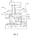
- Fig. 2 illustrates a block diagram showing an example of a cleaning tank interfaced to a printing press.
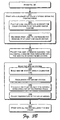
- Figs. 3A and 3B illustrate an example by which a printing press cleaning system can be operated.
- Fig. 1 illustrates one example of a printing press 100 adapted according to the description disclosed herein.
- the cleaning system includes a cleaning tank, adapted for insertion into a color station within the printing press 100.
- the cleaning system also includes a control procedure resident within the printing press 100 and discussed more fully in Figs. 3A and 3B .
- the control procedure controls the operation of a cleaning process including operation of the cleaning tank, and controls the operation of a building process wherein a new color is configured after the cleaning process is completed.
- the control procedure prints jobs by operating color stations not being cleaned while the cleaning and new color building processes in progress.
- each color station 102 includes both fixed and removable components.
- the fixed components include tubes and a developing unit (discussed with respect to Fig. 2 ), which are cleaned without removal from the printing press 100.
- the removable components include an ink tank 104 and an ink can 106. In an alternate embodiment, these removable components may be combined.
- each color station 102 may include other removable components that, when exchanged, replenish an exhausted ink supply.
- the ink tank 104 and ink can 106 are configured for manual insertion into, and removal from, a 'receiver' or 'socket' 108.
- the receiver 108 interfaces with the ink tank 104 and ink can 106, thereby allowing the press 100 to control the operation of the ink tank and ink can.
- the press 100 controls the application of ink from the ink tank 104 and ink can 106 onto a developing unit, and from there onto print media.
- Fig. 2 illustrates a block diagram showing an example of a cleaning tank 200 interface to the receiver 108 of a color station 102 ( Fig. 1 ) of a printing press 100 ( Fig. 1 ).
- the cleaning tank 200 provides cleaning fluid to the developing unit 202, wherein the developing unit is a portion of the color station 102 ( Fig. 1 ) that is typically fixed in an internal location within the printing press 100.
- the printing press 100 ( Fig. 1 ) provides instructions to the cleaning tank 200, resulting in circulation of cleaning fluid to the developing unit 202, tubes, pipes and other structures within a color station 102 ( Fig. 1 ).
- the press 100 or cleaning tank 200 heats and/or controls the temperature of the cleaning fluid to maximize cleaning process efficiency.
- additional instructions to other color stations result in the continued work on print jobs.
- the cleaning tank 200 includes a fluid reservoir 204 containing cleaning fluid 206, a pump 208 to circulate the cleaning fluid, a filter 210 to remove ink and/or impurities from the cleaning fluid, and a circuit card 212 to interface with the printing press 100 ( Fig. 1 ) and to thereby allow the press to control operation of the cleaning tank 200.
- the reservoir 204 is typically configured according to a form factor that allows it to fit into the receiver 108 after removal of the ink tank 104 and ink can 106 ( Fig. 1 ). Accordingly, an operator can manually remove the ink tank 104 and ink can 106 of a color station 102 (all seem in Fig. 1 ). Once removed, the user can manually insert the cleaning tank 200 within the color station 102.
- the reservoir 204 contains sufficient cleaning fluid 206 to clean the one color station without replacement of the cleaning tank 200.
- the cleaning fluid used is known as "imaging oil"; however, it is anticipated that any known cleaning fluid could be used, as desired.
- the pump 208 includes an intake port 214, which receives cleaning fluid 206 from within the reservoir 204.
- the pump 208 releases the cleaning fluid under some pressure through supply line 216.
- the supply line 216 delivers cleaning fluid 206 to a filter intake port 218 and a developing unit input line 220.
- filtered cleaning fluid is returned to the fluid reservoir 204 via an exhaust port 222.
- Cleaning fluid passing through the developing unit input line 220 cleans ink and/or debris from the developing unit 202 before returning to the reservoir 204 via a return line 224.
- the circuit card 212 interfaces with the printing press 100 ( Fig. 1 ). Accordingly, a control procedure-typically configured as software-is able to control operation of the cleaning tank 200. In particular, the control procedure within the printing press controls operation of the pump 208. In a typical implementation, the control procedure operates the pump at a speed, and for a period of time, that is consistent with the task of cleaning the developing unit 202 and other portions of the color station 102 ( Fig. 1 ). In a typical implementation, the circuit card 212 also controls the temperature of the cleaning fluid. A thermometer, typically in contact with the cleaning fluid 206, provides feedback to the circuit card 212. This information can be used to operate the heating (and/or cooling) tube 234.
- the control procedure resident within the printing press 100 measures the time of operation of the operation of the cleaning tank 200 generally, and the pump 208 in particular.
- the pump 208 can be controlled by the circuit card 212, such as by operation of a signal or power line 228.
- a motor 238 and drive shaft 240 may also be controlled by the circuit card 212, and configured to operate the pump 208.
- the circuit card 212 can be controlled by a control procedure resident on the printing press 100, via electrical connections 230, 232.
- connector 230 is configured to interface with the connector 232 of the circuit card 212, as well as the ink tank 106 and/or ink can 108 of the color station.
- the control procedure resident within the printing press can receive input data from an optional densitometer 226 on the circuit card 212.
- the densitometer 226 is representative of any of a plurality of sensors adapted to examine cleaning fluid, and to track progress in the cleaning task. In operation, the densitometer 226 measures density of the cleaning fluid 206, and thereby determines if ink is still being removed from the developing unit 202.
- the control procedure can gain information on the state of the cleaning process. For example, when the density of the cleaning fluid indicates that the cleaning fluid is 'clean,' i.e. free of ink and debris, then the control procedure can assume that the developing unit 202 and other portions of the color station 102 are clean.
- the cleaning process may be controlled by either timed operation of the pump 208, by reference to a sensor such as the densitometer 226, or by a combination of both.
- the densitometer 226 can detect problems in the cleaning procedure. For example, failure of the density of the cleaning fluid to decrease may indicate that there is a problem in the filter.
- a heating/cooling tube 234 inside the reservoir 204 controls the temperature of the fluid 206.
- the tube 234 can be connected to the receiver 108 using a quick connection 236.
- the heating/cooling tube 234 provides control over the temperature of the cleaning fluid, which increases the efficiency of the cleaning process. Accordingly, the cleaning fluid may be maintained at a desired temperature while circulating within the color station.
- the pump 208 pumps the cleaning fluid in two 'parallel circuits,' wherein a first portion of the cleaning fluid is pumped through the developing unit 202 of a color station 102 and a second portion of the cleaning fluid is pumped through the filter 210.
- the filter 210 could be 'in series' with the developing unit; i.e. fluid could leave the pump 208, pass through the filter 210, then pass through the developing unit 102, before returning to the fluid reservoir 204.
- this configuration is less satisfactory, since the pressure drop across the filter is difficult to predict with precision.
- An alternative configuration, wherein the cleaning fluid leaving the pump passes through the developing unit first, and then passes through the filter is also less satisfactory in many applications, since fluid leaving the developing unit is typically gravity-fed back to the reservoir 204, and has insufficient pressure to pass through the filter.
- Figs. 3A and 3B disclose an examples method 300 by which a printing press cleaning system can be implemented and operated, and by which a color replacement may be performed.
- the method will be associated with the printing press 100, as seen in Fig. 1 and the cleaning tank 200, as seen in Fig. 2 .
- the engineer trained in printing press design will realize that the teachings of the discussions herein could be adapted for alternative implementations, as desired.
- an example software control procedure 302 configured for operation by the printing press 100 ( Fig. 1 ), implements aspects of a printing press cleaning system. That control procedure 302 will now be described with primary reference to the flow diagrams of Figs. 3A and 3B , and secondary reference to the example structures of Figs. 1 and 2 .
- the methods 300 apply to a wide variety or printing presses generally and in particular to the operation of exemplary components discussed above with respect to Figs. 1 and 2 .
- the control procedure 302 is configured as software, the elements of the described methods may be performed by any appropriate means including, for example, software, including execution of processor-readable instructions defined on a processor-readable medium, or hardware, including logic blocks on an ASIC or other electronic device.
- a computer and/or processor-readable medium can be any means that can contain or store instructions for use by or execution by a processor.
- a processor-readable medium can be, without limitation, an electronic, magnetic, optical, electromagnetic, infrared, or semiconductor system, apparatus, device, or propagation medium. More specific examples of a processor-readable medium include, among others, a portable computer diskette, a random access memory (RAM), a read-only memory (ROM), an erasable programmable-read-only memory (EPROM or Flash memory), a rewritable compact disc (CD-RW), and a portable compact disc read-only memory (CDROM).
- RAM random access memory
- ROM read-only memory
- EPROM or Flash memory erasable programmable-read-only memory
- CD-RW rewritable compact disc
- CDROM portable compact disc read-only memory
- a user interface is provided by the printing press 100 ( Fig. 1 ), allowing the user to issue commands to the control procedure and/or printing press, and to be prompted by the control procedure to perform tasks which must be performed manually.
- Blocks 306-310 illustrate possible examples of operation of the user interface.
- the user interface allows a user to request replacement of a color within a color station of the printing press. The user may indicate the color station wherein the replacement is to take place, the ink color to be removed (i.e. the currently installed ink color) and the ink color to be installed.
- the user interface instructs (i.e.
- the user interface prompts the user to install the cleaning tank 200 into the color station 102 of the printing press 100 wherein the color replacement is being performed.
- the form factor of the cleaning tank 200 is similar enough to the ink tank 104 and ink can 106 that the cleaning tank can be inserted into the color station 102.
- the cleaning tank is operated, thereby cleaning the color station within which the cleaning tank is installed.
- Blocks 314-320 illustrate possible examples of operation of cleaning tank.
- cleaning fluid is circulated and filtered.
- the cleaning fluid may be heated and/or cooled as needed, such as by heating/cooling rod 234 ( Fig. 2 ).
- operation of a pump is controlled, wherein the pump actively circulates cleaning fluid through a developing unit and associated tube, pipes, valves, etc., within the printing press.
- passage of cleaning fluid through the developing unit 202 cleans ink and debris from the unit, as well as pipes 220 and 224.
- the fluid is pumped in two parallel circuits.
- the pump circulates cleaning fluid through the developing unit 202 and the filter 210 in a 'parallel' manner, rather than in 'series'.
- the pump 208 circulates cleaning fluid through the filter 210, which removes ink and debris from the cleaning fluid.
- the pump also circulates fluid through the developing unit 202, thereby cleaning the color station 102.
- the operation of the pump 208 can be controlled by the control procedure 302 by reference to a timer or clock.
- the control procedure 302 may reference a densitometer 226, or similar sensing device, to determine the state of the cleaning fluid. For example, if the device reports that the fluid is generally clean, then the developing unit 202 and/or other parts of the color station 102 can be considered clean.
- a plurality of color stations are used in the printing process. That is, while the cleaning steps of blocks 312-320 are in operation, and while the new ink station building blocks 330-338 are in operation, other color stations may be simultaneously involved in actively performing print jobs.
- Blocks 324 and 326 refine and/or clarify the process by which cleaning and printing are simultaneously performed.
- all colors stations are used except the color station(s) being cleaned and/or replaced by a newly built ink station. That is, the control procedure 302 operating the printing press 100 is configured to operate and print using the printing press without the color station undergoing cleaning.
- the control procedure 302 may be configured to reorder print jobs so that print job(s) printed during cleaning may be performed without the color station being cleaned.
- a print queue having print jobs will be reordered to move print jobs not requiring the color removed at block 308 to earlier positions in the print queue, and to move print jobs requiring a new color to be built at blocks 330-338 to later positions in the print queue.
- the user is prompted to remove the cleaning tank and to install a new ink tank (and ink can, depending on the configuration of the printing press) associated with the new color within the ink station.
- the prompting is typically made to the user by means of a user interface of any type.
- the removals and the installation are typically performed manually by the user.
- the new ink station is built. While building can vary from printing press to printing press, blocks 332-336 provide example detail on the building process.
- the new ink tank 104 contains imaging oil and a calibration can or container that contains a specific amount of ink. Accordingly, ink fluid of a known density will be introduced into the press 100 after the can containing the specific amount of ink is emptied into the ink tank by the press.
- the new ink tank is recalibrated.
- ink from the new ink tank and/or can is circulated into the developing unit 202 ( Fig. 2 ) of the printing press 100 ( Fig. 1 ).
- the temperature of the ink is adjusted.
- the printing press 100 resumes printing with all color stations, including the newly cleaned and newly built color station.
Landscapes
- Inking, Control Or Cleaning Of Printing Machines (AREA)
- Ink Jet (AREA)
Description
- The inks and/or ink colors required for all print jobs are not the same. For example, many print jobs can benefit from the addition of one or more 'specialty ink colors,' (e.g. spot colors) which improves the print job's appearance, but which may have little utility in other print jobs. Thus, there is a value in configuring a printer and/or printing press to utilize specialty colors for some printing jobs. This value can be realized by removing an unneeded color and installing the needed color. Unfortunately, there is also a cost associated with making this reconfiguration.
- Part of the cost of configuring a printer or printing press to use one or more specialty colors includes costs associated with temporary suspension of printing operations to allow for reconfiguration of a color station with a new ink color. While the printer or press is stopped, ink supply structures associated with one or more of the currently installed ink colors are removed. A cleaning apparatus is attached to the printer or press, and developing units and tubes are cleaned. A new ink color supply is installed, and building and calibration processes are performed on the newly installed ink color.
- An additional cost typically results when the specialty color is removed, and replaced with a further specialty color or a standard color. Once again, the printing press must be stopped, and cleaning and color building operations performed. Thus, time during which the printing press is non-operational contributes to the costs of operation.
-
WO98/42511 -
DE-A-4338625 disloses a method for automatically cleaning the inking system of an offset printing equipment. An ink reservoir is secured with a sealed cover and cleaning fluid is pumped in from a reservoir. Removed ink and cleaning fluid drains into a collecting tank. Cleaning fluid is sprayed over the inking train while the inking pressure roller is cleaned by a scraper, with the removed ink and cleaning fluid drained into the collecting tank. The cleaning fluid can be warmed for enhanced cleaning effect, and is spread over the roller train by the roller action during the cleaning cycle. The collected ink and fluid are separated to allow reuse of the cleaning fluid. -
AT-B-407134 - A method, at least partially implemented by means of processor-executable instructions, for exchanging colors within a color station of a printing press is disclosed. In one implementation of the method, a cleaning tank is operated within the color station, thereby cleaning the color station. Additionally, a new color of ink is built within the cleaned color station.
- This Summary is provided to introduce a selection of concepts in a simplified form that are further described below in the Detailed Description. This Summary is not intended to identify key features or essential features of the claimed subject matter, nor is it intended for use as an aid in determining the scope of the claimed subject matter.
- The detailed description is described with reference to the accompanying figures. In the figures, the left-most digit(s) of a reference numbers identifies the figure in which the reference number first appears. The use of the same reference numbers in different figures indicates similar or identical items.
-
Fig. 1 illustrates one example of a printing press adapted according to the description disclosed herein. -
Fig. 2 illustrates a block diagram showing an example of a cleaning tank interfaced to a printing press. -
Figs. 3A and3B illustrate an example by which a printing press cleaning system can be operated. - The following discussion is directed to systems and methods that implement a cleaning system for use with a printing press.
Fig. 1 illustrates one example of aprinting press 100 adapted according to the description disclosed herein. The cleaning system includes a cleaning tank, adapted for insertion into a color station within theprinting press 100. The cleaning system also includes a control procedure resident within theprinting press 100 and discussed more fully inFigs. 3A and3B . In operation, the control procedure controls the operation of a cleaning process including operation of the cleaning tank, and controls the operation of a building process wherein a new color is configured after the cleaning process is completed. In a typical implementation, the control procedure prints jobs by operating color stations not being cleaned while the cleaning and new color building processes in progress. - Continuing to refer to
Fig. 1 , theexample printing press 100 includes sevencolor stations 102; however, thepress 100 could be configured with a greater or lesser number of color stations, as required by any particular implementation. In the example ofFig. 1 , eachcolor station 102 includes both fixed and removable components. The fixed components include tubes and a developing unit (discussed with respect toFig. 2 ), which are cleaned without removal from theprinting press 100. The removable components include anink tank 104 and an ink can 106. In an alternate embodiment, these removable components may be combined. In a still further embodiment, eachcolor station 102 may include other removable components that, when exchanged, replenish an exhausted ink supply. - The
ink tank 104 and ink can 106 are configured for manual insertion into, and removal from, a 'receiver' or 'socket' 108. Thereceiver 108 interfaces with theink tank 104 and ink can 106, thereby allowing thepress 100 to control the operation of the ink tank and ink can. In particular, thepress 100 controls the application of ink from theink tank 104 and ink can 106 onto a developing unit, and from there onto print media. -
Fig. 2 illustrates a block diagram showing an example of acleaning tank 200 interface to thereceiver 108 of a color station 102 (Fig. 1 ) of a printing press 100 (Fig. 1 ). In operation, thecleaning tank 200 provides cleaning fluid to the developingunit 202, wherein the developing unit is a portion of the color station 102 (Fig. 1 ) that is typically fixed in an internal location within theprinting press 100. More particularly, the printing press 100 (Fig. 1 ) provides instructions to thecleaning tank 200, resulting in circulation of cleaning fluid to the developingunit 202, tubes, pipes and other structures within a color station 102 (Fig. 1 ). In a preferred implementation, thepress 100 orcleaning tank 200 heats and/or controls the temperature of the cleaning fluid to maximize cleaning process efficiency. During the cleaning process, wherein instructions are provided to operates thecleaning tank 200, additional instructions to other color stations result in the continued work on print jobs. - In the example of
Fig. 2 , thecleaning tank 200 includes afluid reservoir 204 containingcleaning fluid 206, apump 208 to circulate the cleaning fluid, afilter 210 to remove ink and/or impurities from the cleaning fluid, and acircuit card 212 to interface with the printing press 100 (Fig. 1 ) and to thereby allow the press to control operation of thecleaning tank 200. - The
reservoir 204 is typically configured according to a form factor that allows it to fit into thereceiver 108 after removal of theink tank 104 and ink can 106 (Fig. 1 ). Accordingly, an operator can manually remove theink tank 104 and ink can 106 of a color station 102 (all seem inFig. 1 ). Once removed, the user can manually insert thecleaning tank 200 within thecolor station 102. In a preferred embodiment, thereservoir 204 containssufficient cleaning fluid 206 to clean the one color station without replacement of thecleaning tank 200. In one example, the cleaning fluid used is known as "imaging oil"; however, it is anticipated that any known cleaning fluid could be used, as desired. - Continuing to refer to
Fig. 2 , thepump 208 includes anintake port 214, which receives cleaning fluid 206 from within thereservoir 204. Thepump 208 releases the cleaning fluid under some pressure throughsupply line 216. In the example ofFig. 2 , thesupply line 216 delivers cleaning fluid 206 to afilter intake port 218 and a developingunit input line 220. Following removal of ink and/or other debris from cleaning fluid passing through the-filter 210, filtered cleaning fluid is returned to thefluid reservoir 204 via anexhaust port 222. - Cleaning fluid passing through the developing
unit input line 220 cleans ink and/or debris from the developingunit 202 before returning to thereservoir 204 via areturn line 224. - As seen above, the
circuit card 212 interfaces with the printing press 100 (Fig. 1 ). Accordingly, a control procedure-typically configured as software-is able to control operation of thecleaning tank 200. In particular, the control procedure within the printing press controls operation of thepump 208. In a typical implementation, the control procedure operates the pump at a speed, and for a period of time, that is consistent with the task of cleaning the developingunit 202 and other portions of the color station 102 (Fig. 1 ). In a typical implementation, thecircuit card 212 also controls the temperature of the cleaning fluid. A thermometer, typically in contact with the cleaningfluid 206, provides feedback to thecircuit card 212. This information can be used to operate the heating (and/or cooling)tube 234. - Note that in one embodiment, the control procedure resident within the printing press 100 (
Fig. 1 ) measures the time of operation of the operation of thecleaning tank 200 generally, and thepump 208 in particular. Thepump 208 can be controlled by thecircuit card 212, such as by operation of a signal orpower line 228. In one implementation, amotor 238 and driveshaft 240 may also be controlled by thecircuit card 212, and configured to operate thepump 208. Thecircuit card 212 can be controlled by a control procedure resident on theprinting press 100, viaelectrical connections connector 230 is configured to interface with theconnector 232 of thecircuit card 212, as well as theink tank 106 and/or ink can 108 of the color station. - In an alternate embodiment, the control procedure resident within the printing press can receive input data from an
optional densitometer 226 on thecircuit card 212. Thedensitometer 226 is representative of any of a plurality of sensors adapted to examine cleaning fluid, and to track progress in the cleaning task. In operation, thedensitometer 226 measures density of the cleaningfluid 206, and thereby determines if ink is still being removed from the developingunit 202. Thus, by obtaining data measurements made by the densitometer, the control procedure can gain information on the state of the cleaning process. For example, when the density of the cleaning fluid indicates that the cleaning fluid is 'clean,' i.e. free of ink and debris, then the control procedure can assume that the developingunit 202 and other portions of thecolor station 102 are clean. Thus, the cleaning process may be controlled by either timed operation of thepump 208, by reference to a sensor such as thedensitometer 226, or by a combination of both. Additionally, thedensitometer 226 can detect problems in the cleaning procedure. For example, failure of the density of the cleaning fluid to decrease may indicate that there is a problem in the filter. - In a further preferred embodiment, a heating/
cooling tube 234 inside thereservoir 204 controls the temperature of thefluid 206. Thetube 234 can be connected to thereceiver 108 using aquick connection 236. The heating/cooling tube 234 provides control over the temperature of the cleaning fluid, which increases the efficiency of the cleaning process. Accordingly, the cleaning fluid may be maintained at a desired temperature while circulating within the color station. - Note that in one embodiment illustrate by
Fig. 2 , thepump 208 pumps the cleaning fluid in two 'parallel circuits,' wherein a first portion of the cleaning fluid is pumped through the developingunit 202 of acolor station 102 and a second portion of the cleaning fluid is pumped through thefilter 210. In an alternative embodiment, thefilter 210 could be 'in series' with the developing unit; i.e. fluid could leave thepump 208, pass through thefilter 210, then pass through the developingunit 102, before returning to thefluid reservoir 204. However, in many applications this configuration is less satisfactory, since the pressure drop across the filter is difficult to predict with precision. An alternative configuration, wherein the cleaning fluid leaving the pump passes through the developing unit first, and then passes through the filter, is also less satisfactory in many applications, since fluid leaving the developing unit is typically gravity-fed back to thereservoir 204, and has insufficient pressure to pass through the filter. -
Figs. 3A and3B disclose anexamples method 300 by which a printing press cleaning system can be implemented and operated, and by which a color replacement may be performed. For purposes of better illustrating the discussion, the method will be associated with theprinting press 100, as seen inFig. 1 and thecleaning tank 200, as seen inFig. 2 . The engineer trained in printing press design will realize that the teachings of the discussions herein could be adapted for alternative implementations, as desired. - Accordingly, an example
software control procedure 302, configured for operation by the printing press 100 (Fig. 1 ), implements aspects of a printing press cleaning system. Thatcontrol procedure 302 will now be described with primary reference to the flow diagrams ofFigs. 3A and3B , and secondary reference to the example structures ofFigs. 1 and2 . Themethods 300 apply to a wide variety or printing presses generally and in particular to the operation of exemplary components discussed above with respect toFigs. 1 and2 . While in one embodiment thecontrol procedure 302 is configured as software, the elements of the described methods may be performed by any appropriate means including, for example, software, including execution of processor-readable instructions defined on a processor-readable medium, or hardware, including logic blocks on an ASIC or other electronic device. - As used herein, a computer and/or processor-readable medium can be any means that can contain or store instructions for use by or execution by a processor. A processor-readable medium can be, without limitation, an electronic, magnetic, optical, electromagnetic, infrared, or semiconductor system, apparatus, device, or propagation medium. More specific examples of a processor-readable medium include, among others, a portable computer diskette, a random access memory (RAM), a read-only memory (ROM), an erasable programmable-read-only memory (EPROM or Flash memory), a rewritable compact disc (CD-RW), and a portable compact disc read-only memory (CDROM).
- At
block 304, a user interface is provided by the printing press 100 (Fig. 1 ), allowing the user to issue commands to the control procedure and/or printing press, and to be prompted by the control procedure to perform tasks which must be performed manually. Blocks 306-310 illustrate possible examples of operation of the user interface. Atblock 306, the user interface allows a user to request replacement of a color within a color station of the printing press. The user may indicate the color station wherein the replacement is to take place, the ink color to be removed (i.e. the currently installed ink color) and the ink color to be installed. Atblock 308, the user interface instructs (i.e. "prompts") the user to remove theink tank 104 and the ink can 106 associated with the original color from the indicated color station. Accordingly, the user must manually remove theink tank 104 and ink can 106 from thecolor station 102. As noted above, the ink tank and ink can may be integrated into a single component, or further divided according to the design utilized by the printing press. Atblock 310, the user interface prompts the user to install thecleaning tank 200 into thecolor station 102 of theprinting press 100 wherein the color replacement is being performed. As seen in the discussion ofFig. 2 , the form factor of thecleaning tank 200 is similar enough to theink tank 104 and ink can 106 that the cleaning tank can be inserted into thecolor station 102. - At
block 312, the cleaning tank is operated, thereby cleaning the color station within which the cleaning tank is installed. Blocks 314-320 illustrate possible examples of operation of cleaning tank. Atblock 314, cleaning fluid is circulated and filtered. The cleaning fluid may be heated and/or cooled as needed, such as by heating/cooling rod 234 (Fig. 2 ). More particularly, atblock 316, operation of a pump is controlled, wherein the pump actively circulates cleaning fluid through a developing unit and associated tube, pipes, valves, etc., within the printing press. Referring to the diagram ofFig. 2 , passage of cleaning fluid through the developingunit 202 cleans ink and debris from the unit, as well aspipes block 318, the fluid is pumped in two parallel circuits. Referring particularly toFig. 2 , it can be seen that the pump circulates cleaning fluid through the developingunit 202 and thefilter 210 in a 'parallel' manner, rather than in 'series'. Thus, thepump 208 circulates cleaning fluid through thefilter 210, which removes ink and debris from the cleaning fluid. The pump also circulates fluid through the developingunit 202, thereby cleaning thecolor station 102. Atblock 320, the operation of thepump 208 can be controlled by thecontrol procedure 302 by reference to a timer or clock. In an alternative embodiment, thecontrol procedure 302 may reference adensitometer 226, or similar sensing device, to determine the state of the cleaning fluid. For example, if the device reports that the fluid is generally clean, then the developingunit 202 and/or other parts of thecolor station 102 can be considered clean. - At
block 322, a plurality of color stations are used in the printing process. That is, while the cleaning steps of blocks 312-320 are in operation, and while the new ink station building blocks 330-338 are in operation, other color stations may be simultaneously involved in actively performing print jobs.Blocks block 324, all colors stations are used except the color station(s) being cleaned and/or replaced by a newly built ink station. That is, thecontrol procedure 302 operating theprinting press 100 is configured to operate and print using the printing press without the color station undergoing cleaning. Atblock 326, thecontrol procedure 302 may be configured to reorder print jobs so that print job(s) printed during cleaning may be performed without the color station being cleaned. For example, a print queue having print jobs will be reordered to move print jobs not requiring the color removed atblock 308 to earlier positions in the print queue, and to move print jobs requiring a new color to be built at blocks 330-338 to later positions in the print queue. - At
block 328, the user is prompted to remove the cleaning tank and to install a new ink tank (and ink can, depending on the configuration of the printing press) associated with the new color within the ink station. The prompting is typically made to the user by means of a user interface of any type. The removals and the installation are typically performed manually by the user. - At
block 330, the new ink station is built. While building can vary from printing press to printing press, blocks 332-336 provide example detail on the building process. In an implementation seen atblock 332, thenew ink tank 104 contains imaging oil and a calibration can or container that contains a specific amount of ink. Accordingly, ink fluid of a known density will be introduced into thepress 100 after the can containing the specific amount of ink is emptied into the ink tank by the press. Atblock 334, the new ink tank is recalibrated. Atblock 336, ink from the new ink tank and/or can is circulated into the developing unit 202 (Fig. 2 ) of the printing press 100 (Fig. 1 ). Atblock 338, if needed, the temperature of the ink is adjusted. - At
block 340, theprinting press 100 resumes printing with all color stations, including the newly cleaned and newly built color station. - While one or more methods have been disclosed by means of flow diagrams and text associated with the blocks of the flow diagrams, it is to be understood that the blocks do not necessarily have to be performed in the order in which they were presented, and that an alternative order may result in similar advantages. Furthermore, the methods and/or method steps are not exclusive and can be performed alone or in combination with one another. For example, blocks 312, 322, 328 and 330 may be simultaneously active. In particular, the process of cleaning and/or the process of building a new color (i.e. configuring the replacement color) may be performed while printing with other colors.
Claims (5)
- A cleaning system comprising a printing press (100) and a cleaning tank (200), the printing press having a developing unit and a plurality of color stations (102), the color stations comprising removable ink tanks (104), the cleaning system comprising:the cleaning tank (200) comprising a filter and containing a cleaning fluid, configured for installation within one of the color stations (102) after removal of the ink tank (104) from the color station (102), wherein the cleaning tank (200) is configured to include a pump (208) having outputs directed to both the developing unit (202) within the printing press (100) and the filter (210) of the cleaning tank; anda control unit configured for performing a control procedure, wherein the control procedure is configured for simultaneously:printing with a plurality of color stations (102) within the printing press (100) except the color station wherein cleaning is taking place; andoperating the pump (208) of the cleaning tank (200) to clean the color station (102) within which the cleaning tank is installed.
- The cleaning system of claim 1, wherein the color station (102) within which the cleaning tank (200) is installed is configured with an electrical interface for an ink tank and an interface for the cleaning tank.
- The cleaning system of claim 1, further comprising a user interface, wherein the control unit (212) is further configured for performing:via the user interface, receiving a request from a user to replace a color associated with the color station (102);via the user interface, prompting the user to replace, with the cleaning tank (200), an ink tank (104) associated with the color to be replaced;wherein printing with the plurality of color stations within the printing press (100) comprises printing with all colors except the color to be replaced;wherein operating the pump (208) of the cleaning tank (200) to clean the color station (102) comprises circulating cleaning fluid and filtering the cleaning fluid;via the user interface, prompting the user to insert a new ink tank (104) associated with a new color within the color station;calibrating the new ink color in the new ink tank (104); andprinting with all colors including the new color.
- The cleaning system of claim 1, wherein the control unit (212) is further configured for performing:printing with all colors except the color replaced with the cleaning tank.
- The cleaning system of claim 1, wherein the control unit (212) is further configured for operating the pump (208) of the cleaning tank to circulate fluid through a developing unit within the printing press (100); and
controlling temperature of the circulated fluid.
Applications Claiming Priority (1)
| Application Number | Priority Date | Filing Date | Title |
|---|---|---|---|
| PCT/US2006/014783 WO2007120150A1 (en) | 2006-04-19 | 2006-04-19 | Printing press color replacement and cleaning system |
Publications (2)
| Publication Number | Publication Date |
|---|---|
| EP2007583A1 EP2007583A1 (en) | 2008-12-31 |
| EP2007583B1 true EP2007583B1 (en) | 2013-06-26 |
Family
ID=37569662
Family Applications (1)
| Application Number | Title | Priority Date | Filing Date |
|---|---|---|---|
| EP06750755.8A Ceased EP2007583B1 (en) | 2006-04-19 | 2006-04-19 | Cleaning system for a printing press |
Country Status (4)
| Country | Link |
|---|---|
| US (1) | US8789465B2 (en) |
| EP (1) | EP2007583B1 (en) |
| CN (1) | CN101426653B (en) |
| WO (1) | WO2007120150A1 (en) |
Families Citing this family (2)
| Publication number | Priority date | Publication date | Assignee | Title |
|---|---|---|---|---|
| CN105459592B (en) * | 2015-12-31 | 2019-04-26 | 株洲三新包装技术有限公司 | A kind of corrugated paper plate printing machines group scraper ink-feeding device and ink supply method |
| WO2018174893A1 (en) * | 2017-03-24 | 2018-09-27 | Hewlett-Packard Development Company, L.P. | Supply reservoir |
Family Cites Families (15)
| Publication number | Priority date | Publication date | Assignee | Title |
|---|---|---|---|---|
| DE4338625A1 (en) * | 1993-11-12 | 1995-05-18 | Oxy Dry Maschinen Gmbh | Process for fully automatic cylinder cleaning in printing presses with a central control system |
| DE4424581C1 (en) * | 1994-07-13 | 1995-10-19 | Roland Man Druckmasch | Cleaning system for offset ink rollers |
| US5813344A (en) * | 1994-10-24 | 1998-09-29 | Ricoh Company, Ltd. | Method and apparatus for removing image forming substance from image holding member |
| JPH08336955A (en) | 1995-06-14 | 1996-12-24 | Isowa Corp | Ink supply / collection device for printing machine |
| DE29601643U1 (en) * | 1996-01-31 | 1997-05-28 | Waizmann, Franz, 86459 Gessertshausen | Device for cleaning transfer surfaces in a printing press |
| US5915302A (en) * | 1996-04-26 | 1999-06-29 | Mitsubishi Jukogyo Kabushiki Kaisha | Printer ink exchange apparatus |
| DK173668B1 (en) * | 1997-03-24 | 2001-06-05 | Tresu As | Process and pump unit for supplying a printing plant with color and cleaning liquid |
| AT407134B (en) * | 1999-04-28 | 2000-12-27 | Manfred Anfang | Cleaning device for impression cylinders of flexo or gravure printing machines |
| US6367905B1 (en) * | 2000-06-09 | 2002-04-09 | Eastman Kodak Company | Print head cleaning assembly with roller and method for an ink jet print head with fixed gutter |
| US6293198B1 (en) * | 2000-10-13 | 2001-09-25 | S. T. Engineering Co., Ltd. | Circulation treatment system and method for treating fountain solution |
| US6802588B2 (en) * | 2002-08-26 | 2004-10-12 | Eastman Kodak Company | Fluid jet apparatus and method for cleaning inkjet printheads |
| US7165494B2 (en) * | 2002-11-15 | 2007-01-23 | Graymills Corporation | System and method for delivering and flushing ink and other liquids in a printing press |
| US6938984B2 (en) * | 2003-01-15 | 2005-09-06 | Xerox Corporation | Custom color inkjet printing system |
| DK176343B1 (en) * | 2004-03-19 | 2007-09-03 | Tresu Anlaeg As | Process and system for cleaning a color chamber's color chamber and cleaning nozzle for use in such a system |
| US7195333B2 (en) * | 2004-05-05 | 2007-03-27 | Eastman Kodak Company | Ink jet print station with improved start up and a method for starting up inkjet printers |
-
2006
- 2006-04-19 US US12/297,723 patent/US8789465B2/en active Active
- 2006-04-19 WO PCT/US2006/014783 patent/WO2007120150A1/en not_active Ceased
- 2006-04-19 CN CN2006800542865A patent/CN101426653B/en not_active Expired - Fee Related
- 2006-04-19 EP EP06750755.8A patent/EP2007583B1/en not_active Ceased
Also Published As
| Publication number | Publication date |
|---|---|
| CN101426653A (en) | 2009-05-06 |
| EP2007583A1 (en) | 2008-12-31 |
| US8789465B2 (en) | 2014-07-29 |
| CN101426653B (en) | 2012-09-12 |
| US20130000504A1 (en) | 2013-01-03 |
| WO2007120150A1 (en) | 2007-10-25 |
Similar Documents
| Publication | Publication Date | Title |
|---|---|---|
| EP0612618A2 (en) | Automatic coating circulation and wash-up system for printing presses | |
| EP0765747B2 (en) | Coating apparatus and method for dispensing a liquid, and draining and cleaning a coating apparatus | |
| JP4163923B2 (en) | Intaglio printing machine | |
| AU736068B2 (en) | A method and a pumping unit for supplying printing ink and cleaning liquid to a printing unit | |
| JPH10226051A (en) | Method and system for cleaning compositional part of print unit of offset printer | |
| US20140283705A1 (en) | Method for cleaning an anilox printing unit | |
| US6863366B2 (en) | Single roller cleaning systems for fluid ejector system | |
| US4722273A (en) | Washing device for washing a rubber blanket in a rotary offset printing press | |
| US8789465B2 (en) | Printing press color replacement and cleaning system | |
| DE69902219T2 (en) | Flushing system for ink change | |
| JPH10296961A (en) | Flexographic press | |
| JP2005271421A (en) | Intaglio printing machine | |
| JPS6161857A (en) | Letterpress printing machine equipped with automatic cleaning device of plate | |
| JP3623769B2 (en) | Flexographic printing press with device for cleaning back pressure cylinder | |
| CN102774133B (en) | For the method for the inking device clean in offset press | |
| JP3801974B2 (en) | Method for cleaning and erasing printing surfaces, in particular printing plate cylinders of printing devices and printing surfaces of rubber blanket cylinders | |
| JP5521388B2 (en) | Plate cylinder cleaning device | |
| CN104441959A (en) | Closed type ink feeding device | |
| CN109291637A (en) | A kind of Rapid Cleaning ink scraping apparatus for ink print system | |
| EP3216606A1 (en) | Printer gas recovery device | |
| EP1086812A3 (en) | Apparatus and method for changing plates in a rotary printing press | |
| JPH1134301A (en) | Flexographic printer | |
| JP2009507686A (en) | Ink input system for ink replacement in printing station of flexographic printer | |
| JP2001047609A (en) | Ink pan for gravure printing ink circulation supply | |
| CN103707635A (en) | Method for cleaning printing mechanisms when committal tasks are changed |
Legal Events
| Date | Code | Title | Description |
|---|---|---|---|
| PUAI | Public reference made under article 153(3) epc to a published international application that has entered the european phase |
Free format text: ORIGINAL CODE: 0009012 |
|
| 17P | Request for examination filed |
Effective date: 20081016 |
|
| AK | Designated contracting states |
Kind code of ref document: A1 Designated state(s): AT BE BG CH CY CZ DE DK EE ES FI FR GB GR HU IE IS IT LI LT LU LV MC NL PL PT RO SE SI SK TR |
|
| AX | Request for extension of the european patent |
Extension state: AL BA HR MK YU |
|
| DAX | Request for extension of the european patent (deleted) | ||
| RBV | Designated contracting states (corrected) |
Designated state(s): DE GB |
|
| 17Q | First examination report despatched |
Effective date: 20090721 |
|
| GRAP | Despatch of communication of intention to grant a patent |
Free format text: ORIGINAL CODE: EPIDOSNIGR1 |
|
| GRAS | Grant fee paid |
Free format text: ORIGINAL CODE: EPIDOSNIGR3 |
|
| GRAA | (expected) grant |
Free format text: ORIGINAL CODE: 0009210 |
|
| AK | Designated contracting states |
Kind code of ref document: B1 Designated state(s): DE GB |
|
| REG | Reference to a national code |
Ref country code: GB Ref legal event code: FG4D |
|
| REG | Reference to a national code |
Ref country code: DE Ref legal event code: R096 Ref document number: 602006037001 Country of ref document: DE Effective date: 20130822 |
|
| PLBE | No opposition filed within time limit |
Free format text: ORIGINAL CODE: 0009261 |
|
| STAA | Information on the status of an ep patent application or granted ep patent |
Free format text: STATUS: NO OPPOSITION FILED WITHIN TIME LIMIT |
|
| 26N | No opposition filed |
Effective date: 20140327 |
|
| REG | Reference to a national code |
Ref country code: DE Ref legal event code: R097 Ref document number: 602006037001 Country of ref document: DE Effective date: 20140327 |
|
| PGFP | Annual fee paid to national office [announced via postgrant information from national office to epo] |
Ref country code: GB Payment date: 20200323 Year of fee payment: 15 |
|
| GBPC | Gb: european patent ceased through non-payment of renewal fee |
Effective date: 20210419 |
|
| PG25 | Lapsed in a contracting state [announced via postgrant information from national office to epo] |
Ref country code: GB Free format text: LAPSE BECAUSE OF NON-PAYMENT OF DUE FEES Effective date: 20210419 |
|
| PGFP | Annual fee paid to national office [announced via postgrant information from national office to epo] |
Ref country code: DE Payment date: 20220322 Year of fee payment: 17 |
|
| REG | Reference to a national code |
Ref country code: DE Ref legal event code: R119 Ref document number: 602006037001 Country of ref document: DE |
|
| PG25 | Lapsed in a contracting state [announced via postgrant information from national office to epo] |
Ref country code: DE Free format text: LAPSE BECAUSE OF NON-PAYMENT OF DUE FEES Effective date: 20231103 |