EP2007547B1 - Method and apparatus for fixing, on a preparation and support plate, workpieces to be machined by machine tools - Google Patents
Method and apparatus for fixing, on a preparation and support plate, workpieces to be machined by machine tools Download PDFInfo
- Publication number
- EP2007547B1 EP2007547B1 EP07727297A EP07727297A EP2007547B1 EP 2007547 B1 EP2007547 B1 EP 2007547B1 EP 07727297 A EP07727297 A EP 07727297A EP 07727297 A EP07727297 A EP 07727297A EP 2007547 B1 EP2007547 B1 EP 2007547B1
- Authority
- EP
- European Patent Office
- Prior art keywords
- supports
- workpiece
- base
- adhesive
- axes
- Prior art date
- Legal status (The legal status is an assumption and is not a legal conclusion. Google has not performed a legal analysis and makes no representation as to the accuracy of the status listed.)
- Not-in-force
Links
- 238000000034 method Methods 0.000 title claims abstract description 7
- 238000002360 preparation method Methods 0.000 title claims abstract description 5
- 239000000853 adhesive Substances 0.000 claims abstract description 21
- 230000001070 adhesive effect Effects 0.000 claims abstract description 21
- 238000003754 machining Methods 0.000 claims abstract description 10
- 238000000926 separation method Methods 0.000 claims abstract description 4
- 230000000284 resting effect Effects 0.000 claims abstract 2
- 238000004140 cleaning Methods 0.000 claims description 3
- 230000002596 correlated effect Effects 0.000 claims description 3
- 238000009826 distribution Methods 0.000 claims 1
- 238000007711 solidification Methods 0.000 abstract description 3
- 230000008023 solidification Effects 0.000 abstract description 3
- 230000035882 stress Effects 0.000 description 2
- 239000002313 adhesive film Substances 0.000 description 1
- 230000001419 dependent effect Effects 0.000 description 1
- 230000009429 distress Effects 0.000 description 1
- 239000003292 glue Substances 0.000 description 1
- 230000002452 interceptive effect Effects 0.000 description 1
- 238000006386 neutralization reaction Methods 0.000 description 1
- 230000000737 periodic effect Effects 0.000 description 1
Images
Classifications
-
- B—PERFORMING OPERATIONS; TRANSPORTING
- B23—MACHINE TOOLS; METAL-WORKING NOT OTHERWISE PROVIDED FOR
- B23Q—DETAILS, COMPONENTS, OR ACCESSORIES FOR MACHINE TOOLS, e.g. ARRANGEMENTS FOR COPYING OR CONTROLLING; MACHINE TOOLS IN GENERAL CHARACTERISED BY THE CONSTRUCTION OF PARTICULAR DETAILS OR COMPONENTS; COMBINATIONS OR ASSOCIATIONS OF METAL-WORKING MACHINES, NOT DIRECTED TO A PARTICULAR RESULT
- B23Q3/00—Devices holding, supporting, or positioning work or tools, of a kind normally removable from the machine
- B23Q3/02—Devices holding, supporting, or positioning work or tools, of a kind normally removable from the machine for mounting on a work-table, tool-slide, or analogous part
- B23Q3/06—Work-clamping means
- B23Q3/08—Work-clamping means other than mechanically-actuated
- B23Q3/084—Work-clamping means other than mechanically-actuated using adhesive means
-
- B—PERFORMING OPERATIONS; TRANSPORTING
- B23—MACHINE TOOLS; METAL-WORKING NOT OTHERWISE PROVIDED FOR
- B23Q—DETAILS, COMPONENTS, OR ACCESSORIES FOR MACHINE TOOLS, e.g. ARRANGEMENTS FOR COPYING OR CONTROLLING; MACHINE TOOLS IN GENERAL CHARACTERISED BY THE CONSTRUCTION OF PARTICULAR DETAILS OR COMPONENTS; COMBINATIONS OR ASSOCIATIONS OF METAL-WORKING MACHINES, NOT DIRECTED TO A PARTICULAR RESULT
- B23Q7/00—Arrangements for handling work specially combined with or arranged in, or specially adapted for use in connection with, machine tools, e.g. for conveying, loading, positioning, discharging, sorting
- B23Q7/02—Arrangements for handling work specially combined with or arranged in, or specially adapted for use in connection with, machine tools, e.g. for conveying, loading, positioning, discharging, sorting by means of drums or rotating tables or discs
-
- Y—GENERAL TAGGING OF NEW TECHNOLOGICAL DEVELOPMENTS; GENERAL TAGGING OF CROSS-SECTIONAL TECHNOLOGIES SPANNING OVER SEVERAL SECTIONS OF THE IPC; TECHNICAL SUBJECTS COVERED BY FORMER USPC CROSS-REFERENCE ART COLLECTIONS [XRACs] AND DIGESTS
- Y10—TECHNICAL SUBJECTS COVERED BY FORMER USPC
- Y10T—TECHNICAL SUBJECTS COVERED BY FORMER US CLASSIFICATION
- Y10T156/00—Adhesive bonding and miscellaneous chemical manufacture
- Y10T156/10—Methods of surface bonding and/or assembly therefor
Definitions
- the present invention relates to a method and an apparatus for fixing, on a preparation and support plate, workpieces to be machined by machine tools, as per the preambles of claims 1 and 2.
- An example of such a method and such an apparatus is disclosed by DE 199 20 365 A1 .
- the invention aims to overcome these limitations of the prior art, by means of a method as claimed in the accompanying Claim 1 and an apparatus as claimed in the accompanying claim 2 and as per the following dependent claims.
- the surface for supporting the workpiece is formed by the flat top surface of an annular arrangement of small supports which are positioned with their axes parallel to that of the support base and these supports are mounted on the said base with the possibility of being operated so as to rotate about their axes.
- the fixing adhesive is arranged on the top surface of the said supports, which lies along an ideal flat annular rim perpendicular to and concentric with the axis of the support base and the workpiece is then placed and correctly centred on this annular surface, said workpiece, with solidification of the adhesive, being fixed on the said annular support surface and being able to be loaded together with the support base onto the machine tool for machining of its visible surfaces.
- the workpiece is separated from the said supports by means of an easy and rapid rotation thereof, which breaks the thin adhesive film situated in between, while the workpiece is not subject to damaging stresses.
- 1 denotes a support base or plate which has, for example, a coaxial plinth 101 by means of which the said base, firstly during mounting thereon of the workpiece to be machined by the machine tool, may be gripped by the gripping jaws 102 of a table 2 which is rotatable about a vertical axis Y and together with which, once mounting of the workpiece has been performed, the said base 1 may then be gripped on the chuck of the machine tool for machining the workpiece.
- the table 2 may be rotated about its axis manually or by means of a special servo control unit (not shown) and means may be envisaged for locking it in the angular position into which it is brought in each case.
- the workpiece P usually has an annular shape and in the example in question consists of the ring, also of large diameter and with external teeth, of a thrust bearing.
- supports 3, which where necessary may be rotated about their axes A, are mounted on the base 1, equally spaced and in a parallel arrangement with respect to the axis of the said base.
- the supports 3 were rotatably mounted in holes pre-formed in the base 1 so as to form with their top surface 103 an annular surface having a diameter which is correlated to that of the workpiece P, concentric with and perpendicular to the axis of the support base 1.
- the said supports 3 had, underneath their head 103, a configuration in the form of a cube or with at least two parallel surfaces, so as to be able, where necessary, to be gripped and rotated about their axes, using an open-ended spanner of adequate length.
- a metered and predetermined quantity of adhesive is deposited on the clean top surface 103 of the supports 3 and the bottom side of the workpiece P is then placed on this surface, said workpiece being aligned axially with precision in relation to the base 1 before the adhesive starts to set, for example by means of external reference gauges R which are designed, for example, for mounting on the base 1. or on the table 2 and for co-operation with the outer surface of the workpiece P, for example with three of these reference gauges R arranged angularly equidistant from each other at 120°.
- the clamps 102 are slackened and, using the special eyebolts of the base 1 (not shown), the said base 1 with the fixed workpiece P is removed from the table 2 and is mounted on the self-centring chuck - usually with a vertical axis - of a machine tool which will perform machining of the visible surfaces of the said workpiece P, while the base 1 with the workpiece machined during the previous cycle is positioned on the table 2, in order for the workpiece to be detached from the supports 3 of this base and replaced with a new workpiece.
- the support surface 103 of the supports 3 is such as not to project from the plan-view volume of the workpiece P and that the latter is suitably spaced from the underlying wider parts of the said supports 3 so that the workpiece P may be precisely machined over the entire visible surface, without the tool interfering with the supports 3.
- the separating operation may be performed manually by the operator who uses a spanner in order to rotate the supports 3 which are suitably designed for such an engaging manoeuvre, or may be performed mechanically, making use of rotation of the table 2 in order to position the appropriate mechanical interfaces of the said supports 3 (see below) in relation to one or more rotational actuators Z which are located statically outside the table 2.
- the supports 3 are each formed by the output shaft of a small reduction unit 10 which comprises worm 4 and helical gear 5 and which is fixed with its body 210 on a slide 6 which slides precisely inside straight guides 106 arranged radially on the base 1 and which may be slid or locked in these guides by means of a system comprising screw nut 107, situated inside the slide 6, and screw 7, arranged in a parallel manner inside the guides 106, supported rotatably by the base 1 and provided at the end with a head 207 for connection to a rotating crank.
- the screws 7 and/or the guides 106 may be protected by special bellows or using other suitable means, which are not shown since they can be deduced by persons skilled in the art.
- the base 1 will be provided with metric scales (not shown) with which reference gauges which are fixed to the slides 6 or to the body of the reduction unit mounted on the latter co-operate, in order to display the radial position of the various reduction units with the associated rotating supports 3. It is also possible to use, for rotation of the screws 7, the same actuator Z according to Figure 1 which is used to operate the head 104 of the screws 4 of the reduction units 10, in order to separate the machined workpiece.
- each support 3 is formed by a disc of suitable thickness with a shape, in plan view, in the form of a circle segment, which by means of a pair of screws 8 and a centring pin 9 is removably fixed onto the top end of a hollow shaft 11 which is able to rotate with precision and with a low coefficient of friction inside a bush 12 or other suitable means placed inside a seat of the cover 110 of the reduction unit 10.
- the hollow shaft 11 projects by a small amount from the bottom of the bush 12 so as to be able to mount thereon a ring 112 with a low coefficient of friction, which rests on the bottom end of the said bush and against which the helical gear 5 is pressed by screws 13 which fix it to the said hollow shaft 11.
- the gear 5 is also axially hollow so that, when the upper disc 3 is not present, it is possible to engage a spanner with the socket head of a screw 14 which passes through a hole provided in the bottom of the body 210 of the reduction unit and is screwed into a hole of a plug 15 seated in the widened base of a guide groove 16 which has the form of an overturned T and is formed in the slide 6 and which at the top is engaged by a linear, bottom, raised part 310 of the body of the reduction unit 10.
- the step of cleaning the active surface 103 of the discs 3 may result in a gradual reduction in the thickness of these components, also owing to periodic grinding operations, the same discs 3 may be periodically replaced with new discs, by means of a simple and rapid operation.
Landscapes
- Engineering & Computer Science (AREA)
- Mechanical Engineering (AREA)
- Grinding Of Cylindrical And Plane Surfaces (AREA)
- Jigs For Machine Tools (AREA)
- Constituent Portions Of Griding Lathes, Driving, Sensing And Control (AREA)
- Finish Polishing, Edge Sharpening, And Grinding By Specific Grinding Devices (AREA)
- Adhesives Or Adhesive Processes (AREA)
- Electrical Discharge Machining, Electrochemical Machining, And Combined Machining (AREA)
Abstract
Description
- The present invention relates to a method and an apparatus for fixing, on a preparation and support plate, workpieces to be machined by machine tools, as per the preambles of
claims 1 and 2. An example of such a method and such an apparatus is disclosed byDE 199 20 365 A1 . - In order to perform the high-precision machining of the inner and outer surfaces of workpieces with an annular shape, with single positioning on the chuck of a machine tool, it is known to place the said workpiece, together with its base and correctly centred, on a robust support base or plate on which the workpiece is fixed using adhesive or glue, all of which so that the same workpiece may then be positioned on the chuck of the machine tool with gripping of the said plate, while the workpiece is not subject to deformation stresses and may be machined precisely, with single positioning, over all its visible inner and outer surfaces which are accessible to the tools. After machining, the workpiece is separated from the base with neutralization of the fixing action of the adhesive which may also be chosen with characteristics suitable for this purpose. In order to separate the workpiece from the support base, hitherto many solutions have been indicated, but have not proved to be practical, secure, easy to perform and technologically reliable.
- The invention aims to overcome these limitations of the prior art, by means of a method as claimed in the accompanying Claim 1 and an apparatus as claimed in the accompanying
claim 2 and as per the following dependent claims. The surface for supporting the workpiece is formed by the flat top surface of an annular arrangement of small supports which are positioned with their axes parallel to that of the support base and these supports are mounted on the said base with the possibility of being operated so as to rotate about their axes. The fixing adhesive is arranged on the top surface of the said supports, which lies along an ideal flat annular rim perpendicular to and concentric with the axis of the support base and the workpiece is then placed and correctly centred on this annular surface, said workpiece, with solidification of the adhesive, being fixed on the said annular support surface and being able to be loaded together with the support base onto the machine tool for machining of its visible surfaces. After machining, the workpiece is separated from the said supports by means of an easy and rapid rotation thereof, which breaks the thin adhesive film situated in between, while the workpiece is not subject to damaging stresses. - Further characteristic features of the invention and the advantages arising therefrom will emerge more clearly from the following description of a preferred embodiment thereof, illustrated purely by way of a non-limiting example, in the figures of the accompanying plates of drawings in which:
-
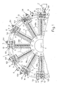
Fig. 1 is a top plan view of a support base with rotating supports on which the workpiece is fixed with adhesive; -
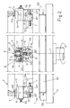
Fig. 2 shows the base according toFigure 1 sectioned along the line II-II. - In the
figures, 1 denotes a support base or plate which has, for example, acoaxial plinth 101 by means of which the said base, firstly during mounting thereon of the workpiece to be machined by the machine tool, may be gripped by the grippingjaws 102 of a table 2 which is rotatable about a vertical axis Y and together with which, once mounting of the workpiece has been performed, the said base 1 may then be gripped on the chuck of the machine tool for machining the workpiece. The table 2 may be rotated about its axis manually or by means of a special servo control unit (not shown) and means may be envisaged for locking it in the angular position into which it is brought in each case. - The workpiece P usually has an annular shape and in the example in question consists of the ring, also of large diameter and with external teeth, of a thrust bearing. According to the invention, supports 3, which where necessary may be rotated about their axes A, are mounted on the base 1, equally spaced and in a parallel arrangement with respect to the axis of the said base. In the first tests carried out, the
supports 3 were rotatably mounted in holes pre-formed in the base 1 so as to form with theirtop surface 103 an annular surface having a diameter which is correlated to that of the workpiece P, concentric with and perpendicular to the axis of the support base 1. Thesaid supports 3 had, underneath theirhead 103, a configuration in the form of a cube or with at least two parallel surfaces, so as to be able, where necessary, to be gripped and rotated about their axes, using an open-ended spanner of adequate length. - A metered and predetermined quantity of adhesive is deposited on the
clean top surface 103 of thesupports 3 and the bottom side of the workpiece P is then placed on this surface, said workpiece being aligned axially with precision in relation to the base 1 before the adhesive starts to set, for example by means of external reference gauges R which are designed, for example, for mounting on the base 1. or on the table 2 and for co-operation with the outer surface of the workpiece P, for example with three of these reference gauges R arranged angularly equidistant from each other at 120°. Once solidification of the adhesive for fixing the workpiece P onto thesupports 3 has occurred, theclamps 102 are slackened and, using the special eyebolts of the base 1 (not shown), the said base 1 with the fixed workpiece P is removed from the table 2 and is mounted on the self-centring chuck - usually with a vertical axis - of a machine tool which will perform machining of the visible surfaces of the said workpiece P, while the base 1 with the workpiece machined during the previous cycle is positioned on the table 2, in order for the workpiece to be detached from thesupports 3 of this base and replaced with a new workpiece. FromFigure 2 it can be seen that thesupport surface 103 of thesupports 3 is such as not to project from the plan-view volume of the workpiece P and that the latter is suitably spaced from the underlying wider parts of the said supports 3 so that the workpiece P may be precisely machined over the entire visible surface, without the tool interfering with thesupports 3. - It must be remembered that machining of the workpieces in question on the machine tool requires a relatively long time, i.e. about 20-30 minutes, so that the step of separating and preparing a new workpiece may be performed within this sufficiently long time interval. In order to separate the machined workpiece from the
supports 3, with the base 1 fixed on the table 2, it is envisaged to impart to thesaid supports 3 which are suitably designed in this connection, as mentioned above, a rotation about their axes A so as to break easily the bond formed by the thin adhesive fixing film, owing also to the small area of thetop surface 103 of eachsupport 3. During this step the workpiece is not subject to any damaging or negative stresses. The separating operation may be performed manually by the operator who uses a spanner in order to rotate thesupports 3 which are suitably designed for such an engaging manoeuvre, or may be performed mechanically, making use of rotation of the table 2 in order to position the appropriate mechanical interfaces of the said supports 3 (see below) in relation to one or more rotational actuators Z which are located statically outside the table 2. - Once separation of the workpiece P from the
supports 3 has been performed, making use of rotation of the table 2, it is possible to position progressively thesurface 103 of thesupports 3 in relation to at least one station (not shown) which performs cleaning of said surface of the supports, in order to remove from the latter any residual adhesive used during the previous step, following which a suitable amount of adhesive is positioned on this cleaned surface of thesupports 3 by means of one or more stations (not shown) with respect to which thesupports 3 may be positioned by means of rotation of the table 2, following which the cycle described for fixing and centring a new workpiece P on thesupports 3 is repeated. - A possible mode of designing and fastening supports 3 onto the base 1 is now described purely by way of a non-limiting example, said supports 3 being able to be operated by means of the said automatic rotating station Z and being mounted on means which allow a variation in the distance of these supports from the centre of rotation of the base 1, in order to support workpieces P with a different diameter.
- From the figures it can be seen that the
supports 3 are each formed by the output shaft of asmall reduction unit 10 which comprisesworm 4 andhelical gear 5 and which is fixed with itsbody 210 on aslide 6 which slides precisely insidestraight guides 106 arranged radially on the base 1 and which may be slid or locked in these guides by means of a system comprisingscrew nut 107, situated inside theslide 6, andscrew 7, arranged in a parallel manner inside theguides 106, supported rotatably by the base 1 and provided at the end with ahead 207 for connection to a rotating crank. Thescrews 7 and/or theguides 106 may be protected by special bellows or using other suitable means, which are not shown since they can be deduced by persons skilled in the art. The base 1 will be provided with metric scales (not shown) with which reference gauges which are fixed to theslides 6 or to the body of the reduction unit mounted on the latter co-operate, in order to display the radial position of the various reduction units with the associatedrotating supports 3. It is also possible to use, for rotation of thescrews 7, the same actuator Z according toFigure 1 which is used to operate thehead 104 of thescrews 4 of thereduction units 10, in order to separate the machined workpiece. - From the detail shown in
Figure 2 it can be seen that eachsupport 3 is formed by a disc of suitable thickness with a shape, in plan view, in the form of a circle segment, which by means of a pair ofscrews 8 and acentring pin 9 is removably fixed onto the top end of ahollow shaft 11 which is able to rotate with precision and with a low coefficient of friction inside a bush 12 or other suitable means placed inside a seat of thecover 110 of thereduction unit 10. Thehollow shaft 11 projects by a small amount from the bottom of the bush 12 so as to be able to mount thereon aring 112 with a low coefficient of friction, which rests on the bottom end of the said bush and against which thehelical gear 5 is pressed byscrews 13 which fix it to the saidhollow shaft 11. Thegear 5 is also axially hollow so that, when theupper disc 3 is not present, it is possible to engage a spanner with the socket head of ascrew 14 which passes through a hole provided in the bottom of thebody 210 of the reduction unit and is screwed into a hole of aplug 15 seated in the widened base of aguide groove 16 which has the form of an overturned T and is formed in theslide 6 and which at the top is engaged by a linear, bottom, raisedpart 310 of the body of thereduction unit 10. - Since the step of cleaning the
active surface 103 of thediscs 3 may result in a gradual reduction in the thickness of these components, also owing to periodic grinding operations, thesame discs 3 may be periodically replaced with new discs, by means of a simple and rapid operation.
Claims (10)
- Method for fixing precisely with adhesive, on a preparation and support plate or base (1), workpieces (P) to be machined by machine tools and for subsequent simplified separation of the said workpieces, characterized in that the surface for resting and supporting the workpiece (P) is formed by the flat top surface (103) of an annular arrangement of small supports (3) which are positioned with their axes (A) parallel in relation to that of the said base (1), on which the said workpiece must be placed and which is designed to be gripped by the chuck of the machine tool, the said supports (3) being mounted on the said base (1) with the possibility of being operated so as to rotate about their axes, it being envisaged that a suitable amount of adhesive is arranged on the top surface (103) of these supports and the workpiece whose visible surfaces are to be machined is then placed and correctly centred on the said surface, all of which so that, after machining of this workpiece, it may be separated from the said supports (3) by imparting to the latter a small rotation about their axes (A) so as to break the bond of the adhesive surface situated in between, without the workpiece itself being subject to damaging stresses.
- Apparatus for fixing precisely with adhesive, on a preparation and support plate or base (1), workpieces (P) to be machined by machine tools and for subsequent simplified separation of these workpieces, in particular for implementing the method according to Claim 1, comprising, on the said support base (1), a plurality of small supports (3), characterized in that the plurality of small supports (3) form an annular rim with a diameter correlated to that of the workpiece (P) and coaxial with the said base (1) and are designed to be operated so as to rotate about their axes (A) parallel to that of the said base (1) and, with their visible surface (103), form an annular, flat, support surface which is perfectly perpendicular to the axis of the said support base (1).
- Apparatus according to Claim 2, characterized in that it envisages the use of a table (2) rotatable about its vertical axis (Y), with manual or mechanically operated rotation, and provided with self-centring gripping jaws (102) for gripping the said support base (1), all of which so as to be able to use rotation of this table in order to position in succession the supports (3) of the said base (1) in relation to one or more fixed rotating stations (Z), one or more fixed stations for cleaning the said supports and one or more fixed stations for the metered distribution, on the said supports (3), of the adhesive for fixing the workpiece (P) thereon.
- Apparatus according to claim 3, in which the support base (1) or the table (2) are designed for being able to mount thereon reference gauges (R) which allow the correct centring of the workpiece (P) on the supports (3) previously provided with the appropriate amount of adhesive.
- Apparatus according to Claim 2, in which the supports (3) may be rotatably mounted in holes pre-formed in the support base (1) so as to form with their top surface (103) an annular surface with a diameter correlated to that of the workpiece (P), which is concentric with and perpendicular to the axis of the said support base (1), the said supports (3) being characterized in that they have, underneath their head (103), a configuration in the form of a cube or with at least two parallel surfaces, so as to be able, where necessary, to be gripped and rotated about their axes, using an open-ended spanner of adequate length.
- Apparatus according to Claim 2, in which the support surface (103) of the supports (3) is such as not to project from the plan-view volume of the workpiece (P) so that the said workpiece may be precisely machined over the entire visible surface, without interference with the said supports (3).
- Apparatus according to Claim 2, in which the supports (3) are each formed by the output shaft of a small reduction unit (10) which comprises worm screw (4) and helical gear (5) and which is fixed with its body (210) on a slide (6) which slides precisely inside straight guides (106) arranged radially on the support base (1) and which may be slid or locked inside these guides by means of a system comprising screw nut (107), situated inside the slide (6), and screw (7), arranged in a parallel manner inside the said guides (106), rotatably supported by the base (1) and provided at its end with a head (207) for connection to rotating means.
- Apparatus according to Claim 7, in which the support base (1) may be provided with metric scales with which the reference gauges fixed to the said slides (6) or to the body of the reduction unit (10) mounted on the latter co-operate, in order to display the radial position of the various reduction units with the associated rotating supports (3).
- Apparatus according to Claim 7, in which each support (3) is formed by a disc of suitable thickness with a shape, in plan view, in the form of a circle segment, which by means of screws (8) and a centring pin (9) is removably and interchangeably fixed on the top end of a hollow shaft (11) which is able to rotate precisely and with a low coefficient of friction inside a bush (12) or other suitable means positioned in a seat of the cover (110) of the reduction unit (10), this hollow shaft (11) projecting with a short section from the bottom of the said bush (12) so as to be able to mount thereon a ring (112) with a low coefficient of friction, which rests on the bottom end of the said bush (12) and against which the helical gear (5) of the reduction unit is pressed by means of screws (13) which fix it to the said hollow shaft (11).
- Apparatus according to Claim 9, in which the helical gear (5) is also axially hollow so that, when the said upper disc is not present, it is possible to engage a spanner with the socket head of a screw (14) which passes through a hole provided in the bottom of the body (210) of the reduction unit and which is screwed into a hole of a securing plug (15) housed in the widened base of a guide groove (16) which has the form of an overturned T and is formed in the said slide (6) and which at the top is engaged by a linear, bottom, raised part (310) of the body of the reduction unit (10).
Applications Claiming Priority (2)
| Application Number | Priority Date | Filing Date | Title |
|---|---|---|---|
| IT000295A ITBO20060295A1 (en) | 2006-04-18 | 2006-04-18 | METHOD AND APPARATUS FOR PRECISION FIXING AND WITH ADHESIVE, ON A PREPARATION AND SUPPORT PALETTE, OF PIECES TO BE WORKED TO MACHINE TOOLS AND FOR THE NEXT SIMPLIFIED DETACHMENT OF THE SAME PIECES. |
| PCT/EP2007/052823 WO2007118761A1 (en) | 2006-04-18 | 2007-03-23 | Method and apparatus for fixing, on a preparation and support plate, workpieces to be machined by machine tools |
Publications (2)
| Publication Number | Publication Date |
|---|---|
| EP2007547A1 EP2007547A1 (en) | 2008-12-31 |
| EP2007547B1 true EP2007547B1 (en) | 2010-05-19 |
Family
ID=38229864
Family Applications (1)
| Application Number | Title | Priority Date | Filing Date |
|---|---|---|---|
| EP07727297A Not-in-force EP2007547B1 (en) | 2006-04-18 | 2007-03-23 | Method and apparatus for fixing, on a preparation and support plate, workpieces to be machined by machine tools |
Country Status (9)
| Country | Link |
|---|---|
| US (1) | US20090134560A1 (en) |
| EP (1) | EP2007547B1 (en) |
| JP (1) | JP5160537B2 (en) |
| CN (1) | CN101426614B (en) |
| AT (1) | ATE468198T1 (en) |
| DE (1) | DE602007006652D1 (en) |
| ES (1) | ES2345684T3 (en) |
| IT (1) | ITBO20060295A1 (en) |
| WO (1) | WO2007118761A1 (en) |
Families Citing this family (9)
| Publication number | Priority date | Publication date | Assignee | Title |
|---|---|---|---|---|
| CN101954604B (en) * | 2010-07-30 | 2013-07-03 | 东方电气集团东方汽轮机有限公司 | Annular thin-wall article clamping device and using method thereof |
| JP2012245592A (en) * | 2011-05-30 | 2012-12-13 | Mitsubishi Heavy Ind Ltd | Machining tool for vertical cutting device |
| US10018211B2 (en) | 2014-02-11 | 2018-07-10 | GM Global Technology Operations LLC | Bond standoffs for sliding positioning of components in an assembly |
| CN104759898A (en) * | 2015-03-18 | 2015-07-08 | 常州天山重工机械有限公司 | Auxiliary support devices for large rotation work table |
| CN107297596B (en) * | 2017-07-12 | 2024-01-26 | 南京博物院 | Cultural relic orthopedic instrument |
| FR3080554B1 (en) | 2018-04-25 | 2021-03-12 | Skf Ab | MACHINE FOR GLUING A PART ON A SUPPORT ELEMENT BEFORE MACHINING OPERATIONS AND ITS PROCESS |
| CN110170871B (en) * | 2019-05-15 | 2023-09-01 | 深圳市圆梦精密技术研究院 | Automatic clamping device |
| CN110712047B (en) * | 2019-11-15 | 2021-06-29 | 贵州航天南海科技有限责任公司 | Rigid support method for thin-wall cavity part machining |
| CN110883633B (en) * | 2019-11-25 | 2021-09-07 | 哈尔滨工业大学 | A positioning support clamping device for large thin-walled cylindrical parts |
Family Cites Families (8)
| Publication number | Priority date | Publication date | Assignee | Title |
|---|---|---|---|---|
| US3175820A (en) * | 1962-11-09 | 1965-03-30 | Portage Machine Company | Rotary table having trimetric adjustment features |
| NO138197C (en) * | 1973-08-20 | 1978-07-26 | Avondale Shipyards Inc | PROCEDURE AND DEVICE FOR MACHINING OF LARGE, COMPLEX, CURVED WORKS |
| JPS5138181A (en) * | 1974-09-28 | 1976-03-30 | Mitsubishi Heavy Ind Ltd | SETSUCHAKUZAIO RYOSHITAKAKOHOHO |
| JPS61226203A (en) * | 1985-03-29 | 1986-10-08 | Agency Of Ind Science & Technol | Adapter for chuck |
| DE19920365A1 (en) * | 1999-05-04 | 2000-11-30 | Emil Stark | Fastening and detachment of workpiece and carrier for precision processing, e.g. machining, employs intervening adhesive layer, forming attachment in accurate registration |
| DE10029379A1 (en) * | 2000-06-20 | 2002-01-17 | Univ Hannover | Work piece fixing device using adhesive connection, comprising easy removal mechanism |
| ITBO20020009A1 (en) * | 2002-01-10 | 2003-07-10 | Minganti Spa | PROCEDURE AND APPARATUS FOR SUBJECTING PIECES OF ANULAR FORM TO HIGH PRECISION PROCESSING ON INTERNAL AND / OR EXTERNAL SURFACES, WITH |
| US7524390B2 (en) * | 2006-03-27 | 2009-04-28 | The Penn State Research Foundation | Fixture and method of holding and debonding a workpiece with the fixture |
-
2006
- 2006-04-18 IT IT000295A patent/ITBO20060295A1/en unknown
-
2007
- 2007-03-23 WO PCT/EP2007/052823 patent/WO2007118761A1/en not_active Ceased
- 2007-03-23 JP JP2009505819A patent/JP5160537B2/en not_active Expired - Fee Related
- 2007-03-23 ES ES07727297T patent/ES2345684T3/en active Active
- 2007-03-23 AT AT07727297T patent/ATE468198T1/en active
- 2007-03-23 CN CN2007800137962A patent/CN101426614B/en not_active Expired - Fee Related
- 2007-03-23 US US12/297,233 patent/US20090134560A1/en not_active Abandoned
- 2007-03-23 EP EP07727297A patent/EP2007547B1/en not_active Not-in-force
- 2007-03-23 DE DE602007006652T patent/DE602007006652D1/en active Active
Also Published As
| Publication number | Publication date |
|---|---|
| WO2007118761A1 (en) | 2007-10-25 |
| US20090134560A1 (en) | 2009-05-28 |
| EP2007547A1 (en) | 2008-12-31 |
| JP5160537B2 (en) | 2013-03-13 |
| CN101426614A (en) | 2009-05-06 |
| ITBO20060295A1 (en) | 2007-10-19 |
| ATE468198T1 (en) | 2010-06-15 |
| JP2009534197A (en) | 2009-09-24 |
| DE602007006652D1 (en) | 2010-07-01 |
| CN101426614B (en) | 2011-02-16 |
| ES2345684T3 (en) | 2010-09-29 |
Similar Documents
| Publication | Publication Date | Title |
|---|---|---|
| US20090134560A1 (en) | Method and apparatus for fixing, on a preparation and support plate, workpieces to be machined by machine tools | |
| TWI430862B (en) | Gear processing machinery | |
| JP2013543449A (en) | Module structure for supporting semi-finished products | |
| GB2510457A (en) | Method and apparatus for forming thin discs | |
| CA3022210C (en) | Circular saw mounting device | |
| EP1737611B1 (en) | Method for centring semi-finished parts which are to undergo mechanical machining | |
| JPH1177488A (en) | Index attachment | |
| CN211332760U (en) | Cylindrical workpiece tool of double-end-face grinding machine | |
| US20100166519A1 (en) | Clamping method for workpieces used for the production of compressor or turbine wheels | |
| CN215200712U (en) | Lathe fixture for turbine disc of aircraft engine | |
| JP2013202746A (en) | Rotation support jig for processing machine | |
| CN105081875A (en) | Six-hole gasket machining clamp | |
| CN208358306U (en) | A kind of multi-purpose built-up jig | |
| CN114273872B (en) | Machining method of thin-wall bearing ring forging | |
| KR200430073Y1 (en) | Chuck for Aluminum Wheel Machining | |
| CN110293450B (en) | Dynamometer clamp suitable for five-axis machine tool | |
| WO2004024377A1 (en) | System for machining end part of steel pipe and method and system for adjusting tool rest for use therein | |
| CN216176733U (en) | Three-jaw base high-precision clamping device for machine tool machining | |
| CN223734620U (en) | Clamp device for floating positioning honing cycloidal gear aliquoting holes | |
| JP2006341355A (en) | Centering support method and centering support device for workpiece | |
| WO2007099653A1 (en) | Vertical-type double-head surface grinding machine for machining brake disk | |
| CN223418981U (en) | A sealing ring processing and finishing tool | |
| CN218254040U (en) | Assembled part integral tool | |
| JP2003053634A (en) | Rotary work table device | |
| CN215090769U (en) | Clamp for rotary body |
Legal Events
| Date | Code | Title | Description |
|---|---|---|---|
| PUAI | Public reference made under article 153(3) epc to a published international application that has entered the european phase |
Free format text: ORIGINAL CODE: 0009012 |
|
| 17P | Request for examination filed |
Effective date: 20081016 |
|
| AK | Designated contracting states |
Kind code of ref document: A1 Designated state(s): AT BE BG CH CY CZ DE DK EE ES FI FR GB GR HU IE IS IT LI LT LU LV MC MT NL PL PT RO SE SI SK TR |
|
| AX | Request for extension of the european patent |
Extension state: AL BA HR MK RS |
|
| RIC1 | Information provided on ipc code assigned before grant |
Ipc: B23Q 3/08 20060101AFI20090803BHEP Ipc: B23Q 7/02 20060101ALN20090803BHEP |
|
| GRAP | Despatch of communication of intention to grant a patent |
Free format text: ORIGINAL CODE: EPIDOSNIGR1 |
|
| GRAS | Grant fee paid |
Free format text: ORIGINAL CODE: EPIDOSNIGR3 |
|
| GRAA | (expected) grant |
Free format text: ORIGINAL CODE: 0009210 |
|
| AK | Designated contracting states |
Kind code of ref document: B1 Designated state(s): AT BE BG CH CY CZ DE DK EE ES FI FR GB GR HU IE IS IT LI LT LU LV MC MT NL PL PT RO SE SI SK TR |
|
| REG | Reference to a national code |
Ref country code: GB Ref legal event code: FG4D |
|
| REG | Reference to a national code |
Ref country code: CH Ref legal event code: EP |
|
| REG | Reference to a national code |
Ref country code: IE Ref legal event code: FG4D |
|
| REF | Corresponds to: |
Ref document number: 602007006652 Country of ref document: DE Date of ref document: 20100701 Kind code of ref document: P |
|
| REG | Reference to a national code |
Ref country code: SE Ref legal event code: TRGR |
|
| REG | Reference to a national code |
Ref country code: NL Ref legal event code: VDEP Effective date: 20100519 |
|
| REG | Reference to a national code |
Ref country code: ES Ref legal event code: FG2A Ref document number: 2345684 Country of ref document: ES Kind code of ref document: T3 |
|
| LTIE | Lt: invalidation of european patent or patent extension |
Effective date: 20100519 |
|
| PG25 | Lapsed in a contracting state [announced via postgrant information from national office to epo] |
Ref country code: LT Free format text: LAPSE BECAUSE OF FAILURE TO SUBMIT A TRANSLATION OF THE DESCRIPTION OR TO PAY THE FEE WITHIN THE PRESCRIBED TIME-LIMIT Effective date: 20100519 |
|
| PG25 | Lapsed in a contracting state [announced via postgrant information from national office to epo] |
Ref country code: SI Free format text: LAPSE BECAUSE OF FAILURE TO SUBMIT A TRANSLATION OF THE DESCRIPTION OR TO PAY THE FEE WITHIN THE PRESCRIBED TIME-LIMIT Effective date: 20100519 Ref country code: FI Free format text: LAPSE BECAUSE OF FAILURE TO SUBMIT A TRANSLATION OF THE DESCRIPTION OR TO PAY THE FEE WITHIN THE PRESCRIBED TIME-LIMIT Effective date: 20100519 Ref country code: IS Free format text: LAPSE BECAUSE OF FAILURE TO SUBMIT A TRANSLATION OF THE DESCRIPTION OR TO PAY THE FEE WITHIN THE PRESCRIBED TIME-LIMIT Effective date: 20100919 Ref country code: LV Free format text: LAPSE BECAUSE OF FAILURE TO SUBMIT A TRANSLATION OF THE DESCRIPTION OR TO PAY THE FEE WITHIN THE PRESCRIBED TIME-LIMIT Effective date: 20100519 |
|
| PG25 | Lapsed in a contracting state [announced via postgrant information from national office to epo] |
Ref country code: CY Free format text: LAPSE BECAUSE OF FAILURE TO SUBMIT A TRANSLATION OF THE DESCRIPTION OR TO PAY THE FEE WITHIN THE PRESCRIBED TIME-LIMIT Effective date: 20100609 Ref country code: PL Free format text: LAPSE BECAUSE OF FAILURE TO SUBMIT A TRANSLATION OF THE DESCRIPTION OR TO PAY THE FEE WITHIN THE PRESCRIBED TIME-LIMIT Effective date: 20100519 |
|
| PG25 | Lapsed in a contracting state [announced via postgrant information from national office to epo] |
Ref country code: DK Free format text: LAPSE BECAUSE OF FAILURE TO SUBMIT A TRANSLATION OF THE DESCRIPTION OR TO PAY THE FEE WITHIN THE PRESCRIBED TIME-LIMIT Effective date: 20100519 Ref country code: NL Free format text: LAPSE BECAUSE OF FAILURE TO SUBMIT A TRANSLATION OF THE DESCRIPTION OR TO PAY THE FEE WITHIN THE PRESCRIBED TIME-LIMIT Effective date: 20100519 Ref country code: EE Free format text: LAPSE BECAUSE OF FAILURE TO SUBMIT A TRANSLATION OF THE DESCRIPTION OR TO PAY THE FEE WITHIN THE PRESCRIBED TIME-LIMIT Effective date: 20100519 Ref country code: PT Free format text: LAPSE BECAUSE OF FAILURE TO SUBMIT A TRANSLATION OF THE DESCRIPTION OR TO PAY THE FEE WITHIN THE PRESCRIBED TIME-LIMIT Effective date: 20100920 |
|
| PG25 | Lapsed in a contracting state [announced via postgrant information from national office to epo] |
Ref country code: SK Free format text: LAPSE BECAUSE OF FAILURE TO SUBMIT A TRANSLATION OF THE DESCRIPTION OR TO PAY THE FEE WITHIN THE PRESCRIBED TIME-LIMIT Effective date: 20100519 Ref country code: CZ Free format text: LAPSE BECAUSE OF FAILURE TO SUBMIT A TRANSLATION OF THE DESCRIPTION OR TO PAY THE FEE WITHIN THE PRESCRIBED TIME-LIMIT Effective date: 20100519 Ref country code: RO Free format text: LAPSE BECAUSE OF FAILURE TO SUBMIT A TRANSLATION OF THE DESCRIPTION OR TO PAY THE FEE WITHIN THE PRESCRIBED TIME-LIMIT Effective date: 20100519 |
|
| PLBE | No opposition filed within time limit |
Free format text: ORIGINAL CODE: 0009261 |
|
| STAA | Information on the status of an ep patent application or granted ep patent |
Free format text: STATUS: NO OPPOSITION FILED WITHIN TIME LIMIT |
|
| 26N | No opposition filed |
Effective date: 20110222 |
|
| PG25 | Lapsed in a contracting state [announced via postgrant information from national office to epo] |
Ref country code: GR Free format text: LAPSE BECAUSE OF FAILURE TO SUBMIT A TRANSLATION OF THE DESCRIPTION OR TO PAY THE FEE WITHIN THE PRESCRIBED TIME-LIMIT Effective date: 20100820 |
|
| PGRI | Patent reinstated in contracting state [announced from national office to epo] |
Ref country code: IT Effective date: 20110501 |
|
| REG | Reference to a national code |
Ref country code: DE Ref legal event code: R097 Ref document number: 602007006652 Country of ref document: DE Effective date: 20110221 |
|
| PGRI | Patent reinstated in contracting state [announced from national office to epo] |
Ref country code: IT Effective date: 20110501 |
|
| PG25 | Lapsed in a contracting state [announced via postgrant information from national office to epo] |
Ref country code: MC Free format text: LAPSE BECAUSE OF NON-PAYMENT OF DUE FEES Effective date: 20110331 |
|
| REG | Reference to a national code |
Ref country code: CH Ref legal event code: PL |
|
| GBPC | Gb: european patent ceased through non-payment of renewal fee |
Effective date: 20110323 |
|
| PG25 | Lapsed in a contracting state [announced via postgrant information from national office to epo] |
Ref country code: MT Free format text: LAPSE BECAUSE OF FAILURE TO SUBMIT A TRANSLATION OF THE DESCRIPTION OR TO PAY THE FEE WITHIN THE PRESCRIBED TIME-LIMIT Effective date: 20100519 |
|
| REG | Reference to a national code |
Ref country code: IE Ref legal event code: MM4A |
|
| PG25 | Lapsed in a contracting state [announced via postgrant information from national office to epo] |
Ref country code: CH Free format text: LAPSE BECAUSE OF NON-PAYMENT OF DUE FEES Effective date: 20110331 Ref country code: IE Free format text: LAPSE BECAUSE OF NON-PAYMENT OF DUE FEES Effective date: 20110323 Ref country code: LI Free format text: LAPSE BECAUSE OF NON-PAYMENT OF DUE FEES Effective date: 20110331 |
|
| PG25 | Lapsed in a contracting state [announced via postgrant information from national office to epo] |
Ref country code: GB Free format text: LAPSE BECAUSE OF NON-PAYMENT OF DUE FEES Effective date: 20110323 |
|
| PG25 | Lapsed in a contracting state [announced via postgrant information from national office to epo] |
Ref country code: LU Free format text: LAPSE BECAUSE OF NON-PAYMENT OF DUE FEES Effective date: 20110323 |
|
| PG25 | Lapsed in a contracting state [announced via postgrant information from national office to epo] |
Ref country code: BG Free format text: LAPSE BECAUSE OF FAILURE TO SUBMIT A TRANSLATION OF THE DESCRIPTION OR TO PAY THE FEE WITHIN THE PRESCRIBED TIME-LIMIT Effective date: 20100819 Ref country code: TR Free format text: LAPSE BECAUSE OF FAILURE TO SUBMIT A TRANSLATION OF THE DESCRIPTION OR TO PAY THE FEE WITHIN THE PRESCRIBED TIME-LIMIT Effective date: 20100519 |
|
| PG25 | Lapsed in a contracting state [announced via postgrant information from national office to epo] |
Ref country code: HU Free format text: LAPSE BECAUSE OF FAILURE TO SUBMIT A TRANSLATION OF THE DESCRIPTION OR TO PAY THE FEE WITHIN THE PRESCRIBED TIME-LIMIT Effective date: 20100519 |
|
| PGFP | Annual fee paid to national office [announced via postgrant information from national office to epo] |
Ref country code: AT Payment date: 20140326 Year of fee payment: 8 |
|
| REG | Reference to a national code |
Ref country code: ES Ref legal event code: PC2A Owner name: AKTIEBOLAGET SKF Effective date: 20140902 |
|
| REG | Reference to a national code |
Ref country code: DE Ref legal event code: R082 Ref document number: 602007006652 Country of ref document: DE Representative=s name: KOHL, THOMAS, DIPL.-ING. UNIV., DE |
|
| REG | Reference to a national code |
Ref country code: FR Ref legal event code: TP Owner name: AKTIEBOLAGET SKF, SE Effective date: 20140808 |
|
| REG | Reference to a national code |
Ref country code: DE Ref legal event code: R081 Ref document number: 602007006652 Country of ref document: DE Owner name: AKTIEBOLAGET SKF, SE Free format text: FORMER OWNER: MINGANTI INTERNATIONAL LTD., DUBLIN, IE Effective date: 20140909 |
|
| REG | Reference to a national code |
Ref country code: FR Ref legal event code: PLFP Year of fee payment: 9 |
|
| PGFP | Annual fee paid to national office [announced via postgrant information from national office to epo] |
Ref country code: IT Payment date: 20150326 Year of fee payment: 9 |
|
| PGFP | Annual fee paid to national office [announced via postgrant information from national office to epo] |
Ref country code: ES Payment date: 20150428 Year of fee payment: 9 Ref country code: DE Payment date: 20150601 Year of fee payment: 9 Ref country code: SE Payment date: 20150330 Year of fee payment: 9 |
|
| PGFP | Annual fee paid to national office [announced via postgrant information from national office to epo] |
Ref country code: BE Payment date: 20150330 Year of fee payment: 9 Ref country code: FR Payment date: 20150331 Year of fee payment: 9 |
|
| REG | Reference to a national code |
Ref country code: AT Ref legal event code: MM01 Ref document number: 468198 Country of ref document: AT Kind code of ref document: T Effective date: 20150323 |
|
| PG25 | Lapsed in a contracting state [announced via postgrant information from national office to epo] |
Ref country code: AT Free format text: LAPSE BECAUSE OF NON-PAYMENT OF DUE FEES Effective date: 20150323 |
|
| PG25 | Lapsed in a contracting state [announced via postgrant information from national office to epo] |
Ref country code: BE Free format text: LAPSE BECAUSE OF NON-PAYMENT OF DUE FEES Effective date: 20160331 |
|
| REG | Reference to a national code |
Ref country code: DE Ref legal event code: R119 Ref document number: 602007006652 Country of ref document: DE |
|
| REG | Reference to a national code |
Ref country code: SE Ref legal event code: EUG |
|
| PG25 | Lapsed in a contracting state [announced via postgrant information from national office to epo] |
Ref country code: SE Free format text: LAPSE BECAUSE OF NON-PAYMENT OF DUE FEES Effective date: 20160324 |
|
| REG | Reference to a national code |
Ref country code: FR Ref legal event code: ST Effective date: 20161130 |
|
| PG25 | Lapsed in a contracting state [announced via postgrant information from national office to epo] |
Ref country code: FR Free format text: LAPSE BECAUSE OF NON-PAYMENT OF DUE FEES Effective date: 20160331 Ref country code: DE Free format text: LAPSE BECAUSE OF NON-PAYMENT OF DUE FEES Effective date: 20161001 |
|
| PG25 | Lapsed in a contracting state [announced via postgrant information from national office to epo] |
Ref country code: IT Free format text: LAPSE BECAUSE OF NON-PAYMENT OF DUE FEES Effective date: 20160323 |
|
| PG25 | Lapsed in a contracting state [announced via postgrant information from national office to epo] |
Ref country code: ES Free format text: LAPSE BECAUSE OF NON-PAYMENT OF DUE FEES Effective date: 20160324 |
|
| REG | Reference to a national code |
Ref country code: ES Ref legal event code: FD2A Effective date: 20181205 |