EP2006964B1 - Tunable diode laser system with external resonator - Google Patents
Tunable diode laser system with external resonator Download PDFInfo
- Publication number
- EP2006964B1 EP2006964B1 EP20080010552 EP08010552A EP2006964B1 EP 2006964 B1 EP2006964 B1 EP 2006964B1 EP 20080010552 EP20080010552 EP 20080010552 EP 08010552 A EP08010552 A EP 08010552A EP 2006964 B1 EP2006964 B1 EP 2006964B1
- Authority
- EP
- European Patent Office
- Prior art keywords
- diode
- grating
- laser system
- rotation
- joints
- Prior art date
- Legal status (The legal status is an assumption and is not a legal conclusion. Google has not performed a legal analysis and makes no representation as to the accuracy of the status listed.)
- Active
Links
- 230000003287 optical effect Effects 0.000 claims abstract description 23
- 230000009471 action Effects 0.000 claims description 9
- 230000008859 change Effects 0.000 description 7
- 238000013461 design Methods 0.000 description 6
- 239000007787 solid Substances 0.000 description 5
- 230000007774 longterm Effects 0.000 description 4
- 238000004519 manufacturing process Methods 0.000 description 4
- 230000035945 sensitivity Effects 0.000 description 3
- 238000013519 translation Methods 0.000 description 3
- 230000008901 benefit Effects 0.000 description 2
- 230000003595 spectral effect Effects 0.000 description 2
- 230000001360 synchronised effect Effects 0.000 description 2
- 230000003667 anti-reflective effect Effects 0.000 description 1
- 238000011161 development Methods 0.000 description 1
- 230000003628 erosive effect Effects 0.000 description 1
- 230000002349 favourable effect Effects 0.000 description 1
- 238000012423 maintenance Methods 0.000 description 1
- 230000007246 mechanism Effects 0.000 description 1
- 238000000034 method Methods 0.000 description 1
- 230000008569 process Effects 0.000 description 1
- 239000004065 semiconductor Substances 0.000 description 1
- 230000035939 shock Effects 0.000 description 1
- 230000006641 stabilisation Effects 0.000 description 1
- 238000011105 stabilization Methods 0.000 description 1
- 238000012546 transfer Methods 0.000 description 1
Images

Classifications
-
- H—ELECTRICITY
- H01—ELECTRIC ELEMENTS
- H01S—DEVICES USING THE PROCESS OF LIGHT AMPLIFICATION BY STIMULATED EMISSION OF RADIATION [LASER] TO AMPLIFY OR GENERATE LIGHT; DEVICES USING STIMULATED EMISSION OF ELECTROMAGNETIC RADIATION IN WAVE RANGES OTHER THAN OPTICAL
- H01S5/00—Semiconductor lasers
- H01S5/10—Construction or shape of the optical resonator, e.g. extended or external cavity, coupled cavities, bent-guide, varying width, thickness or composition of the active region
- H01S5/14—External cavity lasers
- H01S5/141—External cavity lasers using a wavelength selective device, e.g. a grating or etalon
-
- G—PHYSICS
- G01—MEASURING; TESTING
- G01J—MEASUREMENT OF INTENSITY, VELOCITY, SPECTRAL CONTENT, POLARISATION, PHASE OR PULSE CHARACTERISTICS OF INFRARED, VISIBLE OR ULTRAVIOLET LIGHT; COLORIMETRY; RADIATION PYROMETRY
- G01J3/00—Spectrometry; Spectrophotometry; Monochromators; Measuring colours
- G01J3/02—Details
- G01J3/10—Arrangements of light sources specially adapted for spectrometry or colorimetry
-
- H—ELECTRICITY
- H01—ELECTRIC ELEMENTS
- H01S—DEVICES USING THE PROCESS OF LIGHT AMPLIFICATION BY STIMULATED EMISSION OF RADIATION [LASER] TO AMPLIFY OR GENERATE LIGHT; DEVICES USING STIMULATED EMISSION OF ELECTROMAGNETIC RADIATION IN WAVE RANGES OTHER THAN OPTICAL
- H01S5/00—Semiconductor lasers
- H01S5/02—Structural details or components not essential to laser action
- H01S5/022—Mountings; Housings
- H01S5/02208—Mountings; Housings characterised by the shape of the housings
- H01S5/02212—Can-type, e.g. TO-CAN housings with emission along or parallel to symmetry axis
-
- H—ELECTRICITY
- H01—ELECTRIC ELEMENTS
- H01S—DEVICES USING THE PROCESS OF LIGHT AMPLIFICATION BY STIMULATED EMISSION OF RADIATION [LASER] TO AMPLIFY OR GENERATE LIGHT; DEVICES USING STIMULATED EMISSION OF ELECTROMAGNETIC RADIATION IN WAVE RANGES OTHER THAN OPTICAL
- H01S5/00—Semiconductor lasers
- H01S5/02—Structural details or components not essential to laser action
- H01S5/022—Mountings; Housings
- H01S5/023—Mount members, e.g. sub-mount members
- H01S5/02325—Mechanically integrated components on mount members or optical micro-benches
- H01S5/02326—Arrangements for relative positioning of laser diodes and optical components, e.g. grooves in the mount to fix optical fibres or lenses
-
- H—ELECTRICITY
- H01—ELECTRIC ELEMENTS
- H01S—DEVICES USING THE PROCESS OF LIGHT AMPLIFICATION BY STIMULATED EMISSION OF RADIATION [LASER] TO AMPLIFY OR GENERATE LIGHT; DEVICES USING STIMULATED EMISSION OF ELECTROMAGNETIC RADIATION IN WAVE RANGES OTHER THAN OPTICAL
- H01S5/00—Semiconductor lasers
- H01S5/06—Arrangements for controlling the laser output parameters, e.g. by operating on the active medium
- H01S5/065—Mode locking; Mode suppression; Mode selection ; Self pulsating
- H01S5/0651—Mode control
- H01S5/0653—Mode suppression, e.g. specific multimode
- H01S5/0654—Single longitudinal mode emission
-
- H—ELECTRICITY
- H01—ELECTRIC ELEMENTS
- H01S—DEVICES USING THE PROCESS OF LIGHT AMPLIFICATION BY STIMULATED EMISSION OF RADIATION [LASER] TO AMPLIFY OR GENERATE LIGHT; DEVICES USING STIMULATED EMISSION OF ELECTROMAGNETIC RADIATION IN WAVE RANGES OTHER THAN OPTICAL
- H01S5/00—Semiconductor lasers
- H01S5/10—Construction or shape of the optical resonator, e.g. extended or external cavity, coupled cavities, bent-guide, varying width, thickness or composition of the active region
- H01S5/14—External cavity lasers
- H01S5/141—External cavity lasers using a wavelength selective device, e.g. a grating or etalon
- H01S5/143—Littman-Metcalf configuration, e.g. laser - grating - mirror
Definitions
- the invention relates to a tunable diode laser system with external resonator in Littrow or Littman configuration, with an optical grating, on which the light beam of a laser diode is diffracted, a holding element for holding the grating or for holding a mirror, which diffracted on the grating Reflected light, and with an actuator for changing the position of the grid or the mirror.
- the spectral bandwidth of the laser emission can be significantly reduced.
- An external resonator also allows the tuning of the laser wavelength.
- Known from the prior art are configurations with feedback via an optical grating, at which the light generated by means of the laser diode is diffracted.
- the grating may be at the front of the laser diode, i. be arranged in the useful beam, or at the back of the laser diode, in the latter case, the feedback takes place via the Endfacette the laser diode.
- the light emitted by the laser diode is collimated by means of collimation optics and diffracted at the optical grating.
- the light of the zeroth diffraction order is coupled out as a useful beam, whereas the light of the first diffraction order is reflected back into the laser diode so that the diffraction grating and the end facet of the laser diode form a resonator.
- the tuning of the wavelength takes place with a diode laser in Littrow configuration Rotation of the optical grating.
- This rotation causes a change in the angle of incidence of the laser beam on the grating and, consequently, a variation in the wavelength of the resonantly-coupled first diffraction order.
- the length of the optical resonator must be varied simultaneously with the change in the angle of rotation of the diffraction grating, so that the same laser mode always prevails in the resonator.
- a coordinated change in angle and length is realized when the diffraction grating is rotated about a center of rotation defined by the intersection of the planes of the surface of the optical grating and the end facet of the laser diode.
- diode laser systems are known in the so-called Littman configuration.
- the laser beam emitted from a laser diode is also diffracted at an optical grating, but the first diffraction order light falls on a mirror which reflects the light back onto the diffraction grating.
- the mirror forms an optical resonator with the end facet of the laser diode.
- To tune the wavelength of the mirror is rotated. This rotation changes the angle between the first order diffracted beam and the normal of the optical grating. As a result, the resonance condition is specified.
- the mirror For mode-free wavelength tuning, in a Littman-configured diode laser system, the mirror must be rotated about a center of rotation defined by the intersection of three planes.
- a tunable diode laser system of the type specified, in which actuators are provided for changing the position of the grid, is known from the prior art ( J. Hult et al., "Wide-bandwidth mode-hop-free tuning of extended cavity GaN diode lasers", Applied Optics, 20.06.2005, Vol. 44, No. 18, pp. 3675-3679 ).
- a holding element for holding the diffraction grating is provided.
- the holding element comprises two piezoactuators, which cause a rotation of the diffraction grating and a synchronous change in the length of the optical resonator. The rotation takes place around a (virtual) turning center, which is defined by the actuation of the piezoactuators.
- the US 5,802,085 discloses a tunable laser light source, again in the form of a diode laser with external resonator in Littrow configuration.
- the diffraction grating is mounted on a movable support in a manner that enables synchronous translation and rotation effected by a single actuator.
- the US 6,049,554 also describes a tunable external cavity diode laser in which the wavelength is selectable by simultaneous rotation and linear translation of a reflector. By suitable choice of The center of rotation of the movement, the diode laser over a wide spectral range is continuously tuned.
- a continuous mode jump-free tuning of the wavelength can be effected by means of a single actuator.
- the diffraction grating (in Littrow configuration) or the mirror (in Littman configuration) are reliably rotated around the correct rotation center.
- the holding element comprises a carrier for the grid or for the mirror and a base body, wherein the carrier is connected to the main body via joints, namely solid joints.
- the arrangement and design of these joints determines how the linear deflection of the actuator is converted into a rotational movement of the carrier.
- the arrangement and design of the joints as well as the position of the point of action of the actuator on the carrier define precisely and reproducibly the center of rotation.
- the center of rotation is outside the joints and outside of the main body of the support member. This means that the (virtual) center of rotation lies outside a surface that is spanned by the joints and outside the outer boundary of the body. This advantageously allows a particularly compact design.
- the laser system according to the invention uses a single actuator.
- a complex control electronics for the coordinated deflection of multiple actuators is not required in the system according to the invention.
- the system according to the invention comprises only a few with comparatively low cost manufacturable components, so that the system is a total cost-effectively.
- Another advantage of the system according to the invention is that it is relatively insensitive to mechanical vibrations due to its compact dimensions.
- the joints of the diode laser system according to the invention are elastic solid-state joints, the rigidity of which can be deliberately predetermined over the lengths and the thicknesses of the joint sections.
- the individual joints can be different stiff.
- the (virtual) center of rotation can be specified in the production of the holding element by appropriate dimensioning of the individual joints, without otherwise the mechanics would have to be adjusted.
- the design of the joints in terms of their rigidity, the mechanical resonance frequencies can be influenced so that the sensitivity to mechanical vibrations is low and a particularly fast tuning of the wavelength by means of the actuator is possible.
- the carrier and the base body are integrally formed with each other (monolithic).
- known electroerosion processes such as wire erosion, can be used. This in turn has a favorable effect on the cost and at the same time on the compactness of the overall arrangement.
- guide joints and at least one rotary joint are provided as solid joints.
- the guide joints cause guidance of the carrier in the plane of the light beam, while the rotary joint ensures that the linear deflection of the actuator is translated into rotation of the carrier about the desired center of rotation.
- the guide joints thus enable translation and rotation in the plane of the light beam.
- the rotation joint "ties" the carrier to the base body, which causes the inventive implementation of the linear deflection of the actuator in a rotation about the center of rotation lying outside the body.
- the solid state joints may be formed, for example, as plate or leaf spring joints.
- Such joints have translational and rotational degrees of freedom, wherein the flexural rigidity of the joints in the plane of the laser beam is advantageously smaller by orders of magnitude than in the direction perpendicular thereto.
- the guidance of the rotation of the grating or the mirror required for the purpose of tuning can be effected in a targeted manner.
- the position of the center of rotation can be adjusted by changing the position of the point of action of the actuator on the carrier.
- the position of the center of rotation can very easily be configured so that the position of the actuator and thus the position of the point of action of the actuator on the carrier can be changed.
- the adjustment can be advantageously carried out in such a way that the position of the point of action is changed in a direction parallel to the grid surface.
- the actual center of rotation can at least approximately be brought to coincide with the theoretically ideal center of rotation. It is exploited according to the invention that the position of the point of action in a well-defined manner, the implementation of the linear deflection of the actuator in the rotation of the carrier, to which the diffraction grating or the mirror is attached, influenced.
- the tuning effecting actuator in the simplest case may be a manually operable set screw, which is guided in a matching thread in the main body of the support member and determines the position of the carrier depending on the depth of engagement.
- a manually operable set screw which is guided in a matching thread in the main body of the support member and determines the position of the carrier depending on the depth of engagement.
- the holding element also comprises a bogie on which the base body is rotatably mounted in the plane of the light beam.
- This embodiment additionally allows a very simple (coarse) tuning of the laser system by rotation of the base body (and thus the grating or the mirror) relative to the bogie.
- the holding element is expediently designed such that the rotation of the optical grating or of the mirror takes place around the point of impingement of the laser beam on the grating or on the mirror. It can be used in this case, a small grid or a small mirror, which increases the resonant frequency of the arrangement by the correspondingly small size of the carrier and thus reduces the sensitivity to mechanical (acoustic) vibrations.
- An expedient development of the diode laser system provides that a diode holder for holding the laser diode and a collimating optics is provided.
- the diode holder comprises the laser diode and the collimating optics, wherein expediently the position of the laser diode relative to the collimating optics should be adjustable in order to obtain the best possible laser beam.
- the diode holder is rotatable for adjusting the angle of incidence on the grid. It is all about ensuring that the light beam hits the diffraction grating in such a way that the desired feedback of the diffracted light is produced in the laser diode.
- a particularly expedient embodiment of the laser system according to the invention provides that the diode holder is rotatably mounted on the bogie, namely about an axis of rotation perpendicular to the axis of rotation of the body. This results in a total of a very compact and closed structure. All components can be fixed together and so be fixed that a high long-term stability of the adjustment made is ensured. A high transport stability is ensured since hardly any torques are to be expected around the axis of rotation of the mounted on the bogie diode holder.
- Laser diodes according to the invention are any semiconductor lasers, e.g. Fabry-Perot laser diodes, antireflective coated (AR) laser diodes, active-zone trapezoidal geometry diodes, wide-band emitters, or the like.
- semiconductor lasers e.g. Fabry-Perot laser diodes, antireflective coated (AR) laser diodes, active-zone trapezoidal geometry diodes, wide-band emitters, or the like.
- the figures show an inventive tunable diode laser system with external resonator in Littrow configuration.
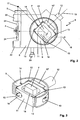
- the exploded view according to Fig. 1 shows the essential parts of the system.
- a lid 1 and a base plate 2 form the outer casing of the system.
- the electrical connections are housed.
- a Peltier element 3 For temperature stabilization of the laser resonator is a Peltier element 3.
- the central components of the diode laser system according to the invention are a laser diode 4, which is arranged on a diode holder 5, and a holding element 6 for holding an optical grating 7.
- the holding element comprises a bogie 8 and a base body. 9
- the base body 9 is rotatably mounted on the bogie 8 about a vertical axis of rotation. For this purpose, the circular base body 9 is inserted into the corresponding recess in the bogie 8.
- the wavelength of the light emitted by the diode laser system is roughly tunable by rotation of the base body 9 relative to the bogie 8.
- the rotation of the base body 9 takes place around the point of impact of the laser light beam of the laser diode 4 on the diffraction grating 7 around.
- a resonator 10 is screwed to fix the base body 9 in the vertical direction.
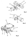
- the central element of the diode laser according to the invention is the holding element 6, whose structure in detail in the FIGS. 2 and 3 is shown.
- the holding element 6 comprises a carrier 11 on which the optical grating 7 is arranged.
- a piezoactuator 12 is provided, which is supported on the base body 9 and acts on the carrier 11.
- the main body 9 is connected to the carrier 11 via a total of five solid-state joints.
- These are four symmetrically arranged guide joints 13 and a rotary joint 14 which is arranged laterally offset from the deflection axis 15 of the actuator 12.
- the four guide joints 13 serve to guide the carrier 11 in the plane of the light beam 16 of the laser diode 4 and essentially determine the mechanical resonance frequencies of the system.
- the rotation joint 14 ensures that a linear deflection of the actuator 12 along the axis 15 is converted into a rotation of the carrier 11.
- the rotation center 17 is this rotation, as in the Fig. 2 represented outside the joints 13, 14 and in particular also outside the outer boundary of the base body 9.
- the center of rotation is defined by the intersection of the plane of the surface of the diffraction grating 7 and the plane of the Endfacette Laser diode 4.
- the rotation about the center of rotation 17 allows, as explained above, a mode jump-free tuning of the laser wavelength.
- the position of the center of rotation 17 is adjustable by changing the position of the point of action of the actuator 12 on the carrier 11 in a direction parallel to the plane of the grating 7 and also parallel to the rotary joint 14.
- the rotation joint 14 is in the plane of the grating 7.
- the point of action is defined by the intersection of the deflection axis 15 of the actuator 12 with the lateral surface of the carrier 11.
- the beam path of the laser light is shown.
- the laser beam 16 impinges on the diffraction grating 7.
- the light of the zeroth diffraction order is decoupled as a useful beam and leaves the laser system.
- the first diffraction order is reflected back into the laser diode 4, so that the grating 7 and the end facet of the laser diode 4 form an optical resonator.
- the useful beam is additionally reflected at a deflecting mirror 18.
- the deflecting mirror 18 is, as can be seen in the figures, arranged on the carrier 11, so that the position of the deflecting mirror 18 is fixed relative to the diffraction grating 7.
- the deflecting mirror compensates for the change in the angle of the laser beam during the tuning of the laser system. The angle change is converted into a small beam offset.
- the base body 9 is rotatably mounted on the bogie 8.
- a mechanical screw 20 which is screwed into the bogie 8 is used.
- the adjusting screw 20 acts on the base body 9, against the force a (not shown) return spring.
- the rotation takes place about a vertical axis of rotation which extends through the point of impact of the laser beam 16 on the grating 7. This makes it possible to use a small-sized diffraction grating 7, so that overall a very compact design is achieved.
- the diode holder 5 of the laser system according to the invention serves to hold the laser diode 4 and the collimating optics 21.
- the diode holder 5 is (at least in the areas in which it is guided on the bogie 8) substantially cylindrical.
- the bogie 8 has laterally on the shape of the diode holder 5 corresponding (half) cylindrical recess. This takes the diode holder 5, as in the Fig. 6 and 7 shown on.
- To fix the diode holder 5 to the bogie 8 are used with the bogie 8 screw-clamping clamps 22.
- the diode holder is rotatably mounted in this manner about a horizontal axis of rotation of the bogie 8.
- the direction of the laser beam can be adjusted in a vertical plane to produce the feedback of the light diffracted at the optical grating 7 into the laser diode 4.
- the adjustment made once has a good long-term stability, since torques around the axis of rotation of the diode holder 5 hardly occur even with strong mechanical stresses, such as shocks during transport. Due to the large contact surfaces between the diode holder 5 and the bogie 8 a good heat transfer is ensured.
- the overall very compact and closed unit of diode holder 5, bogie 8, body 9, carrier 11 and resonator 10 causes an extremely low thermal frequency drift of the laser system and low sensitivity to low-frequency (acoustic) mechanical vibrations.
- the laser diode 4 is adjustable by means of a clamping plate 23 relative to the collimating optics 21 in the transverse direction.
- the clamping plate 23 is fixed by means of two screws 24 to the diode holder 5.
- the collimating optical system 21 is displaceable parallel to the optical axis.
- a clamping ring 25 is the Collimating optics permanently fixable in the desired position.
- the collimating optics is in the simplest case a lens.
Landscapes
- Physics & Mathematics (AREA)
- Condensed Matter Physics & Semiconductors (AREA)
- General Physics & Mathematics (AREA)
- Electromagnetism (AREA)
- Optics & Photonics (AREA)
- Semiconductor Lasers (AREA)
Abstract
Description
Die Erfindung betrifft ein abstimmbares Diodenlasersystem mit externem Resonator in Littrow- oder Littman-Konfiguration, mit einem optischen Gitter, an dem der Lichtstrahl einer Laserdiode gebeugt wird, einem Halteelement zur Halterung des Gitters bzw. zur Halterung eines Spiegels, der das an dem Gitter gebeugte Licht reflektiert, und mit einem Aktuator zur Veränderung der Position des Gitters bzw. des Spiegels.The invention relates to a tunable diode laser system with external resonator in Littrow or Littman configuration, with an optical grating, on which the light beam of a laser diode is diffracted, a holding element for holding the grating or for holding a mirror, which diffracted on the grating Reflected light, and with an actuator for changing the position of the grid or the mirror.
Durch die Rückkopplung des Lichtes, das von einer Laserdiode eines Diodenlasers mit externem Resonator emittiert wird, kann die spektrale Bandbreite der Laseremission deutlich reduziert werden. Ein externer Resonator ermöglicht darüber hinaus das Abstimmen der Laserwellenlänge. Aus dem Stand der Technik bekannt sind Konfigurationen mit Rückkopplung über ein optisches Gitter, an dem das mittels der Laserdiode erzeugte Licht gebeugt wird. Das Gitter kann an der Vorderseite der Laserdiode, d.h. im Nutzstrahl, oder an der Rückseite der Laserdiode angeordnet sein, wobei im letzteren Fall die Rückkopplung über die Endfacette der Laserdiode erfolgt.By the feedback of the light emitted by a laser diode of an external cavity diode laser, the spectral bandwidth of the laser emission can be significantly reduced. An external resonator also allows the tuning of the laser wavelength. Known from the prior art are configurations with feedback via an optical grating, at which the light generated by means of the laser diode is diffracted. The grating may be at the front of the laser diode, i. be arranged in the useful beam, or at the back of the laser diode, in the latter case, the feedback takes place via the Endfacette the laser diode.
Bei Diodenlasern in so genannter Littrow-Konfiguration wird das von der Laserdiode emittierte Licht mittels einer Kollimationsoptik kollimiert und an dem optischen Gitter gebeugt. Das Licht der nullten Beugungsordnung wird als Nutzstrahl ausgekoppelt, das Licht der ersten Beugungsordnung wird hingegen in die Laserdiode zurückreflektiert, so dass das Beugungsgitter und die Endfacette der Laserdiode einen Resonator bilden. Die Abstimmung der Wellenlänge erfolgt bei einem Diodenlaser in Littrow-Konfiguration durch Drehung des optischen Gitters. Diese Drehung bewirkt eine Änderung des Einfallswinkels des Laserstrahls auf das Gitter und folglich eine Variation der Wellenlänge der resonant zurückgekoppelten ersten Beugungsordnung. Um das Diodenlasersystem modensprungfrei zu verstimmen, muss gleichzeitig mit der Änderung des Drehwinkels des Beugungsgitters die Länge des optischen Resonators variiert werden, so dass stets dieselbe Lasermode im Resonator vorherrscht. Eine koordinierte Winkel- und Längenänderung ist genau dann realisiert, wenn das Beugungsgitter um ein Drehzentrum gedreht wird, das durch die Schnittlinie der Ebenen der Oberfläche des optischen Gitters und der Endfacette der Laserdiode definiert ist. In der Praxis ist eine solche Drehachse nachteiligerweise nicht oder nur mit großem Aufwand akkurat realisierbar. Zudem führt der notwendigerweise lange Dreharm des Beugungsgitters zu einer sehr großen Bauform. Dies wiederum führt nachteiligerweise dazu, dass das System empfindlich auf niederfrequente mechanische Schwingungen reagiert und thermisch nur schwer kontrollierbar ist. Der lange Dreharm ist außerdem nachteilig, weil es aufgrund beim Transport einwirkender Kräfte leicht zur Dejustage kommen kann.In the case of diode lasers in the so-called Littrow configuration, the light emitted by the laser diode is collimated by means of collimation optics and diffracted at the optical grating. The light of the zeroth diffraction order is coupled out as a useful beam, whereas the light of the first diffraction order is reflected back into the laser diode so that the diffraction grating and the end facet of the laser diode form a resonator. The tuning of the wavelength takes place with a diode laser in Littrow configuration Rotation of the optical grating. This rotation causes a change in the angle of incidence of the laser beam on the grating and, consequently, a variation in the wavelength of the resonantly-coupled first diffraction order. In order to detune the diode laser system in a mode-free manner, the length of the optical resonator must be varied simultaneously with the change in the angle of rotation of the diffraction grating, so that the same laser mode always prevails in the resonator. A coordinated change in angle and length is realized when the diffraction grating is rotated about a center of rotation defined by the intersection of the planes of the surface of the optical grating and the end facet of the laser diode. In practice, such a rotation axis is disadvantageously not or only with great effort accurately realized. In addition, the necessarily long rotary arm of the diffraction grating leads to a very large design. This in turn leads disadvantageously to the fact that the system is sensitive to low-frequency mechanical vibrations and thermally difficult to control. The long rotary arm is also disadvantageous because it can easily come to misalignment due to the forces acting during transport.
Des Weiteren sind Diodenlasersysteme in der so genannten Littman-Konfiguration bekannt. Bei diesen Systemen wird der von einer Laserdiode emittierte Laserstrahl ebenfalls an einem optischen Gitter gebeugt, wobei jedoch das Licht der ersten Beugungsordnung auf einen Spiegel fällt, der das Licht auf das Beugungsgitter zurückreflektiert. Der Spiegel bildet mit der Endfacette der Laserdiode einen optischen Resonator. Zur Abstimmung der Wellenlänge wird der Spiegel gedreht. Durch diese Drehung ändert sich der Winkel zwischen dem gebeugten Strahl erster Ordnung und der Normalen des optischen Gitters. Hierdurch wird die Resonanzbedingung vorgegeben. Zum modensprungfreien Abstimmen der Wellenlänge muss bei einem Diodenlasersystem in Littman-Konfiguration der Spiegel um ein Drehzentrum gedreht werden, das durch die Schnittlinie dreier Ebenen definiert ist. Dies sind die Ebene der Endfacette der Laserdiode, die Ebene der Oberfläche des Beugungsgitters und die Ebene der Oberfläche des Spiegels. Die akkurate Realisierung dieses Drehzentrums erfordert in der Praxis eine sehr aufwendige Mechanik. Die Fertigung und Wartung solcher Lasersysteme ist entsprechend teuer und zeitintensiv. Eine fehlerhafte Position des Drehzentrums schränkt den modensprungfreien Abstimmbereich deutlich ein.Furthermore, diode laser systems are known in the so-called Littman configuration. In these systems, the laser beam emitted from a laser diode is also diffracted at an optical grating, but the first diffraction order light falls on a mirror which reflects the light back onto the diffraction grating. The mirror forms an optical resonator with the end facet of the laser diode. To tune the wavelength of the mirror is rotated. This rotation changes the angle between the first order diffracted beam and the normal of the optical grating. As a result, the resonance condition is specified. For mode-free wavelength tuning, in a Littman-configured diode laser system, the mirror must be rotated about a center of rotation defined by the intersection of three planes. These are the plane of the end facet of the laser diode, the plane of the surface of the diffraction grating and the plane of the surface of the mirror. The accurate realization of this center of rotation requires in practice a very complex mechanics. The manufacture and maintenance of such laser systems is correspondingly expensive and time-consuming. A faulty position of the center of rotation significantly limits the mode-hop-free tuning range.
Ein abstimmbares Diodenlasersystem der eingangs angegebenen Art, bei dem zur Veränderung der Position des Gitters Aktuatoren vorgesehen sind, ist aus dem Stand der Technik bekannt (
Aus der
Die
Die
Vor diesem Hintergrund ist es die Aufgabe der Erfindung, ein abstimmbares Diodenlasersystem bereitzustellen, das eine zuverlässige modensprungfreie Abstimmbarkeit ermöglicht und außerdem einfach und kostengünstig realisierbar ist.Against this background, it is the object of the invention to provide a tunable diode laser system, which allows a reliable mode jump-free tunability and also easy and inexpensive to implement.
Diese Aufgabe löst die Erfindung durch ein abstimmbares Diodenlasersystem mit externem Resonator in Littrow-Konfiguration gemäß Patentanspruch 1 sowie durch ein abstimmbares Diodenlasersystem in Littman-Konfiguration gemäß Patentanspruch 2.This object is achieved by a tunable diode laser system with external resonator in Littrow configuration according to
Bei dem erfindungsgemäßen Diodenlasersystem kann ein kontinuierliches modensprungfreies Abstimmen der Wellenlänge mittels eines einzigen Aktuators erfolgen. Das Beugungsgitter (in Littrow-Konfiguration) bzw. der Spiegel (in Littman-Konfiguration) werden zuverlässig um das korrekte Drehzentrum herum gedreht. Gemäß der Erfindung umfasst das Halteelement einen Träger für das Gitter bzw. für den Spiegel und einen Grundkörper, wobei der Träger mit dem Grundkörper über Gelenke, nämlich Festkörpergelenke, verbunden ist. Die Anordnung und Auslegung dieser Gelenke bestimmt, wie die lineare Auslenkung des Aktuators in eine Drehbewegung des Trägers umgesetzt wird. Die Anordnung und Auslegung der Gelenke sowie die Position des Einwirkpunktes des Aktuators an dem Träger definieren präzise und reproduzierbar das Drehzentrum. Das Drehzentrum liegt dabei außerhalb der Gelenke und außerhalb des Grundkörpers des Halteelements. Das bedeutet, dass das (virtuelle) Drehzentrum außerhalb einer Fläche, die von den Gelenken aufgespannt wird und außerhalb der äußeren Umgrenzung des Grundkörpers liegt. Dies ermöglicht vorteilhafterweise einen besonders kompakten Aufbau.In the diode laser system according to the invention, a continuous mode jump-free tuning of the wavelength can be effected by means of a single actuator. The diffraction grating (in Littrow configuration) or the mirror (in Littman configuration) are reliably rotated around the correct rotation center. According to the invention, the holding element comprises a carrier for the grid or for the mirror and a base body, wherein the carrier is connected to the main body via joints, namely solid joints. The arrangement and design of these joints determines how the linear deflection of the actuator is converted into a rotational movement of the carrier. The arrangement and design of the joints as well as the position of the point of action of the actuator on the carrier define precisely and reproducibly the center of rotation. The center of rotation is outside the joints and outside of the main body of the support member. This means that the (virtual) center of rotation lies outside a surface that is spanned by the joints and outside the outer boundary of the body. This advantageously allows a particularly compact design.
Das erfindungsgemäße Lasersystem kommt mit einem einzigen Aktuator aus. Eine aufwendige Ansteuerungselektronik zur koordinierten Auslenkung mehrerer Aktuatoren ist bei dem erfindungsgemäßen System nicht erforderlich. Im Übrigen umfasst das erfindungsgemäße System nur wenige mit vergleichsweise geringem Aufwand herstellbare Komponenten, so dass das System insgesamt kostengünstig herstellbar ist.The laser system according to the invention uses a single actuator. A complex control electronics for the coordinated deflection of multiple actuators is not required in the system according to the invention. Incidentally, the system according to the invention comprises only a few with comparatively low cost manufacturable components, so that the system is a total cost-effectively.
Ein weiterer Vorteil des erfindungsgemäßen Systems ist, dass es aufgrund seiner kompakten Abmessungen vergleichsweise unempfindlich hinsichtlich mechanischer Schwingungen ist.Another advantage of the system according to the invention is that it is relatively insensitive to mechanical vibrations due to its compact dimensions.
Die Gelenke des erfindungsgemäßen Diodenlasersystems sind elastische Festkörpergelenke, deren Steifigkeit über die Längen und die Dicken der Gelenkabschnitte gezielt vorgegeben werden kann. Die einzelnen Gelenke können unterschiedlich steif sein. Das (virtuelle) Drehzentrum kann bei der Herstellung des Halteelements durch entsprechende Dimensionierung der einzelnen Gelenke gezielt vorgegeben werden, ohne dass ansonsten die Mechanik angepasst werden müsste. Außerdem können durch die Auslegung der Gelenke hinsichtlich ihrer Steifigkeit die mechanischen Resonanzfrequenzen so beeinflusst werden, dass die Empfindlichkeit auf mechanische Schwingungen gering ist und eine besonders schnelle Abstimmung der Wellenlänge mittels des Aktuators möglich ist.The joints of the diode laser system according to the invention are elastic solid-state joints, the rigidity of which can be deliberately predetermined over the lengths and the thicknesses of the joint sections. The individual joints can be different stiff. The (virtual) center of rotation can be specified in the production of the holding element by appropriate dimensioning of the individual joints, without otherwise the mechanics would have to be adjusted. In addition, the design of the joints in terms of their rigidity, the mechanical resonance frequencies can be influenced so that the sensitivity to mechanical vibrations is low and a particularly fast tuning of the wavelength by means of the actuator is possible.
Ein weiterer Vorteil der Festkörpergelenke ist, dass diese quasi verschleißfrei arbeiten, was eine gute Langzeitstabilität des Systems sicherstellt. Aufgrund der elastischen Eigenschaften der Festkörpergelenke kann außerdem der zur Drehung des Gitters bzw. des Spiegels erforderliche Stellmechanismus besonders einfach realisiert werden. Für die Drehung muss nämlich lediglich in einer Richtung eine Kraft mittels des Aktuators gegen die elastischen Rückstellkräfte der Festkörpergelenke ausgeübt werden. Die Rückstellkräfte sorgen dann automatisch für die Langzeitstabilität der Abstimmung. Zweckmäßigerweise sind bei dem erfindungsgemäßen Lasersystem der Träger und der Grundkörper miteinander einstückig (monolithisch) ausgebildet. Zur Herstellung können bekannte Elektroerosionsverfahren, wie beispielsweise die Drahterosion, eingesetzt werden. Dies wirkt sich wiederum günstig auf die Kosten und gleichzeitig auf die Kompaktheit der Gesamtanordnung aus.Another advantage of the solid-state joints is that they work virtually wear-free, which ensures good long-term stability of the system. Due to the elastic properties of the solid state joints also required for the rotation of the grid or the mirror actuating mechanism can be particularly easily realized. For the rotation namely only in one direction a force must be exerted by means of the actuator against the elastic restoring forces of the solid joints. The restoring forces then automatically ensure the long-term stability of the tuning. Conveniently, in the laser system according to the invention, the carrier and the base body are integrally formed with each other (monolithic). For the production, known electroerosion processes, such as wire erosion, can be used. This in turn has a favorable effect on the cost and at the same time on the compactness of the overall arrangement.
Bei dem erfindungsgemäßen Diodenlasersystem sind als Festkörpergelenke Führungsgelenke und wenigstens ein Drehungsgelenk vorgesehen. Die Führungsgelenke bewirken eine Führung des Trägers in der Ebene des Lichtstrahls, während das Drehungsgelenk dafür sorgt, dass die lineare Auslenkung des Aktuators in eine Drehung des Trägers um das gewünschte Drehzentrum herum umgesetzt wird. Die Führungsgelenke ermöglichen also eine Translation und Rotation in der Ebene des Lichtstrahls. Das Drehungsgelenk "fesselt" den Träger an den Grundkörper, was die erfindungsgemäße Umsetzung der linearen Auslenkung des Aktuators in eine Drehung um das außerhalb des Grundkörpers liegende Drehzentrum bewirkt.In the diode laser system according to the invention guide joints and at least one rotary joint are provided as solid joints. The guide joints cause guidance of the carrier in the plane of the light beam, while the rotary joint ensures that the linear deflection of the actuator is translated into rotation of the carrier about the desired center of rotation. The guide joints thus enable translation and rotation in the plane of the light beam. The rotation joint "ties" the carrier to the base body, which causes the inventive implementation of the linear deflection of the actuator in a rotation about the center of rotation lying outside the body.
Die Festkörpergelenke können beispielsweise als Platten- oder Blattfedergelenke ausgebildet sein. Solche Gelenke haben translatorische und rotatorische Freiheitsgrade, wobei die Biegesteifigkeit der Gelenke in der Ebene des Laserstrahls vorteilhafterweise um Größenordnungen kleiner ist als in der dazu senkrechten Richtung. Hierdurch lässt sich die Führung der zur Abstimmung erforderlichen Drehung des Gitters bzw. des Spiegels gezielt bewirken.The solid state joints may be formed, for example, as plate or leaf spring joints. Such joints have translational and rotational degrees of freedom, wherein the flexural rigidity of the joints in the plane of the laser beam is advantageously smaller by orders of magnitude than in the direction perpendicular thereto. As a result, the guidance of the rotation of the grating or the mirror required for the purpose of tuning can be effected in a targeted manner.
Gemäß einer besonders bevorzugten Ausgestaltung des erfindungsgemäßen abstimmbaren Diodenlasersystems ist vorgesehen, dass die Position des Drehzentrums durch Veränderung der Position des Einwirkpunktes des Aktuators an dem Träger justierbar ist. Bei dem erfindungemäßen System kann sehr einfach die Position des Drehzentrums dadurch justierbar ausgestaltet werden, dass die Position des Aktuators und damit die Position des Einwirkpunktes des Aktuators an dem Träger veränderbar ist. Die Justierung kann vorteilhaft in der Weise erfolgen, dass die Position des Einwirkpunktes in einer Richtung parallel zur Gitteroberfläche verändert wird. Dadurch kann das tatsächliche Drehzentrum zumindest näherungsweise mit dem theoretisch idealen Drehzentrum zur Deckung gebracht werden. Es wird gemäß der Erfindung ausgenutzt, dass die Position des Einwirkpunktes in wohl definierter Art und Weise die Umsetzung der linearen Auslenkung des Aktuators in die Drehung des Trägers, an dem das Beugungsgitter bzw. der Spiegel befestigt ist, beeinflusst.According to a particularly preferred embodiment of the tunable diode laser system according to the invention it is provided that the position of the center of rotation can be adjusted by changing the position of the point of action of the actuator on the carrier. In the system according to the invention, the position of the center of rotation can very easily be configured so that the position of the actuator and thus the position of the point of action of the actuator on the carrier can be changed. The adjustment can be advantageously carried out in such a way that the position of the point of action is changed in a direction parallel to the grid surface. As a result, the actual center of rotation can at least approximately be brought to coincide with the theoretically ideal center of rotation. It is exploited according to the invention that the position of the point of action in a well-defined manner, the implementation of the linear deflection of the actuator in the rotation of the carrier, to which the diffraction grating or the mirror is attached, influenced.
Bei dem erfindungsgemäßen abstimmbaren Diodenlasersystem kann der die Abstimmung bewirkende Aktuator im einfachsten Fall eine manuell zu betätigende Stellschraube sein, die in einem passenden Gewinde in dem Grundkörper des Halteelements geführt ist und je nach Einschraubtiefe die Position des Trägers festlegt. Ebenso kommen als Aktuator ein linearer Stellmotor oder ein linearer Piezoaktuator in Frage.In the tunable diode laser system according to the invention the tuning effecting actuator in the simplest case may be a manually operable set screw, which is guided in a matching thread in the main body of the support member and determines the position of the carrier depending on the depth of engagement. Likewise suitable as an actuator linear actuator or a linear piezo actuator in question.
Besonders bevorzugt ist eine Ausgestaltung des erfindungsgemäßen Diodenlasersystems, bei dem das Halteelement außerdem ein Drehgestell umfasst, an dem der Grundkörper in der Ebene des Lichtstrahls drehbar gelagert ist. Diese Ausgestaltung ermöglicht zusätzlich eine sehr einfache (grobe) Durchstimmung des Lasersystems durch Drehung des Grundkörpers (und damit des Gitters bzw. des Spiegels) relativ zu dem Drehgestell. Das Halteelement ist dabei zweckmäßigerweise so ausgestaltet, dass die Drehung des optischen Gitters beziehungsweise des Spiegels um den Auftreffpunkt des Laserstrahls auf das Gitter bzw. auf den Spiegel herum erfolgt. Es kann in diesem Fall ein kleines Gitter bzw. ein kleiner Spiegel verwendet werden, was durch die entsprechend kleine Baugröße des Trägers die Resonanzfrequenz der Anordnung erhöht und damit die Empfindlichkeit auf mechanische (akustische) Schwingungen verringert.Particularly preferred is an embodiment of the diode laser system according to the invention, in which the holding element also comprises a bogie on which the base body is rotatably mounted in the plane of the light beam. This embodiment additionally allows a very simple (coarse) tuning of the laser system by rotation of the base body (and thus the grating or the mirror) relative to the bogie. The holding element is expediently designed such that the rotation of the optical grating or of the mirror takes place around the point of impingement of the laser beam on the grating or on the mirror. It can be used in this case, a small grid or a small mirror, which increases the resonant frequency of the arrangement by the correspondingly small size of the carrier and thus reduces the sensitivity to mechanical (acoustic) vibrations.
Eine zweckmäßige Weiterbildung des erfindungsgemäßen Diodenlasersystems sieht vor, dass ein Diodenhalter zur Halterung der Laserdiode und einer Kollimationsoptik vorgesehen ist. Der Diodenhalter umfasst die Laserdiode und die Kollimationsoptik, wobei zweckmäßigerweise die Position der Laserdiode relativ zur Kollimationsoptik justierbar sein sollte, um den bestmöglichen Laserstrahl zu erhalten. Der Diodenhalter ist zur Justierung des Auftreffwinkels auf das Gitter drehbar. Dabei geht es vor allem darum, dafür Sorge zu tragen, dass der Lichtstrahl in der Weise auf das Beugungsgitter auftrifft, dass die gewünschte Rückkopplung des gebeugten Lichtes in die Laserdiode hergestellt wird. Eine besonders zweckmäßige Ausgestaltung des erfindungsgemäßen Lasersystems sieht vor, dass der Diodenhalter an dem Drehgestell drehbar gelagert ist, und zwar um eine zur Drehachse des Grundkörpers senkrechte Drehachse. Hierdurch ergibt sich insgesamt ein sehr kompakter und geschlossener Aufbau. Alle Komponenten können so aneinander festgelegt und fixiert werden, dass eine hohe Langzeitstabilität der vorgenommen Justierung gewährleistet ist. Eine hohe Transportstabilität ist gewährleistet, da kaum Drehmomente um die Drehachse des an dem Drehgestell gelagerten Diodenhalters zu erwarten sind.An expedient development of the diode laser system according to the invention provides that a diode holder for holding the laser diode and a collimating optics is provided. The diode holder comprises the laser diode and the collimating optics, wherein expediently the position of the laser diode relative to the collimating optics should be adjustable in order to obtain the best possible laser beam. The diode holder is rotatable for adjusting the angle of incidence on the grid. It is all about ensuring that the light beam hits the diffraction grating in such a way that the desired feedback of the diffracted light is produced in the laser diode. A particularly expedient embodiment of the laser system according to the invention provides that the diode holder is rotatably mounted on the bogie, namely about an axis of rotation perpendicular to the axis of rotation of the body. This results in a total of a very compact and closed structure. All components can be fixed together and so be fixed that a high long-term stability of the adjustment made is ensured. A high transport stability is ensured since hardly any torques are to be expected around the axis of rotation of the mounted on the bogie diode holder.
Laserdioden im Sinne der Erfindung sind beliebige Halbleiterlaser, wie z.B. Fabry-Perot Laserdioden, Antireflex-beschichtete (AR) Laserdioden, Dioden mit trapezförmiger Geometrie der aktiven Zone, Breitstreifenemitter oder dergleichen.Laser diodes according to the invention are any semiconductor lasers, e.g. Fabry-Perot laser diodes, antireflective coated (AR) laser diodes, active-zone trapezoidal geometry diodes, wide-band emitters, or the like.
Ein Ausführungsbeispiel der Erfindung wird im Folgenden anhand der beigefügten Zeichnungen näher erläutert. Es zeigen:
- Fig. 1
- Explosionsdarstellung eines erfindungs- gemäßen Diodenlasersystems in Littrow- Konfiguration;
- Fig. 2
- Draufsicht auf das Halteelement des erfindungsgemäßen Lasersystems mit daran angebrachtem Diodenhalter;
- Fig. 3
- teilweise geschnittene Draufsicht auf den Grundkörper und den Träger des Halteelements;
- Fig. 4
- Anbringung der Laserdiode an dem Diodenhalter;
- Fig. 5
- Anbringung der Kollimationsoptik an dem Diodenhalter;
- Fig. 6
- Halteelement des erfindungsgemäßen Diodenlasersystems mit daran festge- klemmtem Diodenhalter in Draufsicht.
- Fig. 1
- Exploded view of a diode laser system according to the invention in Littrow configuration;
- Fig. 2
- Top view of the holding element of the laser system according to the invention with attached diode holder;
- Fig. 3
- partially sectioned plan view of the base body and the carrier of the holding element;
- Fig. 4
- Attaching the laser diode to the diode holder;
- Fig. 5
- Attaching the collimating optics to the diode holder;
- Fig. 6
- Holding element of the diode laser system according to the invention with clamped diode holder in plan view.
Die Figuren zeigen ein erfindungsgemäßes abstimmbares Diodenlasersystem mit externem Resonator in Littrow-Konfiguration.The figures show an inventive tunable diode laser system with external resonator in Littrow configuration.
Die Explosionsdarstellung gemäß
Zentrales Element des erfindungsgemäßen Diodenlasers ist das Halteelement 6, dessen Aufbau im Detail in den
In der
Wie in der
Zur groben Durchstimmung ist, wie oben erläutert, der Grundkörper 9 an dem Drehgestell 8 drehbar gelagert. Zur Durchstimmung dient eine mechanische Stellschraube 20, die in das Drehgestell 8 einschraubbar ist. Die Stellschraube 20 wirkt auf den Grundkörper 9 ein, und zwar gegen die Kraft einer (nicht dargestellten) Rückstellfeder. Die Drehung erfolgt um eine vertikale Drehachse, die durch den Auftreffpunkt des Laserstrahls 16 auf das Gitter 7 verläuft. Dies ermöglicht es, ein klein dimensioniertes Beugungsgitter 7 zu verwenden, so dass insgesamt eine sehr kompakte Bauform erzielt wird.For coarse tuning, as explained above, the
In den
Wie die
Claims (13)
- A tunable diode laser system with an external resonator in a Littrow configuration comprising an optical grating (7) at which the light beam (16) of a laser diode (4) is diffracted, and a holding element (6) for holding the grating (7), wherein the system has a single actuator (12) for changing the position of the grating (7), wherein the holding element (6) includes a carrier (11) on which the grating (7) is arranged and a main body (9), wherein the carrier (11) is connected to the main body (9) by way of joints (13, 14) and the joints (13, 14) are solid-state joints which have translatory and rotary degrees of freedom,
characterised in that
the actuator (12) acts on the carrier (11) and is supported on the main body (9) more specifically in such a way that a linear deflection of the actuator (12) in the direction of a deflection axis (15) is converted into a rotation of the carrier (11) in the plane of the light beam (16), which plane is defined by the light beam from the laser diode to the grating (7) and the light beam diffracted by the grating (7), wherein the centre of rotation (17) is outside a surface which is spanned by the joints (13, 14) and outside the outer boundary of the main body (9), and the solid-state hinges include guide hinges (13) arranged on both sides of the deflection axis (15) and a rotary hinge (14) arranged laterally in displaced relationship with the deflection axis (15). - A tunable diode laser system with an external resonator in a Littrow configuration comprising an optical grating (7) at which the light beam (16) of a laser diode (4) is diffracted, and a holding element (6) for holding a mirror which reflects the light diffracted at the grating (7), wherein the system has a single actuator (12) for changing the position of the mirror, wherein the holding element (6) includes a carrier (11) on which the grating (7) is arranged and a main body (9), wherein the carrier (11) is connected to the main body (9) by way of joints (13, 14) and the joints (13, 14) are solid-state joints which have translatory and rotary degrees of freedom, wherein the actuator (12) is supported on the main body (9) and acts on the carrier (11) in such a way that a linear deflection of the actuator (12) in the direction of a deflection axis (15) is converted into a rotation of the carrier (11) in the plane of the light beam (16), which plane is defined by the light beam from the laser diode to the grating (7) and the light beam diffracted by the grating (7), wherein the centre of rotation (17) is outside a surface which is spanned by the joints (13, 14) and outside the outer boundary of the main body (9), and the solid-state hinges include guide hinges (13) arranged on both sides of the deflection axis (15) and a rotary hinge (14) arranged laterally in displaced relationship with the deflection axis (15).
- A tunable diode laser system according to claim 1 or claim 2 characterised in that the solid-state joints are of differing rigidity.
- A tunable diode laser system according to one of claims 1 to 3 characterised in that the solid-state joints (13, 14) are in the form of plate or leaf spring joints.
- A tunable diode laser system according to one of claims 1 to 4 characterised in that the position of the centre of rotation (17) can be adjusted by changing the position of the point of action of the actuator (12) on the carrier (11).
- A tunable diode laser system according to one of claims 1 to 5 characterised in that the actuator (12) is a linear servo motor, a linear piezo-actuator or an adjusting screw.
- A tunable diode laser system according to one of claims 1 to 6 characterised in that the holding element (6) also includes a rotary support (8) on which the main body (9) is mounted rotatably in the plane of the light beam (16).
- A tunable diode laser system according to claim 7 characterised in that the wavelength of the light emitted by the diode laser system can be tuned by rotation of the main body (9) relative to the rotary support (8).
- A tunable diode laser system according to one of claims 1 to 8 characterised by a diode holder (5) for holding the laser diode (4) and an optical collimation means (21), wherein the diode holder (5) is rotatable for adjusting the angle of incidence of the light beam (16) on the grating (7).
- A tunable diode laser system according to claims 8 and 9 characterised in that the diode holder (5) is mounted rotatably on the rotary support (8), more specifically about an axis of rotation perpendicular to the axis of rotation of the main body (9).
- A diode laser system comprising an external resonator in a Littrow or Littman configuration, according to one of claims 1 to 10, comprising an optical grating (7) at which the light beam (16) of a laser diode (4) is diffracted, and a holding element (6) for holding the grating (7), wherein there is provided a diode holder (5) for holding the laser diode (4), wherein the diode holder (5) is mounted rotatably on the holding element (6) for adjusting the angle of incidence of the light beam (16) on the grating (7).
- A diode laser system according to claim 11 characterised in that the diode holder (5) is of a substantially cylindrical configuration, wherein the holding element (6) for receiving the diode holder (5) has a recess corresponding to the shape thereof.
- A diode laser system according to claim 11 or claim 12 characterised by at least one clamping block (22) which can be releasably
connected to the holding element (6) for fixing the diode holder (5) on the holding element (6).
Applications Claiming Priority (1)
| Application Number | Priority Date | Filing Date | Title |
|---|---|---|---|
| DE102007028499A DE102007028499B4 (en) | 2007-06-18 | 2007-06-18 | Tunable diode laser system with external resonator |
Publications (3)
| Publication Number | Publication Date |
|---|---|
| EP2006964A2 EP2006964A2 (en) | 2008-12-24 |
| EP2006964A3 EP2006964A3 (en) | 2009-02-25 |
| EP2006964B1 true EP2006964B1 (en) | 2011-11-23 |
Family
ID=39711106
Family Applications (1)
| Application Number | Title | Priority Date | Filing Date |
|---|---|---|---|
| EP20080010552 Active EP2006964B1 (en) | 2007-06-18 | 2008-06-11 | Tunable diode laser system with external resonator |
Country Status (4)
| Country | Link |
|---|---|
| US (1) | US7970024B2 (en) |
| EP (1) | EP2006964B1 (en) |
| AT (1) | ATE535043T1 (en) |
| DE (1) | DE102007028499B4 (en) |
Families Citing this family (5)
| Publication number | Priority date | Publication date | Assignee | Title |
|---|---|---|---|---|
| WO2016142996A1 (en) | 2015-03-06 | 2016-09-15 | ギガフォトン株式会社 | Solid-state laser system, and laser device for exposure device |
| DE102018114307B4 (en) * | 2018-06-14 | 2021-07-01 | Radiant Dyes Laseraccessoires GmbH | Rotation device for a grating, a mirror or a crystal for setting a laser device and laser device with such a rotation device |
| IT201900002013A1 (en) | 2019-02-12 | 2020-08-12 | Laboratorio Europeo Di Spettroscopie Non Lineari Lens | EXTERNAL CAVITY LASER DEVICE, CORRESPONDING SYSTEM AND PROCEDURE |
| CN113161852A (en) * | 2021-04-07 | 2021-07-23 | 北京大学 | Tunable external cavity semiconductor laser and adjusting method |
| US20230299550A1 (en) * | 2022-03-08 | 2023-09-21 | AOSense, Inc. | Low-strain mounting method for a transportable optical resonator |
Citations (1)
| Publication number | Priority date | Publication date | Assignee | Title |
|---|---|---|---|---|
| US6049554A (en) * | 1996-01-29 | 2000-04-11 | Sdl, Inc. | External cavity, continuously tunable wavelength source |
Family Cites Families (15)
| Publication number | Priority date | Publication date | Assignee | Title |
|---|---|---|---|---|
| US4601452A (en) * | 1984-10-11 | 1986-07-22 | Spectra-Physics, Inc. | Laser diode mounting system |
| JPH06289264A (en) * | 1993-04-07 | 1994-10-18 | Rohm Co Ltd | Optical axis adjusting mechanism for semiconductor laser device |
| FR2724496B1 (en) * | 1994-09-13 | 1996-12-20 | Photonetics | SINGLE-MODE LASER SOURCE TUNABLE IN WAVELENGTH WITH SELF-ALIGNED EXTERNAL CAVITY |
| US5995521A (en) * | 1997-05-16 | 1999-11-30 | New Focus, Inc. | External cavity laser pivot design |
| JPH10341057A (en) * | 1997-06-06 | 1998-12-22 | Ando Electric Co Ltd | External resonator type wavelength-variable semiconductor laser optical source and wavelength variable method therefor |
| JPH11293202A (en) * | 1998-04-15 | 1999-10-26 | Mitsubishi Heavy Ind Ltd | Apparatus and method for lamination |
| JPH11307864A (en) * | 1998-04-23 | 1999-11-05 | Ando Electric Co Ltd | External resonator variable wavelength light source |
| JP2000036117A (en) * | 1998-07-16 | 2000-02-02 | Ricoh Co Ltd | Method for adjusting optical flux and axis of semiconductor laser in optical pickup, housing for semiconductor laser, cell for detector of light from light source, and optical pickup |
| EP1149443A4 (en) * | 1998-09-11 | 2006-03-22 | New Focus Inc | Tunable laser |
| DE19935612C2 (en) * | 1998-09-23 | 2003-12-04 | Fraunhofer Ges Forschung | Tunable laser with cross spring joint |
| DE19860895B4 (en) * | 1998-12-28 | 2009-11-12 | Thorlabs Gmbh | Mode-skipped, tunable and spectrally pure laser light source |
| JP4019995B2 (en) * | 2003-03-31 | 2007-12-12 | 松下電工株式会社 | Line indicator |
| US7388890B2 (en) * | 2003-12-12 | 2008-06-17 | Bookham Technology Plc | Piezoelectric-tuned external cavity laser |
| US20060227821A1 (en) * | 2005-03-30 | 2006-10-12 | Coherix, Inc. | Tunable laser |
| JP2006324561A (en) * | 2005-05-20 | 2006-11-30 | Sony Corp | Laser and driving method of grating |
-
2007
- 2007-06-18 DE DE102007028499A patent/DE102007028499B4/en active Active
-
2008
- 2008-06-11 AT AT08010552T patent/ATE535043T1/en active
- 2008-06-11 EP EP20080010552 patent/EP2006964B1/en active Active
- 2008-06-18 US US12/214,324 patent/US7970024B2/en active Active
Patent Citations (1)
| Publication number | Priority date | Publication date | Assignee | Title |
|---|---|---|---|---|
| US6049554A (en) * | 1996-01-29 | 2000-04-11 | Sdl, Inc. | External cavity, continuously tunable wavelength source |
Also Published As
| Publication number | Publication date |
|---|---|
| DE102007028499B4 (en) | 2011-08-25 |
| EP2006964A3 (en) | 2009-02-25 |
| US7970024B2 (en) | 2011-06-28 |
| EP2006964A2 (en) | 2008-12-24 |
| US20090034563A1 (en) | 2009-02-05 |
| DE102007028499A1 (en) | 2009-01-02 |
| ATE535043T1 (en) | 2011-12-15 |
Similar Documents
| Publication | Publication Date | Title |
|---|---|---|
| DE68920765T2 (en) | Assembly of electro-optical semiconductor components. | |
| DE69221860T2 (en) | LASER WITH EXTERNAL RESONATOR | |
| EP2363928B1 (en) | Laser diode structure with reduced noise | |
| DE69523485T2 (en) | Wavelength-tunable single-mode laser source with self-aligning external resonator | |
| EP2006964B1 (en) | Tunable diode laser system with external resonator | |
| DE69211327T2 (en) | ADJUSTABLE SOCKET FOR CYLINDRICAL LENS | |
| EP1533874A2 (en) | External cavity laser diode | |
| DE69514042T2 (en) | External resonator wavelength tunable light source using a semiconductor laser with a phase adjustment region | |
| DE69802524T2 (en) | Tunable laser with external resonator and associated housing | |
| WO2010145803A1 (en) | Kinematic mount | |
| EP2830814B1 (en) | Positioning device with a transmission element for a setting motion of an optical element, processing head for a laser processing machine having such positioning device | |
| DE102014201701B4 (en) | Microelectromechanical system for tuning lasers | |
| DE3788850T2 (en) | Optical resonance device. | |
| DE19509922C2 (en) | Tuning device for a semiconductor laser with external resonator | |
| DE102010006526B4 (en) | Grid changing device for optical grids | |
| DE10018778A1 (en) | Method and configuration for self-calibrating a diode-pumped, variable solid-state laser uses a piezo actuator or Brewster window via laser-active material amplifying bandwidth to alter laser radiation frequency or wavelength | |
| WO2019224331A1 (en) | Laser diode assembly having an external resonator | |
| EP0801451A2 (en) | Tuning arrangement | |
| DE19548647C2 (en) | Tunable, adjustable stable semiconductor laser light source and a method for optically stable, largely continuous tuning of semiconductor lasers | |
| DE102015103630B4 (en) | Method for stabilizing a diode laser | |
| DE19832750C2 (en) | Adjustable system of a diode laser with external resonator in the Littmann configuration | |
| DE102011085614B4 (en) | Laser system with resonator | |
| EP1533875B1 (en) | Laserdiode assembly with external resonator | |
| EP1666944A1 (en) | Optical fiber coupler | |
| WO2021254614A1 (en) | Adjustable optical assembly |
Legal Events
| Date | Code | Title | Description |
|---|---|---|---|
| PUAI | Public reference made under article 153(3) epc to a published international application that has entered the european phase |
Free format text: ORIGINAL CODE: 0009012 |
|
| AK | Designated contracting states |
Kind code of ref document: A2 Designated state(s): AT BE BG CH CY CZ DE DK EE ES FI FR GB GR HR HU IE IS IT LI LT LU LV MC MT NL NO PL PT RO SE SI SK TR |
|
| AX | Request for extension of the european patent |
Extension state: AL BA MK RS |
|
| PUAL | Search report despatched |
Free format text: ORIGINAL CODE: 0009013 |
|
| RIN1 | Information on inventor provided before grant (corrected) |
Inventor name: HEINE, THOMAS Inventor name: HEIDEMANN, RAINER |
|
| AK | Designated contracting states |
Kind code of ref document: A3 Designated state(s): AT BE BG CH CY CZ DE DK EE ES FI FR GB GR HR HU IE IS IT LI LT LU LV MC MT NL NO PL PT RO SE SI SK TR |
|
| AX | Request for extension of the european patent |
Extension state: AL BA MK RS |
|
| 17P | Request for examination filed |
Effective date: 20090720 |
|
| AKX | Designation fees paid |
Designated state(s): AT BE BG CH CY CZ DE DK EE ES FI FR GB GR HR HU IE IS IT LI LT LU LV MC MT NL NO PL PT RO SE SI SK TR |
|
| 17Q | First examination report despatched |
Effective date: 20091120 |
|
| GRAP | Despatch of communication of intention to grant a patent |
Free format text: ORIGINAL CODE: EPIDOSNIGR1 |
|
| GRAS | Grant fee paid |
Free format text: ORIGINAL CODE: EPIDOSNIGR3 |
|
| GRAA | (expected) grant |
Free format text: ORIGINAL CODE: 0009210 |
|
| AK | Designated contracting states |
Kind code of ref document: B1 Designated state(s): AT BE BG CH CY CZ DE DK EE ES FI FR GB GR HR HU IE IS IT LI LT LU LV MC MT NL NO PL PT RO SE SI SK TR |
|
| REG | Reference to a national code |
Ref country code: GB Ref legal event code: FG4D Free format text: NOT ENGLISH |
|
| REG | Reference to a national code |
Ref country code: CH Ref legal event code: EP |
|
| RIN2 | Information on inventor provided after grant (corrected) |
Inventor name: HEIDEMANN, RAINER Inventor name: HEINE, THOMAS |
|
| REG | Reference to a national code |
Ref country code: IE Ref legal event code: FG4D Free format text: LANGUAGE OF EP DOCUMENT: GERMAN |
|
| REG | Reference to a national code |
Ref country code: DE Ref legal event code: R096 Ref document number: 502008005632 Country of ref document: DE Effective date: 20120119 |
|
| REG | Reference to a national code |
Ref country code: CH Ref legal event code: NV Representative=s name: LUCHS & PARTNER AG PATENTANWAELTE |
|
| REG | Reference to a national code |
Ref country code: NL Ref legal event code: VDEP Effective date: 20111123 |
|
| LTIE | Lt: invalidation of european patent or patent extension |
Effective date: 20111123 |
|
| PG25 | Lapsed in a contracting state [announced via postgrant information from national office to epo] |
Ref country code: NO Free format text: LAPSE BECAUSE OF FAILURE TO SUBMIT A TRANSLATION OF THE DESCRIPTION OR TO PAY THE FEE WITHIN THE PRESCRIBED TIME-LIMIT Effective date: 20120223 Ref country code: LT Free format text: LAPSE BECAUSE OF FAILURE TO SUBMIT A TRANSLATION OF THE DESCRIPTION OR TO PAY THE FEE WITHIN THE PRESCRIBED TIME-LIMIT Effective date: 20111123 Ref country code: IS Free format text: LAPSE BECAUSE OF FAILURE TO SUBMIT A TRANSLATION OF THE DESCRIPTION OR TO PAY THE FEE WITHIN THE PRESCRIBED TIME-LIMIT Effective date: 20120323 |
|
| PG25 | Lapsed in a contracting state [announced via postgrant information from national office to epo] |
Ref country code: NL Free format text: LAPSE BECAUSE OF FAILURE TO SUBMIT A TRANSLATION OF THE DESCRIPTION OR TO PAY THE FEE WITHIN THE PRESCRIBED TIME-LIMIT Effective date: 20111123 Ref country code: PT Free format text: LAPSE BECAUSE OF FAILURE TO SUBMIT A TRANSLATION OF THE DESCRIPTION OR TO PAY THE FEE WITHIN THE PRESCRIBED TIME-LIMIT Effective date: 20120323 Ref country code: SE Free format text: LAPSE BECAUSE OF FAILURE TO SUBMIT A TRANSLATION OF THE DESCRIPTION OR TO PAY THE FEE WITHIN THE PRESCRIBED TIME-LIMIT Effective date: 20111123 Ref country code: SI Free format text: LAPSE BECAUSE OF FAILURE TO SUBMIT A TRANSLATION OF THE DESCRIPTION OR TO PAY THE FEE WITHIN THE PRESCRIBED TIME-LIMIT Effective date: 20111123 Ref country code: LV Free format text: LAPSE BECAUSE OF FAILURE TO SUBMIT A TRANSLATION OF THE DESCRIPTION OR TO PAY THE FEE WITHIN THE PRESCRIBED TIME-LIMIT Effective date: 20111123 Ref country code: HR Free format text: LAPSE BECAUSE OF FAILURE TO SUBMIT A TRANSLATION OF THE DESCRIPTION OR TO PAY THE FEE WITHIN THE PRESCRIBED TIME-LIMIT Effective date: 20111123 Ref country code: GR Free format text: LAPSE BECAUSE OF FAILURE TO SUBMIT A TRANSLATION OF THE DESCRIPTION OR TO PAY THE FEE WITHIN THE PRESCRIBED TIME-LIMIT Effective date: 20120224 |
|
| REG | Reference to a national code |
Ref country code: IE Ref legal event code: FD4D |
|
| PG25 | Lapsed in a contracting state [announced via postgrant information from national office to epo] |
Ref country code: CY Free format text: LAPSE BECAUSE OF FAILURE TO SUBMIT A TRANSLATION OF THE DESCRIPTION OR TO PAY THE FEE WITHIN THE PRESCRIBED TIME-LIMIT Effective date: 20111123 |
|
| PG25 | Lapsed in a contracting state [announced via postgrant information from national office to epo] |
Ref country code: EE Free format text: LAPSE BECAUSE OF FAILURE TO SUBMIT A TRANSLATION OF THE DESCRIPTION OR TO PAY THE FEE WITHIN THE PRESCRIBED TIME-LIMIT Effective date: 20111123 Ref country code: IE Free format text: LAPSE BECAUSE OF FAILURE TO SUBMIT A TRANSLATION OF THE DESCRIPTION OR TO PAY THE FEE WITHIN THE PRESCRIBED TIME-LIMIT Effective date: 20111123 Ref country code: DK Free format text: LAPSE BECAUSE OF FAILURE TO SUBMIT A TRANSLATION OF THE DESCRIPTION OR TO PAY THE FEE WITHIN THE PRESCRIBED TIME-LIMIT Effective date: 20111123 Ref country code: BG Free format text: LAPSE BECAUSE OF FAILURE TO SUBMIT A TRANSLATION OF THE DESCRIPTION OR TO PAY THE FEE WITHIN THE PRESCRIBED TIME-LIMIT Effective date: 20120223 Ref country code: CZ Free format text: LAPSE BECAUSE OF FAILURE TO SUBMIT A TRANSLATION OF THE DESCRIPTION OR TO PAY THE FEE WITHIN THE PRESCRIBED TIME-LIMIT Effective date: 20111123 Ref country code: SK Free format text: LAPSE BECAUSE OF FAILURE TO SUBMIT A TRANSLATION OF THE DESCRIPTION OR TO PAY THE FEE WITHIN THE PRESCRIBED TIME-LIMIT Effective date: 20111123 |
|
| PG25 | Lapsed in a contracting state [announced via postgrant information from national office to epo] |
Ref country code: RO Free format text: LAPSE BECAUSE OF FAILURE TO SUBMIT A TRANSLATION OF THE DESCRIPTION OR TO PAY THE FEE WITHIN THE PRESCRIBED TIME-LIMIT Effective date: 20111123 Ref country code: PL Free format text: LAPSE BECAUSE OF FAILURE TO SUBMIT A TRANSLATION OF THE DESCRIPTION OR TO PAY THE FEE WITHIN THE PRESCRIBED TIME-LIMIT Effective date: 20111123 Ref country code: IT Free format text: LAPSE BECAUSE OF FAILURE TO SUBMIT A TRANSLATION OF THE DESCRIPTION OR TO PAY THE FEE WITHIN THE PRESCRIBED TIME-LIMIT Effective date: 20111123 |
|
| PLBE | No opposition filed within time limit |
Free format text: ORIGINAL CODE: 0009261 |
|
| STAA | Information on the status of an ep patent application or granted ep patent |
Free format text: STATUS: NO OPPOSITION FILED WITHIN TIME LIMIT |
|
| 26N | No opposition filed |
Effective date: 20120824 |
|
| REG | Reference to a national code |
Ref country code: DE Ref legal event code: R097 Ref document number: 502008005632 Country of ref document: DE Effective date: 20120824 |
|
| BERE | Be: lapsed |
Owner name: TOPTICA PHOTONICS A.G. Effective date: 20120630 |
|
| PG25 | Lapsed in a contracting state [announced via postgrant information from national office to epo] |
Ref country code: MC Free format text: LAPSE BECAUSE OF NON-PAYMENT OF DUE FEES Effective date: 20120630 |
|
| REG | Reference to a national code |
Ref country code: DE Ref legal event code: R119 Ref document number: 502008005632 Country of ref document: DE Effective date: 20130101 |
|
| PG25 | Lapsed in a contracting state [announced via postgrant information from national office to epo] |
Ref country code: ES Free format text: LAPSE BECAUSE OF FAILURE TO SUBMIT A TRANSLATION OF THE DESCRIPTION OR TO PAY THE FEE WITHIN THE PRESCRIBED TIME-LIMIT Effective date: 20120305 Ref country code: DE Free format text: LAPSE BECAUSE OF NON-PAYMENT OF DUE FEES Effective date: 20130101 Ref country code: BE Free format text: LAPSE BECAUSE OF NON-PAYMENT OF DUE FEES Effective date: 20120630 |
|
| PG25 | Lapsed in a contracting state [announced via postgrant information from national office to epo] |
Ref country code: FI Free format text: LAPSE BECAUSE OF FAILURE TO SUBMIT A TRANSLATION OF THE DESCRIPTION OR TO PAY THE FEE WITHIN THE PRESCRIBED TIME-LIMIT Effective date: 20111123 |
|
| PG25 | Lapsed in a contracting state [announced via postgrant information from national office to epo] |
Ref country code: MT Free format text: LAPSE BECAUSE OF FAILURE TO SUBMIT A TRANSLATION OF THE DESCRIPTION OR TO PAY THE FEE WITHIN THE PRESCRIBED TIME-LIMIT Effective date: 20111123 |
|
| PG25 | Lapsed in a contracting state [announced via postgrant information from national office to epo] |
Ref country code: TR Free format text: LAPSE BECAUSE OF FAILURE TO SUBMIT A TRANSLATION OF THE DESCRIPTION OR TO PAY THE FEE WITHIN THE PRESCRIBED TIME-LIMIT Effective date: 20111123 |
|
| PG25 | Lapsed in a contracting state [announced via postgrant information from national office to epo] |
Ref country code: LU Free format text: LAPSE BECAUSE OF NON-PAYMENT OF DUE FEES Effective date: 20120611 |
|
| PG25 | Lapsed in a contracting state [announced via postgrant information from national office to epo] |
Ref country code: HU Free format text: LAPSE BECAUSE OF FAILURE TO SUBMIT A TRANSLATION OF THE DESCRIPTION OR TO PAY THE FEE WITHIN THE PRESCRIBED TIME-LIMIT Effective date: 20080611 |
|
| REG | Reference to a national code |
Ref country code: FR Ref legal event code: PLFP Year of fee payment: 9 |
|
| REG | Reference to a national code |
Ref country code: FR Ref legal event code: PLFP Year of fee payment: 10 |
|
| REG | Reference to a national code |
Ref country code: FR Ref legal event code: PLFP Year of fee payment: 11 |
|
| PGFP | Annual fee paid to national office [announced via postgrant information from national office to epo] |
Ref country code: CH Payment date: 20200618 Year of fee payment: 13 |
|
| PGFP | Annual fee paid to national office [announced via postgrant information from national office to epo] |
Ref country code: AT Payment date: 20200619 Year of fee payment: 13 |
|
| REG | Reference to a national code |
Ref country code: CH Ref legal event code: PL |
|
| REG | Reference to a national code |
Ref country code: AT Ref legal event code: MM01 Ref document number: 535043 Country of ref document: AT Kind code of ref document: T Effective date: 20210611 |
|
| PG25 | Lapsed in a contracting state [announced via postgrant information from national office to epo] |
Ref country code: LI Free format text: LAPSE BECAUSE OF NON-PAYMENT OF DUE FEES Effective date: 20210630 Ref country code: CH Free format text: LAPSE BECAUSE OF NON-PAYMENT OF DUE FEES Effective date: 20210630 Ref country code: AT Free format text: LAPSE BECAUSE OF NON-PAYMENT OF DUE FEES Effective date: 20210611 |
|
| P01 | Opt-out of the competence of the unified patent court (upc) registered |
Effective date: 20230512 |
|
| PGFP | Annual fee paid to national office [announced via postgrant information from national office to epo] |
Ref country code: GB Payment date: 20240619 Year of fee payment: 17 |
|
| PGFP | Annual fee paid to national office [announced via postgrant information from national office to epo] |
Ref country code: FR Payment date: 20240628 Year of fee payment: 17 |